

Page 1

Expansion module
EM-LON
Installation manual GB/en
LonWorks interface
for EASYLAB controller TCU3 and adapter module TAM
Firmware from 4.0
Page 2

M375EV4, 2, GB/en
Translation of the original
© TROX GmbH 2017
TROX GmbH
Heinrich-T
rox-Platz
47504 Neukirchen-Vluyn
Germany
Telephone: +49 2845 202-0
Fax: +49 2845 202 265
email: [email protected]
Internet: www.troxtechnik.com
04/2018
Expansion module EM-LON
2
Page 3

1 Important notes.......................................... 4
2
Safety.......................................................... 5
Correct use.................................................. 5
Incorrect use................................................ 5
Safety signs................................................. 5
Residual risks............................................... 6
Risk of damage to property.......................... 6
System owner's responsibility...................... 6
Qualified staff............................................... 6
Environmental protection............................. 7
3 Structure and functional description....... 7
Functional description.................................. 8
4 Technical data............................................ 9
5 Delivery and storage................................ 10
Delivery check............................................ 10
Carrying the expansion module................. 10
Storage ..................................................... 10
6 Installation................................................ 11
7 Commissioning / Configuration............. 13
Required TCU3 software version .............. 13
8 Interface information............................... 13
9 Removal and disposal............................. 14
Safety notes regarding removal and dis-
posal.......................................................... 14
Removal..................................................... 14
Disposal..................................................... 14
Table of contents
Expansion module EM-LON 3
Page 4

1 Important notes
Information on the installation manual
This manual enables operating or service personnel
to correctly install EM-LON and to use it safely and
ef
ficiently.
This manual is intended for use by fitting and installation companies, in-house technicians, technical
staff, properly trained persons, and qualified electricians or air conditioning technicians.
It is essential that these individuals read and fully
understand this manual before starting any work.
The basic prerequisite for safe working is to comply
with the safety notes and all instructions in this
manual.
The local regulations for health and safety at work
and general safety regulations also apply.
This manual must be given to the system owner
when handing over the system. The system owner
must include the manual with the system documentation. The manual must be kept in a place that is
accessible at all times.
Illustrations in this manual are mainly for information and may differ from the actual design.
Other applicable documentation
In addition to these instructions, the following documents apply:
Configuration manual for EM-LON
see
www.troxtechnik.com
Documentation for EASYLAB controller TCU3
or adapter module T
AM
Project-specific wiring documents, if any
TROX Technical Service
To ensure that your request is processed as quickly
as possible, please keep the following information
ready:
Product name
TROX order number
Delivery date
Brief description of the fault
Online www.troxtechnik.com
Phone +49 2845 202-400
Limitation of liability
The information in this manual has been compiled
with reference to the applicable standards and
guidelines, the state of the art, and our expertise
and experience of many years.
The actual scope of delivery may dif
fer from the
information in this manual for bespoke constructions, additional order options or as a result of
recent technical changes.
The obligations agreed in the order, the general
terms and conditions, the manufacturer's terms of
delivery, and the legal regulations in effect at the
time the contract is signed shall apply.
Defects liability
For details regarding defects liability please refer to
Section VI, Warranty Claims, of the Delivery and
Payment Terms of TROX GmbH.
The Delivery and Payment Terms of TROX GmbH
are available at
www.troxtechnik.com.
Important notes
Expansion module EM-LON4
Page 5
2 Safety
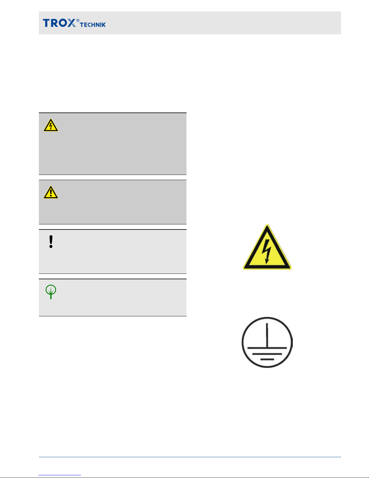
Safety notes
Symbols are used in this manual to alert readers to
areas of potential hazard. Signal words express the
degree of the hazard.
DANGER!
Imminently hazardous situation which is due to
live components and which, if not avoided, will
result in death or serious injury due to electrical
voltage.
DANGER!
Imminently hazardous situation which, if not
avoided, will result in death or serious injury
.
NOTICE!
Potentially hazardous situation which, if not
avoided, may result in property damage.
ENVIRONMENT!
Environmental pollution hazard.
Correct use
EM-LON provides a LonWorks interface for
EASYLAB base components.
Use the expansion module only for an EASYLAB
TCU3 controller or a T
AM adapter module.
Incorrect use
Do not use the expansion module for areas of application that are not described in this manual.
Do not use the expansion module:
outdoors
in wet areas
in areas with potentially explosive atmospheres
Residual risks
Failure of the network interface does not affect the
control function of the volume flow controller but
does af
fect data exchange with the central BMS.
Additional safety measures are required for safetyrelevant applications.
Safety signs
The following symbols and signs are usually found
in the work area. They apply to the very location
where they are found.
Electrical voltage
Location where a hazard due to electrical voltage
exists.
Earthing
This symbol marks all equipotential bonding connection points on EM-LON.
Safety
Expansion module EM-LON 5
Page 6
Residual risks
EM-LON is a state-of-the-art product and meets
current safety requirements. Residual risks cannot
be excluded, however
, and you should proceed with
caution.
Always observe the safety notes provided in the following chapters of this manual to reduce health
hazards and prevent any hazardous situations.
Electric current
DANGER!
Danger of death due to electric current!
Danger of death if live components are touched.
– Switch off the supply voltage and secure it
against being switched on again before
working on the unit.
–
Only skilled qualified electricians are allowed
to work on live components.
– Equipotential bonding is required.
Risk of damage to property
Temperature differences
NOTICE!
Risk of damage to property due to large temperature differences
If EM-LON has been kept in an unheated area,
condensation may form and damage the electronic components beyond repair
.
– Let EM-LON warm up to room temperature
before you install it.
Electrostatic charge
NOTICE!
Risk of damage to property due to electrostatic charge
Electrostatic charge can damage the electronics
of the expansion module.
– Before you remove the expansion module
from its protective wrapping, touch an equipotentially bonded metal surface, e.g. a
water pipe, for electrical earthing.
–
Avoid skin contact with any components or
printed circuits on the expansion module or
the main PCB.
– Wear conductive footwear and antistatic
clothing.
System owner's responsibility
System owner's obligations
EM-LON is intended for commercial use. The
system owner is therefore subject to the legal obligations of occupational health and safety regulations.
In addition to the safety notes in this manual, the
applicable regulations for safety
, accident prevention and environmental protection must also be
complied with.
Qualified staff
Qualification
The work described in this manual has to be carried
out by individuals with the qualification, training,
knowledge and experience described below:
Network administrator
Network administrators design, install, configure
and maintain the IT infrastructure in companies or
organisations.
Safety
Expansion module EM-LON6
Page 7
Skilled qualified electrician
Skilled qualified electricians are individuals who
have suf
ficient professional or technical training,
knowledge and actual experience to enable them to
work on electrical systems, understand any potential hazards related to the work under consideration,
and recognise and avoid any risks involved.
Any work has to be carried out by individuals who
can be expected to carry out their assigned duties
reliably. Individuals whose reaction time is delayed
due to alcohol, drugs or other medication must not
carry out any work.
Passwords
Webserver setup is password protected to prevent
unauthorised individuals from entering or changing
data.
Environmental protection
The following substances and materials which
are hazardous to the environment are used in
this product:
Electrical and electronic parts
Electrical and electronic parts may contain toxic
materials and substances. These parts have to be
disposed of separately from other waste, i.e. taken
to your local reuse and recycling centre or disposed
of by a specialist disposal company.
Batteries
Batteries contain toxic heavy metals. They are hazardous waste and must be taken to a hazardous
waste collection point or disposed of by a specialist
company
.
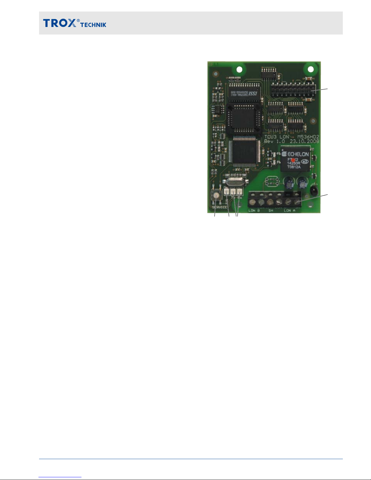
3 Structure and functional description
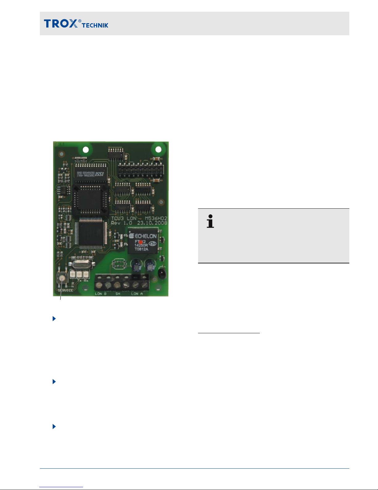
①
②
③④⑤
Fig. 1: EM-LON
①
Plug base for connection with the EASYLAB
main PCB
②
Terminals for the LonWorks network
③
Indicator lights – data transfer; TX: Sending
data; RX: Receiving data
④
Service pin push button indicator light
⑤
Service pin
Status LEDs
There are two LEDs on the expansion module:
RX LED, green, blinking - Receiving data
TX LED, green, blinking - Sending data
Service pin LED, red - ???
Structure and functional description
Expansion module EM-LON 7
Page 8

Functional description
Expansion module EM-LON provides the EASYLAB
base components (controller TCU3 or
adapter
module TAM) with a LonWorks interface to link
rooms or individual volume flow controllers to the
central BMS.
The LonWorks interface supports the EASYLAB
room operating mode scheme. It is possible to set
operating mode defaults in order to control different
volume flow rates for daytime and night-time operation; it is also possible to increase or reduce the air
change rate by a certain amount (volume flow rate
setpoint change), e.g. to influence the room temperature.
Using the LonWorks interface, an individual alarm
management system can be set up by consolidating
configurable EASYLAB alarms. The interface also
enables the transfer of actual operating values such
as volume flow rates and damper blade position for
a controller or for all controllers in a room.
The PCB contains terminals for the LonWorks network and a service pin push button with indicator
light.
The expansion module is mounted with a header to
the main PCB of the EASYLAB base component.
To simplify diagnosis during commissioning the
expansion module is equipped with two additional
indicator lights that indicate data traffic on the LonWorks interface.
Standard network variables are used for the communication within the LonWorks infrastructure.
These variables ensure unambiguous data
exchange between the nodes.
For commissioning, it is necessary to link the network variables between the nodes (binding). Project
software is used to link the outputs of a node to the
inputs of other nodes.
Structure and functional description
Expansion module EM-LON8
Page 9
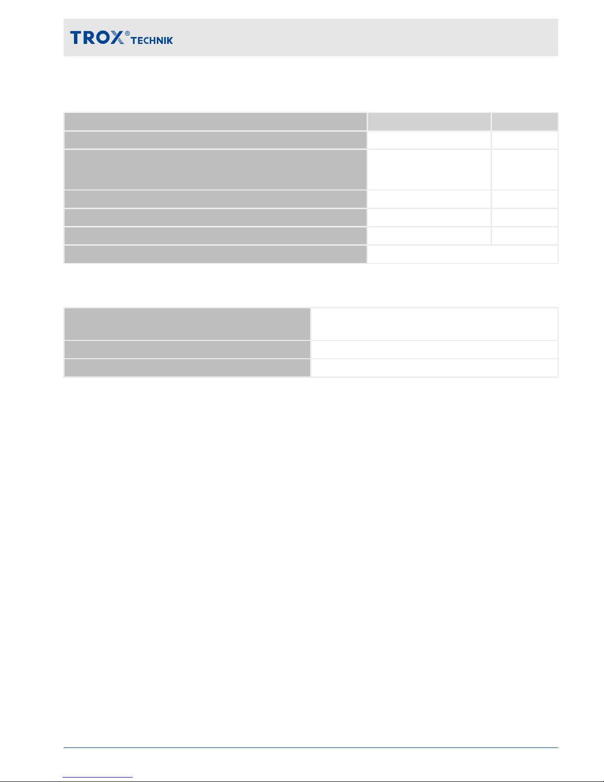
4 Technical data
Item Value Unit
Dimensions (B x H x T) 78 × 15 × 100 mm
Supply voltage
(from the controller TCU3 or adapter module T
AM)
5 V DC
Acceptable temperature range for storage -10 to +70 °C
Acceptable temperature range for operation –0 to +50 °C
Maximum humidity, no condensation (for storage and operation) < 90 %
Protection level IP 20
Communication interface
Physical interface LonWorks transceiver FTT-10A (Free Topology, Twisted
Pair)
Protocol LonWorks
Data transfer speed
Firmware version
4.0
Supported groups of devices
EASYLAB TCU3 / T
AM from software version 7.0
Network connection
6 terminals for cable cross sections of 0.12 – 1.5 mm² (LON A, LON B and shielding, two of each)
Ä
on page 11
Displays
Two status indicator lights, Rx and Tx,
Ä
‘Status LEDs ’ on page 7
Technical data
Expansion module EM-LON 9
Page 10

5 Delivery and storage
Delivery check
Check delivered items immediately after arrival for
transport damage and completeness.
Properly dispose of packaging material.
A complete shipment includes:
EM-LON expansion module
Pin header
Mounting material
–
Distance pieces (4x)
– Fixing screws with washers (4x)
Ground strap
Installation manual
Carrying the expansion module
If possible, take the module in its transport
packaging up to the installation location.
Do not remove the protective wrapping until
just before installation.
Storage
If you need to store EM-LON, make sure that the
following conditions apply:
Store in its original (antistatic) packaging.
Do not store outdoors.
Store in a dry and dust free place.
Store away from direct sunlight.
Do not expose to any aggressive media.
Avoid any mechanical impact.
Storage temperature: -10 °C to +70 °C.
Relative humidity: < 90 %, no condensation.
If a product has to be stored for more than
3 months, regularly check the general condition of all parts and of the packaging.
Delivery and storage
Expansion module EM-LON10
Page 11
6 Installation
Personnel:
Skilled qualified electrician
Materials:
EM-LON expansion module
Pin header
Distance pieces (4x)
Fixing screws with washers (4x)
DANGER!
Danger of death due to electric current!
Danger of electric shock! Do not touch any live
components!
– Switch off the supply voltage and secure it
against being switched on accidentally
before working on any electrical equipment.
–
Only skilled qualified electricians are allowed
to work on live components.
Expansion module EM-LON is to be fitted into the
casing of a TCU3 controller or T
AM adapter
module.
1.
Electrostatic charge can damage the electronics. For this reason, first touch an equipotentially bonded metal surface, e.g. a
water pipe, for electrical earthing before you
remove the unit from its protective wrapping.
A
void skin contact with any components or
printed circuits on the expansion module or
the main PCB.
2.
Switch of
f the supply voltage to the TCU3
controller or TAM adapter module and
secure it against being switched on accidentally. Then open the cover of the TCU3 or
TAM casing (see instructions for the respective device).
①
②
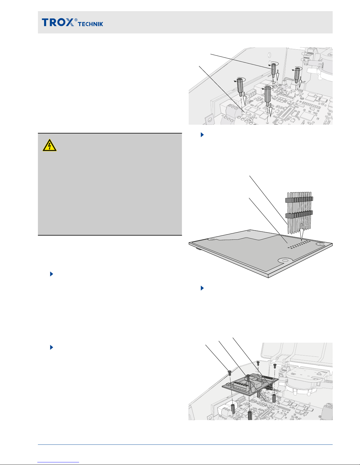
3.
Screw the four distance pieces ① into the
corresponding openings in the TCU3 or TAM
main PCB ② and tighten them (hand-tight
only).
③
④
4.
T
ake the pin header ③ and push it with the
longer ends from below through the expansion module ④; push the pin header just far
enough such that the pins protrude slightly
on the upper side.
③
⑤
⑥
Installation
Expansion module EM-LON 11
Page 12
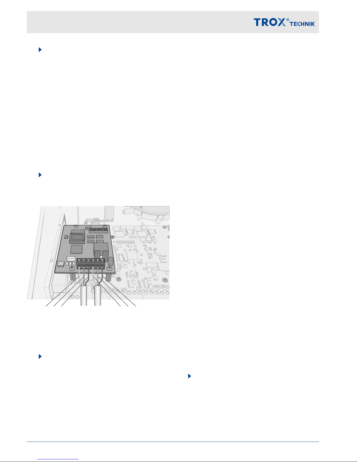
5.
T
ake the expansion module PCB with the
upside up and position it on the TCU3 or
TAM main PCB such that the pin header ③
is exactly above the corresponding plug-in
base ⑤, and the holes for the distance
pieces are above the distance pieces. Then
press the PCB onto the distance pieces.
In case the positions do not exactly line up,
check whether the pin header is still correctly positioned. Repeat step 2.
If you have pushed the pins too far through
the PCB (step 2), the electrical connection
may not work properly. Repeat step 2.
6.
Fix the PCB using the four fixing screws ⑥.
T
ighten the screws only hand-tight.
Connecting data cables
① ①② ③ ④ ② ③ ④
①
Data cable
②
LON-B
③
LON-A
④
SH (shield)
7.
EM-LON has terminals for two data cables
of a LonW
orks network. Depending on the
network topology, controllers at the end of a
chain may be connected to one bus, controllers at other positions in the chain may be
connected to two buses.
Strip the insulation from the bus cable (at
least two wires), insert the bare wires into
the terminals and tighten the screws by
hand.
Make sure that the polarity of the conductor
pairs is correct. Incorrect polarity will result
in inverted data signals and hence communication errors.
Fix the data cables to the casing using the
wire clamping bracket.
Connect the shield of shielded cables to the
SH terminals. Within a bus segment connect
the shield only at one point to the earth.
Earthing the shield at every controller will
lead to voltage disturbances.
A maximum of 32 units can be operated on
one network segment. T
o avoid cable reflections, network segments must be terminated
at both ends with 120Ω bus terminal resistors. PCBs of revision 2 and higher allow
you to fit terminal resistors directly onto the
PCB. (see page 17)
Connect the shield of shielded cables to the
SH terminals. Within a chain (channel) connect the shield only at one point to the earth.
Earthing the shield at every controller will
lead to voltage disturbances.
Recommended data cable
Bus cables to TIA 568A, category 5
Belden 8471 or 85102
Cables to DOCSIS specification level IV
JY(St)Y 2×2×0.8 (use only twisted pair
for LON-A and LON-B)
8.
Close the cover of the TCU3 or T
AM casing
(see instructions for the respective device).
Then switch on the power supply to TCU3 or
TAM again.
Installation
Expansion module EM-LON12
Page 13
7 Commissioning / Configuration
Personnel:
Network administrator
Commissioning the LonWorks interface requires
detailed technical knowledge and special software,
e.g. Echelon LonMaker
. Only specialist personnel
should do the commissioning.
Commissioning
①
1.
Press the service pin push button (1) and
download the software for the
EASYLAB LonW
orks node. The software for
EM-LON is available for download on our
website.
Binding
2.
Create the logical bindings for the network
variables to be transferred by EM-LON. As
an alternative, use polling.
Configuration
3.
If necessary
, adjust the configuration
nciMaxSendTime or nciConfig_Occ,
Required TCU3 software version
EM-LON with firmware 4.0 requires that TCU3 software 7.0 or higher is installed on the TCU3 controller or T
AM adapter module.
The TCU3 software version is displayed in the
EasyConnect software, ‘Diagnosis’ , ‘Basic Device’
line.
A product sticker on the main PCB also carries the
software version number (only for version 3 or
higher).
With earlier software versions there is no data
exchange between the expansion module and
TCU3. This means that the network is not able to
read out current values from the EASYLAB device
or to send any values to the EASYLAB system.
You need not adapt the controller configuration
with the EasyConnect configuration software for
the expansion module to work.
8 Interface information
For a description of all LonW
orks interface data
points refer to the configuration manual for EMLON.
You can download the document from
www.troxtechnik.com.
Commissioning / Configuration
Expansion module EM-LON 13
Page 14
9 Removal and disposal
Safety notes regarding removal and disposal
Electric current
DANGER!
Danger of death due to electric current!
Danger of death if live components are touched.
– Switch off the supply voltage and secure it
against being switched on again before
working on the unit.
–
Only skilled qualified electricians are allowed
to work on live components.
– Equipotential bonding is required.
Removal
1.
Make sure that the voltage supply has been
interrupted.
2.
Unplug the network cable.
3.
Remove ground strap.
4.
Remove the expansion module.
Disposal
ENVIRONMENT!
Risk of harm to the environment due to incorrect disposal of materials.
Incorrect disposal can harm the environment.
– Have electronic waste and electronic com-
ponents disposed of by an approved specialist disposal company
.
– If you are not sure how to dispose of any-
thing in an environmentally friendly manner,
contact your local authorities or a specialist
disposal company.
If no return or disposal agreement is in place, any
disassembled components should be disposed of
by an approved specialist disposal company
.
Removal and disposal
Expansion module EM-LON14
Page 15

Expansion module EM-LON 15
Page 16

Expansion module EM-LON16
 Loading...