

Page 1
Product overview
①
②
③
④
⑥
⑤
⑧
⑨
⑩
⑦
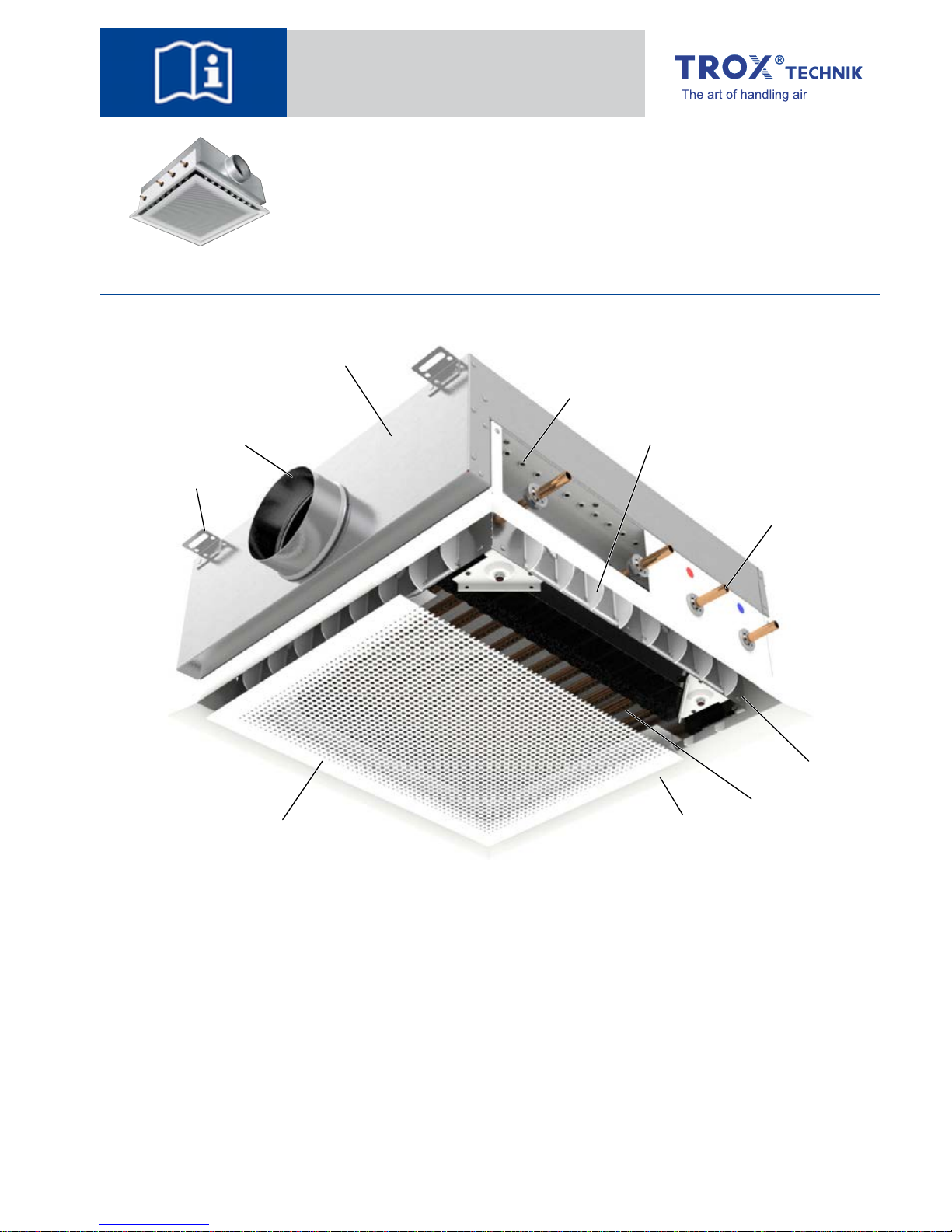
Fig. 1: Schematic illustration of DID614
①
Hanging bracket
②
Primary air spigot
③
Casing
④
Nozzle plate with punched nozzles
⑤
Air control blades (optional)
⑥
Water connections
⑦
Encasement (optional)
⑧
Heat exchanger
⑨
Front frame
⑩
Induced air grille
Installation manual
en/GB
Active chilled
beams
Type DID614
TROX GmbH
Heinrich-Trox-Platz
47504 Neukirchen-Vluyn
Germany
Phone: +49 (0) 2845 2020
Fax: +49 (0) 2845 202265
E-mail: [email protected]
http://www.troxtechnik.com
A00000048714, 04/2015, © 2015 TROX GmbH
Active chilled beams Type DID614
1
Page 2
Important notes
Information on the installation manual
This manual enables operating or service personnel
to correctly install the product described below and
to use it safely and efficiently.
It is essential that these individuals read and fully
understand this manual before starting any work.
The basic prerequisite for safe working is to comply
with the safety notes and all instructions in this
manual.
The local regulations for health and safety at work
and general safety regulations also apply.
Qualified staff
Specialist personnel
Specialist personnel are individuals who have sufficient professional or technical training, knowledge
and actual experience to enable them to carry out
their assigned duties, understand any potential hazards related to the work under consideration, and
recognise and avoid any risks involved.
Specialized personnel
Specialised personnel are personnel, who due to
their specialized training, skills, and experience, as
well as knowledge of the applicable standards and
regulations, are capable of executing the tasks
assigned to them, and of recognizing possible hazards and avoiding them on their own.
Limitation of liability
The information in this manual has been compiled
with reference to the applicable standards and
guidelines, the state of the art, and our expertise
and experience of many years.
The manufacturer does not accept any liability for
damages resulting from:
Non-compliance with this manual
Incorrect use
Operation or handling by untrained individuals
Unauthorised modifications
The actual scope of delivery may differ from the
information in this manual for special constructions,
additional order options or as a result of recent
technical changes.
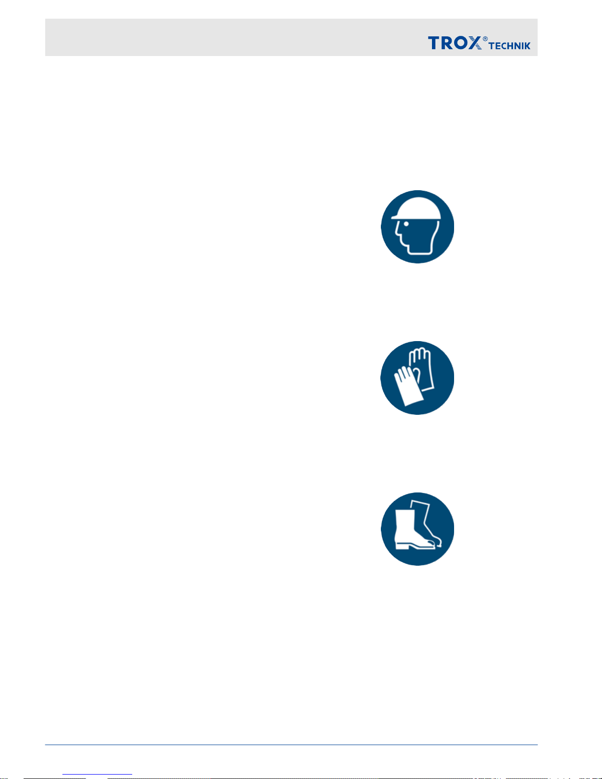
Personal protective equipment
Personal protective equipment must be worn for all
work in order to reduce health or safety hazards to
the minimum.
The appropriate protective equipment for a job must
be worn for as long as the job takes.
Industrial safety helmet
Industrial safety helmets protect the head from
falling objects, suspended loads, and the effects of
striking the head against stationary objects.
Protective gloves
Protective gloves protect hands from friction, abrasions, punctures, deep cuts, and direct contact with
hot surfaces.
Safety shoes
Safety shoes protect the feet against crushing,
falling parts, and slipping on slippery ground.
Correct use
Active chilled beams provide centrally conditioned
primary air (fresh air) to the room. Heat exchangers
are used for additional cooling and/or heating.
Important notes
Active chilled beams Type DID6142
Page 3

Incorrect use
WARNING!
Danger due to incorrect use!
Incorrect use of the unit can lead to dangerous
situations.
Never use the unit:
– in areas with potentially explosive atmos-
pheres
–
in humid rooms
– in rooms with aggressive or dust-laden air
Important notes
Active chilled beams Type DID614 3
Page 4

Technical data
Designation Value
Primary air volume flow rate 9 – 97 l/s, 32 – 350 m³/h
Cooling capacity Up to approx. 2150 W
Heating capacity Up to approx. 2000 W
Max. operating pressure, water side 6 bar
Max. operating temperature 75 °C
(55 °C when using flexible connecting hoses)
Minimum operating temperature 6 °C
Dimensions
L1
L2
634
595
H
L
Z
82
8
Z
175X 105 105
A
∅D
385
B
X
࿆
࿇
Fig. 2: Dimensional drawing of DID614
Ⓐ
4-pipe
Ⓑ
2-pipe
Technical data
Active chilled beams Type DID6144
Page 5

Variants for ceiling installation
Dimensions [mm]
L
B L
1
L
2
X
593
×
593 522 444 104
598
×
598 522 444 106.5
618
×
618 522 444 116.5
623
×
623 522 444 119
1193
×
593 1122 1044 104
1198
×
598 1122 1044 106.5
1243
×
618 1147 1069 116.5
1248
×
623 1147 1069 119
L = total length (grille), B = total width (grille)
Variants for freely suspended installation
Dimensions [mm]
L
B L
1
L
2
X
900
×
900 522 444 257.5
1525
×
900 1147 1069 257.5
L = total length (grille), B = total width (grille)
Dimensions [mm]
∅D A H
123 125 230
158 143 245
Weight [kg]
Nominal size [mm] DID614 Contained water
600 × 600 16 2
1200 × 600 30 3
1250 × 625 31 3
900 × 900 21 2
1525 × 900 38 3
Technical data
Active chilled beams Type DID614 5
Page 6
Transport and storage
Transport
CAUTION!
Danger of injury from sharp edges, sharp corners and thin sheet metal parts!
Sharp edges, sharp corners and thin sheet metal
parts may cause cuts or grazes.
– Be careful when carrying out any work.
– Wear protective gloves, safety shoes and a
hard hat.
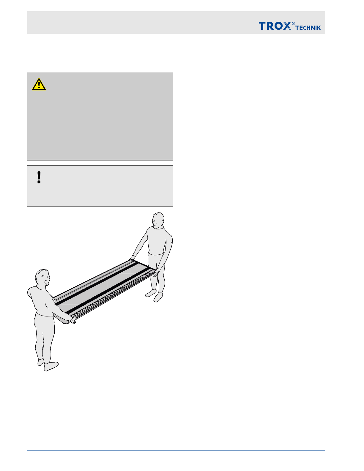
NOTICE!
Carry the unit in pairs in order to prevent any
damage.
Fig. 3: Carrying the unit in pairs
Use only lifting and transport gear designed for the
required load. Always secure the load against tipping and falling.
Upon delivery, carefully remove the packaging and
check the unit for transport damage and completeness.
Storage
Please note:
Store the unit only in its original packaging
Protect the unit from the effects of weather
Protect the unit from humidity, dust and con-
tamination
Storage temperature: –10 to 50 °C
Relative humidity: 95 % max., non-condensing
Transport and storage
Active chilled beams Type DID6146
Page 7
Ceiling installation
Ceiling systems
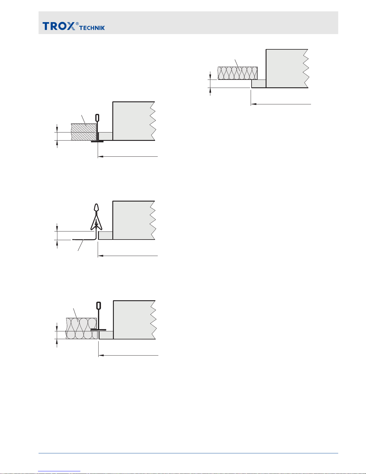
Active chilled beams are typically installed in suspended ceilings. Installation in the most common
ceiling systems is shown below.
593 / 618
8
①
②
Fig. 4: Ceiling installation, visible T-bars
①
DID614
②
Ceiling tile
598 / 623
8
①
②
Fig. 5: Ceiling installation with clamping profile
①
DID614
②
Ceiling tile
8
598 / 623
①
②
Fig. 6: Ceiling installation, concealed T-bars
①
DID614
②
Ceiling tile
598 / 623
8
②
①
Fig. 7: Ceiling installation, plasterboard ceiling
①
DID614
②
Plasterboard ceiling
Ceiling installation
Active chilled beams Type DID614 7
Page 8

Installing the unit
Personnel:
Specialized personnel
Protective equipment:
Industrial safety helmet
Safety shoes
Protective gloves
If possible, install the unit before fixing the ceiling
tiles; if this is not possible, remove the adjacent
ceiling tiles.
Only work in pairs; preferably use a lift.
DANGER!
Danger of death from the fall of suspended
loads!
– Only use fixing materials designed for the
required load.
– Use all hanging brackets supplied.
–
Stand clear of suspended loads, unless
properly secured.
– Check secure fixing after installation.
x4
L2
595
1
L2
595
x4
2
3
4a
4b
Ceiling installation
Active chilled beams Type DID6148
Page 9

Connecting the water pipes
CAUTION!
Hot surface!
Danger of burn or scald injuries when working on
the hot water system.
Before working on the water-side connections,
shut down the system, depressurise it and let it
cool down.
The heat exchanger is fitted with water flow and
water return connections:
Fig. 8: DID614 with 4-pipe system
2-pipe system: 2 water connections
4-pipe system: 4 water connections
Make sure that the water temperature does not fall
below the dew point.
Water connection Spanner Type of connection
Copper tubes
12 × 1 mm
– Soldered (rigid)
Flexible hoses
(accessory)
G 1/2" external
thread and flat seal
SW22 Screw connection
(rigid)
Flexible hoses
(accessory)
G 1/2" union nut and
flat seal
SW24 Screw connection
(rigid)
Flexible hoses
(accessory)
Connecting the unit – screw connection
Personnel:
Specialist personnel
Protective equipment:
Industrial safety helmet
Safety shoes
Protective gloves
Ensure that the surfaces are clean
1. Insert seal and tighten screw connection by
hand.
NOTICE!
Incorrect assembly will damage the heat
exchanger!
Always use a suitable tool to counter the tightening force in order to prevent any damage.
2. Tighten screw connections with a spanner.
NOTICE!
Subzero temperatures will damage the heat
exchanger!
Only fill the heat exchanger if there is no danger
of freezing.
3. Fill the heat exchanger and vent it. To fill the
system, use clean tap water (pH value 6.5 to
9) or a water glycol mixture (max. 30%
glycol).
Connecting the water pipes
Active chilled beams Type DID614 9
Page 10

4. Check the system for leaks immediately
after installation and then in regular intervals.
Connecting the ductwork
Active chilled beams are fitted with a primary air
(fresh air) connection.
Spigots are suitable for circular ducts to EN 1506 or
EN 13180.
Commissioning
Before you start commissioning:
Check active chilled beams for correct position
Remove protective films, if any
Ensure that all connections are correct
Ensure that all active chilled beams are clean
and free from residues and foreign matter
Ensure that the water system including the
heat exchanger has been filled and vented
Setting the air control blades
The air discharge pattern can be changed by
adjusting the optional air control blades in 15° increments up to 45° to the left or right.
Three different air patterns can be set.
NOTICE!
Incorrect handling will damage the air control
blades!
To avoid any damage, always use both hands to
move the air control blades.
o
45°
45°
Fig. 9: Changing the air discharge pattern
① ② ③
Fig. 10: Examples
①
Straight air discharge
②
Angled air discharge
③
Divergent air discharge
Connecting the ductwork
Active chilled beams Type DID61410
Page 11
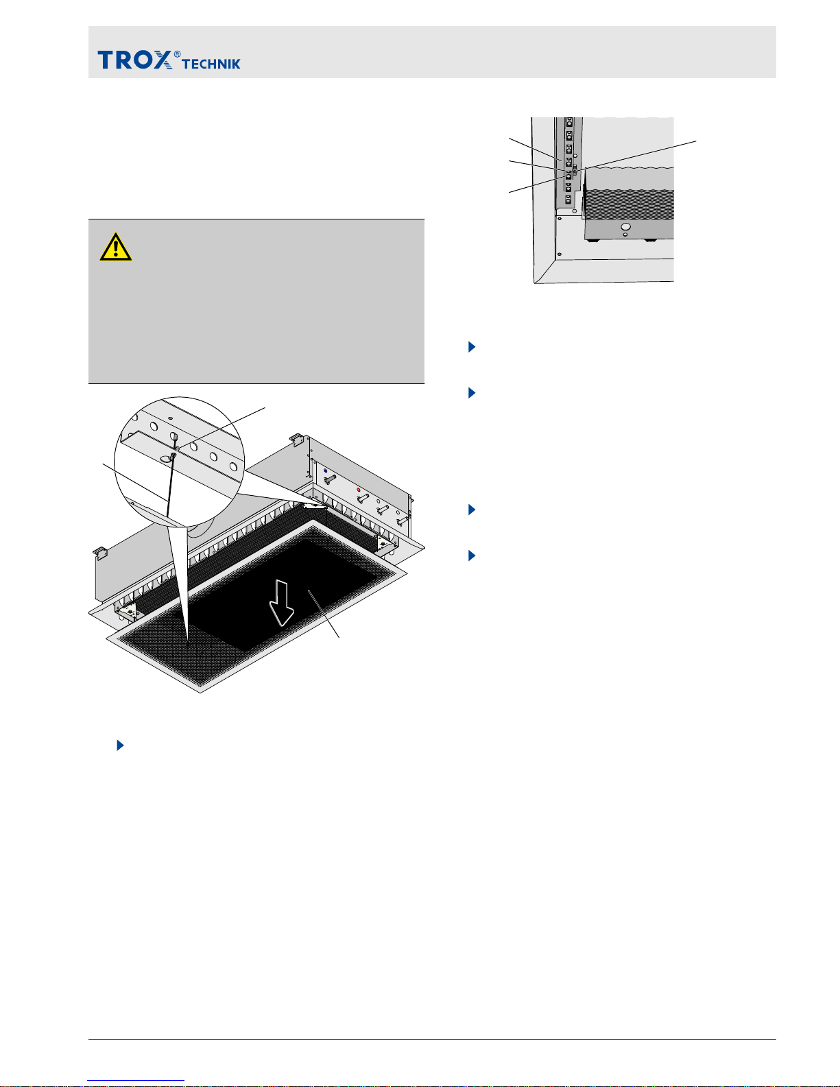
Adjusting the nozzles
The DID614 is fitted with adjustable twin nozzles
that allow for adapting the airflow velocity to
changed operating conditions at a later stage, if
required.
CAUTION!
Hot surface!
Danger of burn injuries when working on the hot
water system.
Before working on the water-side connections,
shut down the system and let it cool down.
③
①
②
Fig. 11: Opening the induced air grille
1. To open the induced air grille (Fig. 11/1),
pull it down. To completely remove the grille,
unhook the safety cables (Fig. 11/2) by
pulling them down together with the
retaining plates (
Fig. 11/3).
②
③
④
①
Fig. 12: Adjusting the nozzles on the DID614
2. Loosen the Allen screws (SW4) (Fig. 12/4)
of the flat adjustment bar (Fig. 12/1).
3. Slide the flat adjustment bar back or forth to
open or close the nozzles as required:
small nozzle open (Fig. 12/2) (DS)
large nozzle open (Fig. 12/3) (DB)
both nozzles open (DA, factory setting)
4. Manually tighten the Allen screws of the flat
adjustment bar.
5. Fix the induced air grille.
Commissioning
Active chilled beams Type DID614 11
Page 12

Cleaning
Cleaning the casing
The casing may be cleaned with a damp cloth.
Sticky dirt or contamination may be removed with a
commercial, non-aggressive cleaning agent.
Cleaning agents that contain chlorine must not be
used.
Cleaning the heat exchanger
Personnel:
Specialist personnel
Protective equipment:
Industrial safety helmet
Safety shoes
Protective gloves
1. Remove the induced air grille,
Ä
on page 11
Fig. 13: Cleaning the heat exchanger
2. Carefully clean the heat exchanger with an
industrial vacuum cleaner. Be careful to not
damage the fins. We recommend using a
soft brush on the suction inlet.
3. After cleaning, re-attach the safety cables,
and screw-fix and close the grille.
CAUTION!
Danger of head injuries from the fall of
the induced air grille!
Check that the induced air grille and
safety cables are securely fixed!
Cleaning
Active chilled beams Type DID61412
 Loading...