

Page 1
Operation Manual
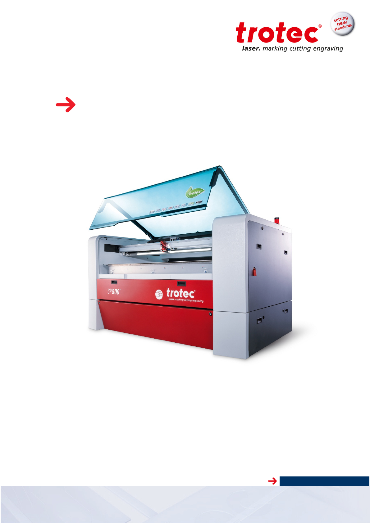
SP 500
www.troteclaser.com
Page 2

SP 500
TROTEC PRODUKTIONS UND VERTRIEBS GMBH
Linzer Straße 156
A – 4600 Wels
AUSTRIA
Tel.: ++43/7242/239-7000
Fax: ++43/7242/239-7380
E-Mail: techsupport@troteclaser.com
www.troteclaser.com
Released December 2015
Copyright
This documentation with all illustrations is intellectual property of Trotec Produktions- u. Vertriebs
GmbH.
The entire documentation is given to the user for personal use only. This documentation must not be
reproduced or made available to others without our written permission. Any breach of law will be prosecuted.
Trotec Produktions- u. Vertriebs GmbH cannot be held responsible for any direct or
indirect damages, which result from using or working with the products electric circuits or software described herein. The apparatus must be used only by trained and
skilled personnel. Before use the manual should be read and followed carefully.
Furthermore Trotec Produktions- u. Vertriebs GmbH reserves the right to change or
alter any product described herein without prior notice.
In case of failure, please check the device first. If unsuccessful, please note all data of
the device (year of manufacture, software version, etc.) and call us from a telephone
next to the switched on device.
For queries or technical problems please contact your dealer or Trotec Produktions- u.
Vertriebs GmbH directly at the above address.
Version 2.0 © TROTEC Produktions- u. Vertriebs GmbH
Technical changes reserved Freilingerstraße 99, A-4614 Marchtrenk
www.troteclaser.com
2 / 51
Page 3

SP 500
Contents
1 Manufacturing label ......................................................................................................................... 5
2 Product Components ....................................................................................................................... 6
3 Preface ............................................................................................................................................... 7
How to use the operation manual ............................................................................................... 7
Product Tracking ......................................................................................................................... 8
4 Technical Data .................................................................................................................................. 9
General Description .................................................................................................................... 9
Intended Use .............................................................................................................................. 9
Dimensions ............................................................................................................................... 10
Technical Specification ............................................................................................................. 11
Electrical Connection ................................................................................................................ 13
4.5.1 Electrical connection for laser system ............................................................................ 13
4.5.2 Electrical connection for water cooling unit (optional) .................................................... 13
Materials ................................................................................................................................... 14
1 For your Safety ................................................................................................................................. 15
5 For your Safety ............................................................................................................................... 15
Safety Indication ....................................................................................................................... 15
5.1.1 Intended user group ....................................................................................................... 15
5.1.2 Operating instructions / Safety equipment ..................................................................... 15
General Safety Instructions ...................................................................................................... 16
5.2.1 General .......................................................................................................................... 16
5.2.2 Laser Safety ................................................................................................................... 19
5.2.3 Transport Safety ............................................................................................................. 21
Secondary Risks ....................................................................................................................... 22
5.3.1 General ........................................................................................................................... 22
5.3.2 Crushing hazard ............................................................................................................. 22
Signage ..................................................................................................................................... 23
2 Transport - Storage – Setup ............................................................................................................ 24
6 Transport – Storage - Setup .......................................................................................................... 25
Forklift transport ........................................................................................................................ 25
Lifting points .............................................................................................................................. 25
Shipping conditions ................................................................................................................... 26
Unloading, inspection and damage reporting ........................................................................... 26
Storage conditions .................................................................................................................... 26
Storage Location ....................................................................................................................... 26
Installation Site ......................................................................................................................... 27
Space Requirements ................................................................................................................ 27
Necessary Feed Lines .............................................................................................................. 27
Setup......................................................................................................................................... 28
7 Connections .................................................................................................................................... 29
8 Machine view .................................................................................................................................. 30
9 Operation ......................................................................................................................................... 31
www.troteclaser.com
Version 2.0 © TROTEC Produktions- u. Vertriebs GmbH
Technical changes reserved Freilingerstraße 99, A-4614 Marchtrenk
3 / 51
Page 4

SP 500
Key pad – Overview .................................................................................................................. 31
Key pad – Description ............................................................................................................... 32
Workpiece Removal Door ......................................................................................................... 36
Pass-through opening (optional) .............................................................................................. 36
Exhaust System ........................................................................................................................ 37
Tables ....................................................................................................................................... 38
9.6.1 Base Frame (with/without lamellas) ............................................................................... 38
9.6.2 Engraving Table (Standard table) .................................................................................. 38
9.6.3 Vacuum Table ................................................................................................................ 39
9.6.4 Cutting Table .................................................................................................................. 39
Lenses ...................................................................................................................................... 40
Start of Operation ..................................................................................................................... 41
3 Maintenance ...................................................................................................................................... 43
Cleaning optics on the Laser Head .......................................................................................... 43
Cleaning the Mirrors ................................................................................................................. 44
Maintenance plan ..................................................................................................................... 45
10 Appendix ......................................................................................................................................... 46
EC – Declaration of Conformity ................................................................................................ 46
Acceptance report ..................................................................................................................... 47
Training Verification Form......................................................................................................... 48
Response Form ........................................................................................................................ 49
How to create a Service File ..................................................................................................... 50
Version 2.0 © TROTEC Produktions- u. Vertriebs GmbH
Technical changes reserved Freilingerstraße 99, A-4614 Marchtrenk
www.troteclaser.com
4 / 51
Page 5

SP 500
1 Manufacturing label
You find the manufacturing label with the CE-sign on the rear side of the machine.
Enter the serial number, model and year of manufacture from the manufacturing label here.
This information is important for troubleshooting problems with the product and for ordering replacement parts.
Version 2.0 © TROTEC Produktions- u. Vertriebs GmbH
Technical changes reserved Freilingerstraße 99, A-4614 Marchtrenk
www.troteclaser.com
5 / 51
Page 6
SP 500
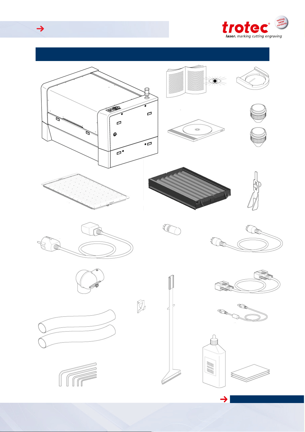
2 Product Components
2,0“
Lenses
Machine
Engraving table
(standard table)
Power cord
Operating instructions
DVD
Table base frame
Bypass jumper for
Please read!
ø 5mm
Nozzles
ø 2mm
(per order)
Focusing tool
Exhaust valve
2 exhaust hoses
Allen wrench kit
Pass-through
Broom with
holder
Exhaust connection cable
RS232 cable (per order)
USB cable
Cleaning kit
www.troteclaser.com
Version 2.0 © TROTEC Produktions- u. Vertriebs GmbH
Technical changes reserved Freilingerstraße 99, A-4614 Marchtrenk
7-part
6 / 51
Page 7

SP 500
3 Preface
How to use the operation manual
This operation manual is intended to simplify the following for you:
Learning about the machine, and
Utilizing the machine’s capabilities according to its intended use.
The operating manual contains important notes on how to operate the machine:
Safely,
Properly, and
Economically
Following the operating instructions helps you to:
Avoid hazards and risks,
Minimize repair costs and downtimes, and
Increase the reliability and service life of your machine.
Version 2.0 © TROTEC Produktions- u. Vertriebs GmbH
Technical changes reserved Freilingerstraße 99, A-4614 Marchtrenk
www.troteclaser.com
7 / 51
Page 8

SP 500
Product Tracking
We have a legal duty to track our products after delivery to our customers.
In particular, this relates to:
Recurring faults in functions
Anything that is unclear, e.g. in operation, maintenance or instructions
Any accidents that occur
Other unusual observations
Recommendations for improvement, requests
This information serves as a basis for potential corrections and/or changes to the product, and it is
therefore of great interest to us.
We request that you inform us of any such events and offer us your recommendations. This is the only
way that we can improve our products as necessary, and to make them as safe and reliable as possible.
Please use the response forms included in the Appendices for this purpose.
Version 2.0 © TROTEC Produktions- u. Vertriebs GmbH
Technical changes reserved Freilingerstraße 99, A-4614 Marchtrenk
www.troteclaser.com
8 / 51
Page 9

SP 500
4 Technical Data
General Description
The SP 500 consists of a machine and a base frame.
All electronic components are integrated in the base frame.
All necessary connections are made on the back side of the SP 500.
Controls for the SP 500 are located on the keypad.
The SP 500 is equipped with an interlock safety system. When the interlock is activated, only setup
tasks can be performed on the SP 500.
The machine has a manual table changing system that enables use of the optimal table for specific
jobs. This system ensures faster and safer table changes.
Intended Use
The Trotec SP 500 is designed for engraving and cutting of the materials listed in this document.
Version 2.0 © TROTEC Produktions- u. Vertriebs GmbH
Technical changes reserved Freilingerstraße 99, A-4614 Marchtrenk
www.troteclaser.com
9 / 51
Page 10
SP 500
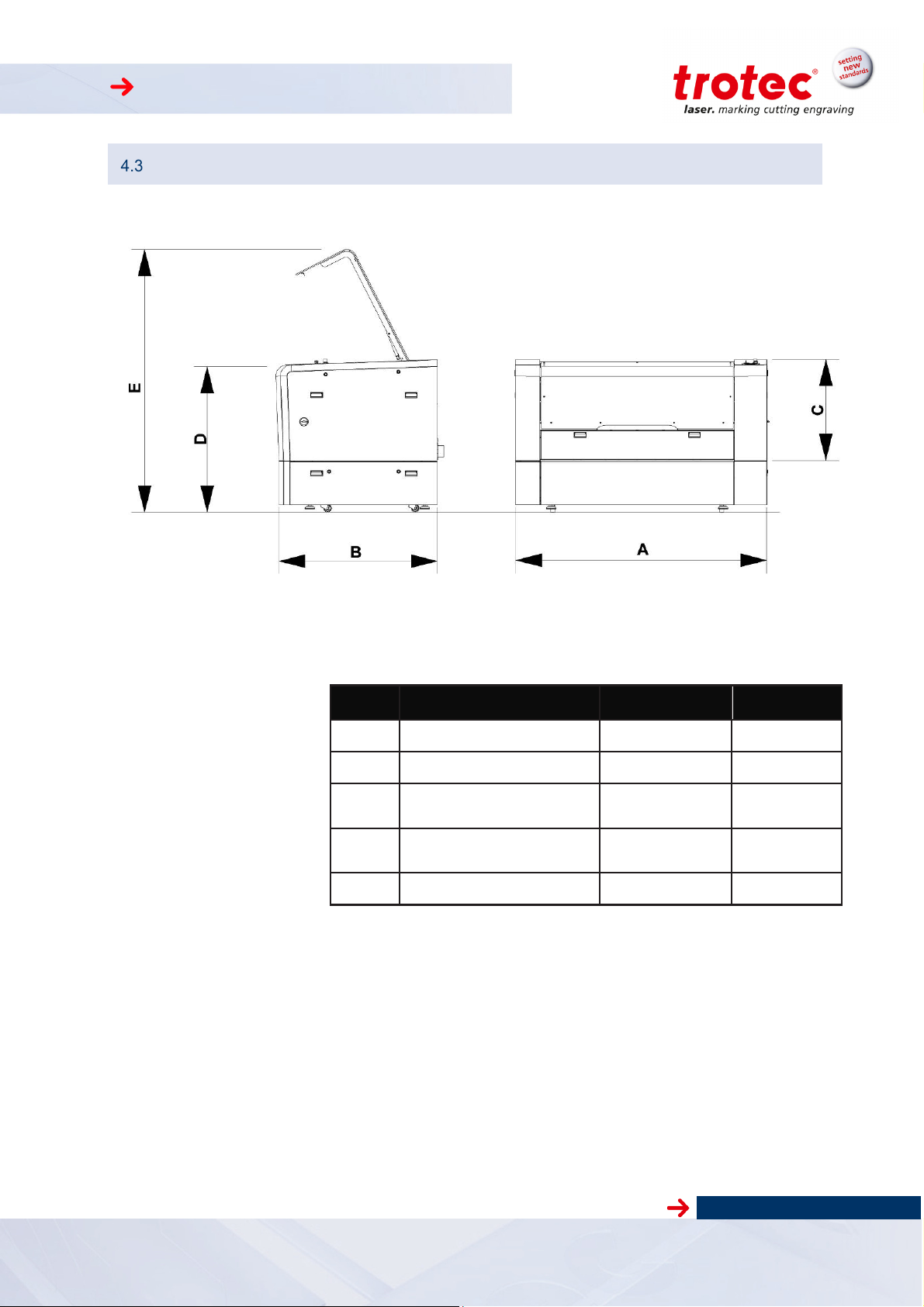
Dimensions
Item Description Dimension Units
A
B
C
D
E
Length 1920 (79.59)
mm (inch)
Width 1240 (48.82) mm (inch)
Height, closed without
base frame
Height, closed with
base frame
Height, open
Weight – depends on product model ............... 550 to 600 kg
780 (30.71) mm (inch)
1140 (44.88) mm (inch)
2100 (82.68) mm (inch)
(1210 to 1320 lbs)
Version 2.0 © TROTEC Produktions- u. Vertriebs GmbH
Technical changes reserved Freilingerstraße 99, A-4614 Marchtrenk
www.troteclaser.com
10 / 51
Page 11

SP 500
• Mechanics
• Options
Technical Specification
Working area 1245 x 710 mm (49 x 28 in) or optional 1245 mm (40 in) x ∞ (with pass-through)
Loading area 1420 x 820 mm (56 x 32 in) or optional 1420 mm (56 in) x ∞ (with pass-through)
Max. height of work piece 112 mm (4.4 in) slat cutting table, 95 mm (3.7) aluminum cutting grid table and
acrylic cutting grid table, 98 mm (3.7) vacuum table; at removed table 300mm(12
in) at an area 1245 x 610mm (49 x 24 in) (flatness at removed tables cannot be
guaranteed)
Work piece table Multifunctional table concept: slat, aluminum, acrylic cutting grid table or vacuum
table – one table included as standard; also available: honeycomb cutting tabletop, aluminum cutting grid tabletop or acrylic cutting grid Tabletop; electronic,
programmable z-axis with servo motor
Speed of motion system 254 cm/sec. (100 in/sec)
Acceleration 19m/s² (748 in/sec²)
Motor Brushless DC servomotor
Encoder Increment measuring system
Optical elements lens and all mirrors air-flushed and therefore protected from soiling (preinstalled
air pump)
Lens 2.0" (standard); 2.5“, 5.0" (optional), 2.5“ clearance lense (optional) – gives 12,5
mm (0,5 in) more clearance than standard lenses, 3.75” rotary lens –additional
clearance especially for rotary jobs
Accuracy of motion system +/- 0,1 mm (0.004 in)
(on the whole working area)
Addressable accuracy 0,0046 mm (0.0002 in)
Repeatability <± 0,015 mm (0.0006 in)
Accuracy to size of parts According to material an process
Maximum material load 25 kgs (55 lbs) area load over the whole working area
Exhaust Travelling exhaust; table exhaust (with cutting- and vacuum table)
Pass-through (back) height/width: 70 x 1420 mm (2.7 x 56.0 in)
maximum material height 63mm (2.5 in)
Rotary attachment Cones and roller version; max length of work piece: 104 cm (41 in) (roller) / 84
cm (33 in) (cones); diameter: 15 cm (0,59 in) (roller) / 25 cm (10 in) (cones)
JobControl® Vision Registration mark and compensation system;
max. working area: 1245 x 710 mm (49 x 28 in)
Gas-Kit (for compressed air respectively process gas)
For control of compressed air and process gas (free of mechanical dust, water
and oil) max. flow rate 150 l/min (40 gpm) with max. 10 bar (145 psi) max. limit 4
bar on working head push fitting connection with out diameter) connection on the
machine with hose out diameter of 6mm (0.23 in)
www.troteclaser.com
Version 2.0 © TROTEC Produktions- u. Vertriebs GmbH
Technical changes reserved Freilingerstraße 99, A-4614 Marchtrenk
11 / 51
Page 12

SP 500
• Control System
• Laser
features and power
• Dimensions
• Laser Safety
• Exhaust (Minimum requirements)
• Electrical Equipment
TroCAM Basic / Advanced CAD / CAM software for perfect cutting results; inclusively nesting-function, lead-
in/lead-out, tool paths
Extraction System lead /followup time
Software JobControl Expert
Laser power Adjustable 0 – 100%
Interface hardware USB, RS-232 (RS-232 mandatory for TroCAM and CCD-camera)
Interface software ASCII, HPGL, AD-Logic System
levels
Laser features and power levels
Wavelength 10,6µm
Width x depth x height 1920 x 1240 x x1140 (780 without base frame) mm or
Weight 520 - 580 kgs / 1100 - 1300 lbs (depending on laser power)
Ambient conditions Mandatory ambient temperature +15° to +25° C or 59° to 77° F
Lead- and follow-up time fully adjustable
Sealed-off CO2 laser
With 40 – 200 watts, air – or water cooled (depending on model)
75.5 x 48.8 x 45.0 (30.7 without base frame) inches
Humidity 40% to max.. 70%, not condensing
Dust free environment (2nd degree according to IEC 60947-1)
Laser class CDRH laser safety; CE tested
Laser class 2 (Laser class 4 with pass-through)
Interlock Duplicate interlock safety system
Loading lid Front side loading lid
Volume Min. 640 m³/h at 8500 pa
Power consumption Up to 5,6 kW
Up to incl. 120 W Laser power 1x230V (L+N+PE) 50/60Hz
200 W Laser power 3x230V (3xL+N+PE) 50/60Hz
Version 2.0 © TROTEC Produktions- u. Vertriebs GmbH
Technical changes reserved Freilingerstraße 99, A-4614 Marchtrenk
www.troteclaser.com
12 / 51
Page 13

SP 500
Electrical Connection
4.5.1 Electrical connection for laser system
Laser
Power
60Wac 60Wwc 75Wac 85Wac 95Wac
Voltage 208/230V 208/230V 208/230V 208/230V 208/230V
Fuse 16A slow 16A slow 16A slow 16A slow 16A slow
Frequency 50/60Hz 50/60Hz 50/60Hz 50/60Hz 50/60Hz
Phases
Power consumption
Laser
Power
1
L,N,
Ground
(PE)
2100W 1600W 2100W 2800W 2800W
105Wac 120Wac 120Wwc 200Wwc 200Wwc US
1
L ,N ,
Ground
(PE)
1
L , N,
Ground
(PE)
1
L , N,
Ground
(PE)
1
L , N,
Ground
(PE)
Voltage 208/230V 208/230V 208/230V 400V 208/230V
Fuse 16A slow 16A slow 16A slow 16A slow 20A slow
Frequency 50/60Hz 50/60Hz 50/60Hz 50/60Hz 50/60Hz
Phases
Power consumption
3
1
L,N,
Ground
(PE)
1
L ,N ,
Ground
(PE)
1
L , N,
Ground
(PE)
L1,L2,L3,N,
Ground
(PE)
L – L: 400V
L - N: 230V
3100W 3100W 3100W 4500W 4500W
3
L1,L2,L3,
Ground
(PE)
L – L:
208/230V
4.5.2 Electrical connection for water cooling unit (optional)
Laser power
Voltage
Frequency
Phases
Power consumption
Version 2.0 © TROTEC Produktions- u. Vertriebs GmbH
Technical changes reserved Freilingerstraße 99, A-4614 Marchtrenk
60W 120W 200W 60W 120W 200W
1x230V 1x230V 1x230V 1x115V 1x115V 1x230V
50/60Hz 50/60Hz 50Hz 60Hz 60Hz 50/60Hz
L, N,
Ground
900W 1800W 3000W 900W 1800W 3000W
EU US
L, N,
Ground
L, N,
Ground
Ground
L, N,
L, N,
Ground
www.troteclaser.com
Ground
13 / 51
L, N,
Page 14
SP 500
CAUTION
Material
Engraving
Cutting
Marking
● ●
● ●
●
● ●
● ●
● ●
● ●
● ●
● ●
● ●
● ●
● ●
● ●
●
● ●
Materials
Caution when processing conductive materials (carbon fibers,…)! Conductive dust or particles in the ambient air might damage electrical components and lead to short circuits.
Bear in mind that those defects are NOT warranted
Acrylic
Painted metal
Delrin
Stainless steel (with Thermark)
Anodized aluminum
Veneer
Handicrafts
Glass
Wood
●
●
●
Gum rubber
Ceramic
Cork
Plastics
Laser rubber
Leather
MDF
Melamine
Micro porous rubber
Paper
Polyester
Stone
PC (Polycarbonate)
Other materials only with written approval by Trotec.
The following materials are not recommended for processing:
Polyurethane PUR, Polyvinyl chloride PVC, Polyvinyl butyral PVB, Polytetrafluorethylene
PTFE and materials containing epoxy or phenolic resins
●
● ●
● ●
● ●
CAUTION
Trotec assumes no responsibility for any consequences of laser processing in any application such as medical or pharmaceutical applications
Version 2.0 © TROTEC Produktions- u. Vertriebs GmbH
Technical changes reserved Freilingerstraße 99, A-4614 Marchtrenk
www.troteclaser.com
14 / 51
Page 15
SP 500
No. Description
1
2
3
4
5
1 For your Safety
5 For your Safety
Safety Indication
Operating personnel must read and understand the operating instructions, and especially the “Safety”
chapter, before operating the equipment. We recommend that the operator create internal instructional
documentation for equipment safety and operation and to acknowledge receipt of these instructions/operating manual and participation in training/education in writing (see documents in the Appendices).
5.1.1 Intended user group
The machine may only be operated by authorized persons.
Authorities must be clearly defined and observed, so that no unclear competencies result under the
aspect of safety. This applies in particular to work performed on the electrical equipment that may only
be performed by specially trained professionals.
Activity
Intended group of users
Control/operation Trained personnel
Other activities
(e.g. error correction, maintenance)
Specially trained personnel or
hired tradesmen
5.1.2 Operating instructions / Safety equipment
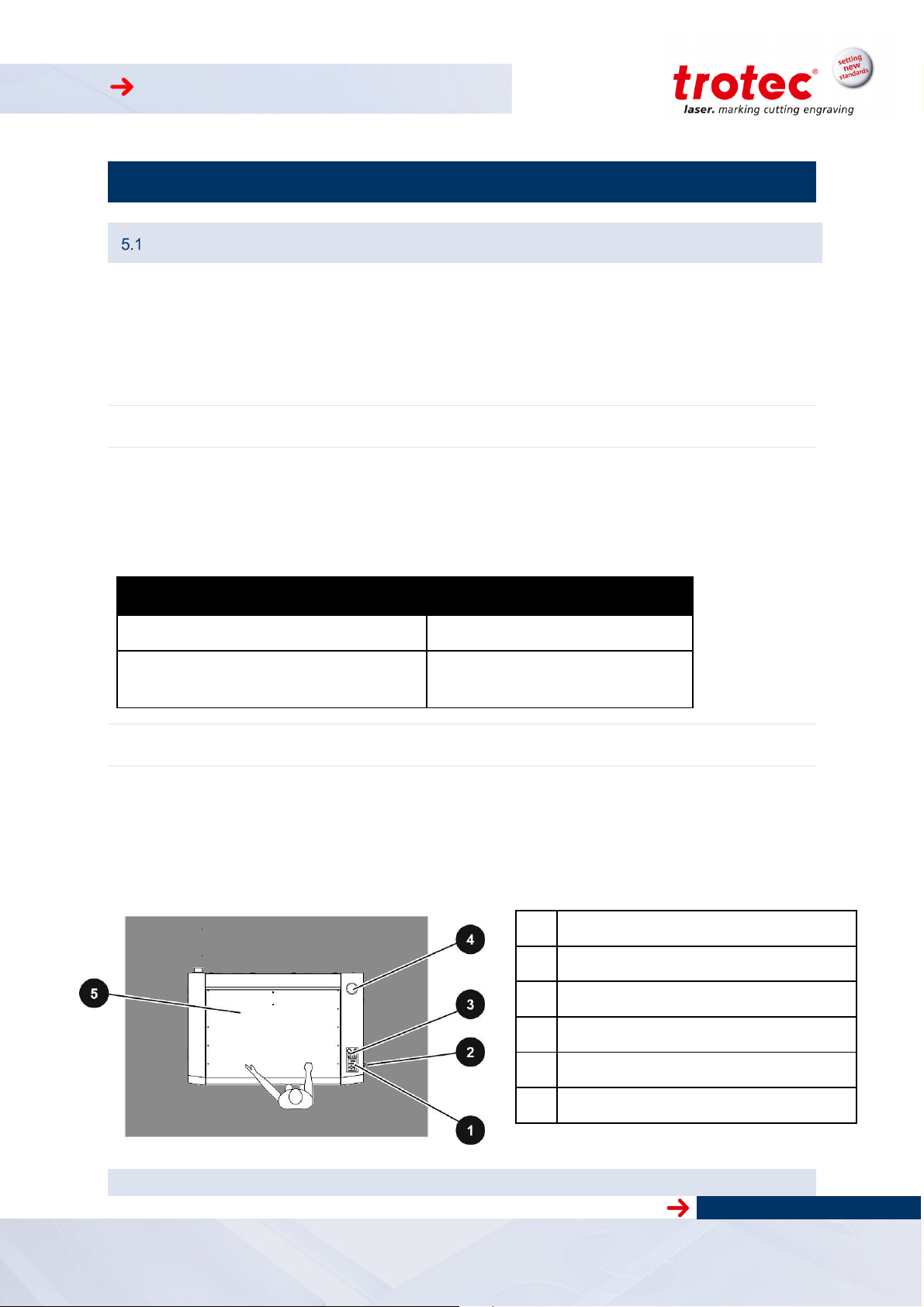
The safety zone is defined by the operator. Instructions and guidelines must be observed and followed!
Top view
EMERGENCY-OFF pushbutton
ON-OFF switch
Key switch
Warning lamp (option for pass-through)
Safety cover
Version 2.0 © TROTEC Produktions- u. Vertriebs GmbH
Technical changes reserved Freilingerstraße 99, A-4614 Marchtrenk
www.troteclaser.com
15 / 51
Page 16

SP 500
General Safety Instructions
5.2.1 General
Hazard due to improper use of the machine!
Improper use may lead to hazards and bodily injury and damage to assets.
•
Hazard due to disregard of safety instructions!
Improper activities at the machine may lead to death, bodily injury and/or damage
to the machine.
•
Hazard due to faulty behavior by untrained persons!
Improper activities at the machine may lead to death, bodily injury and/or damage
to the machine.
•
•
Hazard due to poor lighting, poor housekeeping and moisture!
Shadows, reflections and poor housekeeping increase the risk of an accident.
•
Hazard due to missing, defective or bypassed safety equipment or machine
parts!
Nonfunctioning or missing safety equipment or machine parts may lead to death,
bodily injury and/or damage to the machine.
•
•
Hazard due to operator error (especially in setup mode)!
Adjustment and control with insufficient knowledge of the machine may lead to
death, bodily injury and/or damage to the machine.
•
Hazard due to unsupervices operation of the machine!
Unsuperviced operation may lead to fire resulting in death, bodily injury and/or
damage to the machine.
•
Prohibit or prevent improper use.
Before startup read and observe the operating manual and safety
instructions!
Inform personnel about machine functions and potential risks and
record this in the training record.
Observe legal regulations related to operation of machines and accident prevention regulations.
Light the work area well, and always keep it clean and dry.
Carefully check safety equipment and machine parts for proper operation.
In case of a functional fault or defect, immediately take prescribed
actions to correct the problem
Before startup read and observe the operating manual and safety
instructions!
Never operate the machine without supervision!
.
Version 2.0 © TROTEC Produktions- u. Vertriebs GmbH
Technical changes reserved Freilingerstraße 99, A-4614 Marchtrenk
www.troteclaser.com
16 / 51
Page 17

SP 500
Hazard due to reckless actions!
Reckless actions may lead to death, bodily injury and/or damage to the machine.
Make sure that no personnel remain in the hazardous area or at the
•
machine.
Do not leave any foreign objects in the machine (tools, etc.).
•
Hazard due to operator error by unauthorized persons!
Adjustment and control of the machine by persons with inadequate knowledge of
machine operation may lead to death, bodily injury and/or damage to the machine.
Never inadvertently actuate the machine.
•
Turn the main switch off when the machine is not being used.
•
Hazard during faulty work process!
Deviations in machine processing and work results may be an indication of hazardous conditions (jammed product, loose guides, etc.).
Observe machine movements for proper operation and check
•
workresults on a regular basis.
In case of deviations, initiate prescribed actions.
•
Hazard due to premature actuation!
Premature actuation of the machine may lead to death, bodily injury and/or damage to the machine.
Do not reach into hazardous areas until you have turned off the
•
main switch and placed a service sign on it.
Hazard due to inadequate cleaning or functional checks!
Inadequate cleaning or functional checks result in machine damage.
Accumulation of dirt could impair mechanical functions.
Regularly check machine and connection lines for damage and
•
wear. In case of damage, immediately initiate prescribed actions.
Keep machine, handles and switches free of oil, grease, dirt and
•
moisture.
Hazard due to unsuitable tools!
The use of improper tools could result in a risk of bodily damage and/or damage to
the machine. Poor housekeeping leads to elevated accident risk.
Use proper tools for maintenance jobs.
•
Hazard due to missing machine signage!
The risk of machine operator error results from making incorrect assumptions.
Replace missing machine signage.
•
Hazard due to fault that cannot be corrected!
A fault that cannot be corrected may lead to injury and/or damage to the machine.
Turn off the machine and call customer service!
•
Version 2.0 © TROTEC Produktions- u. Vertriebs GmbH
Technical changes reserved Freilingerstraße 99, A-4614 Marchtrenk
www.troteclaser.com
17 / 51
Page 18

SP 500
Hazard due to improper disposal (waste, production materials)!
Improper disposal of waste materials can lead to environmental damage.
Recycle recyclable materials in separated and clean state. Dispose
•
of waste in accordance
Hazard due to inferior replacement parts or parts from other companies!
The use of inferior replacement parts or parts from other companies impairs machine safety and invalidates the supplied Conformity Declaration (CE).
Replace wear parts or damaged machine, safety or electrical com-
•
ponents with original replacement parts. Only use the accessories
or auxiliary
Hazard due to unsuitable work clothing or lack of protective equipment!
Risk of injury due to catching on machine parts, falling loads, inhalation of dust particles
and noise.
Wear suitable work clothing.
•
Wear safety glasses.
•
Wear ear protection (mandatory for noise levels >85 dB(A))
•
devices identified in the operating manual.
with applicable legal regulations.
Version 2.0 © TROTEC Produktions- u. Vertriebs GmbH
Technical changes reserved Freilingerstraße 99, A-4614 Marchtrenk
www.troteclaser.com
18 / 51
Page 19

SP 500
5.2.2 Laser Safety
There are versions of the machine for:
- Safety class 2
- Safety class 4 (With pass through option)
Class 2
The accessible laser radiation of Class 2 laser systems does not pose any hazard
for the skin. Any short-term radiation of the eyes also poses no risk due to the low
level output. In the event of longer, more intensive radiation, the eye is protected
by the natural lid reflex.
The SP 500 uses a Class 2 laser pointer. In order to prevent irritation of the eyes
during operation, the operator should not look directly at the laser source.
Diffuse reflections of the pilot laser are entirely harmless.
Class 4
Class 4 lasers pose the risk of direct radiation and indirect stray radiation and may
cause damage to both the skin and eyes.
Class 4 lasers also pose a fire and explosion hazard if used improperly and the radiation strikes any flammable material.
The operator is responsible to take all necessary protective measures to entirely
rule out the possible ignition or explosion of materials by the laser beam.
Class 4 lasers should be operated according to the following precautionary
measures among others:
The operator is obliged to appoint a trained Laser Protection Officer responsi-
ble for compliance with the relevant regulations.
The danger zone must be identified by installing warning lights and warning
signs outside the area.
The danger zone must be secured against unauthorised access.
The operator of a Class 4 laser system should always wear laser protection
glasses suitable for the wave length and output of the laser within the danger
zone.
An additional emission warning light should also be installed in a position visi-
ble to the operator to warn them of any emerging laser radiation.
Compliance with the points above does not absolve the operator from meeting the
relevant standards and guidelines for the operation of a Class 4 laser system.
Version 2.0 © TROTEC Produktions- u. Vertriebs GmbH
Technical changes reserved Freilingerstraße 99, A-4614 Marchtrenk
www.troteclaser.com
19 / 51
Page 20

SP 500
•
Hazard due to laser radiation without protective measures!
Lack of protective measures can result in:
- Burns on the cornea of the eyes,
- Skin burns, and
- Fire hazard for clothing
Never operate machine without protective equipment
•
Unapproved modification or disassembly of the laser is prohibited
•
Never manipulate the laser unit
•
Do not bypass the interlock system
Hazard in processing unapproved material!
Processing of materials not listed and approved in this operating manual is prohibited.
Processing medical technology and pharmaceutical products!
Trotec assumes no responsibility for any consequences or the suitability of laser
processing for any applications, especially those in the medical technology or
pharmaceutical fields.
Hazard when working with the cutting table!
If not all of the partition plates are used in the cutting table, there is a risk of fire due to
reflection of the laser beam.
Insert anti-reflective material beneath the partition plates.
www.troteclaser.com
Version 2.0 © TROTEC Produktions- u. Vertriebs GmbH
Technical changes reserved Freilingerstraße 99, A-4614 Marchtrenk
20 / 51
Page 21

SP 500
5.2.3 Transport Safety
Hazard of loads impacting persons or objects!
Falling, tipping or sliding loads may lead to death, bodily injury and/or damage to the
machine.
Never let loads impact persons.
•
Set up unloading station before lifting loads. Avoid unnecessarily long peri-
•
ods of lifting.
Do not lift loads until you have a clear view of the travel route. Choose travel
•
routes that are as unobstructed as possible.
Hazard due to lifting equipment operator error by untrained personnel!
Improper operation of lifting equipment may lead to death, bodily injury and/or damage
to the machine.
Operation of lifting equipment only by trained personnel.
•
Wear protective helmet, safety shoes and gloves.
•
Version 2.0 © TROTEC Produktions- u. Vertriebs GmbH
Technical changes reserved Freilingerstraße 99, A-4614 Marchtrenk
www.troteclaser.com
21 / 51
Page 22

SP 500
•
Secondary Risks
5.3.1 General
Hazard due to materials hazardous to health!
•
etc.), appropriate measures should be taken to avoid health hazards.
Hazard due to operator error!
Errors are possible even when the machine is operated properly following the functions
and sequences described in the operating manual. Such errors may lead to death, bodily injury and/or damage to the machine.
•
cated in the hazardous area.
In processing with or use (cleaning, etc.) of hazardous materials (toxic,
Do not initiate any work or adjustment activities while any personnel are lo-
Hazard due to add -on options or machines!
Adding on options or machines can lead to unknown risks and hazards.
Modifications made to the machine without approval by Trotec invalidates the
•
Conformity Declaration (CE) supplied with the product.
5.3.2 Crushing hazard
Hazard due to moving parts!
Reaching, stepping or leaning into the hazardous area may result in serious injury by
crushing body parts, severing fingers or the hand!
Do not initiate any work process on the machine while persons (helpers, etc.)
•
are located in the hazardous area of the machine.
Prohibit access to the hazardous area.
•
Wear suitable work clothing (no loose clothing, jewelry, or similar.).
www.troteclaser.com
Version 2.0 © TROTEC Produktions- u. Vertriebs GmbH
Technical changes reserved Freilingerstraße 99, A-4614 Marchtrenk
22 / 51
Page 23

SP 500
AGE TO THE EQUIPMENT
Signage
The warning and information labels are attached in such positions of the device that could
represent a source of danger during set-up and operation. Therefore, follow the
information on the labels. If labels are lost or damaged, they must be replaced
immediately.
Warning of
hand injury
Warning of
laser radiation
VISIBLE LASER RADIATION
DO NOT STARE INTO BEAM
CLASS 2 LASER PRODUCT
EN 60825-1:2003
CAUTION
INVISIBLE CLASS 4 LASER RADIATION
WHEN OPEN AND INTERLOCKS DEFEATED:
AVOID EYE OR SKIN EXPOSURE TO DI-
RECT OR SCATTERED RADIATION
CAUTION
INVISIBLE LASER RADIATION
WHEN OPEN AND INTERLOCKS DEFEATED:
AVOID EYE OR SKIN EXPOSURE TO DI-
RECT OR SCATTERED RADIATION
CAUTION
VISIBLE LASER RADIATION
WHEN OPEN DO NOT STARE INTO BEAM
Warning of
electrical power
Serial number
Warning of
fire
LASERDIODE
MAX. POWER <0.99mW cw
WAVELENGTH 655nm
INPUT POWER
380-400 VAC 50Hz
BEFORE OPEN
UNPLUG THE MACHINE FIRST
LIFTING POINTS
<- DO NOT LIFT HERE ->
NEVER OPERATE THE LASER SYSTEM
WITHOUT CONSTANT SUPERVISION:
EXPOSURE TO THE LASER BEAM MAY
CAUSE IGNITION OF COMBUSTIBLE MATE-
RIALS WHICH CAN CAUSE SEVERE DAM-
Version 2.0 © TROTEC Produktions- u. Vertriebs GmbH
Technical changes reserved Freilingerstraße 99, A-4614 Marchtrenk
www.troteclaser.com
23 / 51
Page 24

SP 500
2
Warning of
laser radiation
Warning of
electrical power
VISIBLE LASER RADIATION
DO NOT STARE INTO BEAM
CLASS 2 LASER PRODUCT
EN 60825-1:2003
INVISIBLE LASER RADIATION
AVOID EYE OR SKIN EXPOSURE TO
DIRECT OR SCATTERED RADIATION
CLASS 4 LASER PRODUCT
CAUTION
INVISIBLE CLASS 4 LASER RADIATION
WHEN OPEN AND INTERLOCKS
DEFEATED
AVOID EYE OR SKIN EXPOSURE TO
DIRECT OR SCATTERED RADIATION
CAUTION
VISIBLE LASER RADIATION
WHEN OPEN DO NOT STARE INTO BEAM
LASERDIODE
MAX. POWER <0.99mW cw
WAVELENGTH 655nm
CAUTION
INVISIBLE LASER RADIATION
WHEN OPEN AVOID EYE OR SKIN EXPOSURE
TO DIRECT OR SCATTERED RADIATION
CAUTION
VISIBLE AND INVISIBLE LASER RADIATION
WHEN OPEN AVOID EYE OR SKIN EXPOSURE
TO DIRECT OR SCATTERED RADIATION
INPUT POWER
380-400 VAC 50Hz
BEFORE OPEN
UNPLUG THE MACHINE FIRST
LIFTING POINTS
<- DO NOT LIFT HERE ->
www.troteclaser.com
Version 2.0 © TROTEC Produktions- u. Vertriebs GmbH
Technical changes reserved Freilingerstraße 99, A-4614 Marchtrenk
24 / 51
Page 25

SP 500
Lifting points
Lifting points
Transport - Storage – Setup
6 Transport – Storage - Setup
The machine has 4 rollers for moving it. All 4 feet must be fully screwed in before moving. The machine is also designed to be moved by forklift.
Forklift transport
Before moving the machine, perform the following on the base frame:
- Remove rear trim panel (1)
- Open the front door (2) with a 10mm Allen key
In addition, the following should be performed:
- Disconnect all attached lines.
- Fasten down all moving parts to stationary and sufficiently stable parts of the frame.
Lifting points
The machine may only be lifted and transported:
- Under the guidance of a 2nd person, and
- At the points identified.
After moving the machine, reinstall the rear trim panel (1) and close the door (2).
Version 2.0 © TROTEC Produktions- u. Vertriebs GmbH
Technical changes reserved Freilingerstraße 99, A-4614 Marchtrenk
www.troteclaser.com
25 / 51
Page 26

SP 500
Shipping conditions
-Remove table before shipping
CAUTION
When transporting outdoors, only transport in shipping vehicles with roofs or sufficient
weather protection.
CAUTION
Protect machine from shipping damage using tie-down straps, packaging materials and
sufficient gaps to other shipped goods.
- Ambient temperature for transport:
Minimum temperature +10 °C (+50 F)
Maximum temperature +40 °C (+104 F)
CAUTION
Handle machine and machine parts with care.
Do not place any heavy loads on top of the machine or machine parts.
Avoid harsh impacts.
Only lift at the specified points.
Take special care in transporting electronic components.
Unloading, inspection and damage reporting
After unloading:
1. Remove shipping packaging.
2. Dispose of packaging according to applicable waste disposal law.
3. Inspect machine and machine parts for shipping damage.
4. Check shipment for completeness.
In case of shipping damage or incomplete shipment:
1. Immediately document the details of the damage.
2. Also note the claim on shipping papers.
3. Photograph the damage.
4. Send report to TROTEC.
Storage conditions
- Store machine and machine parts in a dry area.
- Protect machine and machine parts from scratches.
- Store electronic components especially carefully in a packaged state.
- In case of longer term storage, protect exposed metal parts (e.g. oil the parts).
- Ambient temperature for storage:
Minimum temperature +10 °C (+50 F)
Maximum temperature +40 °C (+104 F)
Storage Location
In storage room or packaged with adequate weather protection.
The storage location must be free of caustic materials, vapors and combustible materials.
www.troteclaser.com
Version 2.0 © TROTEC Produktions- u. Vertriebs GmbH
Technical changes reserved Freilingerstraße 99, A-4614 Marchtrenk
26 / 51
Page 27

SP 500
Installation Site
- Weather-protected, roofed building with vehicular access
- Low dust environment
Properties of the installation site:
- Adequate lighting
- Uniform, level, horizontal and firm floor, planarity +/-5 mm
(+/-0.1969 inch), no special foundation required
- Load bearing capacity of base frame at least 300 kg/m2
(62 lbs/sq.ft.)
Installation site must:
- Be free of noisy electrical installations, hoses and pipe lines
- Have power supply that is free of fluctuations
- Be shielded from EMC
Ambient Conditions:
- Relative humidity: 40% to max. 70%
- Ideal room temperature: +15°C to +25°C (+59 F to +77F)
- Dust-free environment (2nd degree per IEC60947-1)
Space Requirements
Necessary Feed Lines
- Electrical
- Compressed air: Free of oil, water and dirt at max. 10 bar (145 psi)
- Gases (Neutrogen, Argon, protective gas, …)
Version 2.0 © TROTEC Produktions- u. Vertriebs GmbH
Technical changes reserved Freilingerstraße 99, A-4614 Marchtrenk
www.troteclaser.com
27 / 51
Page 28

SP 500
5
Setup
Unscrew all 4 feet until the distance
from rollers to floor is approx.
5 mm (0.2 inch)
Tools: Wrench 22mm and 24 mm
Align machine to horizontal level by
adjusting feet, and check with a fluid
level
www.troteclaser.com
Version 2.0 © TROTEC Produktions- u. Vertriebs GmbH
Technical changes reserved Freilingerstraße 99, A-4614 Marchtrenk
28 / 51
Page 29

SP 500
Item
Description
Item
Description
1
7
2
8
3
9
5
11
6
8
7 Connections
Electrical power
Connection cable: Exhaust
USB for PC
Gas 2
JobControl® Vision BNC connector
Cooling water inlet
RS-232 for PC
4
(necessary for JobControl® Vision/AlphaCam)
Exhaust: Working head
Compressed Air (Gas 1)
Version 2.0 © TROTEC Produktions- u. Vertriebs GmbH
Technical changes reserved Freilingerstraße 99, A-4614 Marchtrenk
10
Cooling water drain
Exhaust: Vacuum table
www.troteclaser.com
29 / 51
Page 30

SP 500
Item
Description
Item
Description
1
8
2
9
3
10
4
11
5
12
6
13
7
8 Machine view
Machine
Base frame with electronic components
Auto-focus sensor
Workpiece removal door
Main switch
Operator panel - keypad
Engraving head
Engraving table
Safety cover
X-Axis
Version 2.0 © TROTEC Produktions- u. Vertriebs GmbH
Technical changes reserved Freilingerstraße 99, A-4614 Marchtrenk
Warning lamp (option for pass-through)
Manufacturin label
Pass trough (option)
www.troteclaser.com
30 / 51
Page 31

SP 500
Item
Description
Item
Description
1
1
2
2
13
3
14
4
15
5
16
6
17
7
18
8
19
9
20
10
21
11
22
9
10 11 12
14
13
18 16
19
20
17
21 22
8
9 Operation
Key pad – Overview
Button: Gas 1
Button: Gas 2
Button: Air assist (internal)
Indicator: Compressed air, Voltage (AC, DC)
Key switch
Indicator: Interlock open/close
Indicator: Water cooling on/off
EMERGENCY STOP push button
Button: Standby
LED status indicator: Laser busy
Button: Stop
Button: Start/Pause/Repeat
Status display
Button: “Shift” for 2nd function key level
Button: Exhaust on/off
Button: Working head to left/right
Button: Working head forward/backward
Button: Work table upward
Button: Work table downward
Button: Home
Manometer for gas pressure
Pressure regulator
www.troteclaser.com
Version 2.0 © TROTEC Produktions- u. Vertriebs GmbH
Technical changes reserved Freilingerstraße 99, A-4614 Marchtrenk
31 / 51
Page 32

SP 500
1 Gas 1
2 Gas 2
3 Air Assist
4 Compressed air, Voltage (AC, DC)
indicator
5 Key switch
6 Interlock on/off indicator
7 Cooling on/off indicator
8 EMERGENCY
STOP
push
button
8
Key pad – Description
Gas 1 on/off key
Gas 2 on/off key
Switch on/off the
Lights in following conditions:
Compressed air missing
AC-Voltage failure (L1, L2, L3, N)
DC-Voltage failure (power supplies)
Interlock indicator lights when the machine is turned on, and:
Guard door or door is open
Cover plate is not installed
If the Interlock Indicator is unlit, the machine is ready for production.
Pressing this button shuts the machine down completely.
The EMERGENCY OFF pushbutton must be unlocked to start up the machine again.
air assist
Version 2.0 © TROTEC Produktions- u. Vertriebs GmbH
Technical changes reserved Freilingerstraße 99, A-4614 Marchtrenk
www.troteclaser.com
32 / 51
Page 33

SP 500
STANDBY
LED status indicator: Laser b
usy
STOP
Start/Pause/Repeat
Status Display
9
10 11 12
14
13
18 16 19
20
17
9
If the Standby button is pressed while the Z- axis is in an automatic move (e.g. autofocus), the
Standby mode is entered after finishing the Z- axis- move (Z- axis move can be stopped by
pressing any of the Z- axis keys).
10
Indicates, that a laser beam is currently being emitted.
11
By pressing this button, the actual process running will be stopped.
12
Pressing the button with no Job running the actual Jobs positioned on the selected plate in JobControl are started.
Used to pause the current working process (key lights up). As soon as the last processing command is finished, the motion system stops.
If this key is pressed a second time, the key illumination goes off, the interrupted working process is continued.
Pressing the button after a Job is finished will repeat the actual Jobs positioned on the selected
plate in JobControl. The Jobs will reset automatically.
13
Indicates the current status of the device.
green permanent light / Pause mode 13 Data available in the machine
Switches the device into Standby mode (Laser ready, illumination off) - key lights
up.
By pressing the key again the device is switched back to Ready mode.
green, flashing slowly (0.5 Hz) 13 Machine is ready
green, flashing fast (2 Hz) 13 Cover has been opened
red permanent light 13 Laser beam is being emitted
green/red flashing alternately 13+10 Cover open during switch-on process,
simultaneously acoustic signal - no ref-
erencing
Version 2.0 © TROTEC Produktions- u. Vertriebs GmbH
Technical changes reserved Freilingerstraße 99, A-4614 Marchtrenk
www.troteclaser.com
33 / 51
Page 34

SP 500
“Shift” for 2
nd
function key leve
l
Exhaust on/off
Positioning keys Z
14
For additional Operations. When this key is pressed together with the following keys, the functions indicated are activated:
Exhaust (5): Air assist on/off
Positioning keys X/Y/Z (2): These keys drive the laser head to
the end position
15
Used to manually switch the exhaust system on and off.
The key illumination shows the status of the exhaust system. When the key is illuminated, the
exhaust system is switched on.
After completing the engraving process, the exhaust system can only be switched off after
some seconds (follow-up time).
Air assist is switched on/off by simultaneously pressing these keys:
“Shift” for 2nd function key level (14)
And
Exhaust on/off (9)
16
17
Use these positioning keys to move the table manually.
When both keys are pressed simultaneously, the material is focused automatically.
Before the autofocus- move is started, the head is moved backward in line with the light barriers. If the light barrier is broken, e.g. by an air assist nozzle, the upward move will be suppressed to prevent a collision between the nozzle and the table.
By pressing the "Shift" key and a Z- positioning key an automatic move to the corresponding
end- positions is performed:
Shift + Down: the table moves down to the lowest possible position
Shift + Up: the table moves up to the autofocus- position.
Note: Shift + Up will cause the head moving backwards to the light barriers (according simultaneous pressing of both z-keys).
If any of positioning keys X and Y is pressed, no moves in Z are possible.
An automatic move of the Z- axis can be stopped by pressing of the positioning keys
(1 or 2).
When pressing one of these two keys the working table moves in Z direction (upwards or downwards).
The Autofocus option might not work on transparent materials or materials which
are not flat.
Bear in mind that defects from head crashes (working head hits material or working
table) are NOT warranted.
Version 2.0 © TROTEC Produktions- u. Vertriebs GmbH
Technical changes reserved Freilingerstraße 99, A-4614 Marchtrenk
www.troteclaser.com
34 / 51
Page 35

SP 500
Positioning keys X/Y
HOME
Manometer for gas pressure
Pressure regulator
18
Use the positioning keys to manually move the lens holder into the indicated directions.
19
When you press two keys simultaneously, the lens holder moves diagonally.
When you press the "Shift" key and one of the positioning keys simultaneously, a
movement to the corresponding end position is performed.
If all panels are closed, the movement is done with the maximum velocity, if
opened, the speed is 1/4th of the maximum.
While the Z- axis is in movement (e.g. autofocus), no cursor moves in X and Y axis
are performed.
The Autofocus option might not work on transparent materials or materials which
are not flat.
20
Pressing this button will change the machines home position temporary (Home-move to this position)
Bear in mind that defects from head crashes (working head hits material or working
table) are NOT warranted.
21
22
This is used to adjust the required gas pressure of the gas used. The pressure setting is displayed on the: manometer for gas pressure.
Version 2.0 © TROTEC Produktions- u. Vertriebs GmbH
Technical changes reserved Freilingerstraße 99, A-4614 Marchtrenk
www.troteclaser.com
35 / 51
Page 36

SP 500
Workpiece Removal Door
Open door (1) by pulling forward on the
two handles
Remove the workpieces with the broom (2)
The bracket (3) for the broom has 3 magnets
and is mounted on the side of the machine
Door must be closed during
laser operation.
Pass-through opening (optional)
Open the pass-through by folding down door (4)
Insert bypass jumper in socket (5) for pass-
through.
Do not reach into opening
during operation.
Warning of laser radiation
Class 4. Take all necessary
measures (compare section
5.2.2Laser Safety)
Version 2.0 © TROTEC Produktions- u. Vertriebs GmbH
Technical changes reserved Freilingerstraße 99, A-4614 Marchtrenk
www.troteclaser.com
36 / 51
Page 37

SP 500
Exhaust System
Trotec advises to use the Atmos Duo Plus for the SP 500.
Depending on the type of table installed in the machine the exhaust requirements and recommended
Trotec exhaust systems for standard applications are:
Head Exhaust (45mm) 50 m³/h 5300 Pa
Vacuum table (75mm) 250 m³/h 3900 Pa
Cutting table (75mm) 350 m³/h 1500 Pa
Standard table Not applicable (Table Exhaust inactive)
Monitoring point for flow-rate and pressure is at the exhaust port at the laser machine. Pressure loss
by hoses / pipes or filter parts of the exhaust has to be determined and additionally calculated when
selecting a proper exhaust.
If only a Cutting table is installed, a VENT 3000 would be sufficient
The laser may only be operated with properly installed and operating exhaust system.
Fumes and dust created during cutting or engraving have to be exhausted properly.
Some materials when cut or engraved can produce fumes that are hazardous in concentrated amounts.
Damage to the system caused by the use of no or improper extraction equipment will
not be covered by warranty.
The life time of optics and mechanical components will be reduced by fumes and dust
accumulating in the machine. This will be avoided by a capable exhaust system.
The cutting quality will be reduced by fumes and dust accumulating in the machine.
This will be avoided by a capable exhaust system.
The laser power interacting with the work-piece will be reduced by fumes and dust accumulating in the machine. This will be avoided by a capable exhaust system.
Atmos
Flow rate Pressure
The exhaust power which is available for the application will be reduced by e.g. bending, small hose diameters and long hoses.
Therefore, avoid bending, keep hoses as short as possible and use hoses with diameters as large as possible.
Applications generating large amounts of dust or fumes may require a stronger exhaust system.
Also the use of separate exhaust systems for head and table exhaust may be necessary.
It is absolutely necessary to consult your distributor in such cases.
Mono
Atmos
Duo
Vent
3000
Vent
HP
.
www.troteclaser.com
Version 2.0 © TROTEC Produktions- u. Vertriebs GmbH
Technical changes reserved Freilingerstraße 99, A-4614 Marchtrenk
37 / 51
Page 38

SP 500
Tables
9.6.1 Base Frame (with/without lamellas)
The frame is permanently attached to the ma-
chine’s Z axis.
The following individual table variants are
placed on it (with our without lamellas):
- Engraving table
- Vacuum table
- Cutting table
The table is secured in the center by
mounted latching pins.
It is easy to remove parts that have fallen into
the frame via a door.
To do this, the table must be driven to
its lowermost position.
The “Rotary engraving attachment” option is
placed directly in the base frame.
9.6.2 Engraving Table (Standard table)
The engraving table rests on the base frame and
is supported by additional braces there.
The engraving table is only for engraving heavy
objects, such as metals, marble, granite, glass,
heavy wood and acrylic parts.
Two swiveling handles (1) make it easier to lift
out the engraving table. To use them, swivel the
handles (1) upward.
Version 2.0 © TROTEC Produktions- u. Vertriebs GmbH
Technical changes reserved Freilingerstraße 99, A-4614 Marchtrenk
www.troteclaser.com
38 / 51
Page 39

SP 500
Hazard when working with the cutting table!
9.6.3 Vacuum Table
The vacuum table rests on the base frame and
•
is supported by additional braces there.
l
The vacuum table is only intended for engrav-
•
ing
and/or cutting thin and lightweight materials
such
as films, plastic laminates, veneers, thin sheets
of wood, paper, cardboard, and similar.
l
The entire surface of the vacuum table must
•
be covered to ensure the maximum vacuum
effect
l
Two swiveling handles (1) make it easier to
•
lift out the engraving table
To use them, swivel the handles (1) upward.
9.6.4 Cutting Table
f not all of the partition plates are used in the cutting table, there is a fire
hazard due to reflection of the laser beam.
Insert an anti-reflective material beneath the partition plates
It is not allowed to place Workpieces into the baseframe without a Table attachment (e.g. Standard-, Vacuum- or Cutting Table).
This is important so no bending on the frame and impairment of the exhaust function is
possible
•
l
To ensure even better contact (2), the
“Contact” option is recommended.
The cutting table rests on the base frame
•
and is supported by additional braces there.
•
Specially shaped air guides are used in the
cutting table. This ensures that parts falling into
the frame are not damaged by the laser.
Custom made acrylic bars may also be used.
Version 2.0 © TROTEC Produktions- u. Vertriebs GmbH
Technical changes reserved Freilingerstraße 99, A-4614 Marchtrenk
www.troteclaser.com
39 / 51
Page 40

SP 500
Lenses
The following lenses are available for SP 500.
2“
black
# 20352
2,5“
silver
# 15410
2,5“ clearance
bright green
# 30659
3.75“ rotary
violett
# 30645
5“
blue
# 15411
www.troteclaser.com
Version 2.0 © TROTEC Produktions- u. Vertriebs GmbH
Technical changes reserved Freilingerstraße 99, A-4614 Marchtrenk
40 / 51
Page 41

SP 500
Start of Operation
Enable machine with key (1)
Check whether EMERGENCY-OFF
pushbutton (2) is unlocked
Turn on main switch (3)
Close the top lid. Wait for reference move.
Drive the laser head to its forward-most position
Key
Clean lens (4), reinstall and secure
Install nozzle (5)
Drive the laser head to reference point by
simultaneously activating these
Keys
Version 2.0 © TROTEC Produktions- u. Vertriebs GmbH
Technical changes reserved Freilingerstraße 99, A-4614 Marchtrenk
www.troteclaser.com
41 / 51
Page 42

SP 500
Drive the work table downward
Key
Place material on table
Focusing the laser
Place focus tool (6) on laser head
Drive the work table upward until focus tool drops tilts
Key
Machine is now ready for production.
The Autofocus option might not work on transparent materials or materials which are not
flat.
Bear in mind that defects from head crashes (working head hits material or working table)
are NOT warranted.
Version 2.0 © TROTEC Produktions- u. Vertriebs GmbH
Technical changes reserved Freilingerstraße 99, A-4614 Marchtrenk
www.troteclaser.com
42 / 51
Page 43

SP 500
3 Maintenance
Cleaning optics on the Laser Head
Cleaning the mirror (1):
Loosen both screws (2)
•
Remove mirror mount (3)
•
Check mirror (1) for damage
•
Clean mirror (1) with cleaning liquid and cleaning
•
tissue
Check mirror (1) once again for damage
•
Reinstall mirror mount (3) and secure with
•
two screws (2)
Cleaning the 5” lens (4):
Unscrew 5“ lens (4)
•
Check 5“ lens (4) for damage
•
Clean both sides of 5“ lens (4) with cleaning liq-
•
uid and cleaning tissue
l
Check 5“ lens (4) once again for damage
•
Cleaning lenses (5) and (6)
Loosen lenses (5) and (6) by screwing
•
retainer inward (7)
Remove lenses (5) and (6)
•
Check lenses (5) and (6) for damage
•
Clean both sides of lenses (5) and (6) with clean-
•
ing liquid and cleaning tissue
Check lenses (5) and (6) once again for damage
•
•
Insert lenses (5) and (6) and clamp with
retaining ring (7)
Version 2.0 © TROTEC Produktions- u. Vertriebs GmbH
Technical changes reserved Freilingerstraße 99, A-4614 Marchtrenk
www.troteclaser.com
43 / 51
Page 44

SP 500
Cleaning the Mirrors
•
Unlock cover (1)
- Tool: Metric Allen wrench No. 10
•
Remove cover (1) by pulling on the handles
3 mirrors (2) must be cleaned:
•
Loosen both screws (3)
•
Remove mirror mount (4)
•
Check mirror (5) for damage
•
Clean mirror (5)
•
Cleaning liquid and cleaning tissue
•
Check mirror (5) once again for damage
•
Put on mirror mount (4) and secure with
two screws (3)
Version 2.0 © TROTEC Produktions- u. Vertriebs GmbH
Technical changes reserved Freilingerstraße 99, A-4614 Marchtrenk
www.troteclaser.com
44 / 51
Page 45

SP 500
Maintenance plan
daily weekly monthly yearly
Laser
Lens, mirror #4 Check
Cleaning if
required
mirrors #1...3
Processing table and rulers
Entire working area –
Cleaning
Cleaning
general cleaning
Exhaust System
Bag filter
Filter mat
According to the operation manual
Particle filter
Activated carbon filter
Cooling System
Pump filter
Condenser heater
According to the operation manual
Cooling agent
Pump
Check
Cleaning if
required
of the exhaust system
of the exhaust system
For detailed information on the maintenance activities on exhaust and cooling systems please refer to the respective manuals.
www.troteclaser.com
Version 2.0 © TROTEC Produktions- u. Vertriebs GmbH
Technical changes reserved Freilingerstraße 99, A-4614 Marchtrenk
45 / 51
Page 46

SP 500
10 Appendix
EC – Declaration of Conformity
(Machine directive 2006/42/EG, appendix II A)
Manufacturer
TROTEC Produktions u. Vertriebs GmbH.
Linzer Straße 156,
A-4600 Wels
Authorized person for the compilation of technical documentation
Gerhard KREMPL, TROTEC Produktions u. Vertriebs GmbH., Linzer Straße 156, A-4600 Wels
We hereby certify that
in its conception, construction and form put by us into circulation is in accordance with all the relevant
essential health and safety requirements of the EC machinery directive 2006/42/EEC.
Further valid guidelines/regulations for the product
2006/95/EG Low Voltage Directive
2004/108/EG EMC Guideline
Applied harmonized standards
- EN ISO12100 Machine Safety
- EN 60335-1/2007 Safety of Household and similar Appliances
- EN 55014-1/2006, EN 55014-2/1997 Electromagnetic Compatibility
- EN 60204-1 Machine Safety – electr. Equipment
- EN 60825-1/2007, EN 60825-4/2006 and EN 60825-14/2006 Safety of Laser Equipment
- EN 55022/2008, EN 55024/2003 Electromagnetic Compatibility
Place, Date:
Wels, 30.03.2011
Personal data of the signer:
Stephan FAZENY, Head of Research and Development
Signature:
:
:
Speedy 500
Modell N° 8014 Speedy 500 C40/50/60/70/80/90/100/110/120/200
:
:
Version 2.0 © TROTEC Produktions- u. Vertriebs GmbH
Technical changes reserved Freilingerstraße 99, A-4614 Marchtrenk
www.troteclaser.com
46 / 51
Page 47

SP 500
Acceptance report
Dear customer!
Please check applicable items:
Machine parts checked for shipping damage
We request your confirmation of
properly completed transfer of the
machine
Machine parts checked against delivery note
Setup of the machine discussed
Startup of the machine discussed
Operation of the machine discussed
Maintenance of the machine discussed
Electrical voltage checked
Please transmit a copy of this document – filled out and signed by an
authorized company representative
Safety Instructions discussed
Trial run performed
Deficiencies determined
– to an employee of our sales affiliate for forwarding to the manufacturer.
The machine with the
Thank you very much.
machine designation: SP 500
has been checked according to the listed items and has
been transferred properly.
City, Date
Company stamp / Signature
www.troteclaser.com
Version 2.0 © TROTEC Produktions- u. Vertriebs GmbH
Technical changes reserved Freilingerstraße 99, A-4614 Marchtrenk
47 / 51
Page 48

SP 500
Training Verification Form
Employee/Trainee:
Trainer:
Date of Training:
The above mentioned Employee received instruction on the operation of the SP 500 Lasersystem.
Especially the following topics are covered:
- Machine Function
- Danger Area
- Warnings
- Position
Emergency-OFF
Button
- Personal Protective Equipment
- Operating Facilities
- Work Flow
- Setting-up
- Taking into Service and Shutdown
- Announcement of unexpected working result and the resulting procedure
- Announcement of Failure and instituting Procedure
- Responsibility on remedial measure
- Operation Manual and its depository for inspection
............................................................... ...............................................................
Signature of Trainer Signature of Trainee
www.troteclaser.com
Version 2.0 © TROTEC Produktions- u. Vertriebs GmbH
Technical changes reserved Freilingerstraße 99, A-4614 Marchtrenk
48 / 51
Page 49

SP 500
Response Form
If you face any trouble with the machine, please provide the following information and add the service
file (procedure on how to create a service file, is described on the following pages).
Date
Machine Details
Contact Details
Serial Number First Name
JobControl Version Last Name
Driver Version Country
Layout Software Phone
Firmware Version Email
Problem Description
Does an error message show up on the PC, if so which one?
What happened before the error appeared? (Thunder & Lightning, Windows-Update,…)
What was tried to solve the problem?
Please send the information to your sales representative or to techsupport@troteclaser.com.
Version 2.0 © TROTEC Produktions- u. Vertriebs GmbH
Technical changes reserved Freilingerstraße 99, A-4614 Marchtrenk
www.troteclaser.com
49 / 51
Page 50

SP 500
How to create a Service File
1. Start JobControl.
2. Position the job (which possibly caused a failure) on the plate.
This can be done by either
a) double clicking on the appropriate job name in the queue
b) dragging the job onto the plate using the mouse
c) selecting the job by clicking on the job name in the queue and then clicking on the icon
"Position Job" .
3. Run the job and leave the job on the plate.
4. Go to “Settings” > “Create Service File”.
5. The window „Save Service File to“ shows up. Please select a directory to save the file and
click on „Save“.
Version 2.0 © TROTEC Produktions- u. Vertriebs GmbH
Technical changes reserved Freilingerstraße 99, A-4614 Marchtrenk
www.troteclaser.com
50 / 51
Page 51

SP 500
6. The window „Add Layout File“ appears. Please select the layout file, which was sent to JobControl and possibly caused a failure (e.g.: a CorelDraw file, Photoshop file, AutoCAD file,…).
Now click on „Open“.
7. The following window confirms, that the service file (ServiceLog.txt) was created successfully
and shows the path where it was saved.
8. Please forward the service file "SeviceLog.txt" together with a screenshot of e.g. the error
message and detailed description to your sales representative or to techsupport@trotecla-
ser.com.
Version 2.0 © TROTEC Produktions- u. Vertriebs GmbH
Technical changes reserved Freilingerstraße 99, A-4614 Marchtrenk
www.troteclaser.com
51 / 51
 Loading...