

trotec laser 1500 Operation Manual
SP1500 Operation Manual

SP1500 Operation Manual
Copyright© by Trotec Produktions und Vertriebs Ges.m.b.H.
All rights reserved.
Anyone who reproduces, copies or distributes this document, or parts of it, without the approval
of Trotec Produktions und Vertriebs Ges.m.b.H. is subject to prosecution.
We do not assume liability for any errors contained in this documentation.
We reserve the right to make technical changes.
Trotec Produktions und Vertriebs Ges.m.b.H.
Linzer Strasse 156,
A-4600 Wels, OÖ.
AUSTRIA
Tel.: +43-(0)7242-239-0
Fax: +43-(0)7242-239-7380
trotec@troteclaser.com
www.troteclaser.com
23/08/2010 Trotec Produktions- und Vertriebs GmbH_Linzer Strasse 156, A-4600 Wels, Austria, Technical Support 2 / 47
tel_+43 (0)7242 239-7000, fax_+43 (0)7242 239-7380, mailto: techsupport@troteclaser.com

SP1500 Operation Manual
Table of Contents
Table of Contents
1 Manufacturing label........................................................................................................5
2 Product Components .....................................................................................................6
3 Preface.............................................................................................................................7
3.1 General.................................................................................................................................... 7
3.2 Product Tracking ..................................................................................................................... 8
4 Technical Data ................................................................................................................9
4.1 General Description................................................................................................................. 9
4.2 Intended Use ........................................................................................................................... 9
4.3 Dimensions............................................................................................................................ 10
4.4 Mechanical Design ................................................................................................................ 11
4.5 Control System...................................................................................................................... 11
4.6 Laser Tubes .......................................................................................................................... 11
4.7 Laser Safety .......................................................................................................................... 12
4.8 Ambient Conditions ............................................................................................................... 12
4.9 Options .................................................................................................................................. 12
4.10 Electrical Connection........................................................................................................... 13
4.10.1 Electrical connection for laser system .......................................................................... 13
4.10.2 Electrical connection for water cooling (option) ............................................................ 13
4.11 Materials.............................................................................................................................. 14
5 Safety.............................................................................................................................15
5.1 Safety Instructions................................................................................................................. 15
1.1 Intended user group........................................................................................................... 15
1.2 Operating instructions / Safety equipment......................................................................... 15
5.2 General Safety Instructions ................................................................................................... 16
2.1 General .............................................................................................................................. 16
2.2 Laser.................................................................................................................................. 19
2.3 Transport ........................................................................................................................... 20
5.3 Secondary Risks ................................................................................................................... 21
3.1 General .............................................................................................................................. 21
3.2 Crushing hazard ................................................................................................................ 21
5.4 Signage ................................................................................................................................. 22
6 Transport - Storage - Setup .........................................................................................24
6.1 Forklift transport .................................................................................................................... 24
6.2 Shipping conditions ............................................................................................................... 26
6.3 Unloading, inspection and damage reporting........................................................................ 26
6.4 Storage conditions................................................................................................................. 26
6.5 Storage Location ................................................................................................................... 26
6.6 Installation Site...................................................................................................................... 27
6.7 Space Requirements............................................................................................................. 27
6.8 Necessary Feed Lines........................................................................................................... 27
6.9 Setup ..................................................................................................................................... 28
6.10 Connections ........................................................................................................................ 29
6.10.1 Cooling System............................................................................................................. 30
7 Machine view................................................................................................................. 31
8 Operation.......................................................................................................................32
8.1 Key pad – Overview .............................................................................................................. 32
23/08/2010 Trotec Produktions- und Vertriebs GmbH_Linzer Strasse 156, A-4600 Wels, Austria, Technical Support 3 / 47
tel_+43 (0)7242 239-7000, fax_+43 (0)7242 239-7380, mailto: techsupport@troteclaser.com

SP1500 Operation Manual
Table of Contents
8.2 Key pad – Description ........................................................................................................... 33
8.3 Workpiece Removal Door ..................................................................................................... 36
8.4 Tables.................................................................................................................................... 37
8.4.1 Cutting Table (Standard Table) ...................................................................................... 37
8.4.2 Vacuum Table................................................................................................................. 37
8.5 Operation............................................................................................................................... 38
9 Maintenance..................................................................................................................39
9.1 Cleaning optics on the Laser Head ....................................................................................... 39
9.2 Cleaning the Mirrors .............................................................................................................. 40
9.3 Maintenance plan .................................................................................................................. 41
10 Appendix .....................................................................................................................42
10.1 EU – Declaration of conformity............................................................................................ 42
10.2 Acceptance report ............................................................................................................... 43
10.3 Acceptance report ............................................................................................................... 44
10.4 Response Form................................................................................................................... 45
10.5 How to create a Service File ...............................................................................................46
23/08/2010 Trotec Produktions- und Vertriebs GmbH_Linzer Strasse 156, A-4600 Wels, Austria, Technical Support 4 / 47
tel_+43 (0)7242 239-7000, fax_+43 (0)7242 239-7380, mailto: techsupport@troteclaser.com
SP1500 Operation Manual
Manufacturing label
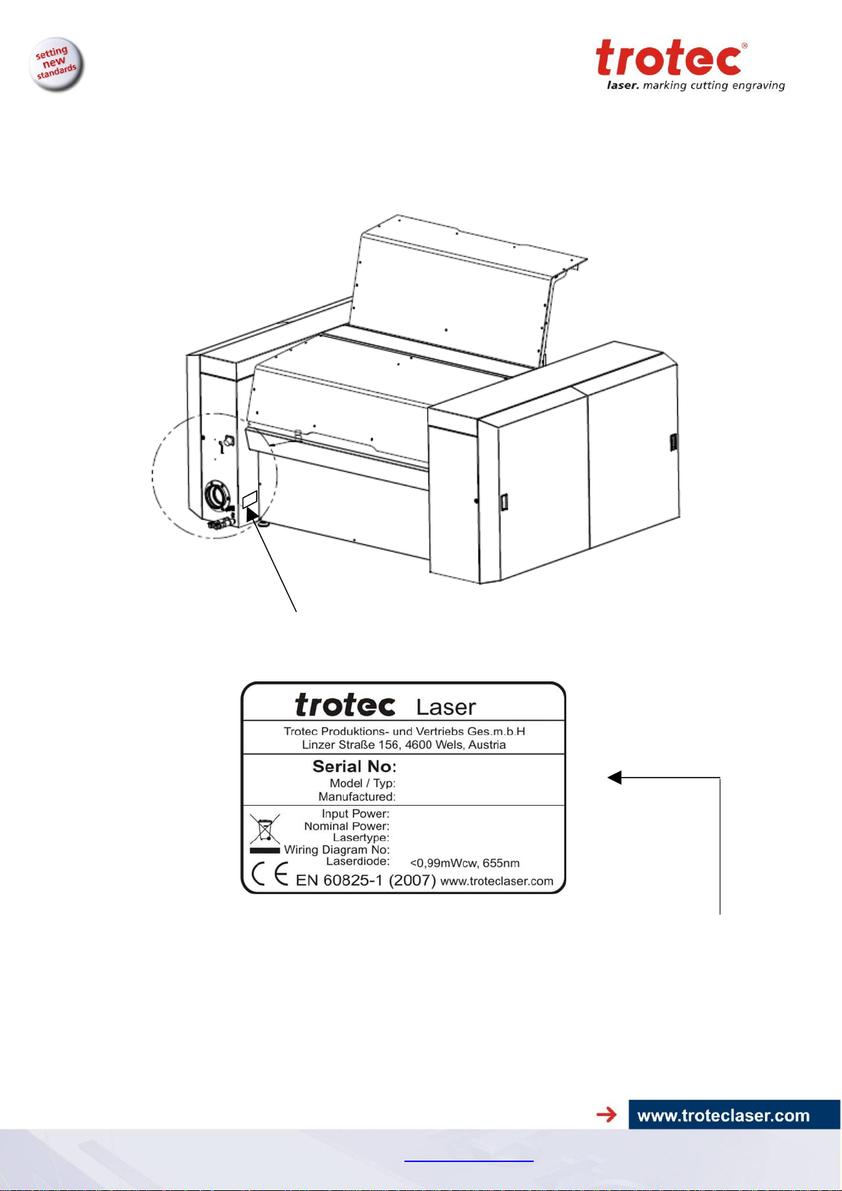
1 Manufacturing label
You find the manufacturing label with the CE-sign on the back side of the machine.
Enter the serial number, model and year of manufacture from the manufacturing label here.
This information is important for troubleshooting problems with the product and for ordering
replacement parts.
23/08/2010 Trotec Produktions- und Vertriebs GmbH_Linzer Strasse 156, A-4600 Wels, Austria, Technical Support 5 / 47
tel_+43 (0)7242 239-7000, fax_+43 (0)7242 239-7380, mailto: techsupport@troteclaser.com
SP1500 Operation Manual
)
Product Components
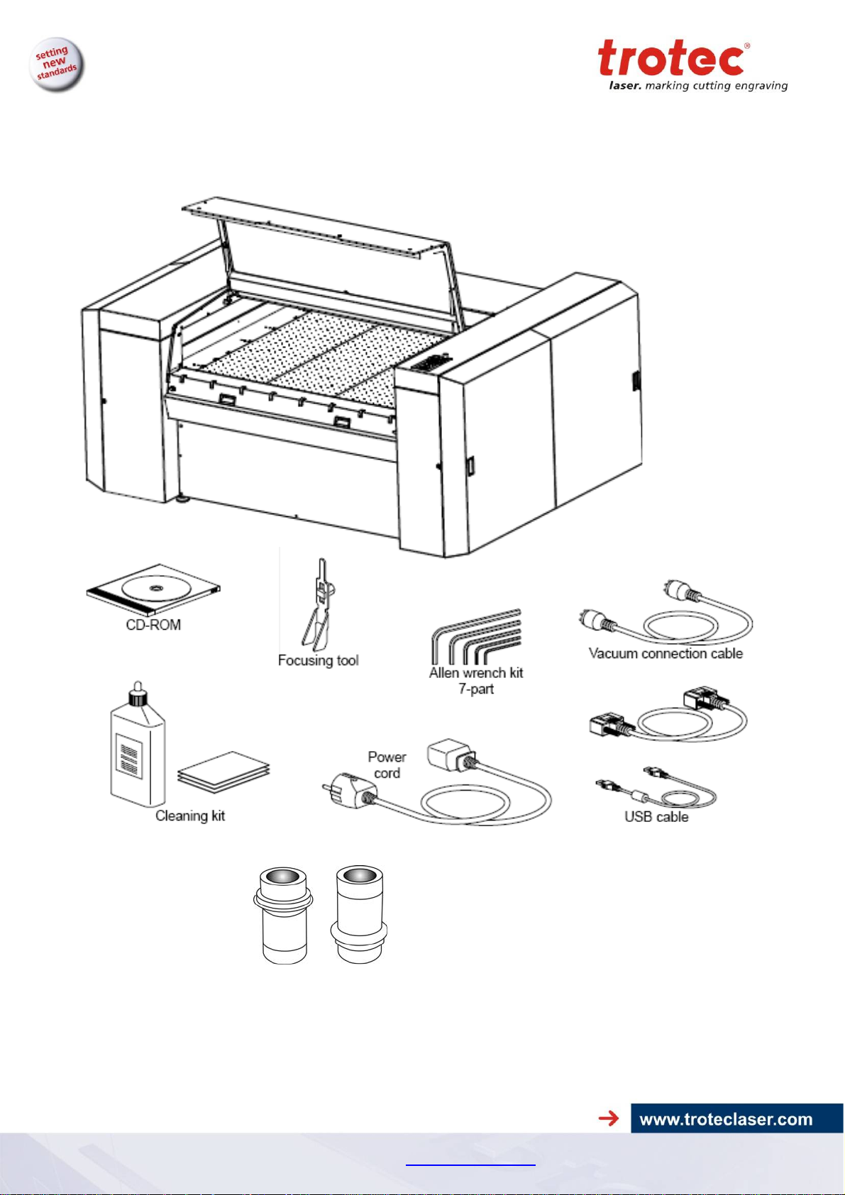
2 Product Components
RS232-cable (TroCAM / iCUT
Lenses 2.5“ / 5“
(7.5“ optional)
23/08/2010 Trotec Produktions- und Vertriebs GmbH_Linzer Strasse 156, A-4600 Wels, Austria, Technical Support 6 / 47
tel_+43 (0)7242 239-7000, fax_+43 (0)7242 239-7380, mailto: techsupport@troteclaser.com

SP1500 Operation Manual
Preface
3 Preface
3.1 General
This operating manual is intended to simplify the following for you:
• Learning about the machine, and
• Utilizing the machine’s capabilities according to its
intended use.
The operating manual contains important notes on how to operate
the machine:
Safely,
•
Properly, and
•
Economically
•
Following the operating instructions helps you to:
Avoid hazards and risks,
•
Minimize repair costs and downtimes, and
•
Increase the reliability and service life of your machine.
•
23/08/2010 Trotec Produktions- und Vertriebs GmbH_Linzer Strasse 156, A-4600 Wels, Austria, Technical Support 7 / 47
tel_+43 (0)7242 239-7000, fax_+43 (0)7242 239-7380, mailto: techsupport@troteclaser.com

SP1500 Operation Manual
Preface
3.2 Product Tracking
We have a legal duty to track our products after delivery to our
customers.
In particular, this relates to:
This information serves as a basis for potential corrections and/or
changes to the product, and it is therefore of great interest to us.
We request that you inform us of any such events and offer us
your recommendations. This is the only way that we can improve
our products as necessary, and to make them as safe and reliable
as possible.
• Recurring faults in functions
• Anything that is unclear, e.g. in operation, maintenance
or instructions
• Any accidents that occur
• Other unusual observations
• Recommendations for improvement, requests
23/08/2010 Trotec Produktions- und Vertriebs GmbH_Linzer Strasse 156, A-4600 Wels, Austria, Technical Support 8 / 47
tel_+43 (0)7242 239-7000, fax_+43 (0)7242 239-7380, mailto: techsupport@troteclaser.com

SP1500 Operation Manual
Technical Data
4 Technical Data
4.1 General Description
All electronic components are integrated in the machine.
All necessary connections are made on the back side of the SP1500.
Controls for the SP1500 are located on the keypad.
The SP1500 is equipped with an interlock safety system. When
the interlock is activated, only setup tasks can be performed on the
SP1500.
The machine has a manual table changing system that enables use of the
optimal table for specific jobs.
4.2 Intended Use
The Trotec SP1500 is designed for engraving and cutting of the
materials listed in this document.
23/08/2010 Trotec Produktions- und Vertriebs GmbH_Linzer Strasse 156, A-4600 Wels, Austria, Technical Support 9 / 47
tel_+43 (0)7242 239-7000, fax_+43 (0)7242 239-7380, mailto: techsupport@troteclaser.com
SP1500 Operation Manual
Technical Data
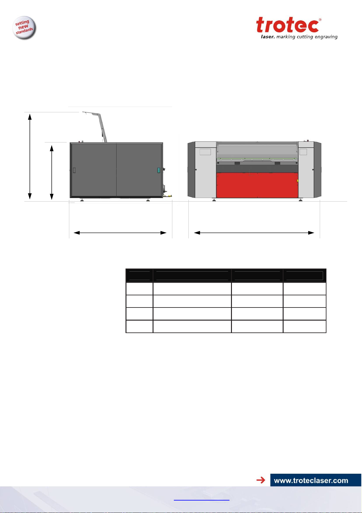
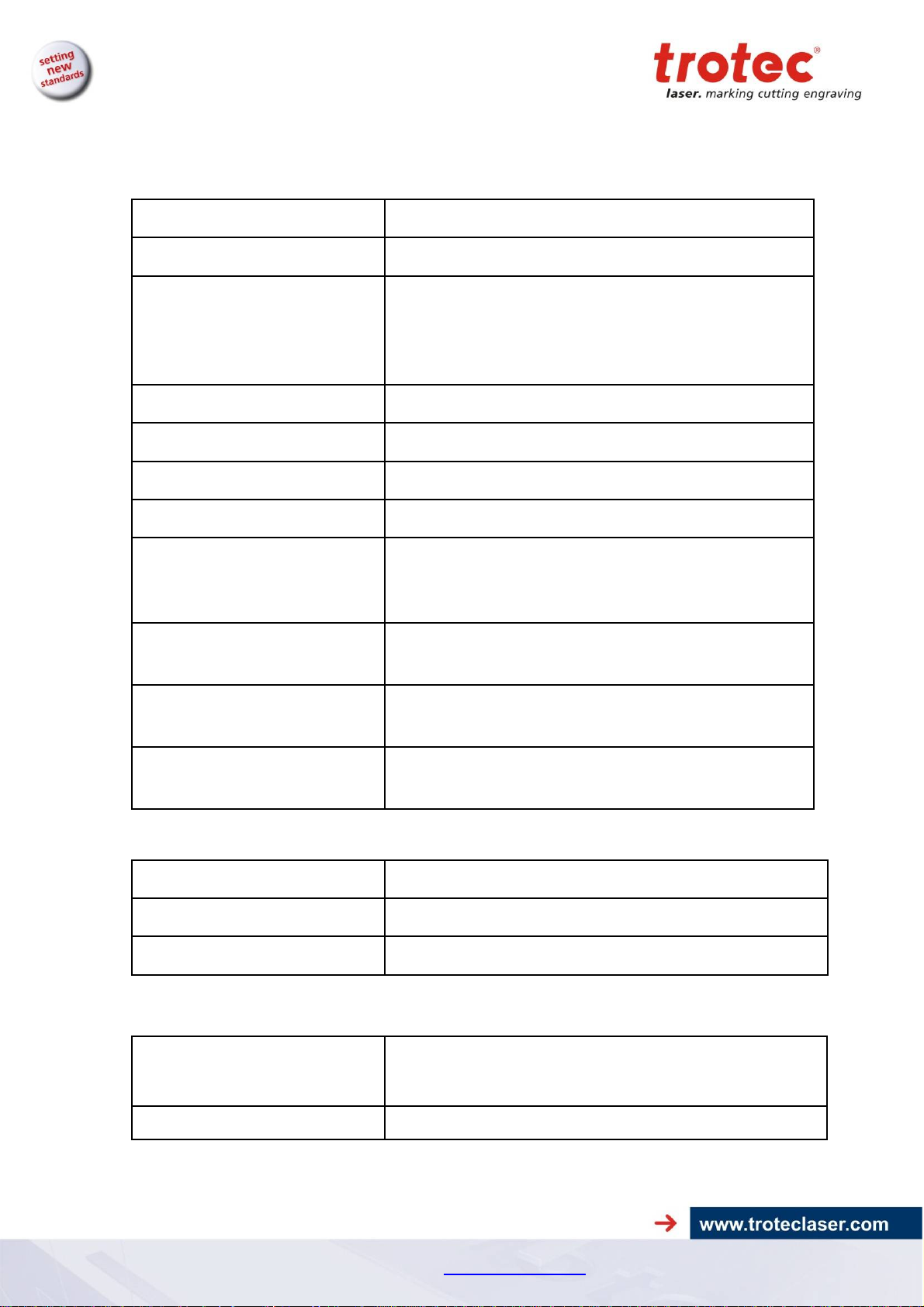
4.3 Dimensions
D
C
B A
Item Description Dimension Units
A Length 2829 (112)
B Width 2197 (87) mm (inch)
C Height, closed
D Height, open
Weight – depends on product model ............... 1200 - 1300kg
1293 (51) mm (inch)
1950 (77) mm (inch)
(2646 - 2867 lbs)
mm (inch)
23/08/2010 Trotec Produktions- und Vertriebs GmbH_Linzer Strasse 156, A-4600 Wels, Austria, Technical Support 10 / 47
tel_+43 (0)7242 239-7000, fax_+43 (0)7242 239-7380, mailto: techsupport@troteclaser.com
SP1500 Operation Manual
µ
Technical Data
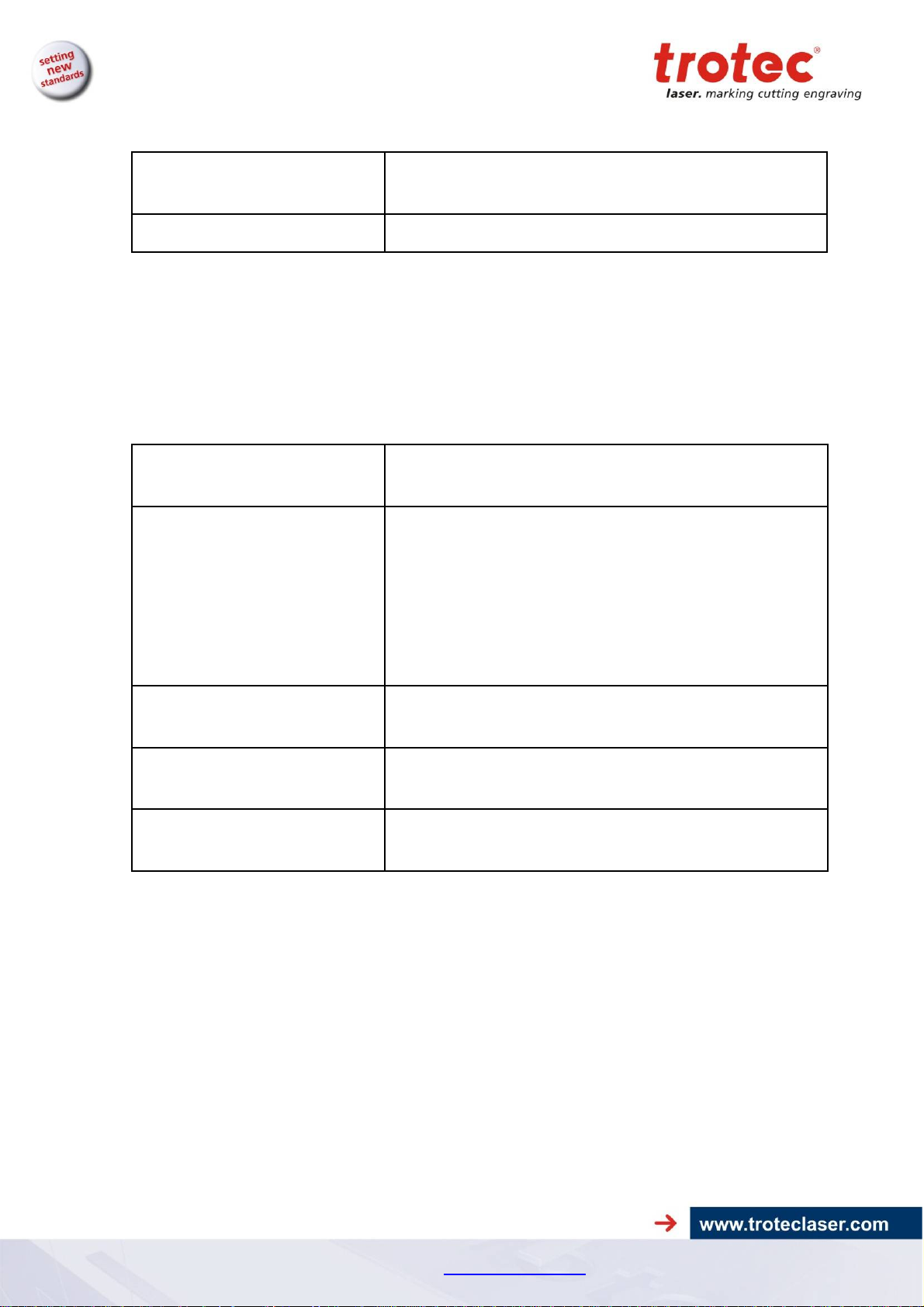
4.4 Mechanical Design
Working area 1500 x 1250 mm (59 x 49 in)
Feed area 1700 x 1600 mm (66 x 62 in)
Max. height of work piece 30 / 53 / 75 mm (1.18 / 2.08 / 2.95 in)
Speed of motion system 165 cm/s (65 in/sec)
Acceleration 9,55 m/s² (375 in/sec²)
Motor Brushless DC servomotor
(3 work table levels)
185 mm (7.28 in) without work table
(flatness cannot be guaranteed without work table)
Encoder Increment measuring system
Lenses
Max. area load of workpiece
table
Precision
Repeatability
4.5 Control System
Laser power Adjustable 0 – 100% (Typically 10-100%)
Hardware Interface USB, RS-232 (RS-232 mandatory for TroCAM and iCut)
Software Interface ASCII, HPGL, Trotec Protocol
2,5“ and 5.0” (Standard), 7.5” (optional)
Lenses and all reflective mirrors are air-flushed and
therefore protected from soiling (preinstalled air pump)
25 kg (55 lbs) over entire working area
±0,1 mm (±0.004 inch) over entire working
(depends on material)
< ±15 µm
(< ±0.00059 inch)
area
4.6 Laser Tubes
Laser tubes
Wavelength 10,6
Sealed off CO2 laser, maintenance free,
Laser power of 60-400W
m
23/08/2010 Trotec Produktions- und Vertriebs GmbH_Linzer Strasse 156, A-4600 Wels, Austria, Technical Support 11 / 47
tel_+43 (0)7242 239-7000, fax_+43 (0)7242 239-7380, mailto: techsupport@troteclaser.com
SP1500 Operation Manual
Technical Data
4.7 Laser Safety
Laser class
Interlock Dual interlock safety system
4.8 Ambient Conditions
Prescribed ambient temperature of +15° to +25°C (+59° to +77°F)
Humidity of 40% to max. 70%, no condensation,
dust-free environment (2nd degree per IEC60947-1)
4.9 Options
CCD-camera Registration marks and compensation system „i-Cut“;
Gas-Kit (for compressed air
respectively process gas)
CDRH Laser Safety; CE tested
Laser class 2
max. working area: 1100 x 700 mm (43 x 27.5 in)
Considered for control of compressed air and process
gas (free of mechanical dust, water and oil) max. flow
rate 150 l/min (40 gpm) with max. 10 bar (145 psi) max.
limit 4 bar on working head push fitting connection with
out diameter) connection on the machine with hose out
diameter of 6mm (0.23 in) resp. standard fitting for
compressed air.
Vacuum table Strong vacuum effect for thin or corrugated materials
(3500 m³/h at 500 Pa)
TroCAM
(refer to TroCAM brochure)
Extraction System lead /followup time
CAD / CAM software for perfect cutting results;
inclusively nesting-function, lead-in/lead-out, tool paths
Lead- and follow-up time fully adjustable
23/08/2010 Trotec Produktions- und Vertriebs GmbH_Linzer Strasse 156, A-4600 Wels, Austria, Technical Support 12 / 47
tel_+43 (0)7242 239-7000, fax_+43 (0)7242 239-7380, mailto: techsupport@troteclaser.com
SP1500 Operation Manual
Technical Data
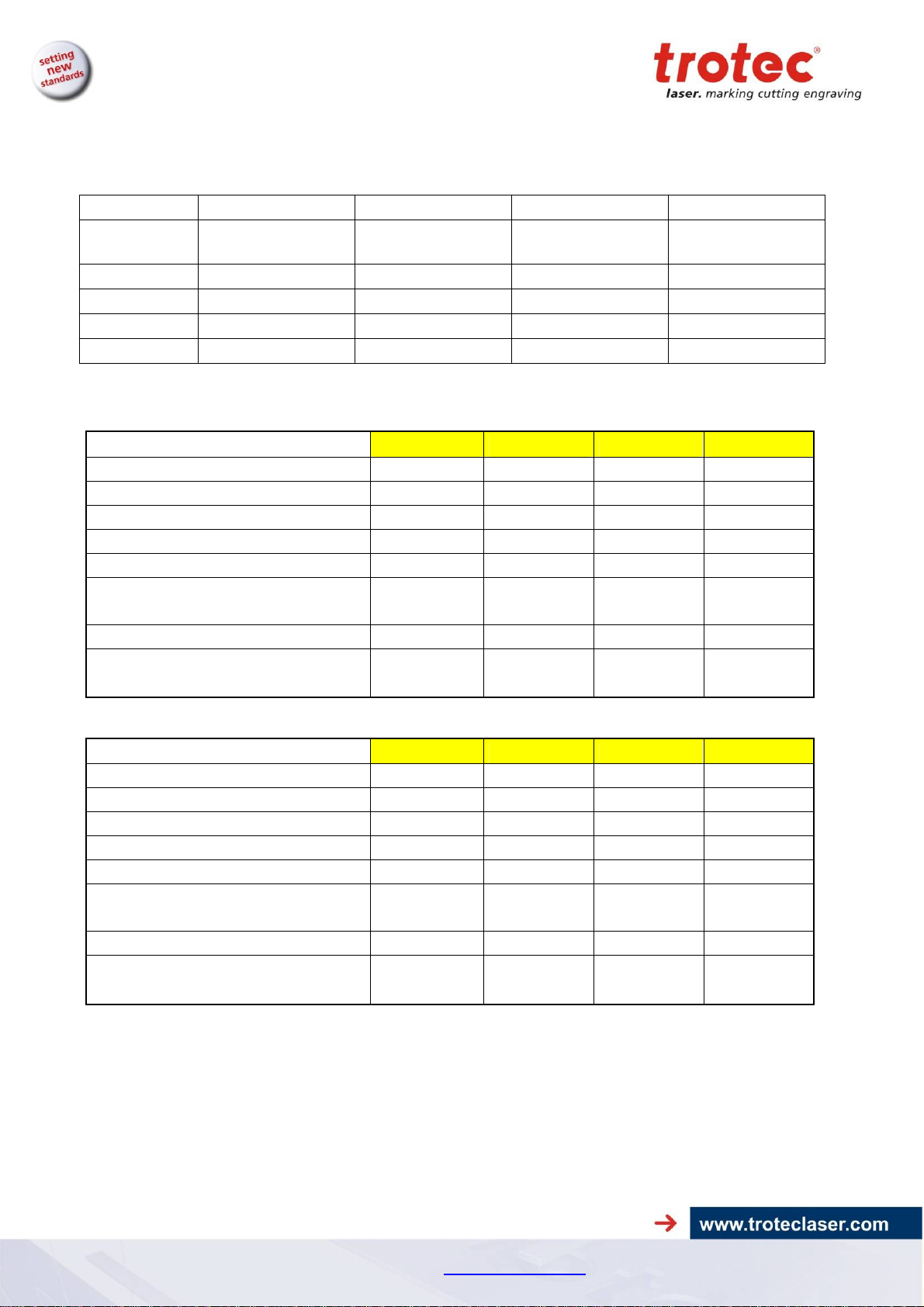
4.10 Electrical Connection
4.10.1 Electrical connection for laser system
Laserpower 60 W 100 W 200 W 400 W
Voltage
Fuse 16 A, slow 20 A, slow 3 x 20 A, slow 3 x 25 A, slow
Frequency 50/60 Hz 50/60 Hz 50/60 Hz 50/60 Hz
Phases L, N, PE L , N, PE L1, L2, L3, N, PE L1,L2,L3,N, PE
Power 2,6 kW 3,5 kW 5,5 kW 9,5 kW
4.10.2 Electrical connection for water cooling (option)
EU
Laserpower
Required refrigerating capacity [W]
Chiller type Chilly 08-S Chilly 25-S Chilly 45-S CWK 90-S
Refrigerating capacity [W]
Rate of flow l/min 7,2 10 16 30
Pressure in bar 2,9 2,7 3,5 3,4
208/230 V,
1 phase
208/230 V,
1 phase
380/400 V,
3 phases
380/400 V,
3 phases
60 W 100 W 200 W 400 W
500 2300 4000 8000
890 2400 5300 9500
Supply voltage
1x230V
50/60Hz
1x230V
50/60Hz
1x230V
50Hz
3x400V
50/60Hz
Power Requirement 900 1800 3000 5900
L1, L2, L3,
Supply voltage L, N, PE L, N, PE L, N, PE
N, PE
US
Laserpower
Required refrigerating capacity [W]
60 W 100 W 200 W 400 W
500 2300 4000 8000
Chiller type Chilly 08-S Chilly 25-S Chilly 35-S CWK 90-S
Refrigerating capacity [W]
890 2400 4500 11000
Rate of flow l/min 8 10 15,2 36
Pressure in bar 3,7 3,5 3,7 4,8
Supply voltage
1x115V
60Hz
1x115V
60Hz
1x230V
50/60Hz
3x400V
50/60Hz
Power Requirement 900 1800 3000 5900
L1, L2, L3,N,
Supply voltage L, N, PE L, N, PE L, N, PE
PE
23/08/2010 Trotec Produktions- und Vertriebs GmbH_Linzer Strasse 156, A-4600 Wels, Austria, Technical Support 13 / 47
tel_+43 (0)7242 239-7000, fax_+43 (0)7242 239-7380, mailto: techsupport@troteclaser.com
SP1500 Operation Manual
Technical Data
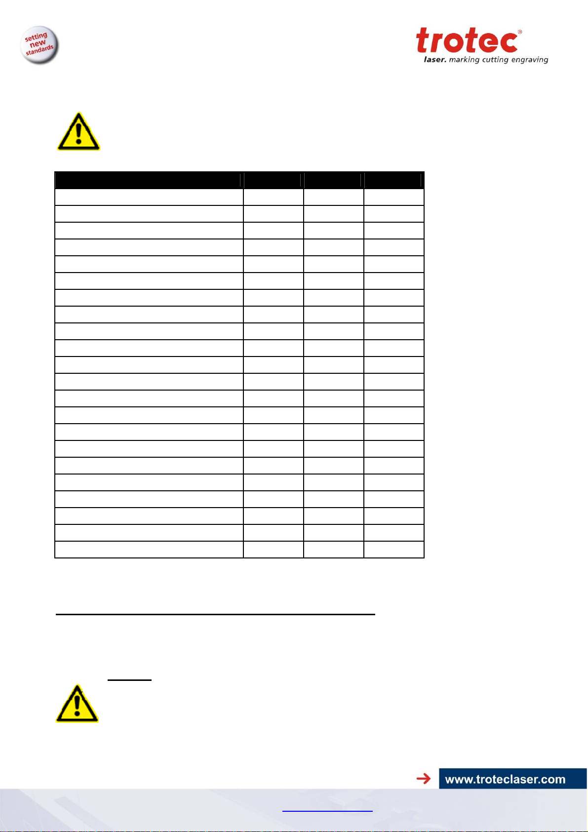
4.11 Materials
Caution when processing conductive materials (carbon fibers,…)! Conductive
dust or particles in the ambient air might damage electrical components and lead
to short circuits.
Bear in mind that those defects are NOT warranted.
Material Engraving Cutting Marking
Acrylic
Painted metal
Delrin
Stainless steel (with Thermark)
Anodized aluminum
Veneer
Handicrafts
Glass
Wood
Gum rubber
Ceramic
Cork
Plastics
Laser rubber
Leather
MDF
Melamine
Micro porous rubber
Paper
Polyester
Stone
PC (Polycarbonate)
Other materials only with written approval by Trotec
The following materials are not recommended for processing:
● ●
● ●
● ●
● ●
●
● ●
● ●
● ●
● ●
● ●
●
● ●
●
● ●
● ●
● ●
● ●
●
● ●
●
●
●
Polyurethane PUR, Polymethylenoxide POM, Polyvinyl chloride PVC, Polyvinyl butyral PVB,
Polytetrafluorethylene PTFE and materials containing epoxy or phenolic resins
Caution:
Trotec assumes no responsibility for any consequences of laser processing in any
application such as medical or pharmaceutical applications.
23/08/2010 Trotec Produktions- und Vertriebs GmbH_Linzer Strasse 156, A-4600 Wels, Austria, Technical Support 14 / 47
tel_+43 (0)7242 239-7000, fax_+43 (0)7242 239-7380, mailto: techsupport@troteclaser.com
SP1500 Operation Manual
Safety
5 Safety
5.1 Safety Instructions
Operating personnel must read and understand the operating instructions, and especially the
“Safety” chapter, before operating the equipment. We recommend that the operator create internal
instructional documentation for equipment safety and operation and to acknowledge receipt of
these instructions/operating manual and participation in training/education in writing (see
documents in the Appendices)
1.1 Intended user group
The machine may only be operated by authorized persons.
Authorities must be clearly defined and observed, so that no unclear competencies result under the
aspect of safety. This applies in particular to work performed on the electrical equipment that may
only be performed by specially trained professionals.
Activity
Intended group of users
Control/operation Trained personnel
Other activities
(e.g. error correction, maintenance)
Specially trained personnel or
hired tradesmen
1.2 Operating instructions / Safety equipment
The safety zone is defined by the operator. Instructions and guidelines must be observed and
followed!
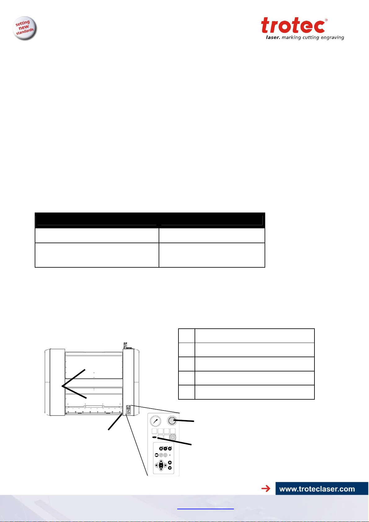
Top view
No. Description
EMERGENCY-OFF pushbutton
4
1
Key switch
2
ON-OFF switch
3
Safety covers
4
3
1
2
23/08/2010 Trotec Produktions- und Vertriebs GmbH_Linzer Strasse 156, A-4600 Wels, Austria, Technical Support 15 / 47
tel_+43 (0)7242 239-7000, fax_+43 (0)7242 239-7380, mailto: techsupport@troteclaser.com
 Loading...