

Page 1
TGH 10 E / TGH 15 E / TGH 30 E
EN
OPERATING MANUAL
GAS HEATER FAN
TRT-BA-TGH10E-TGH15E-TGH30E-TC-002-EN
Page 2
Table of contents
Notes regarding the operating manual................................. 1
Safety .....................................................................................2
You can download the current version of the operating manual
and the EU declaration of conformity via the following link:
Information about the device................................................5
Transport and storage...........................................................6
Assembly and installation.....................................................6
Operation ...............................................................................9
Errors and faults..................................................................11
Maintenance ........................................................................12
Technical annex...................................................................13
Disposal ...............................................................................14
Notes regarding the operating manual
Symbols
Warning of electrical voltage
This symbol indicates dangers to the life and health of
persons due to electrical voltage.
TGH 10 E
http://hub.trotec.com/?id=40945
TGH 15 E
http://hub.trotec.com/?id=40946
TGH 30 E
http://hub.trotec.com/?id=40947
Warning of hot surface
This symbol indicates dangers to the life and health of
persons due to hot surface.
Warning
This signal word indicates a hazard with an average
risk level which, if not avoided, can result in serious
injury or death.
Caution
This signal word indicates a hazard with a low risk
level which, if not avoided, can result in minor or
moderate injury.
Notice
This signal word indicates important information
(e.g. material damage), but does not indicate hazards.
Info
Information marked with this symbol helps you to carry
out your tasks quickly and safely.
Follow the manual
Information marked with this symbol indicates that the
operating manual must be observed.
1 EN
Operating manual – gas heater fan TGH 10 E / TGH 15 E / TGH 30 E
Page 3

Safety
Read this manual carefully before starting or using the
device. Always store the manual in the immediate vicinity
of the device or its site of use!
Warning
Read all safety warnings and all instructions.
Failure to follow the warnings and instructions may
result in electric shock, fire and/ or serious injury.
Save all warnings and instructions for future
reference.
This appliance can be used by children aged from
8 years and above and persons with reduced physical,
sensory or mental capabilities or lack of experience
and knowledge if they have been given supervision or
instruction concerning use of the appliance in a safe
way and understand the hazards involved.
Children shall not play with the appliance. Cleaning and
user maintenance shall not be made by children
without supervision.
• Do not use the device in potentially explosive rooms.
• Do not use the device in aggressive atmosphere.
• Set the device up in an upright and stable position.
• Let the device dry out after a wet clean. Do not operate it
when wet.
• Do not use the device with wet or damp hands.
• Do not expose the device to directly squirting water.
• Never insert any objects or limbs into the device.
• Do not cover or transport the device during operation.
• Do not sit on the device.
• This appliance is not a toy! Keep away from children and
animals. Do not leave the device unattended during
operation.
• Check accessories and connection parts for possible
damage prior to every use of the device. Do not use any
defective devices or device parts.
• Ensure that all electric cables outside of the device are
protected from damage (e.g. caused by animals). Never
use the device if electric cables or the power connection
are damaged!
• The electrical connection must correspond to the
specifications in chapter Technical data.
• Insert the mains plug into a properly secured mains
socket.
• Observe the device's power input, cable length and
intended use when selecting extensions to the power
cable. Completely unroll extension cables. Avoid electrical
overload.
• Before carrying out maintenance, care or repair work on
the device, remove the mains plug from the mains socket.
Hold onto the mains plug while doing so.
• Switch the device off and disconnect the power cable from
the mains socket when the device is not in use.
• Do not under any circumstances use the device if you
detect damages on the mains plug or power cable.
If the supply cord is damaged, it must be replaced by the
manufacturer, his service agent or similarly qualified
persons in order to avoid a hazard.
Defective power cables pose a serious health risk.
• Observe the storage and operating conditions (see chapter
Technical data).
• Ensure a minimum distance of 3m to combustible
substances. Do not use the device in rooms where fuel,
solvents, varnishes or other easily inflammable vapours
are stored.
• Ensure that the air inlet and outlet are not obstructed.
• Do not place the device on combustible ground.
• Allow the device to cool down before transport and/ or
maintenance work.
• Protect the device from moisture, e.g. rain.
• Protect the gas cylinder from sub-zero temperatures also
known as frost.
• Carefully inspect all connection points for tightness.
Attention! Leak testing by way of naked flame is strictly
forbidden!
• The exchange of gas cylinders is only permitted in an
environment devoid of ignition sources.
• In case of gas leakage (smell) immediately close the gas
cylinder's main valve and keep the device at a distance to
any fire source.
• Never turn the gas cylinder over, even though it may seem
empty! This could cause an obstruction in the hose with
the remains from the gas cylinder and so lead to a fire
hazard and immediate damage of the device.
• Do not twist the gas hose.
• Do not dismantle the protective grid and/ or other device
components.
• Do not position the gas cylinder in front of the device. Risk
of fire and explosion!
• Only use the original gas hose and original spare parts.
• Keep fire extinguisher and first-aid kit on hand.
• Bear in mind, that you may have to meet different national
requirements. Observe the local regulations regarding
admissible deviations. In Germany consult the Technical
Rules for Liquid Gas (TRF2012) as well as the relevant
accident prevention regulations (VBG and ZH1/455).
EN 2
Operating manual – gas heater fan TGH 10 E / TGH 15 E / TGH 30 E
Page 4

Intended use
Only use the device TGH 10 E / TGH 15 E / TGH 30 E for
generating hot air in well-ventilated interior spaces or in roofed
outdoor areas protected from weather effects.
Do not use the device in windowless rooms below ground level.
Only use the device in rooms corresponding to the minimum
dimensions specified in the technical data.
• The device is suited for heating large rooms such as tents,
warehouses, workshops, construction sites, greenhouses
or agricultural halls.
• The device may only be used in rooms with sufficient fresh
air supply and exhaust discharge. The ventilation shaft
must have a cross-section of at least 25cm2 per kW
nominal heat output. It is determined based on the calorific
value. The minimum ventilation cross-section amounts to
250cm2.
• It is intended to be used without frequent site changes.
• The device must only be fuelled by propane.
The device may only be used in certain countries of destination
whilst adhering to the technical data.
Improper use
• The device MUST NOT BE USED FOR HEATING
HABITABLE ROOMS IN RESIDENTIAL BUILDINGS; FOR
THE USE IN PUBLIC BUILDINGS: OBSERVE NATIONAL
REGULATIONS.
• The device must not be positioned or operated in areas
with a high risk of fires or in potentially explosive
atmospheres.
• Do not place the device on wet or flooded ground.
• Do not place any objects, e.g. clothing, on the device.
• Do not use the device out of doors, unless under a roof.
• The device must not be operated in rooms with an
insufficient combustion air supply.
• The device must not be operated in rooms below ground
level (souterrain or the like).
• Any unauthorised modifications, alterations or structural
changes to the device are forbidden.
• Any operation other than as described in this manual is
prohibited. Non-observance renders all claims for liability
and guarantee null and void.
Personnel qualifications
People who use this device must:
• have read and understood the operating manual, especially
the Safety chapter.
Symbols on the device
Symbols Meaning
This symbol located on the device indicates that it
is prohibited to place objects (such as towels,
clothes etc.) above or directly in front of the
device.
In order to avoid overheating and fire hazards, the
heater must not be covered.
Residual risks
Warning of electrical voltage
Work on the electrical components must only be
carried out by an authorised specialist company!
Warning of electrical voltage
Before any work on the device, remove the mains plug
from the mains socket!
Hold onto the mains plug while pulling the power cable
out of the mains socket.
Warning of explosive substances
Explosion hazard in case of leaking gas connections.
If you smell gas, immediately close the valve at the gas
cylinder and exit the room/ area. Also notify the fire
brigade.
Warning of hot surface
Some parts of this product can become very hot and
cause burns. Particular attention has to be given where
children and vulnerable people are present!
Warning
Improper handling entails a risk of burning and electric
shock.
Only use the device as intended!
Warning
Dangers can occur at the device when it is used by
untrained people in an unprofessional or improper way!
Observe the personnel qualifications!
Warning
The device is not a toy and does not belong in the
hands of children.
Warning
Risk of suffocation!
Do not leave the packaging lying around. Children may
use it as a dangerous toy.
Warning
Improper installation entails a risk of fire.
Do not place the device on combustible ground.
Do not place the device on high-pile carpets.
3 EN
Operating manual – gas heater fan TGH 10 E / TGH 15 E / TGH 30 E
Page 5
Warning
In order to avoid overheating and fire hazards, the
heater must not be covered.
Warning
Inhaling propane may cause damages to health. Ensure
the tightness of all connections. Only use the device in
well-ventilated spaces or out of doors.
Warning
Oxygen is consumed during the operation of the
device. In smaller rooms this would result in an oxygen
deficiency. Only use the device in well-ventilated
spaces or out of doors.
Warning
There is a danger of suffocation and poisoning due to
the carbon monoxide formed during unclean
combustion and the lack of fresh air supply/
ventilation.
Do not use the device in windowless basements or
other spaces below ground level.
Only use the device in well-ventilated spaces or out of
doors.
Do not leave the device running unattended.
Behaviour when having detected the smell of gas
If you suspect a gas leak, e.g. you smell gas, make sure to
observe the instructions below:
• Do not actuate any electrical switches! Do not switch on
the light!
• Do not use a phone – corded, wireless or mobile – in the
danger area.
• Do not use naked flames or other open sources of ignition,
e.g. a lighter or match. Do not smoke!
• Immediately close the gas cylinder's main valve by turning
the gas cock clockwise.
• Open all doors and windows to ensure a sufficient fresh air
supply.
Behaviour in the event of an emergency
1. Turn the gas off at the main valve.
2. Quickly leave the danger area. Remove other persons from
the danger area.
3. Notify the fire brigade.
Overheating protection
The device is provided with a safety thermostat which is
activated by overheating of the device (when exceeding the
operating temperature).
As a result, the gas supply will be interrupted. The fan keeps
running.
The safety thermostat resets automatically when cooled down
sufficiently, but the device will have to be restarted. Investigate
the cause of overheating before switching the device back on.
Flame failure protection
The device comes equipped with a temperature sensor which
ensures that the temperature stays above 430°C. As soon as
the device falls below this temperature the valve closes and
interrupts the gas flow. This prevents an involuntary emission of
unburnt gas. So long as the gas flame heats the sensor, the gas
outlet is open. As soon as the flame dies, the gas flow will be
interrupted.
EN 4
Operating manual – gas heater fan TGH 10 E / TGH 15 E / TGH 30 E
Page 6
Information about the device
1
2
3
7
6
5
4
1
2
3
7
6
5
4
8
9
Device description
The device TGH 10 E / TGH 15 E / TGH 30 E was developed for
the purpose of generating hot air and may only be used in
roofed over outdoor areas or in well-ventilated interior spaces
whilst adhering to the technical data.
The device generates heat by burning propane. The fan sucks in
the ambient air and feeds it through the combustion area. In this
area the supplied gas is burnt under controlled conditions and
the warm air discharged through the air outlet.
The device comes equipped with a piezo igniter for lighting the
torch.
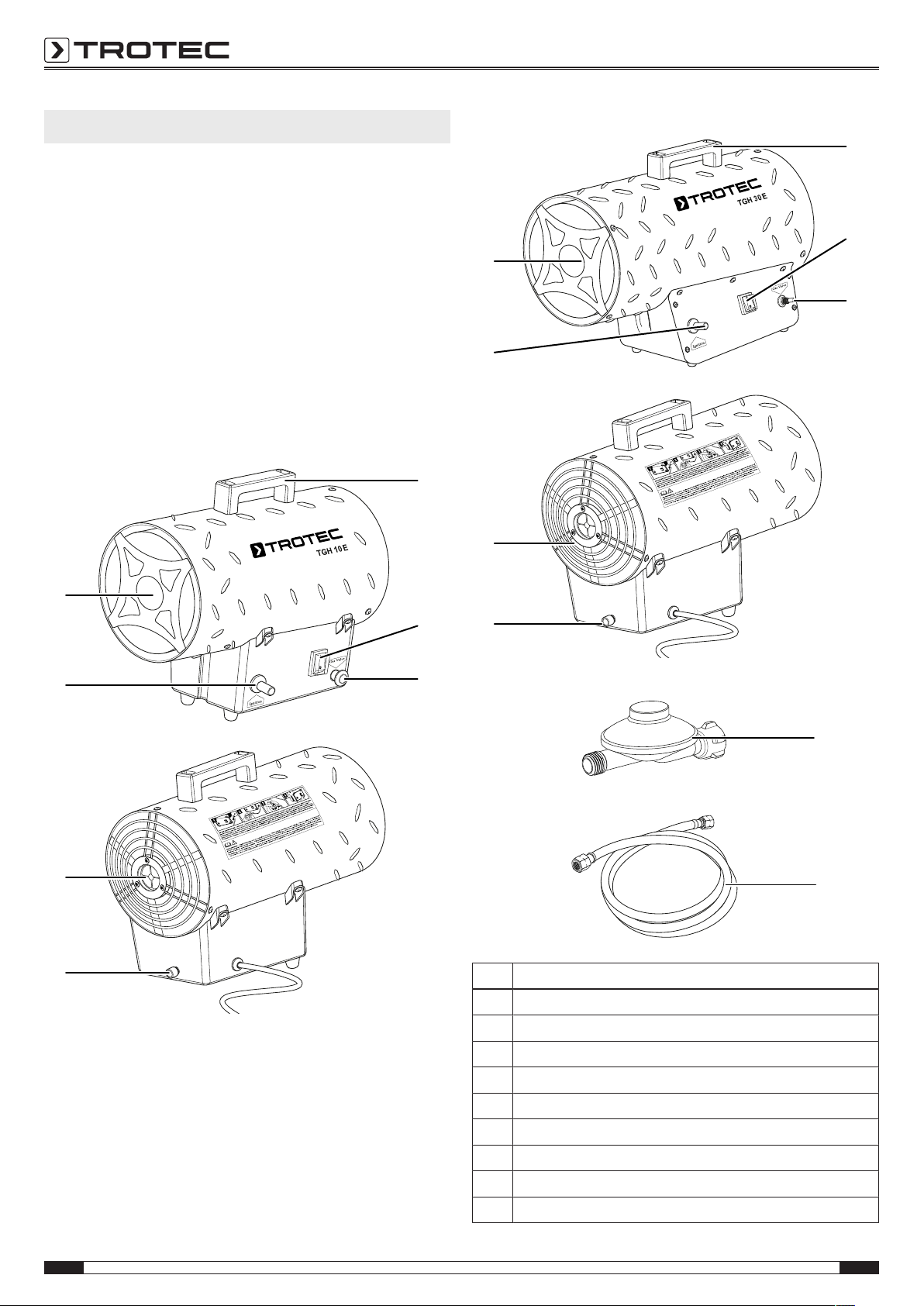
Device depiction
TGH 10 E / TGH 15 E
TGH 30 E
Accessories for TGH10E/ TGH15E/ TGH30E
No. Designation
1 Transport handle
2 ON/OFF switch
3 Gas valve push button
4 Gas hose connection
5 Air inlet
6 Ignition button (piezo igniter)
7 Air outlet
8 Pressure reducer
9 Gas hose
5 EN
Operating manual – gas heater fan TGH 10 E / TGH 15 E / TGH 30 E
Page 7

Transport and storage
Assembly and installation
Notice
If you store or transport the device improperly, the
device may be damaged.
Note the information regarding transport and storage of
the device.
Transport
To make the device easier to transport, it is fitted with a
transport handle.
Before transporting the device, observe the following:
• Switch off the device.
• Hold onto the mains plug while pulling the power cable out
of the mains socket.
• Do not use the power cable to drag the device.
• Do not use the gas hose to drag the device.
• Allow the device to cool down sufficiently.
• Close the valve at the gas cylinder and disconnect the gas
hose.
• Transport gas cylinder and device separately.
After transporting the device, observe the following:
• Please observe the information for device set-up:
• Re-connect the gas hose and carry out a leak test (see
chapter Assembly and installation).
Storage
Before storing the device, proceed as follows:
• Close the valve at the gas cylinder and disconnect the gas
hose.
• Allow the device to cool down sufficiently.
When the device is not being used, observe the following
storage conditions:
• dry
• under roof
• in an upright position where it is protected from dust and
direct sunlight
• with a cover to protect it from invasive dust, if necessary
• Place no further devices or objects on top of the device to
prevent it from being damaged.
• Store gas cylinder and device separately.
• The storage temperature is the same as the range given
for the operating temperature in the technical data.
Scope of delivery
• 1x Device
• 1 x Gas hose, class 2, 6.3mm, 10bar, length: 1.5m
• 1 x Pressure reducer 700mbar, suitable for gas cylinders
from Germany, Austria, Belgium, the Netherlands and
Poland
• 1 x Transport handle
• 2 x Screw
• 2 x Washer
• 1x Manual
Unpacking the device
1. Open the cardboard box and take the device out.
2. Completely remove the packaging.
3. Fully unwind the power cable. Make sure that the power
cable is not damaged and that you do not damage it during
unwinding.
Assembly
Use tools suitable for the intended task.
Mounting the transport handle
Prior to initial start-up, the transport handle must be attached to
the device.
The procedure is identical for the devices TGH 10 E / TGH 15 E /
TGH 30 E.
To do so, please proceed as follows:
1. Loosen the two screws and the two washers from the top
of the housing.
EN 6
Operating manual – gas heater fan TGH 10 E / TGH 15 E / TGH 30 E
Page 8

2. Use the screws and washers to mount the transport
handle.
Connecting the gas cylinder
Info
Use tools suitable for the intended task.
Make sure not to damage the valve seal.
Damage could lead to a point of leakage at the gas
connection. And leaks connote an explosion hazard!
1. First connect the pressure reducer to the gas cylinder. To
do so, screw the union nut of the pressure reducer in a
counter-clockwise motion onto the thread of the gas
cylinder.
2. Connect one end of the gas hose to the pressure reducer.
For this purpose, screw the union nut of the gas hose onto
the external thread of the pressure reducer by turning it
counter-clockwise. Use an open-end wrench of size SW17
or SW19 to do so.
Please note that the gas hose must not be kinked or
twisted.
Info
The pressure reducer included in the scope of delivery
is only suitable for gas cylinders from the following
countries of destination: Germany, Austria, Belgium,
the Netherlands and Poland.
For all other countries of destination, a suitable
pressure reducer must be purchased separately.
Info
Once assembled, do not turn the pressure reducer!
Rotating the pressure reducer after completed
assembly could cause damage to the valve seal at the
gas cylinder.
Damage could lead to a point of leakage at the gas
connection. And leaks connote an explosion hazard!
If you transported the gas cylinder, let it rest for about 1hour in
an upright position before connecting it. That way, the particles
that are harmful to the environment have time to settle at the
bottom.
3. Remove the protective cap from the hose connection at the
device.
7 EN
Operating manual – gas heater fan TGH 10 E / TGH 15 E / TGH 30 E
Page 9

4. Connect the other end of the gas hose to the hose
2 m
3,5 m
2 m
2 m
2,5 m
connection of the device. For this purpose, screw the union
nut of the gas hose onto the gas connection of the device
by turning it counter-clockwise. Use an open-end wrench
of size SW17 or SW19 to do so.
Start-up
Info
Odours might arise upon initial start-up or after a
longer period of non-use. There might be a passing
smell of burnt material.
A smell of gas however indicates a leak at the gas
connection that must be remedied immediately.
Otherwise there is an explosion hazard!
A number of spatial and technical conditions have to be
considered for the selection of the device's installation site.
Non-observance may impair the proper functioning of the device
or the accessories or can entail risks of personal injury and
property damage.
Only use the device in rooms corresponding to the minimum
dimensions specified in the Technical data chapter. When
positioning the device, observe the minimum distance from
walls or other objects as described in the Technical data
chapter.
• For outdoor application, the device may only be used when
located under a roof.
• The device is to be set up in a stable position on
incombustible ground.
• The room where the device is positioned must be
sufficiently ventilated. The ventilation shaft must have a
cross-section of at least 25cm2 per kW nominal heat
output. It is determined based on the calorific value.
• Do not use the device in windowless basements or other
spaces below ground level.
• The inlet and outlet openings must not be covered.
• Never direct the air outlet towards the gas cylinder.
• There must be no walls or large objects near the device.
• There must be a sufficient number of fire extinguishers
available.
• Before restarting the device, check the condition of the
power cable. If there are doubts as to the sound condition,
contact the customer service.
• Do not create tripping hazards when laying the power
cable or other electric cables, especially when positioning
the device in the middle of the room. Use cable bridges.
• Make sure that extension cables are completely unrolled.
• Make sure that the device cannot come into contact with
moisture or water.
EN 8
Operating manual – gas heater fan TGH 10 E / TGH 15 E / TGH 30 E
Page 10

Leak testing
2
TGH 10 E / TGH 15 E
Notice
A leak test can only be performed when the device is
cold.
Prior to initial start-up and before every new start-up operation
the gas connection needs to be checked for tightness in the first
instance. Use a spray bottled filled with soap water (water/soap
mixing ratio 3:1, approx. 50ml) or a suitable leak detector
spray.
1. Open the valve at the gas cylinder.
2. Spray some of the soap water onto the connection points.
ð A formation of bubbles indicates leakage.
Operation
Info
Ensure the tightness of all connections.
Make sure that the fan operates properly.
The device must not be taken into operation unless
these conditions are met!
Switching the device on
Once you have completely installed the device as described in
the Start-up chapter, you can switch it on.
Notice
The fan must be running during operation. An idle fan
during operation might lead to overheating.
1. Open the valve at the gas cylinder.
3. Turn the gas off again using the valve.
4. Use a clean cloth to wipe the connection faces dry.
5. (Re-)Tighten any leaking connections.
6. Repeat the tightness test until no more bubbles appear and
the connections are sealed tightly.
7. If the leak cannot be eliminated in this manner, gas hose
and pressure reducer need to be replaced.
Info
After having assembled a new gas hose and pressure
reducer again check the gas connection for tightness.
This is the only way to reliably rule out leakage at the
gas connection.
Connecting the power cable
• Plug the mains plug into a sufficiently fused mains socket.
• Make sure that the power cable is guided along the back
of the device. Never guide the power cable along the front
of the device!
2. Switch on the fan by setting the on/off switch(2) to
position I.
9 EN
Operating manual – gas heater fan TGH 10 E / TGH 15 E / TGH 30 E
Page 11

2
TGH 30 E
ð The on/off switch(2) will be illuminated in red.
3
6
TGH 10 E / TGH 15 E
3
6
TGH 30 E
10sec
TGH 10 E / TGH 15 E
10sec
TGH 30 E
3. Leave the fan running for approx. 30s.
4. Press and hold the push button for the gas valve(3) while
actuating the ignition button(6).
6. Hold onto the gas valve push button(3) for roughly another
10s after the ignition has been successful.
5. It may be necessary to actuate the ignition button(6)
repeatedly before the gas catches fire.
EN 10
7. Then let go of the button(3).
ð The combustion itself is an automatically controlled
process.
Info
Excessive temperature trips the overheating protection
which in turn interrupts the gas supply.
If the flame dies, the flame failure protection kicks in
which also interrupts the gas supply.
If the device switches off upon releasing the gas valve push
button(3), please proceed as follows:
1. Keep the fan running for approx. 1minute to let the gas
escape completely.
Operating manual – gas heater fan TGH 10 E / TGH 15 E / TGH 30 E
2. Repeat the ignition process as described above.
Page 12

Info
If you experience difficulties in lighting the torch, check
the air current.
Make sure that the fan is not blocked.
Make sure that air inlet and outlet are not obstructed.
If you use the device for an extended period of time, excessive
evaporation may cause a fine film to settle on the gas cylinder.
Info
Never direct the air outlet towards the gas cylinder!
Do not position the gas cylinder in front of the device!
Risk of fire and explosion!
1. Replace the gas cylinder with a new one or use a larger
gas cylinder.
Using the device as fan
You may also use the device as a fan for air circulation.
1. Make sure that the device is not connected to the gas
supply. The gas connection is rendered redundant during
the ventilation operation.
2. Remove the gas hose as appropriate.
3. Switch on the fan by setting the on/off switch(2) to
position I.
ð The device now operates as fan.
Shutdown
1. Tightly close the valve at the gas cylinder.
Errors and faults
Warning of electrical voltage
Tasks which require the housing to be opened
must only be carried out by authorised specialist
companies or by Trotec.
The device has been checked for proper functioning several
times during production. If malfunctions occur nonetheless,
check the device according to the following list.
The fan does not start:
• Check whether the device is switched on. The on/off
switch(2) should be set to I.
• Check the power connection.
• Check the power cable and mains plug for damages.
• Check the on-site fusing.
• Check whether the overheating protection has tripped, see
chapter Safety.
• The fan motor might be defective. Have a defective fan
motor replaced by a specialist electrical company.
• There might be a fault in the circuitry. Have the electrical
system checked by a specialist electrical company.
The fan is running, but the gas fails to ignite:
• Check whether the device is switched on.
• Check whether the connection line is properly connected.
• Make sure that the valve at the gas cylinder is open.
• Perhaps the gas cylinder is empty and needs to be
replaced.
• The ignition electrode may be dirty or positioned
incorrectly. Have a specialist electrical company check the
ignition electrode.
The fan is running, the gas is ignited, but the flame dies
after a little while:
• Check whether the gas hose is properly connected.
• Perhaps the gas cylinder is empty and needs to be
ð The flame goes out after a little while.
2. Keep the fan running for 3minutes before switching the
device off.
3. Set the on/off switch(2) to position 0.
replaced.
• There might be a defect at the sensors or another part of
the circuitry. Have the electrical system checked by a
specialist electrical company.
4. Hold onto the mains plug while pulling the power cable out
of the mains socket.
5. Allow the device to cool down completely.
6. Disconnect the pressure reducer from the gas cylinder.
7. Loosen the hose connections at device and pressure
reducer.
8. Clean the device according to the Maintenance chapter.
9. Store the device according to the Storage chapter.
11 EN
Operating manual – gas heater fan TGH 10 E / TGH 15 E / TGH 30 E
Page 13

The flame goes out during operation:
• Check whether the overheating protection has tripped, see
chapter Safety.
• Check whether the flame failure protection has tripped,
see chapter Safety.
• Perhaps the gas cylinder is empty and needs to be
replaced.
• The pressure reducer might be defective causing an
excessive gas supply. Replace the pressure reducer.
• Insufficient gas supply due to icing on the gas cylinder.
Perhaps use a gas cylinder with a higher output rate, see
gas consumption in the Technical data chapter.
• The supplied amount of combustion air might be
insufficient. Check the air inlet for obstructions and
whether the fan operates properly. If there is a problem
with the fan, have it checked by a specialist electrical
company.
Maintenance
Have a specialist electrical company check the device for proper
functioning once a year. The same shall apply, when taking the
device back into operation after having stored it for a longer
period of time.
Activities required before starting maintenance
Warning of electrical voltage
Do not touch the mains plug with wet or damp hands.
• Switch off the device.
• Hold onto the mains plug while pulling the power cable out
of the mains socket.
Warning of electrical voltage
Tasks which require the housing to be opened
must only be carried out by authorised specialist
companies or by Trotec.
The flame is too high:
• Too much gas is emitted. The pressure reducer might be
defective and needs to be replaced.
The device is loud or vibrates:
• Check whether the device is set up in a stable and upright
position.
Notice
Wait for at least 3 minutes after maintenance and
repair work. Only then switch the device back on.
Your device still does not operate correctly after these
checks?
Please contact the customer service. If necessary, bring the
device to an authorized specialist electrical company or to
Trotec for repair.
Cleaning the housing
Clean the housing with a soft, damp and lint-free cloth. Ensure
that no moisture enters the housing. Protect electrical
components from moisture. Do not use any aggressive cleaning
agents such as cleaning sprays, solvents, alcohol-based or
abrasive cleaners to dampen the cloth.
Wipe the housing dry after cleaning.
Cleaning the inside of the device
If required, blow the device interior out with compressed air to
remove slight contamination such as dust deposits.
Leak testing
Tightness tests ought to be performed at regular intervals and
after extended idle times (see Start-up chapter).
Provisions to be made in case the device has to be left unattended without safeguards
If the device has to be left unattended without safeguards,
protect the device against unauthorized use, e.g. by fencing in
the gas cylinders.
Leave the premises and repair to open space.
Warn others.
EN 12
Operating manual – gas heater fan TGH 10 E / TGH 15 E / TGH 30 E
Page 14

Technical annex
Technical data
Parameter Value
Model TGH 10 E TGH 15 E TGH 30 E
Heating capacity 10 kW 15 kW 30 kW
Gas consumption 730 g/h 1,090 g/h 2,180 g/h
Type of gas Propane Propane Propane
Operating pressure 0.7 bar 0.7 bar 0.7 bar
Gas cylinder capacity ≤ 33kg ≤ 33kg ≤ 33kg
Air flow rate 320 m³/h 320 m³/h 650 m³/h
Air outlet temperature
84.5°C 79.5°C 75.6°C
(1.5m distance)
Operating range -15°C to +30°C -15°C to +30°C -15°C to +30°C
Sound pressure level
48 dB(A) 48 dB(A) 65 dB(A)
(1m distance)
Mains connection 220-240V/ 50Hz 220-240V/ 50Hz 220-240V/ 50Hz
Max. power input 10 kW 15 kW 30 kW
Nominal current consumption 0.23A 0.23A 0.29 A
Protection class I I I
Plug type CEE 7/4 CEE 7/4 CEE 7/4
Cable length 1.6m 1.6m 1.6m
Dimensions
380 x 190 x 305 (mm) 380 x 190 x 305 (mm) 475 x 225 x 360 (mm)
(depth x width x height)
Weight 4 kg 4 kg 6 kg
Overheating protection 95 °C 80 °C 75 °C
Ignition head Piezo igniter Piezo igniter Piezo igniter
Flame failure protection x x x
Minimum distance to walls and
other objects
top:
rear:
sides:
front:
2 m
2.5 m
2 m
3.5 m
2 m
2.5 m
2 m
3.5 m
2 m
2.5 m
2 m
3.5 m
Min. room size 100 m³ 150 m³ 300 m³
Min. ventilation cross-section 250 cm³ 375 cm³ 750 cm³
13 EN
Operating manual – gas heater fan TGH 10 E / TGH 15 E / TGH 30 E
Page 15

Parameter Value
Pressure reducer 700 mbar
700 mbar
700 mbar
The pressure reducer included
in the scope of delivery is only
suitable for gas cylinders from
the following countries of
destination: Germany, Austria,
Belgium, the Netherlands and
Poland.
Country of destination Austria, Belgium, Switzerland,
Czech Republic, Germany,
Denmark, Finland, Greece,
Hungary, Ireland, Italy,
Lithuania, Latvia, the
Netherlands, Norway, Poland,
Slovakia
The pressure reducer
included in the scope of
delivery is only suitable for
gas cylinders from the
following countries of
destination: Germany,
Austria, Belgium, the
Netherlands and Poland.
Austria, Belgium,
Switzerland, Czech
Republic, Germany,
Denmark, Finland, Greece,
Hungary, Ireland, Italy,
Lithuania, Latvia, the
Netherlands, Norway,
Poland, Slovakia
Equipment category I3B/P I3B/P I3B/P
Disposal
The icon with the crossed-out waste bin on waste
electrical or electronic equipment stipulates that this equipment
must not be disposed of with the household waste at the end of
its life. You will find collection points for free return of waste
electrical and electronic equipment in your vicinity. The
addresses can be obtained from your municipality or local
administration. For further return options provided by us please
refer to our website www.trotec24.com.
The separate collection of waste electrical and electronic
equipment aims to enable the re-use, recycling and other forms
of recovery of waste equipment as well as to prevent negative
effects for the environment and human health caused by the
disposal of hazardous substances potentially contained in the
equipment.
EN 14
Operating manual – gas heater fan TGH 10 E / TGH 15 E / TGH 30 E
Page 16

Page 17

Trotec GmbH & Co. KG
Grebbener Str. 7
D-52525 Heinsberg
+49 2452 962-400
+49 2452 962-200
info@trotec.com
www.trotec.com
 Loading...