

Page 1

TAC 1500 / TAC 3000
EN
ORIGINAL INSTRUCTIONS
AIR CLEANER
TRT-BA-TAC1500/TAC3000-TC2018-55-006-EN
Page 2

Table of contents
Notes regarding the instructions ..........................................2
Safety .....................................................................................2
You can download the current version of the instructions and
the EUdeclaration of conformity via the following link:
Information about the device................................................4
Transport and storage...........................................................5
Assembly and start-up..........................................................5
Operation .............................................................................11
Available accessories..........................................................11
Errors and faults..................................................................11
Maintenance ........................................................................12
Technical annex...................................................................13
Disposal ...............................................................................15
Declaration of conformity ...................................................15
Notes regarding the instructions
Symbols
Warning of electrical voltage
This symbol indicates dangers to the life and health of
persons due to electrical voltage.
Warning
This signal word indicates a hazard with an average
risk level which, if not avoided, can result in serious
injury or death.
Caution
This signal word indicates a hazard with a low risk
level which, if not avoided, can result in minor or
moderate injury.
Note
This signal word indicates important information
(e.g. material damage), but does not indicate hazards.
Info
Information marked with this symbol helps you to carry
out your tasks quickly and safely.
Follow the manual
Information marked with this symbol indicates that the
instructions must be observed.
TAC 1500
https://hub.trotec.com/?id=42768
TAC 3000
https://hub.trotec.com/?id=42769
Safety
Read this manual carefully before starting or using the
device. Always store the manual in the immediate vicinity
of the device or its site of use!
Warning
Read all safety warnings and all instructions.
Failure to follow the warnings and instructions may
result in electric shock, fire and/ or serious injury.
Save all warnings and instructions for future
reference.
This appliance can be used by children aged from
8years and above and persons with reduced physical,
sensory or mental capabilities or lack of experience
and knowledge if they have been given supervision or
instruction concerning use of the appliance in a safe
way and understand the hazards involved.
Children shall not play with the appliance. Cleaning and
user maintenance shall not be made by children
without supervision.
• Do not use the device in potentially explosive rooms.
• Do not use the device in aggressive atmosphere.
• Set the device up in an upright and stable position.
• Let the device dry out after a wet clean. Do not operate it
when wet.
• Do not use the device with wet or damp hands.
• Do not expose the device to directly squirting water.
• Never insert any objects or limbs into the device.
• Do not cover or transport the device during operation.
• Do not sit on the device.
2 EN
air cleaner TAC 1500 / TAC 3000
Page 3

• This appliance is not a toy! Keep away from children and
animals. Do not leave the device unattended during
operation.
• Check accessories and connection parts for possible
damage prior to every use of the device. Do not use any
defective devices or device parts.
• Ensure that all electric cables outside of the device are
protected from damage (e.g. caused by animals). Never
use the device if electric cables or the power connection
are damaged!
• The electrical connection must correspond to the
specifications in chapter Technical data.
• Insert the mains plug into a properly secured mains
socket.
• Observe the technical data when selecting extensions to
the power cable. Completely unroll the extension cable.
Avoid electrical overload.
• Before carrying out maintenance, care or repair work on
the device, remove the mains plug from the mains socket.
Hold onto the mains plug while doing so.
• Switch the device off and disconnect the power cable from
the mains socket when the device is not in use.
• Do not under any circumstances use the device if you
detect damages on the mains plug or power cable.
If the supply cord is damaged, it must be replaced by the
manufacturer, its service agent or similarly qualified
persons in order to avoid a hazard.
Defective power cables pose a serious health risk!
• When positioning the device, observe the minimum
distances from walls and other objects as well as the
storage and operating conditions specified in the Technical
data chapter.
• Make sure that the air inlet and outlet are not obstructed.
• Make sure that there are no loose items or dirt located in
the immediate surroundings of air inlet and air outlet.
• Do not remove any safety signs, stickers or labels from the
device. Keep all safety signs, stickers and labels in legible
condition.
• Make sure that the suction side is kept free of dirt and
loose objects.
• Dispose of replaced filters properly, especially after
filtering substances hazardous to health (e.g. asbestos or
spray paint mists)
• Never use the device as storage place or footstep.
Intended use
Only use the device to clean atmospheric air from
non-conducting and non-combustible dusts, fogs or suspended
matter whilst using the appropriate filter classes and adhering
to the technical data.
Improper use
• Do not place the device on wet or flooded ground.
• Do not place any objects, e.g. clothing, on the device.
• Do not use the device outdoors.
• Do not use the device to siphon off vapours or fluids.
• Any operation other than as described in this manual is
prohibited. Non-observance renders all claims for liability
and guarantee null and void.
• Any unauthorised modifications, alterations or structural
changes to the device are forbidden.
Personnel qualifications
People who use this device must:
• be aware of the dangers that occur when working with
electrically driven air cleaners.
• have read and understood the instructions, especially the
Safety chapter.
Electrically skilled person
Electrically skilled personnel must be able to read and
understand electric circuit diagrams, to put electrical systems
into service and to maintain them, to wire control cabinets, to
ensure the functionality of electrical components and to identify
possible hazards from electrical and electronic systems.
Instructed person
Instructed persons have been informed of the tasks they were
entrusted with as well as of potential hazards resulting from
inappropriate behaviour. They are allowed to operate and
transport the device and perform simple maintenance activities
(cleaning the housing, cleaning the fan).
The device is to be maintained and looked after by instructed
personnel.
Residual risks
Warning of electrical voltage
Work on the electrical components must only be
carried out by an authorised specialist company!
Warning of electrical voltage
Before any work on the device, remove the mains plug
from the mains socket!
Hold onto the mains plug while pulling the power cable
out of the mains socket.
Warning
Dangers can occur at the device when it is used by
untrained people in an unprofessional or improper way!
Observe the personnel qualifications!
Warning
The device is not a toy and does not belong in the
hands of children.
EN 3
air cleaner TAC 1500 / TAC 3000
Page 4

Warning
Risk of suffocation!
Do not leave the packaging lying around. Children may
use it as a dangerous toy.
Caution
Risk of injury from parts being whirled up!
Before switching the device on, make sure that there
are no loose parts (clothing, hair ...) located near the
air inlet or outlet!
Note
Observe the overvoltage protection.
The device comes equipped with an overvoltage
protection. When checking for electrical safety, please
bear in mind that the test voltage has to be reduced to
250V.
Note
Do not operate the device without an inserted air filter!
Without the air filter, the inside of the device will be
heavily contaminated. This could reduce the
performance and result in damage to the device.
Note
Do not use abrasive cleaners or solvents to clean the
device.
Behaviour in the event of an emergency
1. Switch off the device.
2. In an emergency, disconnect the device from the mains
feed-in: Hold onto the mains plug while pulling the power
cable out of the mains socket.
3. Do not reconnect a defective device to the mains.
Information about the device
Device description
Air cleaners are used to filter the room air. On building sites and
renovation areas high concentrations of dust can arise, for
instance when using angle grinders or during blasting, chiselling
or demolition operations as well as when mixing dry mortar or
tile cement.
Depending on the inserted filter, the air cleaners of the
TACseries serve to eliminate various dusts, e.g. from asbestos,
building rubble, quartz, flour, wood, etc., but also mould spores,
paint particles and mineral fibres in the air, possibly arising
during the above-mentioned operations.
This dust is to be vacuumed off as close as possible to the point
of origin in order to reduce the pollution of the breathing air to a
minimum. Depending on the used filter quality it is permissible
to employ the device for the separation of quartziferous mineral
dusts, wood dust, lead-containing dusts, artificial mineral fibres
or high-temperature fibres.
Application as vacuum generator for mould remediation and
asbestos abatement is also a possibility. In case of other
hazardous substances there are additional requirements; hence
observe the corresponding Technical Rules for Hazardous
Substances (TRGS) or the country-specific regulations.
The device is suited for:
• producing a vacuum in a room, e.g. in heavily
contaminated spaces;
• air purification in workspaces via air circulation, e.g. indoor
building sites, workshops etc.;
• producing overpressure in a room, e.g. cleanroom;
• supplying filtered fresh air.
The device is structured as follows:
• housing with stacking aid
• adjustable fan for air transport
• filter monitoring for air volume flow
The device may be equipped with various filters. It provides the
user with the possibility of configuring both the filter quality and
the filter chain arrangement for the respective field of
application. The filters must be selected according to the area of
application.
The device is approvable for asbestos abatement as per
TRGS519, dust classH.
Info
The filters are not included in the scope of delivery!
Choose the filters according to the area of application
from our filter range. Insert the selected filters prior to
initial start-up.
4 EN
air cleaner TAC 1500 / TAC 3000
Page 5

Device depiction
1
2
3
4
5
6
4
7
Transport and storage
Note
If you store or transport the device improperly, the
device may be damaged.
Note the information regarding transport and storage of
the device.
Transport
Before transporting the device, observe the following:
• Switch off the device.
• Hold onto the mains plug while pulling the power cable out
of the mains socket.
After transporting the device, observe the following:
• Set up the device in an upright position after transport.
Storage
When the device is not being used, observe the following
storage conditions:
• dry and protected from frost and heat
• in an upright position where it is protected from dust and
direct sunlight
• with a cover to protect it from invasive dust, if necessary
No. Designation
1 transport handles
2 control panel
3 air outlet opening
4 side panel (service flap)
5 wheel
6 operating hours counter
7 air inlet opening
Assembly and start-up
Scope of delivery
• 1x Device
• 1x Manual
Unpacking the device
1. Open the cardboard box and take the device out.
2. Completely remove the packaging.
3. Fully unwind the power cable. Make sure that the power
cable is not damaged and that you do not damage it during
unwinding.
EN 5
air cleaner TAC 1500 / TAC 3000
Page 6

Assembly
4
9
10
14
16
4. Remove further boxes from the device as required.
Inserting the filters
Info
The filters are not included in the scope of delivery!
Choose the filters according to the area of application
from our filter range. Insert the selected filters prior to
initial start-up.
Prior to start-up the filter chain of the device must be configured
according to the desired field of application. For this two filter
boxes are available.
The filter boxes are located behind the lateral service flaps(4).
1. For filter mounting remove the two side panels(4) towards
the top.
Note
For all filter installations always observe the correct
flow direction according to the direction of the air
current (air flow direction: from back to front)!
BOX 1: PRE-FILTER BOX
The pre-filter box can be equipped with a coarse filterG and/or
a fine filterF.
We recommend using at least one coarse filter for pre-cleaning,
so as to maximize the service life of the subsequent filter.
• coarse filter G: Z-line filter G4(14)
• fine filter F: pleated M5 to F9(16)
The coarse filter is to be assembled in a way that it is the first in
the air stream.
2. Open the tension locks(10) on both sides of the device.
3. First pull out the tensioning frame(9).
BOX 2: FILTER BOX
One of the following main filter types is inserted in the FILTER
BOX.
Version I:
High-efficiency particulate air filter: E10 to H14 or dust classM
toH(15)
The high-efficiency particulate air filter is inserted in the filter
box with its clip-on frame as follows:
1. Pull the clip-on frame out of the guiding grooves.
2. Attach the clip-on frame to the air outlet side of the HEPA
filter.
6 EN
air cleaner TAC 1500 / TAC 3000
Page 7

3. Push HEPAfilter and clip-on frame into filter box2. Make
15
17
14
15
16
sure that the clip-on frame again fits into the guiding
grooves. If applicable, place the HEPA filter with the clip-on
frame on a table and fit filter box2 to the clip-on frame
from above.
Filter types (not included in the scope of delivery)
The designated air filters are especially geared to these devices
and come with the largest possible filter surface based on the
geometric dimensions. This ensures maximum air flow rate and
service life for safe operation.
VersionII– alternative:
Bag filter: M5 to F9
When a bag filter is used, the fine filter in pre-filter box1 may
be omitted.
The bag filter is simply inserted in the filter box without further
assembly. The clip-on frame does not need to be removed for
this.
Note
When the device warns of a spent pre-filter (box1) or
main filter (box2), still a flow rate of 500m³/h
(TAC1500) or 1000m³/h (TAC3000) is ensured. For
an effective filtration of pollutants the scheduled
directives of the (German) employer's liability
insurance association recommend to exchange the
filter.
No. Designation
14 Z-line filter G4
15 HEPAfilter E10 to H14/ dust classM+H
16 pleated filterM5 toF9
17 bag filterM5 toF9
The Vario-shift function provides the user with the possibility of
selecting the filter quality and the filter ladder according to the
case of application and the applicable rules and regulations.
Filter ladder and configuration depend on the pollutant particle
size, filtration efficiency and the field of application. The filter
technology is monitored by sensors. For proper monitoring of
the filter function sensor hose lines are connected to both filter
boxes.
Configuration A
General configuration for the air filtration of coarse dusts and
fine particulates or the separation of suspended matter
according to EN60335-2-69 up to dust classH. Here the
filtration of dust particles and other suspended material harmful
and hazardous to health has priority. The filter ladder must be
operated in a vacuum, i.e. with terminal fan: the fan is to be
arranged downstream of the main filter FILTER BOX2.
EN 7
air cleaner TAC 1500 / TAC 3000
Page 8
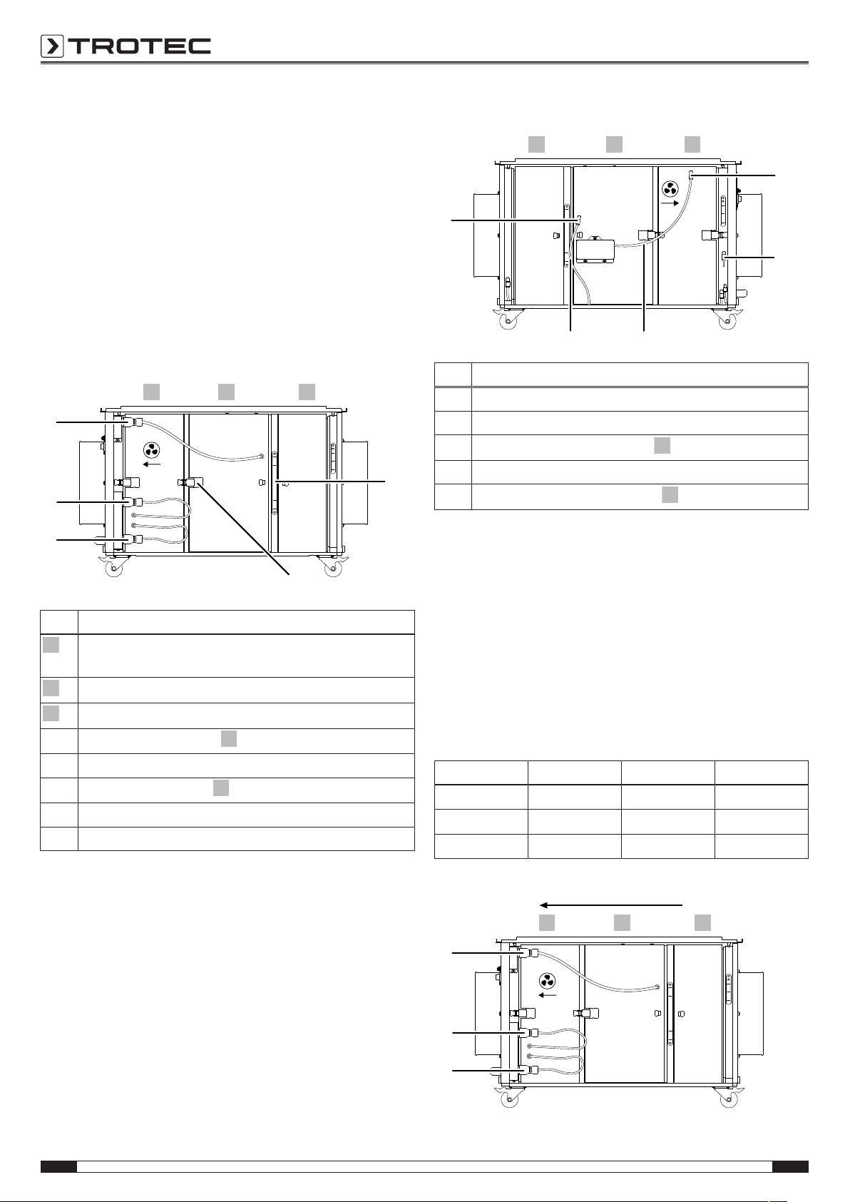
Configuration B
3
2
1
I
II
III
9
10
1
2
3
2
3
3
2
1
11
12
13
S1 S2
3
2
3
2
1
I
II
III
Here air is usually lead from a contaminated area into a clean
area, e.g. as filtered fresh air supply. Suspended matter as per
EN1822-1:1998 up to filter classH14 can be filtered, a higher
filtration efficiency is possible with a reduced air volume. The
filter ladder is operated at excess pressure, i.e. with terminal
fine filter: the fan is to be arranged upstream of the main filter
FILTER BOX2.
The TACseries is equipped with Vario-shift function. This
means that the filter elements can be variably arranged for all
application scenarios and in line with the regulations.
Side view electrics:
Side view sensor hose side:
No. Designation
S1 sensor hoseS1
S2 sensor hoseS2
11
measuring position for fan box
12 measuring position for frame (here with dummy plug)
13
measuring position for filter box
No. Designation
PRE-FILTER BOX: COARSE FILTERG and/or FINE
FILTERF
FILTER BOX: HEPA filter or bag filter
FAN BOX
I
connection for filter box
II connection for fan control
III
connection for fan box
9 tensioning frame
10 tension lock
Arranging and connecting filter boxes
For maximum efficiency bag and Z-line filters are to be
assembled vertically.
1. Place PRE-FILTER BOX1 with inserted filter to the first
position behind the air inlet opening.
2. Insert FILTER BOX2 and FAN BOX3 according to the
desired configuration.
3. Insert the tensioning frame behind PRE-FILTER BOX1.
4. Close all tension locks, both on the side of the electrics
and on the sensor hose side.
5. Connect the cable connections on the side of the electrics
to the corresponding plugs:
Plug Cable Connection
CABLE 1
CABLE 2
CABLE 3
black grey III
white black II
black black I
ConfigurationA:
8 EN
air cleaner TAC 1500 / TAC 3000
Page 9

ConfigurationB:
3
2
1
I
II
III
3
2
1
11
12
13
S1 S2
3
2
1
11
12
13
S1
S2
A
B
C
C
D
Then connect the two sensor hoses on the sensor hose side in
accordance with the selected configuration:
Configuration A
(11): sensor hoseS2=> fan box3
(12): dummy plugB=> frame
(13): sensor hoseS1=> filter box2
Note
Push the sensor hoses firmly into the corresponding
sensor socket until the hose securely clicks into place.
The dummy plug has to be relocated depending on the
configuration – for proper functioning the sensor
sockets must not remain open.
In order to remove hose or dummy plug, press the outer ring of
the measuring point and pull hose or dummy plug at the same
time.
Configuration B
(11): sensor hose S1=> fan box3
(12): sensor hoseS2=> frame
(13): dummy plugB=> filter box2
Start-up
When positioning the device, observe the minimum distance
from walls or other objects as described in the Technical data
chapter.
EN 9
air cleaner TAC 1500 / TAC 3000
Page 10
• Before restarting the device, check the condition of the
power cable. If there are doubts as to the sound condition,
contact the customer service.
• Set the device up in an upright and stable position.
• Do not create tripping hazards when laying the power
cable or other electric cables, especially when positioning
the device in the middle of the room. Use cable bridges.
• Make sure that extension cables are completely unrolled.
• Position the device near the source of air contamination.
• When positioning the device, keep a sufficient distance to
heat sources.
• Make sure that no curtains or other objects interfere with
the air flow.
• Make sure that the air inlet and outlet are not obstructed.
Installation of the device in the room, the air of which is to
be purified
• When positioning the device, make sure it is located in the
centre of the room the air of which is to be cleaned.
Alternatively, you can also position the device near the
source of air contamination.
• Prior to operation you have to ensure that the filters have
been installed in the device as desired.
• Also check, whether the pressure sensors are connected
correctly. If the device, during operation, emits a warning
of a filter being spent, the respective filter has to be
replaced.
If the device issues a warning, although a new filter has
only just been inserted, check whether all sensor hoses
are firmly attached.
• The device works in recirculation mode, this means that
the contaminated air enters the air cleaner via the air inlet
opening and is blown out through the air outlet opening in
purified state.
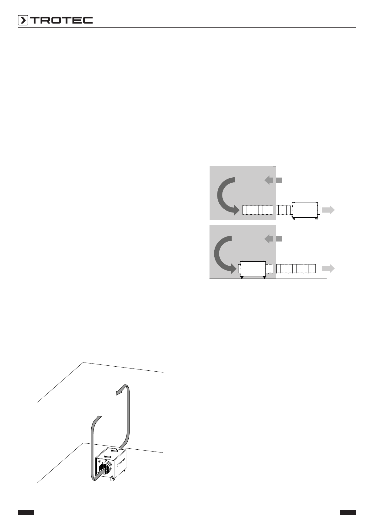
Air purification in sealed off area via air circulation:
Installation of the device outside of the room, the air of
which is to be purified
The device can be connected in either recirculation or
ventilation mode.
• In recirculation mode, the air to be cleaned is led via a
hose from the room into the air inlet opening of the device.
The purified air is fed through another hose from the air
outlet opening and back into the room.
• In ventilation mode, the air to be cleaned is led via a hose
from the room into the air inlet opening of the device. This
creates a slight negative pressure in the room. Clean, fresh
air flows in from outside.
Installation variants for maintaining the pressure:
When connecting hoses, the following must be observed:
• The used pipes and hoses must be designed for the
available static compression of the fans. They should
preferably be laid in a straight line and at full length. 7.6m
of air hose each can be connected to the air inlet and air
outlet openings of the device.
• There ought to be a minimum distance of 1m between air
inlet and air outlet opening.
Connecting the power cable
• Insert the mains plug into a properly secured mains
socket.
10 EN
air cleaner TAC 1500 / TAC 3000
Page 11
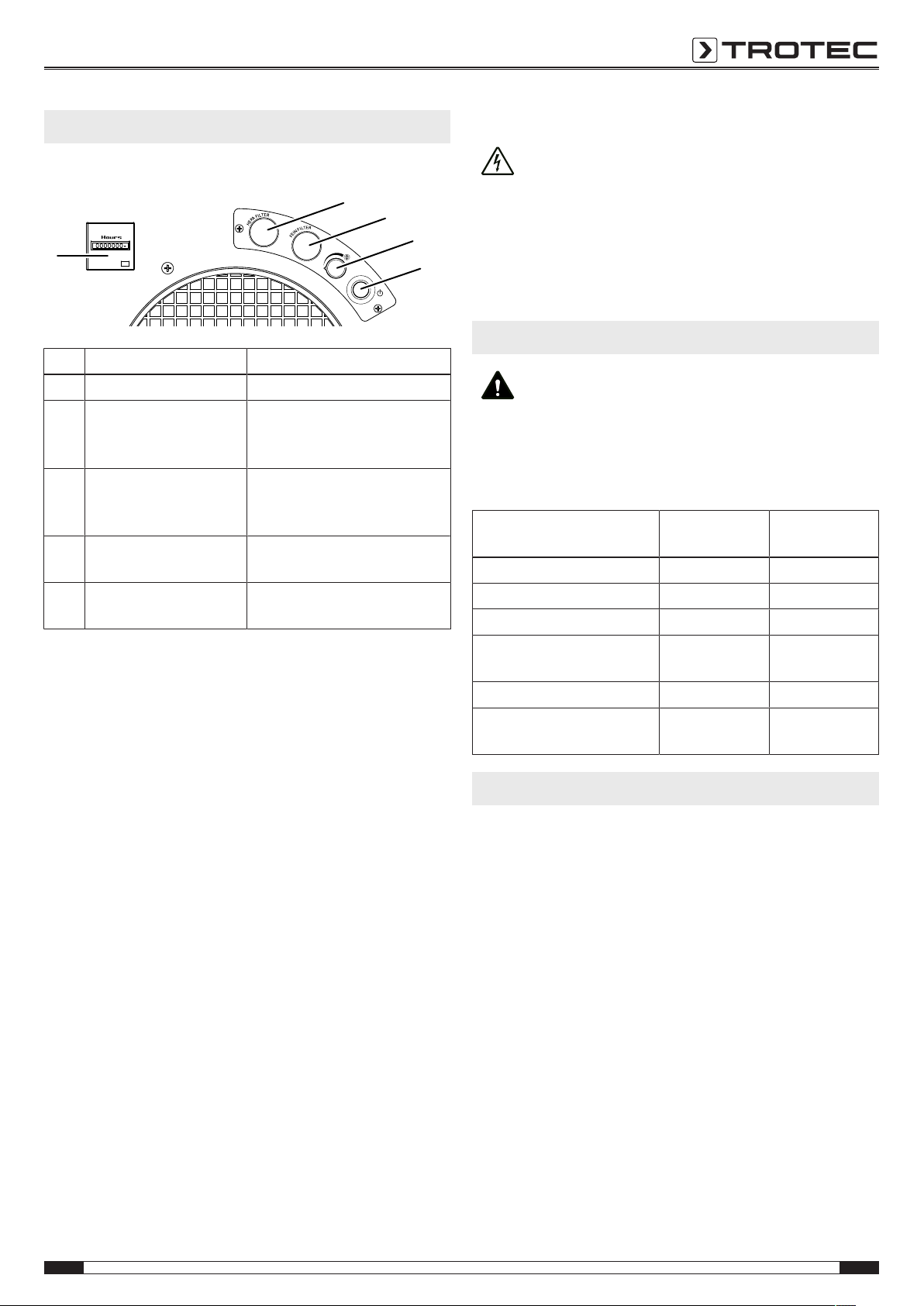
Operation
6
18
19
20
21
Operating elements
No. Designation Meaning
6 Operating hours counter Indication of operating hours
18 Visual and acoustic filter
change indicator
FILTER BOX2
19 Visual and acoustic filter
change indicator
PRE-FILTER BOX1
20 Air volume control dial For setting the desired air
21 Power button For switching the device on or
Switching the device on
Once you have positioned the device as described in the
Start-up chapter, you can switch it on.
1. Ensure that air inlet and outlet are not covered.
2. Turn the air volume control dial(20) counter-clockwise to
the lowest air volume.
3. Press the powerbutton(21).
ð The power button(21) lights up.
Indication of required HEPA or
bag filter change
Indication of required coarse or
fine filter change
volume
off
Shutdown
Warning of electrical voltage
Do not touch the mains plug with wet or damp hands.
• Switch off the device.
• Hold onto the mains plug while pulling the power cable out
of the mains socket.
• Clean the device according to the Maintenance chapter.
• Store the device according to the Storage chapter.
Available accessories
Warning
Only use accessories and additional equipment
specified in the instructions.
Using insertion tools or accessories other than those
specified in the instructions may cause a risk of injury.
Designation Article number
TAC1500
Article number
TAC3000
G4 Z-line filter 7.160.000.404 7.160.000.428
F7 pleated filter cartridge 7.160.000.409 7.160.000.429
F7 bag filter 7.160.000.414 7.160.000.430
H13 HEPA filter approved
7.160.000.424 7.160.000.431
for dust classH
Spray paint filter 7.160.000.416 7.160.000.432
Air transport hose Tronect
6.100.001.200 6.100.001.205
SP-T, length7.6 m
Errors and faults
Adjusting the air volume
By use of the infinitely variable air flow regulation you can adjust
the fan speed and thus regulate the air flow rate of the device.
With the filter arrangement G4, F7 andH13 to meet the
requirements of dust classH, the device with connected
exhaust air hose (7.6m, laid in 290°arcs) reaches an air flow
rate of:
• TAC 1500: 600m³/h
• TAC 3000: 1150m³/h
If the filter change indicator(18) or(19) warns that a filter
change will soon be required, the following min. air flow rate
will still be ensured:
• TAC 1500: 500m³/h
• TAC 3000: 1000m³/h
Exchange the corresponding filters in a timely manner.
1. To increase the air volume, turn the air volume control
dial(20) clockwise.
2. To decrease the air volume, turn the air volume control
dial(20) counter-clockwise.
EN 11
The device has been checked for proper functioning several
times during production. If malfunctions occur nonetheless,
check the device according to the following list.
The device does not start:
• Check the power connection.
• Check the power cable and mains plug for damages.
• Check the on-site fusing.
• Wait for 10minutes before restarting the device. If the
device is not starting, have the electrics checked by a
specialist company or by Trotec.
The device is loud or vibrates:
• Check whether the device is set up in a stable and upright
position.
The device gets very warm, is loud or loses power:
• Check the air inlets and air filters for dirt. Remove external
dirt.
air cleaner TAC 1500 / TAC 3000
Page 12

The device gives off an unpleasant odour:
• Smoke, e.g. dense tobacco smoke, may produce odours
and contaminations in the air. Ventilate the room.
Note
Wait for at least 3 minutes after maintenance and
repair work. Only then switch the device back on.
Your device still does not operate correctly after these
checks?
Please contact the customer service. If necessary, bring the
device to an authorized specialist electrical company or to
Trotec for repair.
Maintenance
Activities required before starting maintenance
Warning of electrical voltage
Do not touch the mains plug with wet or damp hands.
• Switch the device off.
• Hold onto the mains plug while pulling the power cable out
of the mains socket.
Visual inspection of the inside of the device for dirt
1. Remove the air filters.
2. Use a torch to illuminate the openings of the device.
3. Check the inside of the device for dirt.
4. If you see a thick layer of dust, clean the inside of the
device with a vacuum cleaner.
5. Reinsert the air filters.
Warning of electrical voltage
Tasks which require the housing to be opened
must only be carried out by authorised specialist
companies or by Trotec.
Note
Observe the overvoltage protection.
The device comes equipped with an overvoltage
protection. When checking for electrical safety, please
bear in mind that the test voltage has to be reduced to
250V.
Cleaning the housing
Clean the housing with a soft, damp and lint-free cloth. Make
sure that no moisture enters the housing. Protect electrical
components from moisture. Do not use any aggressive cleaning
agents such as cleaning sprays, solvents, alcohol-based or
abrasive cleaners to dampen the cloth.
Cleaning the inside of the device
1. First remove the filters and the filter frame as described in
the Assembly and start-up chapter.
2. Clean the inside of the device and the filter frame with a
soft, damp and lint-free cloth. Make sure that no moisture
enters the housing. Protect electrical components from
moisture. Do not use any aggressive cleaning agents such
as cleaning sprays, solvents, alcohol-based or abrasive
cleaners to dampen the cloth.
3. Reinsert the filters and the filter frameinto the device.
Changing the filter(s)
The filters must be changed if the filter change indicator for
FILTER BOX2(18) or PRE-FILTER BOX1(19) lights up during
operation and an acoustic signal is emitted.
If a filter needs to be replaced, please proceed as described in
the Inserting the filters section in the Assembly and start-up
chapter.
12 EN
air cleaner TAC 1500 / TAC 3000
Page 13

Technical annex
Technical data
Parameter Value
Model TAC1500 TAC3000
Article number 1.580.000.105 1.580.000.115
Recommended amount of air
500 m3/h 1000 m3/h
for dust classH
Dust class
(as per DIN60335-2-69)
dust classH (transmittance ≤0.005%) for substances with a max. allowable concentration of
≤0.1 mg/m³, carcinogenic hazardous substances as per GefStoffV §11 (Ordinance on
Hazardous Substances), TRGS 905 or 906 (Technical Rules for Hazardous Substances),
approvable for asbestos abatement as per TRGS519
Motor power 175 W 450 W
Mains connection 1/N/PE ~230V/ 50–60Hz 1/N/PE ~230V/ 50–60Hz
Nominal current 1.4 A 2.8 A
Connection cable CEE7/7, cable length 3m
rubber conduit (H05RR-F3G1) length= 3.5m
Air transport hose connector
200 mm 250 mm
inlet/outlet side
Sound level
61 dB(A) 65 dB(A)
(at a distance of 1m)
Dimensions
705x 362x 377mm 833x 460x 532mm
(lengthx widthx height)
Weight 22kg 36kg
Recommendation for filter combinations specific to the
TAC1500 TAC3000
application and corresponding room size suitability
suitable for rooms sized up to
Fields of application Filter combination m
3
2
m
1)
3
m
2
m
Coarse dust 2) (≤3ACH6)) G4 220 75 500 170
Fine particulates 3) (≤3ACH6)) G4 + F7 to F9 110 37 270 90
Suspended matter 4) (≤3ACH6)) G4 + H13 50 17 100 34
Hygienic areas 5) (≤3ACH6)) G4 + H13 35 12 70 23
1)
With an assumed room height of 3m; 2) Typical coarse dust tasks: sawing, filing; 3) Typical fine dust tasks: restoration works with
materials containing minerals or glass wool; 4) Typical suspended matter tasks: grinding, asbestos abatement or mould
remediation, mineral dusts etc.; 5) H13 downstream; 6) Air exchange per hour
Optional equipment TAC1500 TAC3000
Guiding wheels with pneumatic tyres, traceless on request on request
Trestle rollers (instead of guiding wheels) on request on request
Fork pockets for fork lifts on request on request
EN 13
air cleaner TAC 1500 / TAC 3000
Page 14

Performance charts
A
E
C
F
D
B
14 EN
air cleaner TAC 1500 / TAC 3000
Page 15
A Fan
B Recommended amount of air for dust classH
C With G4+H13filter combination (approval for dust
classH) and air transport hose*
D With G4+F7filter combination and air transport hose*
E With G4filter and air transport hose*
With spray paint filter and air transport hose*
F Without filter, with air transport hose*
* Connected to the pressure side, standard length 7.6m, laid
with one 90°arc. When the air hose is laid stretched and
arc-free, an increase of air volume by up to 25% is
possible!
Disposal
The icon with the crossed-out waste bin on waste
electrical or electronic equipment stipulates that this equipment
must not be disposed of with the household waste at the end of
its life. You will find collection points for free return of waste
electrical and electronic equipment in your vicinity. The
addresses can be obtained from your municipality or local
administration. For further return options provided by us please
refer to our website www.trotec24.com.
The separate collection of waste electrical and electronic
equipment aims to enable the re-use, recycling and other forms
of recovery of waste equipment as well as to prevent negative
effects for the environment and human health caused by the
disposal of hazardous substances potentially contained in the
equipment.
Declaration of conformity
The text below sets out the contents of the declaration of
conformity. The signed declaration of conformity can be found
at https://hub.trotec.com/?id=42768.
Declaration of conformity
in accordance with the ECMachinery Directive 2006/42/EC,
AnnexII, Part1, SectionA
Herewith, we– TrotecGmbH– declare that the machinery
designated below was developed, constructed and produced in
compliance with the requirements of the ECMachinery
Directive in the version 2006/42/EC.
Product model/ Product:
Product type:
Year of manufacture as of:
Relevant EUdirectives:
• 2011/65/EU: 1July 2011
• 2014/30/EU: 29March 2014
Applied harmonised standards:
• EN ISO 12100:2010
• ENISO 13849-1:2015
• ENISO 13857:2008
• EN 55011:2009
• EN60204-1:2006
• EN 60335-1:2012/AC:2014
• EN 60335-2-65:2003/A11:2012
• EN 61000-6-1:2007
• EN 61000-6-3:2007+A11:2011+AC:2012
Applied national standards and technical specifications:
• ENISO 14118:2018
• EN 60335-2-65:2003/A1:2008
Manufacturer and name of the authorised representative of
the technical documentation:
Trotec GmbH
Grebbener Straße 7, D-52525 Heinsberg
Phone: +49 2452 962-400
E-mail: info@trotec.de
TAC 1500
TAC 3000
air cleaner
2019
Place and date of issue:
Heinsberg, 30.09.2013
Detlef von der Lieck, Managing Director
EN 15
air cleaner TAC 1500 / TAC 3000
Page 16

Trotec GmbH
Grebbener Str. 7
D-52525 Heinsberg
+49 2452 962-400
+49 2452 962-200
info@trotec.com
www.trotec.com
 Loading...