

Page 1

NORMAL.DOT Gespeichert in:G:\Support\Dokumentationen_CDs\8003Speedy\Service Manual\Servicemanual 8003.doc Gespeichert am:2003/03/10
max Version 14
Seite 1 von 87
I N D I V I D U A L M A R
K I N G S Y S T E M S
SERVICE MANUAL
8003 Trotec Speedy C12
8003 Trotec Speedy C25
8003 Trotec Speedy C50
8003 Trotec Speedy C100
Trotec Produktions- u, Vertriebs GmbH
Linzer Straße 156
A-4600 Wels
Tel: ++43/7242/239-0
Fax: ++43/7242/239-7380
E-Mail: TROTEC@trodat.net
Version 1.1
January 1999
Page 2

NORMAL.DOT Gespeichert in:G:\Support\Dokumentationen_CDs\8003Speedy\Service Manual\Servicemanual 8003.doc Gespeichert am:2003/03/10
max Version 14
Seite 2 von 87
I N D I V I D U A L M A R K I N G S Y S T E M S
This publication and it´s contents are proprietary to Trotec Wels and are intended
solely for the contractual use of Trotec customers.
This publication and it´s contents may not be reproduced or distributed for any other
purpose without the written permission of Trotec Wels.
Notice
Trotec Wels does not assume any liability arising out of the application or use of any
products, curcuits or software described herein. Neither does it convey a license
under it´s patent rights nor the patent rights of others. Trotec Wels further reserves
the right to make any changes in any products described herein without notice. This
document is subject to change without notice.
CAUTION
Use of controls or adjustments or performance of procedures other than
those specified herein may result in hazardous laser radiation exposure.
Page 3

NORMAL.DOT Gespeichert in:G:\Support\Dokumentationen_CDs\8003Speedy\Service Manual\Servicemanual 8003.doc Gespeichert am:2003/03/10
max Version 14
Seite 3 von 87
I N D I V I D U A L M A R K I N G S Y S T E M S
Table of contents
1. Main components of the Speedy laser engraver...................................................................5
2. Safety information.................................................................................................................7
General...............................................................................................................................................7
Laser Safety .......................................................................................................................................9
US laser classes.............................................................................................................................................. 9
Safety Interlock System............................................................................................................................... 11
Dangers of Electricity......................................................................................................................12
Emission indication and safety labeling........................................................................................13
Light Emitting Diodes.................................................................................................................................. 13
Audible Warning ......................................................................................................................................... 13
Safety Labels ............................................................................................................................................... 14
3. Laser beam alignment on Speedy.......................................................................................15
4. Laser pointer adjustment ....................................................................................................20
5. Replacing the laser tube...................................................................................................... 22
Measuring the laser power:............................................................................................................23
Laser tube replacement (12W and 25W) ......................................................................................25
Laser tube replacement (50W and 100W) ....................................................................................26
6. Adjusting the Software........................................................................................................28
Adjusting the tickle power..............................................................................................................28
Adjusting the Power Correction factor CL:.................................................................................30
Adjusting the Offset parameters: ..................................................................................................31
Overtook adjustment:.....................................................................................................................33
Tab „correction“ in the service setup............................................................................................34
Tab „acceleration“ in the service setup.........................................................................................35
7. Adjusting the Hardware......................................................................................................36
Ruler adjustment and rectangularity adjustment of the motion system ...................................36
How to check the ruler position................................................................................................................... 37
Ruler adjustment.......................................................................................................................................... 38
Rectangularity adjustment of the motion system.......................................................................................... 38
Table adjustment.............................................................................................................................40
8. Servicing the X axis.............................................................................................................44
9. Special instructions for X-belt tensioning..........................................................................50
10. Instructions for changing the X-gearing assembly.......................................................... 53
11. Servicing the Y axis left part.............................................................................................56
Page 4

NORMAL.DOT Gespeichert in:G:\Support\Dokumentationen_CDs\8003Speedy\Service Manual\Servicemanual 8003.doc Gespeichert am:2003/03/10
max Version 14
Seite 4 von 87
I N D I V I D U A L M A R K I N G S Y S T E M S
12. Servicing the Y axis right part ..........................................................................................60
13. The electric system of the Speedy......................................................................................63
Block wiring diagram .................................................................................................................................. 64
Connector Assignment................................................................................................................................. 65
Checking the different components: ............................................................................................................ 66
14. Firmware Update...............................................................................................................67
Steps for updating the firmware................................................................................................................... 67
15. Network installation of Trotec laser engravers................................................................ 69
16. Software tips&tricks..........................................................................................................72
Rastering images in Corel Draw................................................................................................................. 72
How to produce a Seal Press........................................................................................................................ 73
17. Marking metals using metal mark paint.......................................................................... 74
18. Speedy error codes.............................................................................................................75
Software feedback...........................................................................................................................75
Hardware feedback.........................................................................................................................78
19. FAQ´s.................................................................................................................................80
20. Recommended service intervals........................................................................................ 83
Warranty Regulations.....................................................................................................................83
Recommended replacement intervals for wear-and-tear parts..................................................85
21. Recommended tools...........................................................................................................86
22. Recommended spare parts Speedy - Starter Kit ............................................................. 87
Page 5

NORMAL.DOT Gespeichert in:G:\Support\Dokumentationen_CDs\8003Speedy\Service Manual\Servicemanual 8003.doc Gespeichert am:2003/03/10
max Version 14
Seite 5 von 87
I N D I V I D U A L M A R K I N G S Y S T E M S
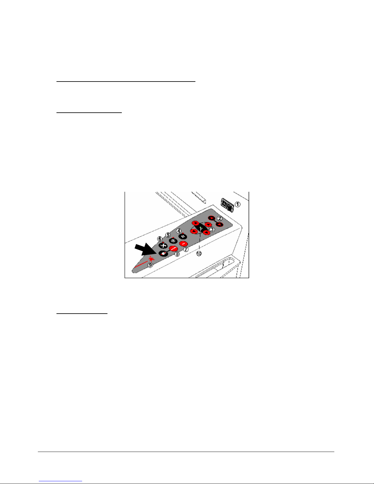
1. Main components of the Speedy laser engraver
Page 6

NORMAL.DOT Gespeichert in:G:\Support\Dokumentationen_CDs\8003Speedy\Service Manual\Servicemanual 8003.doc Gespeichert am:2003/03/10
max Version 14
Seite 6 von 87
I N D I V I D U A L M A R K I N G S Y S T E M S
1 service socket 15 Power supply
2 autofocus sensor 10 X-axis
3 focussing head 11 keypad
4 engraving table 12 front lid
5 Y-axis connector 13 power socket
6 Polycarbonate door 14 service access panel
7 Laser tube cover 16 right interlock front lid
8 Exhaust connector 18 maintenance panel
9 Product ID label
Page 7

NORMAL.DOT Gespeichert in:G:\Support\Dokumentationen_CDs\8003Speedy\Service Manual\Servicemanual 8003.doc Gespeichert am:2003/03/10
max Version 14
Seite 7 von 87
T H E U L T I M A T E M A R K
I N G S O L U T I O N
2. Safety information
Please read this chapter before operating or servicing a Speedy laser system!
General
The Speedy is an industrial apparatus with a high level of security. To guarantee a
safe operation it is necessary to know potential dangers and avoid risks. The
dangers can be classified in three categories:
ì Dangers caused by the laser beam
ì Dangers caused by electricity
ì mechanical dangers
General Safety Instructions
When working with the laser engraver please take note of the following safety
instructions:
1. Operation and service of the Speedy may only be performed by trained
personnel.
2. Direct exposure of skin or eyes to laser radiation may cause severe injuries.
The correct operation and service according to the manual can prevent
hazards. Operators may perform procedures required inside the housing
only through the interlocked door. They must never attempt to defeat the
door interlocks nor remove non interlocked portions of the housing.
3. The laser beam can ignite flammable materials. Therefore a fire
extinguisher should always be nearby. Do not store flammable materials
near or inside the laser engraver.
Page 8

NORMAL.DOT Gespeichert in:G:\Support\Dokumentationen_CDs\8003Speedy\Service Manual\Servicemanual 8003.doc Gespeichert am:2003/03/10
max Version 14
Seite 8 von 87
T H E U L T I M A T E M A R K
I N G S O L U T I O N
Working with the laser or setting the system to service mode without
supervision is not permitted.
4. Many materials, especially non-anodized aluminium, copper, silver and
gold, cannot be engraved with the laser engraver due to the very low
absorption of laser radiation. This means that most of the energy of the
laser beam is reflected. Therefore those materials must not be present in
the laser beam path as otherwise a reflected laser beam could destroy the
cover of the laser unit.
5. Beam adjustment may only be done by trained personnel. Otherwise there
could be uncontrolled emission of laser radiation. There are only limited
possibilities to adjust the mirrors due to a mechanic restriction. These
restrictions may only be altered by authorized personnel.
6. Before starting to work check whether the engraving of the material can
cause harmful fumes and whether the filters of your exhaust system are
suitable for these fumes. It is emphasized that it is the user’s responsibility
to obey the national and regional threshold values for dusts, fumes and
gases. (The maximum concentration of harmful substances must not be
exceeded). Never use the laser engraver without an exhaust unit with
appropriate filters for the treated material, as cutting or engraving certain
materials can produce vapours. Materials causing toxic or carcinogenic
smokes or fumes must not be treated without an exhaust unit with
appropriate filters. Furthermore it is the user’s responsibility to ensure the
safe removal and disposal of the smokes and particles from the laser
machine according to the national and regional threshold values.
In the US reference should be made to Section 7.3 in the ANSI Z136.11993 Standard for the safe use of lasers, to the exposure criteria in CFR
1910 Subpart Z from the US government, and to the Threshold Limit
Values (TLVs) published by the American Conference of Governmental
Industrial Hygienists (ACGIH).
7. Please refer to the manual of your exhaust system regarding the change
intervals of the filters. We recommend to make a note of the last change of
filters on an adhesive label.
8. PVC (Polyvinylchloride) must not be processed with the laser engraver.
If you have any questions please contact your supplier or Trotec.
Page 9

NORMAL.DOT Gespeichert in:G:\Support\Dokumentationen_CDs\8003Speedy\Service Manual\Servicemanual 8003.doc Gespeichert am:2003/03/10
max Version 14
Seite 9 von 87
T H E U L T I M A T E M A R K
I N G S O L U T I O N
Laser Safety
The safety of a laser apparatus is defined by one of five safety classes: I (1),II (2),
IIIa (3a), IIIb (3b) and IV (4). The Speedy without laser pointer is in the EU safety
class 1 (with an installed laser pointer laser class 2) and therefore presents no
hazard to personnel when properly used during normal operation or routine
maintanance. In the US all machines are classified as classII laser products. This
status is guaranteed by the safety housing and safety devices that are built into the
product.
Please be aware that improper operation of the laser apparatus nullifies this safety
class and allows under certain circumstances the emission of radiation which can be
potentially dangerous.
This laser engraving system contains a carbon dioxide (CO2)-laser class IV (4)
product, which emits an intensive and invisible radiation. Without safety devices
the direct radiation and also diffuse reflected radiation is dangerous.
Please be aware:
The Laser Radiation of a CO2 Laser is Invisible!
US laser classes
As posted by the Center for Devices and Radiological Health (CDRH) regulation 21 CFR 1040.10
and 21 CFR 1040.11, the standard classification for lasers are as follows:
Class I laser product
No known biological hazard. The light is shielded from any possible viewing by a person and the
laser system is interlocked to prevent the laser from being on when exposed. (large laser printers
such as the DEC LPS-40 has a 10mW HeNe driving it which is a Class IIIb laser, but the printer is
interlocked so as to prevent any contact with the exposed laser beam, hence the device produces
no known biological hazard, even though the actual laser is Class IIIb. This would also apply to CD
players and small laser printers, as they are Class I devices).
Class II laser products
Power up to 1 milliwatt. These lasers are not considered a optically dangerous device as the eye
reflex will prevent any occular damage. (I.E. when the eye is hit with a bright light, the eye lid will
automatically blink or the person will turn thier head so as to remove the bright light. This is called
the reflex action or time. Class II lasers won't cause eye damage in this time period. Still, one
wouldn't want to look at it for an extended period of time.) Caution labels (yellow) should be placed
on the laser equipment. No known skin exposure hazard exist and no fire hazard exist.
Class IIIa laser products
Power output between 1 milliwatt and 5 milliwatt. These lasers can produce spot blindness under
the right conditions and other possible eye injuries. Products that have a Class IIIa laser should
have a laser emission indicator to tell when the laser is in operation. They should also have a
Page 10

NORMAL.DOT Gespeichert in:G:\Support\Dokumentationen_CDs\8003Speedy\Service Manual\Servicemanual 8003.doc Gespeichert am:2003/03/10
max Version 14
Seite 10 von 87
T H E U L T I M A T E M A R K
I N G S O L U T I O N
Danger label and output aperature label attatched to the laser and/or equipment. A key operated
power switch SHOULD be used to prevent unauthorized use. No known skin hazard of fire hazard
exist.
Class IIIb laser products
Power output from 5 milliwatts to 500 milliwatts. These lasers are considered a definate eye
hazard, particularly at the higher power levels, which WILL cause eye damage. These lasers
MUST have a key switch to prevent unathorized use, a laser emission indicator, a 3 to 5 second
time delay after power is applied to allow the operator to move away from the beam path and a
mechanical shutter to turn the beam off during use. Skin may be burned at the higher levels of
power output as well as the flash point of some materials which could catch fire. (I have seen
250mW argons set a piece of red paper on fire in less than 2 seconds exposure time !) A red
DANGER label and aperature label MUST be affixed to the laser.
Class IV laser products
Power output >500 milliwatts. These CAN and WILL cause eye damage. The Class IV range CAN
and WILL cause materials to burn on contact as well as skin and clothing to burn. These laser
systems MUST have:
A key lockout switch to prevent unauthorized use Inter-locks to prevent the system from being
used with the protective covers off Emission indicators to show that the laser is in use Mechanical
shutters to block the beam Red DANGER labels and aperature labels affixed to the laser
The reflected beam should be considered as dangerous as the primary beam. (again, I have seen
a 1,000 watt CO2 laser blast a hole through a piece of steel, so imagine what it would do to your
eye !)
Registration of laser systems
Any laser system that has a power output of greater than 5 milliwatts MUST be registered with the
FDA and Center for Devices and Radiological Health if it has an exposed beam, such as for
entertainment (I.E. Laser light shows) or for medical use (such as surgery) where someone other
than the operator may come in contact with it. (this is called a 'varience' and I have filled them out
and submitted them and they ARE a royal pain in the backside !)
Risks of Laser Radiation:
If the built in safety measures are defeated or the laser is operated with the housing
open, there is a risk of setting clothing or other flammable materials on fire. Laser
energy at a power of up to 150W (Model C100) at a wavelength of 10,6 µm could be
present inside the housing.
Therefore operators can perform procedures required inside the housing only when
the interlocked door has been opened. (A normal user must never defeat the door
interlocks or remove portions of the protective housing, except the machine is not
powered).
Therefore you must under no circumstances neither alter the laser tube unit nor
dismantle it nor set a system to work which has been altered or dismantled!
Page 11

NORMAL.DOT Gespeichert in:G:\Support\Dokumentationen_CDs\8003Speedy\Service Manual\Servicemanual 8003.doc Gespeichert am:2003/03/10
max Version 14
Seite 11 von 87
T H E U L T I M A T E M A R K
I N G S O L U T I O N
Safety Interlock System
Your Speedy is equipped with an integrated safety interlock system which cuts off
the power of the laser tube immediately as soon as one of the doors is opened.
CAUTION
Do not attempt to alter the interlock system as that could result in
hazardous radiation exposure.
CAUTION
Technicians who are performing service procedures must be trained in
laser safety, and if they are defeating interlocks, they must wear laser
protective eyewear designed for the 10,6µm CO2 laser energy.
The top door, front door and the maintenance access panel are interlocked. If the
interlocks are defeated access to laser class IV radiation is possible through any of
these doors.
All other covers are not interlocked.
CAUTION
When a non interlocked cover is opened (and the machine is powered)
access to class IV laser radiation is possible.
These covers are labeled with „DANGER: INVISIBLE LASER RADIATION
WHEN OPEN. AVOID EYE OR SKIN EXPOSURE TO DIRECT OR
SCATTERED RADIATION“
Page 12

NORMAL.DOT Gespeichert in:G:\Support\Dokumentationen_CDs\8003Speedy\Service Manual\Servicemanual 8003.doc Gespeichert am:2003/03/10
max Version 14
Seite 12 von 87
T H E U L T I M A T E M A R K
I N G S O L U T I O N
Dangers of Electricity
When you open the covers of the engraving system there is the danger to get in
contact with parts under high voltage. Therefore it is absolutely necessary that
service and repair work is only done while the power supply is unplugged. In any
case all safety laws and standards in connection with electricity must be obeyed.
IMPORTANT REMARK:
Usually you do not need to get in touch with the electrical and electronic
components. In case you do that when servicing or repairing the laser engraver,
please be sure that you first plug off the power supply.
Page 13
NORMAL.DOT Gespeichert in:G:\Support\Dokumentationen_CDs\8003Speedy\Service Manual\Servicemanual 8003.doc Gespeichert am:2003/03/10
max Version 14
Seite 13 von 87
T H E U L T I M A T E M A R K
I N G S O L U T I O N
Emission indication and safety labeling
Light Emitting Diodes
On the keypad of the laser engraver there is on the left side a red LED (light emitting
diode) which is illuminated when laser radiation is emitted.
If the service plug is used to defeat the door interlocks, the red LED close to the
service button is flashing (which indicates that the machine now is in service mode).
In this case the machine represents a laser class IV (4) product and special safety
provisions are necessary.
emission indicator
Audible Warning
When starting up the laser engraver without closing the cover there is an intermittent
beep. This indicates that the interlock system has not been checked yet. (You can
run the machine only if all interlock switches are closed). Close the cover of the laser
engraver to cause the machine to initialize.
On emitting a laser beam (which is called test pulse) by pressing the „TEST"- and
"SERVICE" button simultaneously there is a beep (as long as you keep the buttons
pressed) to remind you of the possible risks.
Page 14

NORMAL.DOT Gespeichert in:G:\Support\Dokumentationen_CDs\8003Speedy\Service Manual\Servicemanual 8003.doc Gespeichert am:2003/03/10
max Version 14
Seite 14 von 87
T H E U L T I M A T E M A R K
I N G S O L U T I O N
Safety Labels
The laser safety standards require that any removable panels that could permit
access to laser energy include laser safety labels. These labels are visible before
and after opening a cover.
Labels with the name of the manufacturer, date of production, description of the
product, model number, serial number and safety labels are placed on the outer side
of the apparatus. All these labels are mounted when producing the laser engraver.
These labels must not be removed.
If the labels are lost or damaged please contact Trotec. Replacements will be sent to
you free of charge. All labels and their exact place is mentioned in the user manual:
The labeling meets the standards
F 21 CFR 1040 – Laser safety
and
F EN 60825-1(1994)
Page 15

___________________________________________________________________________
NORMAL.DOT Gespeichert in:G:\Support\Dokumentationen_CDs\8003Speedy\Service Manual\Servicemanual 8003.doc Gespeichert am:2003/03/10
max Version 14
Seite 15 von 87
I N D I V I D U A L M A R K I N G S Y S T E M S
3. Laser beam alignment on Speedy
What you need:
laser protection glasses (for CO2 lasers)
the toolbox enclosed to your engraver
masking tape
CAUTION To make sure that there is no laser emission out of a
controlled area establish a limited access area by using non flamable
beam blocking curtains, temporary walls or other enclosures.
CAUTION The laser beam alignment may only be performed by service
technichians that have been trained by Trotec and are familiar with the
hazards from lasers
CAUTION
Never expose any part of your body to the beam as this could result in
serious injuries.
CAUTION
To do the alignment it is absolutely necessary to wear laser protection
glasses.
What you have to know:
The number of the mirrors is counted from the outlet of the laser tube to the
engraving head from one to three.
The whole alignment is done while your machine is running. To make sure the
system works at a suitable power level switch your machine off and on again.
The laser beam is invisible. To make it visible, you use adhesive tape. It is burned at
the spot, where it is hit by the laser beam and shows so a mark.
The tolerable displacement (distance from burned dot to the centre) is one sixth of
the diameter of the mirror or hole where you check the position.
Page 16
___________________________________________________________________________
NORMAL.DOT Gespeichert in:G:\Support\Dokumentationen_CDs\8003Speedy\Service Manual\Servicemanual 8003.doc Gespeichert am:2003/03/10
max Version 14
Seite 16 von 87
I N D I V I D U A L M A R K I N G S Y S T E M S
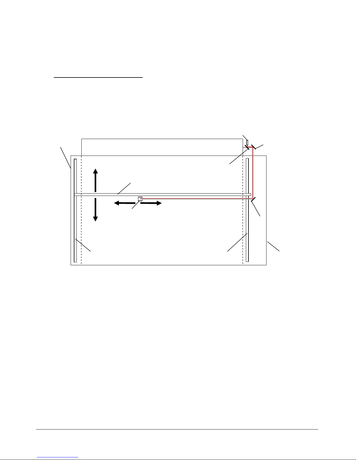
Beam path of the Speedy:
CO2 Laser Tube
Mirror No 2
Mirror No 3
Mirror No 1
Beam coupler
Aiming Laser diode
Beam path of the Speedy model
X-Axis
Left Y-Axis
Right Y-Axis
Maintenance
panel
Service access
panel
Page 17
___________________________________________________________________________
NORMAL.DOT Gespeichert in:G:\Support\Dokumentationen_CDs\8003Speedy\Service Manual\Servicemanual 8003.doc Gespeichert am:2003/03/10
max Version 14
Seite 17 von 87
I N D I V I D U A L M A R K I N G S Y S T E M S
What you have to do:
1. Disassemble the cover on the right side of the machine (10mm allen key).
2. Take your laser protection glasses and remove the grey cover of the first mirror at
the rear of your laser (right side) wearing the sign „DANGER. INVISIBLE LASER
RADIATION WHEN OPEN. AVOID EYE OR SKIN EXPOSURE TO DIRECT OR
SCATTERED RADIATION.“
3. Remove mirrors #2 and #3.
Removal of mirror #2
Removal of mirror #3
mirror unit 3
cover of mirror 1
mirror unit 2
Page 18
___________________________________________________________________________
NORMAL.DOT Gespeichert in:G:\Support\Dokumentationen_CDs\8003Speedy\Service Manual\Servicemanual 8003.doc Gespeichert am:2003/03/10
max Version 14
Seite 18 von 87
I N D I V I D U A L M A R K I N G S Y S T E M S
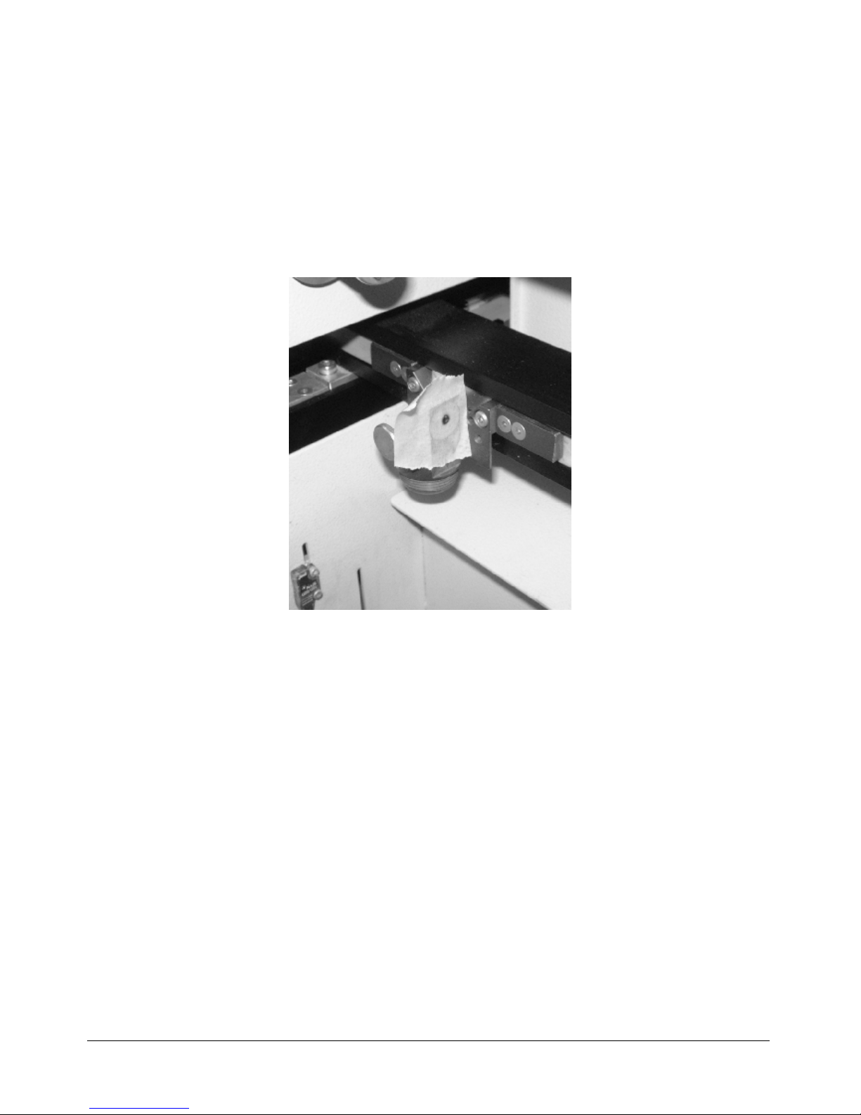
4. Put a piece of masking tape on the hole (black anodized aluminium part) in front
of mirror #2.
alignment of mirror no.1
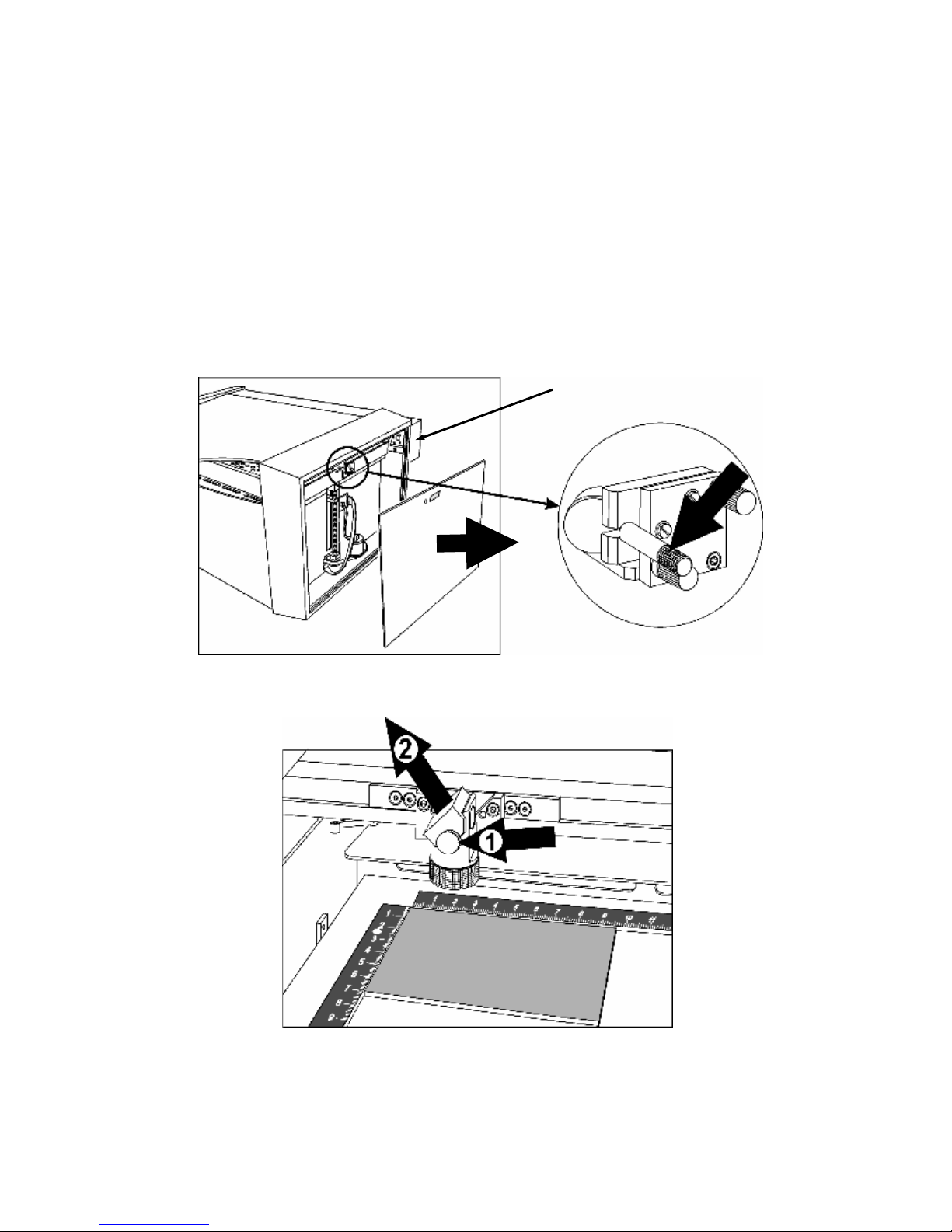
5. Move the x-axis to the top position.
6. Press the test button, keep it pressed and then press the service button until you
see a little mark on the adhesive tape. (This is only possible if all doors are closed
or a service plug is put into the socket). The mark should be in the centre of the
hole. (If you don´t see a mark adjust the two brass screws at mirror #1 until you
can see a mark.
adjustments at mirror #1
7. Move the x-axis to the bottom position.
height adjustment
screw
left-right
adjustment screw
slider fixing screws
slider
Page 19
___________________________________________________________________________
NORMAL.DOT Gespeichert in:G:\Support\Dokumentationen_CDs\8003Speedy\Service Manual\Servicemanual 8003.doc Gespeichert am:2003/03/10
max Version 14
Seite 19 von 87
I N D I V I D U A L M A R K I N G S Y S T E M S
8. Repeat step 6, but this time try to hit the spot that you´ve created first.
9. Repeat steps 5 to 8 until the two spots are exactly at the same place.
10. If the spot is not centered bring it to the center by moving the slider of mirror#1.
11. Replace mirror #2.
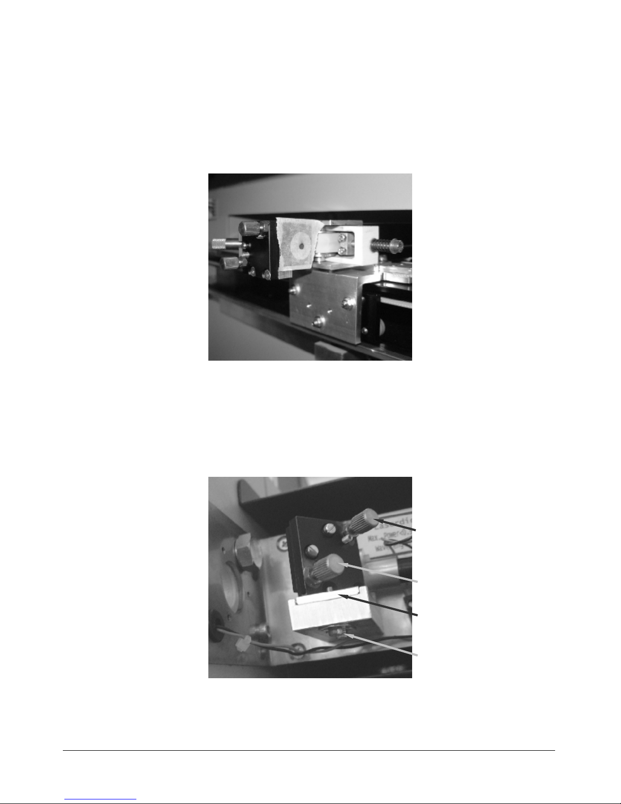
12. Put a piece of masking tape on the hole in front of mirror #3.
checking the beam position at mirror #3
13. Move the engraving head to the top right corner.
14. Again press the test button, keep it pressed and then press the service button
until you see a little mark on the adhesive tape.
15. Move the engraving head to the top left corner and adjust the two brass screws at
mirror #2 until you hit the spot created in step 14.
16. Repeat steps 13 to 15 to check the position. If necessary readjust mirror #2.
17. Move the x-axis to the bottom position and check the alignment on the bottom left
position. If necessary do small corrections at mirror #1.
18. At the end check alignment on all four corners.
19. Assemble all parts again.
20. Now your engraver is aligned properly.
Page 20
NORMAL.DOT Gespeichert in:G:\Support\Dokumentationen_CDs\8003Speedy\Service Manual\Servicemanual 8003.doc Gespeichert am:2003/03/10
max Version 14
Seite 20 von 87
I N D I V I D U A L M A R K I
N G S Y S T E M S
4. Laser pointer adjustment
Attention: To do the laser pointer adjustment it is absolutely necessary to wear laser
protection glasses!
What you need:
laser protection glasses
the toolbox enclosed to your engraver
a philips screwdriver
adhesive tape
What you have to know:
The alignment is done while your machine is running. To make sure the system
works at a suitable power level switch your machine of and on again.
The laser beam is invisible. To make it visible, you use adhesive tape. It is burned at
the spot, where it is hit by the laser beam and shows so a mark.
The tolerable displacement (distance from burned dot to the centre) is one sixth of
the diameter of the mirror or hole where you do the adjustment.
1.) After you´ve installed the laser pointer glue some paper tape on the beam
entrance hole of the engraving head (first remove the last mirror and the lens).
3
Page 21
NORMAL.DOT Gespeichert in:G:\Support\Dokumentationen_CDs\8003Speedy\Service Manual\Servicemanual 8003.doc Gespeichert am:2003/03/10
max Version 14
Seite 21 von 87
I N D I V I D U A L M A R K I
N G S Y S T E M S
2.) Move the engraving head to the upper left corner of the engraving table.
3.) Fire the test pulse by pressing the test button, keeping it pressed and pressing at
the same time the service button, until you can see a small spot on the paper
tape.
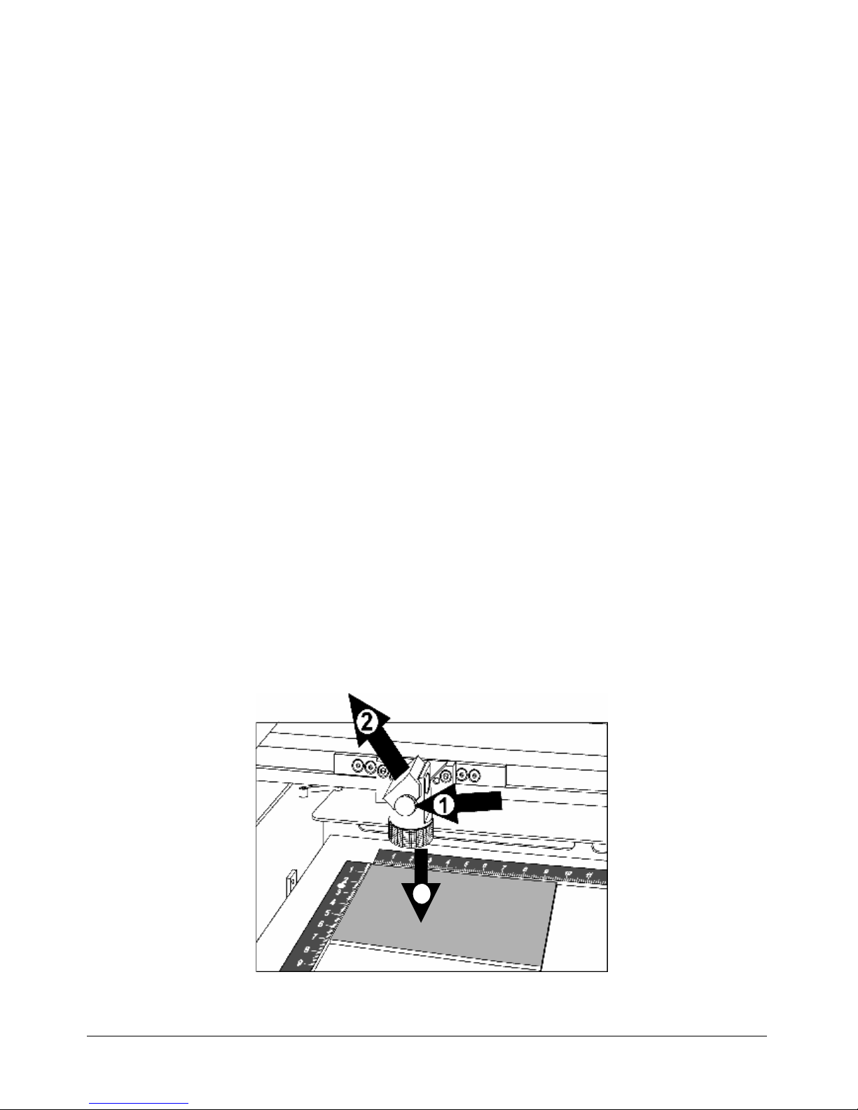
4.) Adjust the three small screws (see attached picture) close to the laser pointer
until the red dot hits exactly the burned spot on the paper tape.
5.) Check the beam position on all four corners of the engraving table. You can get
the highest sensitivity to changes of the pointer position in the lower left corner of
the engraving table.
Adjustment screw
Laserpointer
Page 22

NORMAL.DOT Gespeichert in:G:\Support\Dokumentationen_CDs\8003Speedy\Service Manual\Servicemanual 8003.doc Gespeichert am:2003/03/10
max Version 14
Seite 22 von 87
I N D I V I D U A L M A R K I N G S Y S T E M S
5. Replacing the laser tube
The laser tube is one of the main components of any laser engraver. The Speedy
uses for the 12, 25, 30 and 50W version Synrad tubes, and for the 100 W version a
Coherent tube. The 50 and 100W tubes are liquid cooled, all other tubes are air
cooled.
To make the tube fire it must be
- Connected to the power supply (48V for the 100W unit, for all other
machines 30V)
[On Synrad tubes this will be indicated with a green LED]
- Provided with a control signal (BNC connector, two for the 50W)
The control signal is a 5V TTL signal that comes from the main board.
[if there is a signal Synrad tubes will indicate this with an illuminated red
LED]
Additionally on the 100W machines the coolant velocity must be above 5.7 l/min.
All tubes have an integrated overtemperature protection. If the tube exceeds a
certain limit it is switched off to prevent a damage of the gas/electronics.
The following reasons might cause you to replace the tube:
• A too low laser power
• Fluctuations of laser power (typically jumps from 100% to 50% engraving
depth on a 25W unit, or from 100% to 75% on a 50W machine)
The frequency of these power fluctuations is low (e.g. every 5 minutes)
• Uncontrollable timing behaviour (high frequency effect).
This effect shows shifted start/end points of the pulses so that the image looks
frayed although the mechanics (of the motion system) and software
adjustment are OK.
Page 23
NORMAL.DOT Gespeichert in:G:\Support\Dokumentationen_CDs\8003Speedy\Service Manual\Servicemanual 8003.doc Gespeichert am:2003/03/10
max Version 14
Seite 23 von 87
I N D I V I D U A L M A R K I N G S Y S T E M S
Measuring the laser power:
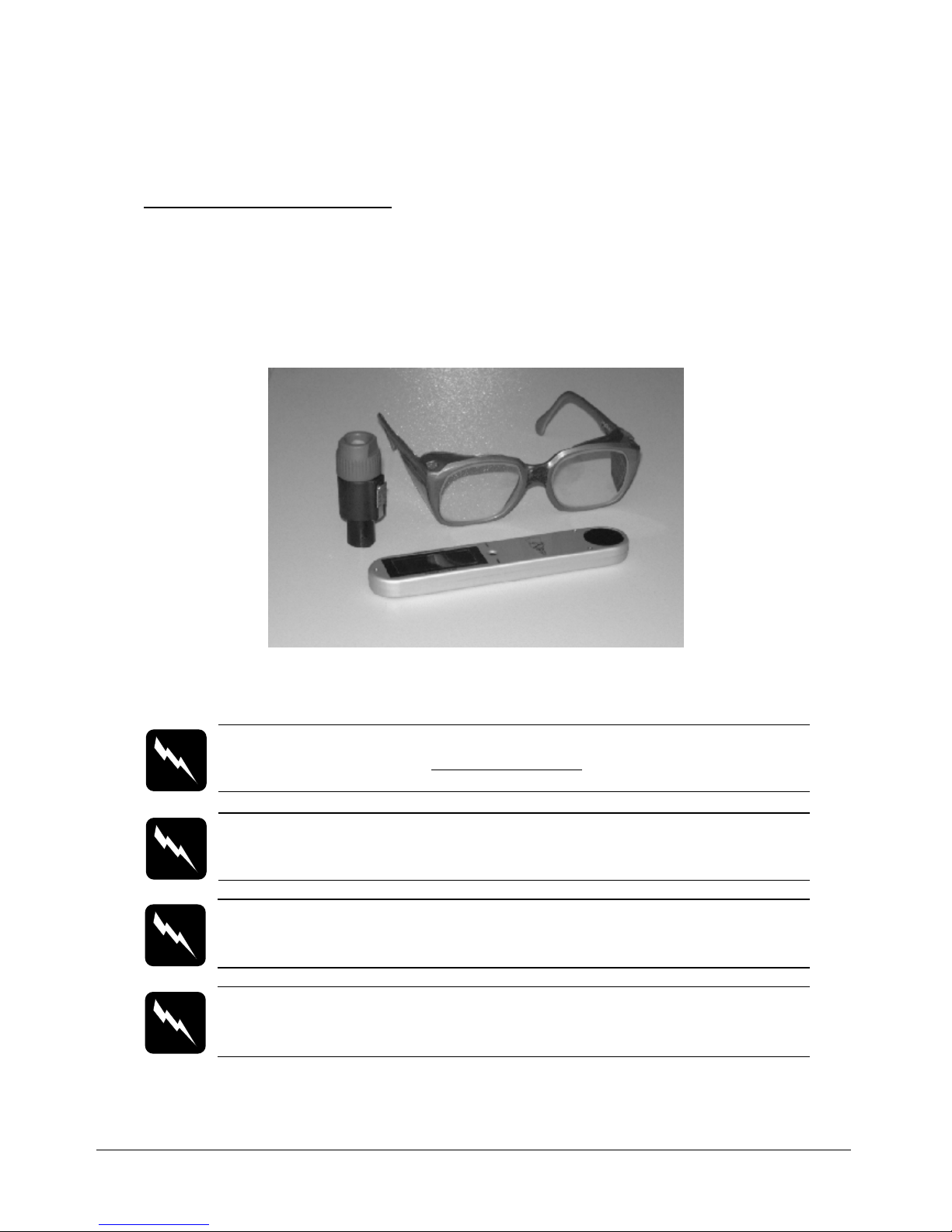
To measure the laser power you need:
1. Laser protective goggles
2. Laser power meter
3. Interlock defeat tool
tools for measuring the laser power
CAUTION To make sure that there is no laser emission out of a
controlled area establish a limited access area by using non flamable
beam blocking curtains, temporary walls or other enclosures.
CAUTION The laser power measurement may only be performed by
service technichians that have been trained by Trotec and are familiar with
the hazards from lasers
CAUTION
Never expose any part of your body to the beam as this could result in
serious injuries.
CAUTION
To do the laser power measurement it is absolutely necessary to wear
laser protection glasses.
Page 24
NORMAL.DOT Gespeichert in:G:\Support\Dokumentationen_CDs\8003Speedy\Service Manual\Servicemanual 8003.doc Gespeichert am:2003/03/10
max Version 14
Seite 24 von 87
I N D I V I D U A L M A R K I N G S Y S T E M S
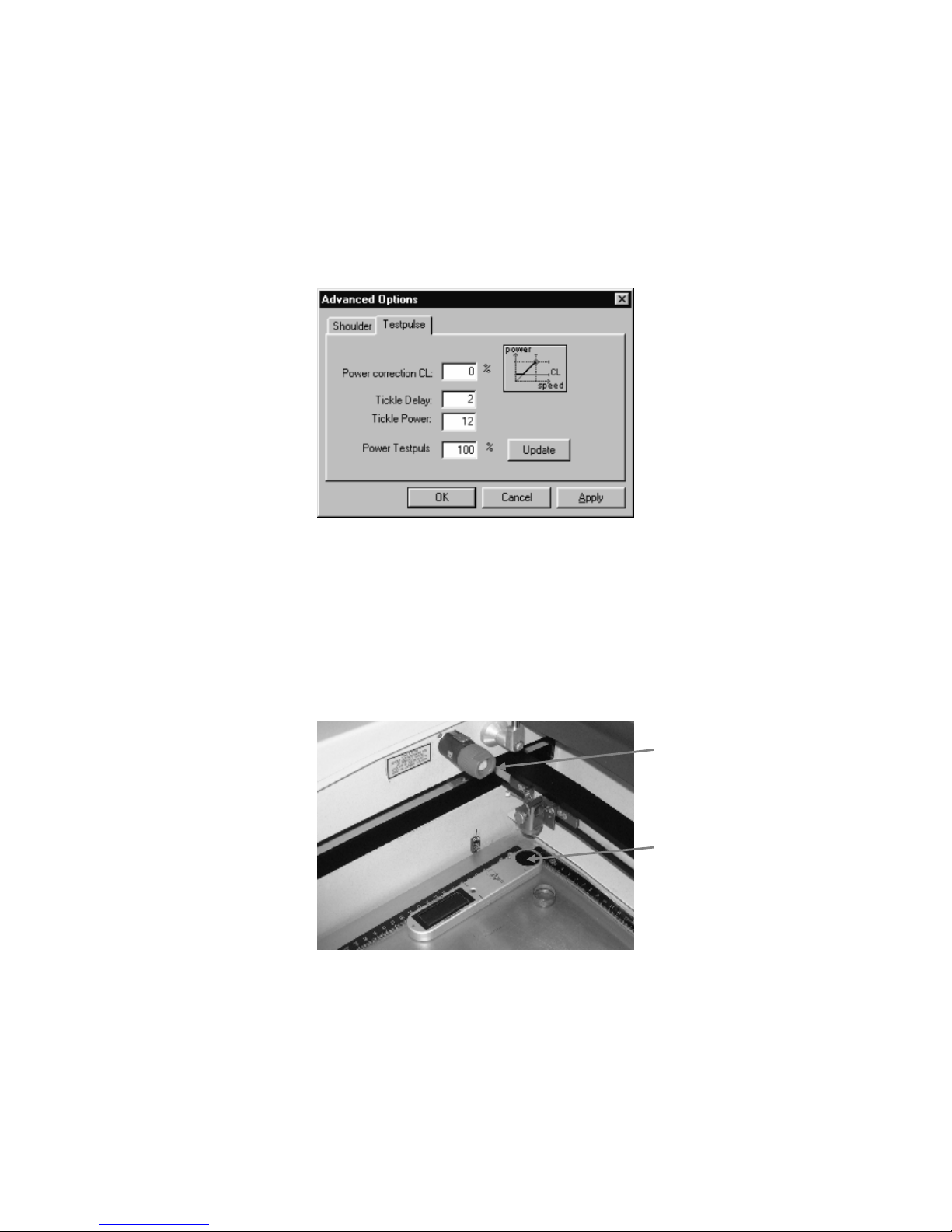
• Open the Trotec manager and connect to the engraver
• Enter the Advanced Options menu (Settings>Advanced options, Tab
Testpulse) and switch Power Testpulse to 100%. Press update.
increasing the test pulse to full power
• Defeat the interlock by plugging the interlock defeat tool into the socket on
the left side of the engraving area.
• Remove the lens
• Put the power meter with the black absorbing area in one of the corners of the
engraving table
• Move the table to a height level so that the distance between engraving head
and target area is approximately four centimetres.
setup for measuring the laser power
• Press the reset button on the power meter and fire the testpulse (press test,
keep it pressed and then press service)
• After some seconds you will hear a beep sound, which indicates that the
measurement has been finished.
• Repeat the procedure in the other corners
interlock
defeat tool
target area of
the power
meter
Page 25

NORMAL.DOT Gespeichert in:G:\Support\Dokumentationen_CDs\8003Speedy\Service Manual\Servicemanual 8003.doc Gespeichert am:2003/03/10
max Version 14
Seite 25 von 87
I N D I V I D U A L M A R K I N G S Y S T E M S
The wattage difference between the four corners should be smaller than 10% of the
average laser power. Otherwise something is wrong with the beam alignment.
In this case measure the power directly at the beam aperture.
Laser tube replacement (12W and 25W)
1. Switch off the Speedy and open the service acces panel using a 10 mm allen
key. Remove also the cover of the electronic compartment.
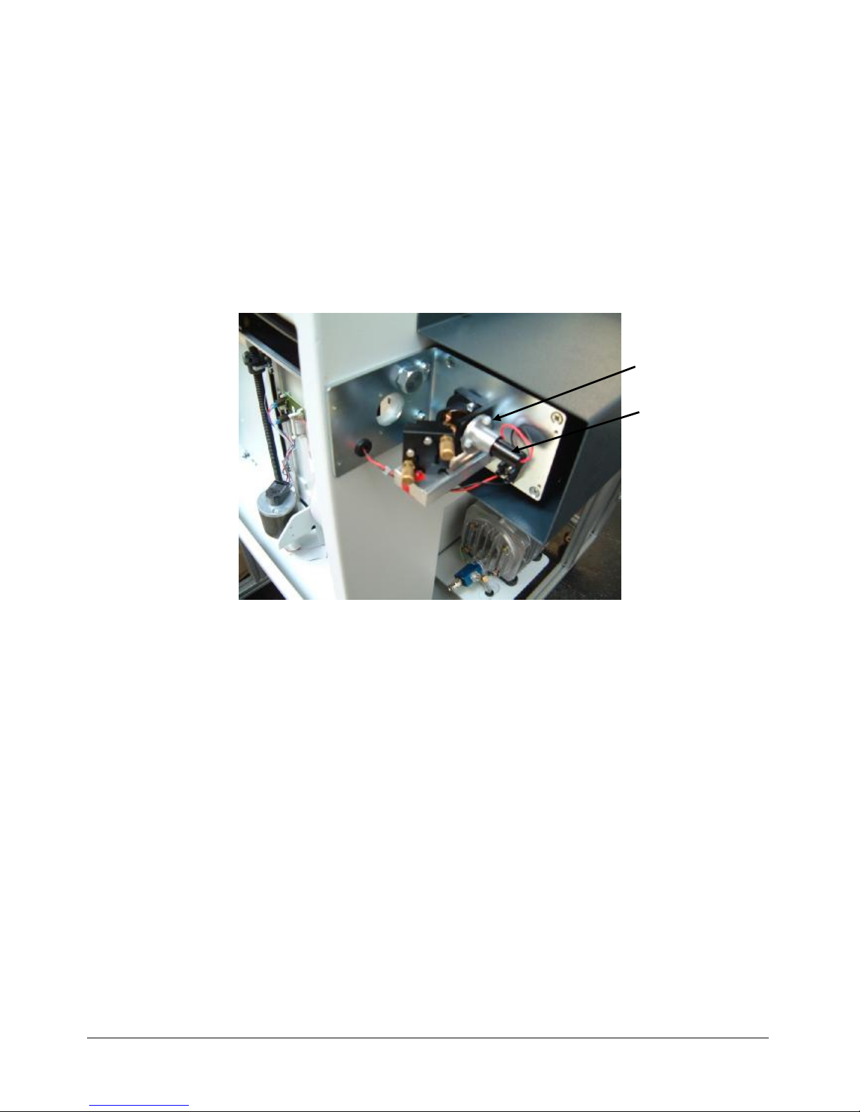
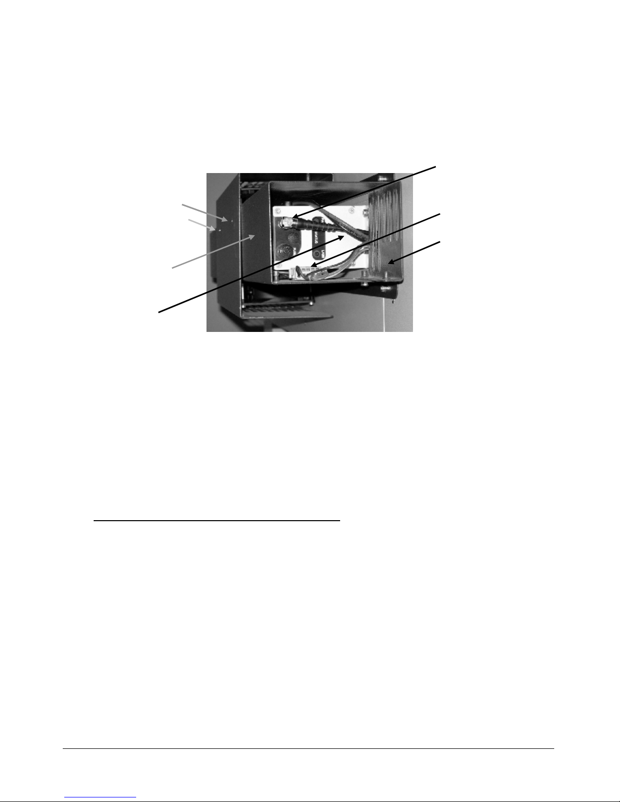
2. Unplug the power connector (black-red) for the lasertube on the main board.
connectors on the power board
3. Remove the protective cover of the cooling fans.
power
connector
Page 26
NORMAL.DOT Gespeichert in:G:\Support\Dokumentationen_CDs\8003Speedy\Service Manual\Servicemanual 8003.doc Gespeichert am:2003/03/10
max Version 14
Seite 26 von 87
I N D I V I D U A L M A R K I N G S Y S T E M S
4. Take out the metal grid and disconnect the cooling fans.
Pull out the black-red power cable.
5. Remove the fan enclosure
6. Pull out the power cable (black-red) and unplug the signal cable on the lasertube.
7. CAUTION: Before you perform that step please ask a second person to assist
you. The risk here is to drop the tube. Loosen the two 4mm screws on the right
side of the tube and remove the four philips screws on the left side (before you
can do that remove the cover of mirror unit 1).
8. Remove the tube
9. Assemble the new tube in the reverse way.
10. After the replacement you´ve to do the beam alignment.
Laser tube replacement (50W and 100W)
1. Switch off the Speedy and open the service acces panel using a 10 mm allen
key. Remove also the cover of the electronic compartment.
2. Unplug the power connector (black-red) for the lasertube on the main board.
3. Remove the tube enclosure.
4. Disconnect the six push fit fittings that are connected to the tube and
disassemble the two that fix the plastic water distributor.
5. Remove also all fittings on the left side of the tube.
6. Pull out the power cable (black-red) and unplug the two signal cables on the
lasertube.
7. CAUTION: Before you perform that step please ask a second person to assist
you. The risk here is to drop the tube. Loosen the two 4mm screws on the right
cooling fan
connector
BNC
connector
metal
grid
fixing
screws of
cooling fan
protective
cover
power
cable
fan
enclosure
Page 27

NORMAL.DOT Gespeichert in:G:\Support\Dokumentationen_CDs\8003Speedy\Service Manual\Servicemanual 8003.doc Gespeichert am:2003/03/10
max Version 14
Seite 27 von 87
I N D I V I D U A L M A R K I N G S Y S T E M S
side of the tube and remove the six philips screws on the left side (before you can
do that remove the cover of mirror unit 1).
8. Remove the tube
9. Assemble the new tube in the reverse way.
10. After the replacement you´ve to do the beam alignment.
11. Pack the tube and ship it back to Trotec.
Page 28

NORMAL.DOT Gespeichert in:G:\Support\Dokumentationen_CDs\8003Speedy\Service Manual\Servicemanual 8003.doc Gespeichert am:2003/03/10
max Version 14
Seite 28 von 87
I N D I V I D U A L M A R K I N G S Y S T E M S
6. Adjusting the Software
Adjusting the tickle power
The tickle pulses are used to keep the plasma inside the tube ionized continuously.
This guarantees a quick response whenever laser power is needed to mark or cut
materials.
If the tickle power is too low, then typical effects are bad contrast for fine details,
missing elements (e.g. a not closed circle) or frayed edges.
If the tickle power is too high you will see shadows on the edges.
There are two settings in the Trotec manager, which are responsible for a correct
excitement of the gas filling. These are:
1. Tickle power
2. Tickle delay
Tickle delay is a setting that should be left at it´s default value of 30. It defines a time
from the end of laser output (to mark the surface) to the start of the tickle pulses
within which no tickles are sent. This delay makes sure that no following pulses are
caused by the tickles immediately after firing.
Tickle power is a parameter that defines the intensity of the tickle pulses.
Reduce it when you see shadows on the edges.
Increase it, when e.g. fine images on anodized aluminium are darker than big ones.
Page 29

NORMAL.DOT Gespeichert in:G:\Support\Dokumentationen_CDs\8003Speedy\Service Manual\Servicemanual 8003.doc Gespeichert am:2003/03/10
max Version 14
Seite 29 von 87
I N D I V I D U A L M A R K I N G S Y S T E M S
To find the correct settings of tickle power do the following steps:
1. Warm up the tube by engraving some rubber stamps at full power.
2. Take a very laser sensitive material e.g. laser plastics or soft wood.
3. Reduce the acceleration of the X-axis (settings>options>service:password
„name“) to 1.
4. Engrave an image (please use the sample file „Abnahmetest Alu“ on the CD in
the folder Samples\QS Spoolfiles [copy it into the Spool directory and alter the file
properties from „read only“ to „archive“] ) into the wood and have a look on the
edges (please use a low speed).
5. If you see shadows reduce tickle power, if there are none increase tickle power.
To make sure that your changes take effect always click on apply in the dialog
window.
shadows beside the engraving, caused by too high tickle power
6. Repeat steps 4 to 6 until you´ve found the setting that is necessary to prevent
shadows, but keeps the tube just below firing.
7. Now you´ve adjusted tickle power.
Note: Before you adjust the edit settings of a tube you should always make sure that
tickle power has been set correctly.
For optimum engraving quality a new adjustment of Edit settings and tickle power is
necessary after a certain lifetime of the tube (Recommended after 1000 hours of
operation).
Page 30

NORMAL.DOT Gespeichert in:G:\Support\Dokumentationen_CDs\8003Speedy\Service Manual\Servicemanual 8003.doc Gespeichert am:2003/03/10
max Version 14
Seite 30 von 87
I N D I V I D U A L M A R K I N G S Y S T E M S
Adjusting the Power Correction factor CL:
The factor CL (menu settings>advanced options>Tab Testpulse) is a minimum
power that will affect the material even when the engraving speed is zero.
The reason why we need a power correction is in the material behavior itself:
Many materials show a nonlinear response. That means when you engrave on the
material with a continuously increased power level the change of color will not have a
linear connection with the change of power. For many materials you need a certain
minimum power level that is necessary (e.g. anodized aluminium: because of the
high heat conductivity, that causes a quick heat transfer you need a relatively high
factor CL≈30) for marking the workpiece. This mimimum power can be adjusted by
setting the power correction factor CL.
Note: The power correction factor must be adjusted for each material individually and
can be changed only in the Trotec manager. For most materials a low value of
CL≈0..3 is OK)
Steps for adjusting the power correction:
1. Create a rectangular cut job (≈ 5 x 5cm)
2. Vector into the material. Set the parameters so that you only mark the surface
and do not cut deep into the material.
3. If the cut line is closed on the corners but is thicker where the lines meet reduce
CL.
4. If the cut line is not closed on the corners increase CL.
5. As soon as you have a closed curve with constant line thickness you´ve found the
correct factor of CL.
Note: This adjustment is only necessary when you want to mark only the surface of a
material. It is not needed for Lasercutting all the way through the material.
A change of the tickle power setting will also affect the correct setting of CL.
Page 31

NORMAL.DOT Gespeichert in:G:\Support\Dokumentationen_CDs\8003Speedy\Service Manual\Servicemanual 8003.doc Gespeichert am:2003/03/10
max Version 14
Seite 31 von 87
I N D I V I D U A L M A R K I N G S Y S T E M S
Adjusting the Offset parameters:
The Speedy uses so called offset parameters (X and Y) to make sure that the zero
position of the software is exactly in the crosspoint of the rulers. This is important for
precise positioning of jobs.
Additionally we use the Z offset to finetune the automatic focus. (only for focussing
using the software)
Tab „Offset“ in the Service menu
An offset is a certain distance from the home position that is given by the limit
switches to the edge of the rulers (for X and Y) or the focus level of the lens (Z).
Whenever you see that the position of your engraving on the table is not the same as
in your desktop publishing program you have to adjust the offsets.
Steps for adjusting the X and Y offsets:
1. Make sure that the ruler angle has been adjusted correctly.
2. Focus your beam on the surface of the rulers and glue some paper tape in the
crosspoint.
3. Move the engraving head to 0/0 (Engraver>move laser)
4. Fire the test pulse until you can see a small spot in the paper tape.
checking the zero position
X
Y
Page 32

NORMAL.DOT Gespeichert in:G:\Support\Dokumentationen_CDs\8003Speedy\Service Manual\Servicemanual 8003.doc Gespeichert am:2003/03/10
max Version 14
Seite 32 von 87
I N D I V I D U A L M A R K I N G S Y S T E M S
5. The distance between this spot and the rulers should be smaller than 0.5mm.
6. If the distance is bigger: between X ruler and spot ⇒ reduce X-offset until you are
within tolerance (Settings>Service settings [password „name“]>tab Offset),
between Y ruler and spot ⇒ reduce Y-offset.
7. If you hit into the ruler(s):Y ⇒ increase the X offset, X ⇒ increase the Y offset.
Note: If you can not reach the necessary position you have to move the rulers. Pleas
refer to the „ruler adjustment“ in this manual.
Steps for adjusting the Z offset:
1. Check if the table has been adjusted correctly.
2. Make sure that the selected plate material has been defined as 0mm thick.
3. Move the engraving head to 100/100 mm (Engraver>Move laser)
4. Hang the focus tool on the engraving head.
5. Click on „focus laser“ or select Engraver>Focus laser (top door must be closed).
6. The focus tool should gently touch the table.
7. If it drops increase the Z offset, if there is space between the tip and the
engraving table decrease the offset.
Note: If it is not possible to reach a satisfying result (because there is not enough
range of adjustment) you have to move the limit switches (especially the lower one,
as this is used for homing)
Page 33

NORMAL.DOT Gespeichert in:G:\Support\Dokumentationen_CDs\8003Speedy\Service Manual\Servicemanual 8003.doc Gespeichert am:2003/03/10
max Version 14
Seite 33 von 87
I N D I V I D U A L M A R K I N G S Y S T E M S
Overtook adjustment:
The Trotec manager shows a special feature that is used to fine tune the engraving
quality of the machine. For a variety of speeds you can set individual parameters (so
called edits) to compensate the dynamic behavior of the tube. Using these factors we
can compensate a tube behavior that is different from the average.
Typical symptoms of an incorrect Edit factor adjustment are:
- Double letters for small fonts
- Inconstant line thickness for horizontal and vertical lines
- Frayed edges
If you see one of these effects you have to alter the Edit settings in your Trotec
manager.
Understanding the Overtook table:
The table gives you the following information:
1st column: gives you the speed from which on the selected line is valid.
2nd column: gives the overtook (distance of travel from the line end to the position
where the engraving head turns it´s direction)
3rd column: Edit factor for engraving in X direction.
4th column: Edit factor for engraving in Y direction.
Tab „Overtook“ in the Service menu
When you for example engrave in X direction at 80% power and 25% speed (which
means 50cm/s) the second line of the table is taken fo figure out the edit factor.
Steps for adjusting the Edit settings:
1. Create a job at 125dpi that looks like the following:
Page 34

NORMAL.DOT Gespeichert in:G:\Support\Dokumentationen_CDs\8003Speedy\Service Manual\Servicemanual 8003.doc Gespeichert am:2003/03/10
max Version 14
Seite 34 von 87
I N D I V I D U A L M A R K I N G S Y S T E M S
You can use the job for adjusting the X edit when you engrave it in X direction, when
you rotate it by 90° and engrave it in Y direction (which can be done directly in the
manager) you can adjust the Y edits.
2. In a job like this you can see (when you engrave it) the individual lines (as they
are not overlapping at 125 dpi)
3. Engrave this job at a certain speed and check the shift between the start points of
the lines using a magnifier. (you can see that every line is shifted to the
neighbouring one)
bad adjustment of the edit factor
4. A perfectly adjusted machine doesn´t show a shift between the individual start
points.
5. If there is a shift increase or decrease the edit factor and repeat step 3 until it
disappears.
the adjustment is OK now
6. Keep on adjusting until you have at any speed a perfect result.
Note: Before adjusting the Edit factors make sure that tickle power is adjusted
correctly.
To rotate job and engraving direction by 90° go to the plate setup and select the
opposite parameters for engraving direction and job orientation.
Tab „correction“ in the service setup
The default parameters are:
Acceleration: 5
K1: 12
K2: 0
K3: 0
These paramters have been tested well and should never be touched.
Page 35

NORMAL.DOT Gespeichert in:G:\Support\Dokumentationen_CDs\8003Speedy\Service Manual\Servicemanual 8003.doc Gespeichert am:2003/03/10
max Version 14
Seite 35 von 87
I N D I V I D U A L M A R K I N G S Y S T E M S
Tab „acceleration“ in the service setup
The default parameters are:
X: 9
Y: 4
Vector: 1
Circle: 1
Altering the default parameters can be useful if there is a problem on one of the axis
(tracking errors) and you want to keep the machine in operation. In this case reduce
the acceleration (and eventually the top speed).
Page 36

NORMAL.DOT Gespeichert in:G:\Support\Dokumentationen_CDs\8003Speedy\Service Manual\Servicemanual 8003.doc Gespeichert am:2003/03/10
max Version 14
Seite 36 von 87
I N D I V I D U A L M A R K I N G
S Y S T E M S
7. Adjusting the Hardware
Ruler adjustment and rectangularity adjustment of the motion system
The Speedy provides a far developed system of software adjustment. This makes it
also possible to fine adjust the zero position of the rulers precisely without touching
any mechanical component. (Please refer to the chapter software adjustment)
If a software adjustment is not possible (e.g. because the range of adjustment in the
software is too small or the rulers are not parallel to the motion system) you have to
adjust the rulers and/or the motion system.
Page 37

NORMAL.DOT Gespeichert in:G:\Support\Dokumentationen_CDs\8003Speedy\Service Manual\Servicemanual 8003.doc Gespeichert am:2003/03/10
max Version 14
Seite 37 von 87
I N D I V I D U A L M A R K I N G
S Y S T E M S
How to check the ruler position
For both rulers we have a tolerance of 0.5mm to the rulers. That means that (when
you fire the test pulse) the burned spot must not hit the ruler and have a distance of
max. 0.5mm to the ruler. If the distance is bigger and not constant you have to adjust
rulers and/or X-axis.
Y ruler check
1. Glue some adhesive tape in the crosspoint and at the endpoints of the rulers.
setup for checking the ruler positions
2. Focus on the rulers
3. Move the engraving head to 0/10 (Engraver>Move laser, X=0, Y=10)
4. Fire the test pulse into the paper until you see a small spot (press test, keep it
pressed then press service)
testing the ruler positions
5. Move the engraving head to the lower end.
Page 38

NORMAL.DOT Gespeichert in:G:\Support\Dokumentationen_CDs\8003Speedy\Service Manual\Servicemanual 8003.doc Gespeichert am:2003/03/10
max Version 14
Seite 38 von 87
I N D I V I D U A L M A R K I N G
S Y S T E M S
6. Fire the test pulse again.
X ruler check
1. Glue some adhesive tape in the crosspoint and at the endpoints of the rulers.
2. Focus on the rulers
3. Move the engraving head to 0/0 (Engraver>Move laser, X=10, Y=0)
4. Fire the test pulse into the paper until you see a small spot (press test, keep it
pressed then press service)
5. Move the engraving head to the right end.
6. Fire the test pulse again.
Ruler adjustment
When you´ve found that the Y-axis is not parallel to the ruler (inconstant distance
between the upper and lower spot and the y ruler) you´ve to open the three philips
screws that fix the Y ruler and shift the ruler until the above mentioned axis check
shows a result that is within tolerance.
After you´ve done that make sure that the X ruler is oriented in an angle of exactly
90° to the Y ruler. If it is not, please open the five Philips screws that fix it and rotate
the ruler until you reach the correct angle. In the next step you´ve to make sure that
the X axis is parallel to the X ruler. If the X ruler check fails adjust the angle position
of the axis.
Rectangularity adjustment of the motion system
1. Please open the three screws on the right and the two on the left side of the X
axis, that connect it to the sliders.
Page 39

NORMAL.DOT Gespeichert in:G:\Support\Dokumentationen_CDs\8003Speedy\Service Manual\Servicemanual 8003.doc Gespeichert am:2003/03/10
max Version 14
Seite 39 von 87
I N D I V I D U A L M A R K I N G
S Y S T E M S
fixing screws on the right and on the left side of the X-axis
2. Open the Y axis drive shaft connector (in the maintenance compartment)
Y axis drive shaft connector
3. Perform the ruler check as mentioned above, but do not use „move laser“ to
reach 0/0, do this manually by pressing the arrow keys.
4. Turn the (right side of the) X axis if necessary, until the axis position is within
tolerance.
adjusting the angle position
5. Fix drive shaft connector and holding screws again.
Caution: When you rotate the ruler it can easily happen that the laser beam is no
longer centered at the engraving head. To make sure that this effect does not affect
the adjustment result check also the beam position at the engraving head regularely.
Page 40

NORMAL.DOT Gespeichert in:G:\Support\Dokumentationen_CDs\8003Speedy\Service Manual\Servicemanual 8003.doc Gespeichert am:2003/03/10
max Version 14
Seite 40 von 87
I N D I V I D U A L M A R K I N G
S Y S T E M S
Table adjustment
The correct adjustment of the table is important to make sure that a constant
engraving depth is reached all over the table (another reason for an inconstant
engraving depth is a bad beam alignment).
How to check the table adjustment:
1. Focus on the table.
2. Move the engraving head to the position X/Y=10/60.
3. Measure the distance between engraving head and table.
distance measurement
4. Move to 10/350, repeat step 3.
5. Move to 725/220, repeat step 3.
The accepted tolerance is 0.5 mm.
If the difference is bigger the table needs to be adjusted.
Adjusting the table
1. Focus on the table
2. Switch off the machine and disconnect it from the electric supply network.
3. Open the Maintenance access panel and the Service access panel as well
as the cover of the electronic compartment.
4. Open the four srews that fix the electronic compartment
Page 41

NORMAL.DOT Gespeichert in:G:\Support\Dokumentationen_CDs\8003Speedy\Service Manual\Servicemanual 8003.doc Gespeichert am:2003/03/10
max Version 14
Seite 41 von 87
I N D I V I D U A L M A R K I N G
S Y S T E M S
fixing screws of the electronic compartment
and move it carefully out of the housing to have free access to the lead
screws and plastic nuts.
removed electronic compartment
5. Take out the screws that hold the upper lead screw nuts in their position
and lift the upper lead screw nuts by 10mm.
electronic
compartment
lead screw
Page 42

NORMAL.DOT Gespeichert in:G:\Support\Dokumentationen_CDs\8003Speedy\Service Manual\Servicemanual 8003.doc Gespeichert am:2003/03/10
max Version 14
Seite 42 von 87
I N D I V I D U A L M A R K I N G
S Y S T E M S
6. Move the engraving head manually to 725/220 and focus on the table.
7. Measure the distance to the table.
8. Open the lead screw nut fixing rings.
9. Now move the engraving head to 10/60 and rotate the lead screw nut close
to the engraving head until you reach the correct height level of the table.
upper lead
screw nut
lead screw
nut
lead screw nut
fixing ring
fixing screw
Page 43

NORMAL.DOT Gespeichert in:G:\Support\Dokumentationen_CDs\8003Speedy\Service Manual\Servicemanual 8003.doc Gespeichert am:2003/03/10
max Version 14
Seite 43 von 87
I N D I V I D U A L M A R K I N G
S Y S T E M S
table leveling
10. Do the same at 10/350.
11. For fine tuning repeat the steps 7 to 10.
12. Now tighten the lead screw nut fixing rings again.
13. Compress the rubber rings (on later versions the steel springs) by rotating
the upper lead screw nuts until you feel that there is enough compression,
then fix their position.
14. Assemble back all remaining components.
rubber ring
Page 44

NORMAL.DOT Gespeichert in:G:\Support\Dokumentationen_CDs\8003Speedy\Service Manual\Servicemanual 8003.doc Gespeichert am:2003/03/10
max Version 14
Seite 44 von 87
I N D I V I D U A L M A R K I N G S Y S T E M S
8. Servicing the X axis
The axes are the most strained mechanical components in a laser engraver. As we
have to make sure that the precision is high enough to get a perfect engraving result
it is important that possible positioning errors between inremental resolver and
engraving head are minimized (engraving accuracy at 1000dpi=25.4µm, at cutting 1
increment=10µm).
To assure this, we have to service the axes periodically. The most important one is
the X-axis, as it moves approximately 500 times farther than the Y axis (this is true
for square jobs and a resolution of 500 dpi)
Each of the axes contains some parts of consumption. These are:
- Belts (motor belt and main belt)
- X-motor including drive gear
- Ball bearings
- THK guide
- X-gearing assembly
which have to be replaced regularely.
The following instruction contains all mechanical elements that might have to be
replaced. On every machine the technician has to decide which of the components
really has to be replaced. (For a smaller service replace only: belts and ball bearings)
Page 45

NORMAL.DOT Gespeichert in:G:\Support\Dokumentationen_CDs\8003Speedy\Service Manual\Servicemanual 8003.doc Gespeichert am:2003/03/10
max Version 14
Seite 45 von 87
I N D I V I D U A L M A R K I N G S Y S T E M S
Steps for servicing the X-axis:
1. Take the X-axis out of the machine
- Loosen the two screws on the left and on the right side of the engraving
head
dismantle the engraving head
- Take off the engraving head
- Open the maintenance and the service access panel. Take off the cover of
the electronic compartment
- Disconnect the X axis motor cable
- Open the five screws that connect X and Y axis (two on the left and three
on the right side of the machine)
Page 46

NORMAL.DOT Gespeichert in:G:\Support\Dokumentationen_CDs\8003Speedy\Service Manual\Servicemanual 8003.doc Gespeichert am:2003/03/10
max Version 14
Seite 46 von 87
I N D I V I D U A L M A R K I N G S Y S T E M S
connecting screws on the right....
... and left side of the machine
- Pull out the X axis to the left
2. Dismantle the X-motor
- Disconnect DC power and resolver plug
- Loosen the two motor fixing screws
- Take out the tensioning bolt
- Take out the motor
Page 47

NORMAL.DOT Gespeichert in:G:\Support\Dokumentationen_CDs\8003Speedy\Service Manual\Servicemanual 8003.doc Gespeichert am:2003/03/10
max Version 14
Seite 47 von 87
I N D I V I D U A L M A R K I N G S Y S T E M S
X-axis motor
3. Release the main belt
- Remove the tensioning bolt and tensioning wedge
releasing the main belt
- Remove the four screws and the belt grips on the left and on the right side
of the lens holder carriage.
replacing the belt
4. Replace the main belt
fixing screws
tensioning bolt
X-axis motor
resolver
connector
DC power
connector
tensioning
bolt
tensioning
wedge
idler
pulley
belt grip
Page 48

NORMAL.DOT Gespeichert in:G:\Support\Dokumentationen_CDs\8003Speedy\Service Manual\Servicemanual 8003.doc Gespeichert am:2003/03/10
max Version 14
Seite 48 von 87
I N D I V I D U A L M A R K I N G S Y S T E M S
- Connect the new belt to the old one. Pull out the old belt (and at the same
time pull in the new belt)
5. Replace the ball bearings, the X-gearing assembly and the motor belt
There are ball bearings on the left side and on the right side of the X axis.
One each on the upper and lower end of the X-gearing assembly and two on
the main belt idler pulley.
- Take out the gearing assembly (including ball bearings) and the motor belt
and replace it.
gearing assembly
- Take out the idler pulley, remove the old ball bearings and replace them for
new ones.
idler pulleyX-axis
6. Assemble all compontents in the reverse order.
ball bearing
gearing
assembly
motor belt
Page 49

NORMAL.DOT Gespeichert in:G:\Support\Dokumentationen_CDs\8003Speedy\Service Manual\Servicemanual 8003.doc Gespeichert am:2003/03/10
max Version 14
Seite 49 von 87
I N D I V I D U A L M A R K I N G S Y S T E M S
After a very long time of use also the THK guides must be replaced. This is done
between step 4 and 5:
- Remove the mirror unit no.two, bearing holder and carriage stopper.
remove mirror no.2
THK replacement
- Remove all screws that fix the THK and slide it to the right
- Replace it and assemble the components in the reverse order
idler
pulley
fixing
screws
bearing holder
carriage stopper
Page 50

NORMAL.DOT Gespeichert in:G:\Support\Dokumentationen_CDs\8003Speedy\Service Manual\Servicemanual 8003.doc Gespeichert am:2003/03/10
max Version 14
Seite 50 von 87
I N D I V I D U A L M A R K I N G S
Y S T E M S
9. Special instructions for X-belt tensioning
Correct belt tensioning is very important for:
- obtaining good engraving results: Are the belts to loose quality of engravings can
be poor.
- life expectancy of mechanical parts: Is belt tensioning to high, mechanics like ball
bearings, belts, gears, will wear out quickly.
1. Disconnect the laser from mains.
2. Open right and left cover from the laser housing.
3. Remove cover from electronic compartment.
4. Check tensioning of x-gearing belt (small golden belt on the left side of x-axis) by
measuring the spring length of TENSIONING BOLT (Fig. 1).
Spring length should be 15 mm.
In case the spring length is incorrect proceed with following steps:
- Loosen MOTOR FIXING SCREWS (2 pcs.).
– Bring the spring to it´s correct length (and simultaneous the belt to the correct
tensioning), by screwing the TENSIONING BOLT in or out.
– Tighten the MOTOR FIXING SCREWS.
– Re-check spring length again. If necessary repeat the tensioning process.
Page 51

NORMAL.DOT Gespeichert in:G:\Support\Dokumentationen_CDs\8003Speedy\Service Manual\Servicemanual 8003.doc Gespeichert am:2003/03/10
max Version 14
Seite 51 von 87
I N D I V I D U A L M A R K I N G S
Y S T E M S
Fig. 1
5. Check tensioning of x-main belt (grey belt that drives lens holder) by measuring
the spring length of TENSIONING BOLT (Fig. 2).
Spring length should be 12 mm.
In case the spring length is incorrect proceed with following steps:
– Bring the spring to it´s correct length, by screwing the TENSIONING BOLT in or
out.
– Pull out the TENSIONING WEDGE manually and let it spring back, this will
tension the belt. Do this four or five times until the wedge goes allways back to
the same position.
– Re-check spring length again. If necessary repeat the tensioning process.
Attention: TENSIONING BOLT must not touch the belt !
Page 52

NORMAL.DOT Gespeichert in:G:\Support\Dokumentationen_CDs\8003Speedy\Service Manual\Servicemanual 8003.doc Gespeichert am:2003/03/10
max Version 14
Seite 52 von 87
I N D I V I D U A L M A R K I N G S
Y S T E M S
Fig. 2
6. Tensioning of x-belts is finished. Replace all removed covers to the housing.
Page 53

NORMAL.DOT Gespeichert in:G:\Support\Dokumentationen_CDs\8003Speedy\Service Manual\Servicemanual 8003.doc Gespeichert am:2003/03/10
max Version 14
Seite 53 von 87
I N D I V I D U A L M A R K I N G S Y S T E M S
10. Instructions for changing the X-gearing assembly
1. Disconnect the laser from mains.
2. Open right and left cover from the laser housing.
3. Remove cover from electronic compartment.
4. Mark the position (scribe a line) of the TENSIONING WEDGE and TENSIONING
BOLT on the right side of x-axis. (Fig. 1)
5. Remove the TENSIONING BOLT and TENSIONING WEDGE (Fig. 1). This will
loosen the x-axis main belt.
Fig. 1
6. Remove the two screws and the BELT GRIP on the left side of lens holder.
(Fig. 2)
Page 54

NORMAL.DOT Gespeichert in:G:\Support\Dokumentationen_CDs\8003Speedy\Service Manual\Servicemanual 8003.doc Gespeichert am:2003/03/10
max Version 14
Seite 54 von 87
I N D I V I D U A L M A R K I N G S Y S T E M S
Fig. 2
7. Mark the position of the two MOTOR FIXING SCREWS and TENSIONING BOLT
on the left side of x-axis. (Fig. 3)
8. Remove the two MOTOR FIXING SCREWS, TENSIONING BOLT and X-AXIS
MOTOR. (Fig. 3).
Page 55

NORMAL.DOT Gespeichert in:G:\Support\Dokumentationen_CDs\8003Speedy\Service Manual\Servicemanual 8003.doc Gespeichert am:2003/03/10
max Version 14
Seite 55 von 87
I N D I V I D U A L M A R K I N G S Y S T E M S
Fig. 3
9. Now the GEARING ASSEMBLY can be removed.
10. Assembling the system is reversed.
Be carefull to bring the MOTOR TENSIONING SCREWS, TENSIONING WEDGE
and TENSIONING BOLTS in their marked position to ensure correct belt tensioning.
The TENSIONING BOLTS must not touch the belt!!
Re- tension of belts is very important to attain good engraving results.
Attention: Do not overtight screws !!
Page 56

NORMAL.DOT Gespeichert in:G:\Support\Dokumentationen_CDs\8003Speedy\Service Manual\Servicemanual 8003.doc Gespeichert am:2003/03/10
max Version 14
Seite 56 von 87
I N D I V I D U A L M A R K I N G S Y S
T E M S
11. Servicing the Y axis left part
The left part of the Y axis is similar to the X axis. I contains also a THK guide, main
belt, motor belt and motor.
Steps for servicing the Y-axis:
7. Take the X-axis out of the machine (please refer to the chapter: Servicing the
X axis)
8. Open the flexible coupling (which is located behind the illumination panel)
- Move the table to it´s top position
- Remove the illumination panel (three screws). Be careful not to damage
the wiring of the interlock system and lights.
illumination panel fixing screws
- Open the two screws that are positioned 90° turned to each other, but only
on the side closer to the Y axis motor.
fixing screws
flexible
coupling
Page 57

NORMAL.DOT Gespeichert in:G:\Support\Dokumentationen_CDs\8003Speedy\Service Manual\Servicemanual 8003.doc Gespeichert am:2003/03/10
max Version 14
Seite 57 von 87
I N D I V I D U A L M A R K I N G S Y S
T E M S
9. Take the left Y-axis out of the machine
fixing screws
10. Dismantle the Y-motor
- Loosen the two motor fixing screws
- Take out the tensioning bolt
- Take out the motor
11. Release the main belt
- Remove the tensioning bolt and tensioning wedge
- Remove the four screws and the belt grips on the front and the back of the
X axis carriage (This step is identical to the X-axis).
tensioning
bolt
Y-motor
fixing
screws
Page 58

NORMAL.DOT Gespeichert in:G:\Support\Dokumentationen_CDs\8003Speedy\Service Manual\Servicemanual 8003.doc Gespeichert am:2003/03/10
max Version 14
Seite 58 von 87
I N D I V I D U A L M A R K I N G S Y S
T E M S
12. Replace the main belt
- Connect the new belt to the old one. Pull out the old belt (and at the same
time pull in the new belt)
13. Replace the ball bearings, the Y-gearing assembly and the motor belt
There are ball bearings on the front and on the back of the Y axis.
One each on the upper and lower end of the Y-gearing assembly and two on
the main belt idler pulley.
- Take out the gearing assembly (including ball bearings) and the motor belt
and replace it.
replace gearing assembly
- Take out the idler pulley, remove the old ball bearings and replace them for
new ones.
tensioning
wedge
tensioning
bolt
gearing
assembly
left ball
bearing
right ball
bearing
motor
belt
Page 59

NORMAL.DOT Gespeichert in:G:\Support\Dokumentationen_CDs\8003Speedy\Service Manual\Servicemanual 8003.doc Gespeichert am:2003/03/10
max Version 14
Seite 59 von 87
I N D I V I D U A L M A R K I N G S Y S
T E M S
idler pulley
14. Assemble all components in the reverse order. Tension the belts so that you
have a spring length of 11mm at the main belt tensioning bolt and 13mm for
the motor belt tensioning bolt.
After a very long time of use also the THK guides must be replaced. This is done
between step 5 and 6:
- Remove the mirror unit no.two, bearing holder and carriage stopper.
- Remove all screws that fix the THK and slide it to the back
- Replace it and assemble the components in the reverse order
Please refer to „servicing the X axis“
ball bearing
pulley
axis
spacer
Page 60

NORMAL.DOT Gespeichert in:G:\Support\Dokumentationen_CDs\8003Speedy\Service Manual\Servicemanual 8003.doc Gespeichert am:2003/03/10
max Version 14
Seite 60 von 87
I N D I V I D U A L M A R K I N G S Y S T E M S
12. Servicing the Y axis right part
The right part of the Y axis is a unique construction that you will find only in Trotec
machines. This construction makes sure that all three bearings are in contact with
the guide rail at any time. To reach that we use one spring loaded bearing which
presses against the rail.
The Y axis right part contains a Y axis bearing assembly and our well tried system of
belt tensioning.
Steps for servicing the Y-axis:
15. Take the X-axis out of the machine (please refer to the chapter: Servicing the
X axis)
16. Open the drive shaft connector
17. Take the right Y-axis out of the machine
- There are five screws that fix it from the lower side to the aluminium profile
fixing screws of the Y-axis
18. Release the main belt
- Remove the tensioning bolt and tensioning wedge
tensioning elements
Page 61

NORMAL.DOT Gespeichert in:G:\Support\Dokumentationen_CDs\8003Speedy\Service Manual\Servicemanual 8003.doc Gespeichert am:2003/03/10
max Version 14
Seite 61 von 87
I N D I V I D U A L M A R K I N G S Y S T E M S
- Remove the four screws and the belt grips on the front and the back of the
X axis carriage. Replace the Y-axis bearing assembly.
replacement of the bearing assembly
19. Replace the main belt
- Connect the new belt to the old one. Pull out the old belt (and at the same
time pull in the new belt)
20. Replace the ball bearings, the Y axis drive gear and the motor belt.
There are ball bearings on the front and on the back of the Y axis.
Two on the drive gear and two on the main belt idler pulley.
- Take out the drive gear. Put in a new one and replace also the ball
bearings
drive gear assembly
- Take out the idler pulley, remove the old ball bearings and replace them for
new ones.
drive
gear
right ball
bearing
left ball
bearing
Y-axis bearing
assembly
belt grip
Page 62

NORMAL.DOT Gespeichert in:G:\Support\Dokumentationen_CDs\8003Speedy\Service Manual\Servicemanual 8003.doc Gespeichert am:2003/03/10
max Version 14
Seite 62 von 87
I N D I V I D U A L M A R K I N G S Y S T E M S
idler pulley assembly
21. Assemble all compontents in the reverse order. Tension the belts so that you
have a spring length of 11mm at the main belt tensioning bolt.
Page 63

NORMAL.DOT Gespeichert in:G:\Support\Dokumentationen_CDs\8003Speedy\Service Manual\Servicemanual 8003.doc Gespeichert am:2003/03/10
max Version 14
Seite 63 von 87
I N D I V I D U A L M A R K I N G S Y S T E
M S
13. The electric system of the Speedy
The Speedy is an advanced servo motor system, that contains the following
electrical components:
1. Main board motion system
2. CPU board
3. Motor print
4. Power supply
5. Laser tube
6. Halogen lights+light transformer
7. X axis motor
8. Y axis motor
9. Z axis motor
10. Keypad
11. Cooling fans
12. Air compressor (optional)
13. Cables
In case of a breakdown you can order spare parts and replace the component.
For checking the system we recommend to use an electronic multimeter (Voltage
check, Ohmmeter)
Page 64

NORMAL.DOT Gespeichert in:G:\Support\Dokumentationen_CDs\8003Speedy\Service Manual\Servicemanual 8003.doc Gespeichert am:2003/03/10
max Version 14
Seite 64 von 87
I N D I V I D U A L M A R K I N G S Y S T E
M S
Block wiring diagram
Power Supply
Illumination
Net filter
Main Fuses
Cooling fans
Laser
Interlock
defeat
Interlock
curcuits
Print Z-axis Print Y-axis
Print X-axis
Limit
Switch Z
Limit
Switch Y
Limit
Switch X
Electronic
Tansformer
12V DC
Air
compressor
Keypad
only Speedy C50
Mainboard
Exhaust
Page 65

NORMAL.DOT Gespeichert in:G:\Support\Dokumentationen_CDs\8003Speedy\Service Manual\Servicemanual 8003.doc Gespeichert am:2003/03/10
max Version 14
Seite 65 von 87
I N D I V I D U A L M A R K I N G S Y S T E
M S
Connector Assignment
X13
X11
X12
X14 X15 X16
X23
X24
X9
X8
X7
X20
X2
F4
F5
F10
F1 F2 F3
CPU
X19
X28
X3
X4
X18 X17
X5
X22
X21
Netzspannung:
Hauptsicherungen
Relais-Einschaltkreis
Kühlventilatoren-Laser
Luftkompressor
Gravurraum-Beleuchtung
interne DC-Versorgung
interne DC-Versorgung
230 VAC 115 VAC
F10
F1
F2
F3
F4
F5
2 x 6,3 AT 2 x 10 AT
200 mAT 200 mAT
1 AT 2 AT
2 AT
2 AT
2 AT
2 AT
2 AT
2 AT
1 AT
1 AT
Sicherungen im Power-Laser Pro
ACHTUNG: Sicherungen nur durch solche vom
ACHTUNG: Vor dem Öffnen des
Gehäuses Netzstecker ziehen.
1
1
11
1 1
1
1
1
1
gleichen Wert und Typ ersetzen !
F9
F8
F7
6,3 AT
6,3 AT
6,3 AT
6,3 AT
6,3 AT
6,3 ATF7
F8
F9
DC-Versorgung X-Achse
DC-Versorgung Y-Achse
DC-Versorgung Z-Achse
Fuses in the Power Laser Pro
Mains voltage 230 VAC 115 VAC
Main fuses 2 x 6.3 AT 2 x 10 AT
Relay F10 200 mAT 2oo mAT
Cooler fans - Laser F1 1 AT 2 AT
Air compressor F2 1 AT 2 AT
Illumination Engr. Area F3 1 AT 2 AT
Internal DC supply F4 2 AT 2 AT
Internal DC supply F5 2 AT 2 AT
DC supply X axis F7 6.3 AT 6.3 AT
DC supply Y axis F8 6.3 AT 6.3 AT
DC supply Z axis F9 6.3 AT 6.3 AT
Caution Replace fuses only with the same value and type
CAUTION: Before opening the
system unplug the mains
Page 66

NORMAL.DOT Gespeichert in:G:\Support\Dokumentationen_CDs\8003Speedy\Service Manual\Servicemanual 8003.doc Gespeichert am:2003/03/10
max Version 14
Seite 66 von 87
I N D I V I D U A L M A R K I N G S Y S T E
M S
Checking the different components:
Some components can be checked easily by performing only a few steps. These
tests are described here. Additionally a lot of electronic problems can be recognized
in the engraving result.
How to check the power supply
Open the service access panel and the cover of the electronic compartment.
Switch on the machine. Make sure that there is net voltage on connector X11
(between pin 1 and 2). Measure the output voltage at connector X23. It must be
close to 30V DC.
How to check the transformer
Open the service access panel and the cover of the electronic compartment.
Switch on the machine. Make sure that there is net voltage on connector X16
(between pin 1 and 2). Measure the output voltage at the output of the transformer. It
must be close to 12V AC.
How to check the Motorprints
Whenever you think there is a problem with one of the motorprints (e.g. because one
of the axes doesn´t reference) then replace two of the boards for the different axes
(all of them are identical). If then suddenly the axis that has previously shown a
problem works fine, you know that only the motorprint shows a problem and must be
replaced.
Page 67

NORMAL.DOT Gespeichert in:G:\Support\Dokumentationen_CDs\8003Speedy\Service Manual\Servicemanual 8003.doc Gespeichert am:2003/03/10
max Version 14
Seite 67 von 87
I N D I V I D U A L M A R K I N G S Y S T E M S
14. Firmware Update
Each laser engraver is controlled by the CPU board. Signals that come from the
Computer are interpreted as commands which cause a certain sequence of
operations that are fullfilled. The way these commands are interpreted is strongly
influenced by the firmware.
Whenever we find a way to optimize the behaviour of the engraver there will be a
new release of the firmware, which can easily be updated by any user.
But be aware that with every firmware update you reset the
- Engraver hours
- Laser hours
- Engraving time with plugged filters
- Distance of travel X axis
- Distance of travel Y axis
This means you loose a lot of information when these parameters are not noted
before updating (especially the amount of laser hours is important which will very
often be used to decide whether a replacement will be warranty or non warranty).
Steps for updating the firmware
1.) Make sure you have the Firmware stored on Disk or in a directory in
uncompressed format. (Often the Trotec Support team will send you the files per
e-mail, which sometimes makes it necessary to compress them. In this case first
decompress them and store them in any directory)
2.) Switch your laser engraver off and then on again, to make sure there is no
communication between the two.
3.) Open the manager (but do not build up a connection)
4.) Select Settings>Update Firmware and enter the path name where you have
saved the Firmware files.
5.) Wait until the download has been finished.
In some cases this way of updating the Firmware does not work (e.g. you have used
a corrupt file for updating and the manager can not transfer the data a second time)
In this case you have to update the Firmware by connecting directly to the CPU
board. To do this you need:
Page 68

NORMAL.DOT Gespeichert in:G:\Support\Dokumentationen_CDs\8003Speedy\Service Manual\Servicemanual 8003.doc Gespeichert am:2003/03/10
max Version 14
Seite 68 von 87
I N D I V I D U A L M A R K I N G S Y S T E M S
- A PC link cable (nomodem cable)
- The firmware (here the two files loader.ini and loader.exe are very
important)
- A set of allen keys metric
CAUTION: To prevent an electric hazard never touch any part of the boards while
the machine is powered. Make sure that you do service work on an open machine
only when is installed to an electric network using an FI breaker of max. 40mA.
1.) Open the service access panel (on the left side ot the machine) and the cover of
the electronic compartment.
2.) Place the jumper from the position closer to the Main board to the position closer
to the CPU board and connect one end of the link cable to the 9-pin socket closer
to the CPU board (if you have a set of first generation boards, otherwise you will
have only one 9-pin socket on the board)
3.) Open the loader.ini file, and select the COM port of the computer you are using
for updating the firmware (commport=0 for COM1 and commport=1 for COM2)
4.) Make sure that your engraver is switched on.
5.) Press the reset button on the CPU Board (black push button)
6.) Start the loader.exe file to begin with the update.
7.) Wait until you get the message: All files loaded successfully.
8.) Place back the blue jumper in it´s original position and close the panels again.
Page 69

NORMAL.DOT Gespeichert in:G:\Support\Dokumentationen_CDs\8003Speedy\Service Manual\Servicemanual 8003.doc Gespeichert am:2003/03/10
max Version 14
Seite 69 von 87
I N D I V I D U A L M A R K I N G S Y S T E M S
15. Network installation of Trotec laser engravers
Your Trotec Laser engraver can be installed also in a network. This will make it
possible to send jobs from any computer in the network to the job queue of the
computer that runs the laser.
You need:
• One computer to run the laser (and create jobs)
• Several computers to create jobs
Steps for creating a network installation:
1. Install the printer driver and the Trotec manager on all your computers.
2. Map on every computer (except the one that runs the laser) a network
drive to: Computer_that_runs_the_laser \ Hard _Disk_where_manager_is
_installed \ Directory_where_manager_is _installed
3. Alter in the trotec.ini file, which is located in the Windows directory of every
computer, the lines:
ArchivePath=C:\Trotec\Archiv\ to ArchivePath=Mapped Drive:\Archiv\
SpoolPath=C:\Trotec\Spool\ to SpoolPath=Mapped Drive:\Spool\
WorkPath=C:\Trotec\Work\ to WorkPath=MappedDrive:\Work\
ApplicationPath=C:\SPEEDY\ to ApplicationPath=Mapped Drive:\
The trotec.ini file looks like this:
[Status]
Running=0
[UserSetup]
ForwardToNet=0
IgnoreAbsWarn=0
CuttingBorder(mm)=1.0
VentDelay(min)=1.0
Tickle(0...255)=25
UseRotaryFixture=0
RotaryDiameter(mm)=63.0
UseInch=0
ZProgress(mm)=2.0100
CurrentUnit=0
LayerCount=64
Crosswise=0
LensIndex=0
ArchivePath=C:\Trotec\Archiv\
SpoolPath=C:\Trotec\Spool\
WorkPath=C:\Trotec\Work\
SerialPort=COM2
[AdvancedSetup]
RubberLevel1(%)=70
RubberLevel2(%)=30
TickleDelay(0...255)=2
PowerTestpuls(%)=10
LaserFrequency(Hz)=5000
MaxGraveVelocity(cm/s)=200
MaxCutVelocity(cm/s)=80
AccelSettingV(1)=1
AccelSettingK(1)=1
AccelSettingX(1)=9
AccelSettingY(1)=4
Language=1
Page 70

NORMAL.DOT Gespeichert in:G:\Support\Dokumentationen_CDs\8003Speedy\Service Manual\Servicemanual 8003.doc Gespeichert am:2003/03/10
max Version 14
Seite 70 von 87
I N D I V I D U A L M A R K I N G S Y S T E M S
OvrShtAnzahl=2
OverShoot0=" 1 2 0.03 0.00"
OverShoot1=" 22 12 0.00 -0.03"
OffsetX(mm)=13.7000
OffsetY(mm)=4.5000
OffsetZ(mm)=6.9000
Accel=5.0000
CorrK1=15
CorrK2=0
CorrK3=0
GMODE=2
EngraverType=3
NewOverShoot0=" 1.0 2.0 0.03 0.00"
NewOverShoot1=" 22.0 12.0 0.00 -0.03"
EngraverModel=1
PowerCorrection=0
NewOverShoot2=" 44.0 10.0 -0.06 -0.07"
OverShoot2=" 44 10 -0.06 -0.07"
ApplicationPath=C:\SPEEDY\
[Driver]
Werkstueck=256
Material=258
Job-Name=SP0466
Job-Number=000513_23
Job-Count=611
QuickPrint=0
[CurrentWerkstueck]
Werkstueck[1].UseTemplate=0
Werkstueck[1].TemplateIndex=-1
Werkstueck[1].Name=Printy 4927
Werkstueck[1].UseRotary=0
Werkstueck[1].IsCircle=0
Werkstueck[1].Width[mm]=100
Werkstueck[1].Height[mm]=60
Werkstueck[1].ResIndex=1
Werkstueck[1].Process=1
Werkstueck[1].Flanke=1
Werkstueck[1].AutoCut=0
Werkstueck[1].DoRaster=1
Werkstueck[1].CutFreq=1
Werkstueck[1].EngraveMode=0
[CurrentMaterial]
Material[1].UseTemplate=1
Material[1].TemplateIndex=18
Material[1].Name=Wood/Madera Bit map
Material[1]LSGrave.Vel=70
Material[1]LSCut.Vel=100
Material[1]LSGrave.Power=92
Material[1]LSCut.Power=92
Material[1]LSGrave.PPI=250
Material[1]LSCut.Frequency=2000
Material[1].Thickness[mm]=0.0000
Material[1]LSGrave.VelEx=1000
Material[1]LSCut.VelEx=10
[DefaultMaterial]
Material[1].UseTemplate=0
Material[1].TemplateIndex=-1
Material[1].Name=Material 1
Material[1].Thickness[mm]=1.0
Material[1]LSGrave.VelEx=50
Material[1]LSCut.VelEx=10
Material[1]LSGrave.Power=30
Material[1]LSCut.Power=70
Material[1]LSGrave.PPI=1000
Material[1]LSCut.Frequency=1000
[DefaultWerkstueck]
Werkstueck[1].UseTemplate=0
Werkstueck[1].TemplateIndex=-1
Werkstueck[1].Name=Werkstueck 1
Werkstueck[1].UseRotary=0
Werkstueck[1].IsCircle=0
Werkstueck[1].Width[mm]=70.0
Werkstueck[1].Height[mm]=30.0
Werkstueck[1].ResIndex=0
Werkstueck[1].Process=0
Werkstueck[1].Flanke=0
Werkstueck[1].AutoCut=0
Werkstueck[1].DoRaster=1
Werkstueck[1].EngraveMode=0
Werkstueck[1].CutFreq=0
Page 71

NORMAL.DOT Gespeichert in:G:\Support\Dokumentationen_CDs\8003Speedy\Service Manual\Servicemanual 8003.doc Gespeichert am:2003/03/10
max Version 14
Seite 71 von 87
I N D I V I D U A L M A R K I N G S Y S T E M S
4. Delete on the computers that do not run the laser all files in the local
directories where the manager is installed (normally the „Trotec“ directory)
Page 72

NORMAL.DOT Gespeichert in:G:\Support\Dokumentationen_CDs\8003Speedy\Service Manual\Servicemanual 8003.doc Gespeichert am:2003/03/10
max Version 14
Seite 72 von 87
I N D I V I D U A L M A R K I N G S Y S T E M S
16. Software tips&tricks
Rastering images in Corel Draw
Engraving grayscale images is a frequently used application. Whenever you engrave
a grayscale on a two colored material (kernel material and thin colored layer on top)
you should first raster it. This makes sure that grayscales will show up as on the
screen.
A raster image is a picture which represents grayscales by a combination of black
and white dots in different sizes. So for the eye the impression of having different
brightnesses is generated.
There is a big variety of raster options available. We recommend some options that
have been tested in our factory. In some cases it will be necessary to alter them to
get an optimized result.
To raster an image perfom the following steps (valid for Corel Draw 9):
1. Import the image into Corel Draw. (the resolution should be at least
300dpi, 500 is recommended)
2. Convert the image to a Bitmap (Bitmaps>Convert to Bitmap: Grayscale
8bit)
3. Raster the image (Bitmap>Mode>Black and White: Conversion Halftone,
Screen type round, 60 degrees, 80 lines per inch)
4. Send the job to the manager (check dithering none in the tab Graphics of
the printer driver properties)
Page 73

NORMAL.DOT Gespeichert in:G:\Support\Dokumentationen_CDs\8003Speedy\Service Manual\Servicemanual 8003.doc Gespeichert am:2003/03/10
max Version 14
Seite 73 von 87
I N D I V I D U A L M A R K I N G S Y S T E M S
How to produce a Seal Press
A Seal press is used to perforate paper by using a positive and a negative die. The
paper is put between them so that after compressing the stamping is visible.
To reach great clearance the negative (female) side must be enlarged to
prevent the paper from piercing through when the positive (male) side of
the seal presses into the negative side.
Description for Corel Draw 9:
Steps for creating a seal press:
1. Create the bottom part as graphic with white objects on black background
(positive)
2. For the top side use enlarged mirrored black objects on white background:
- Make a copy of the positive and mirror it.
- If there are Outlines in the image that are dotted select them and
chose Arrange>Convert Outline to Object
Change the Outline thickness to 0.5mm (color white)
- Select all filled Objects, chose Arrange>Convert to Curves and alter
the Outline thickness to 0.5mm (color white)
- Invert the image: Effects>Transform>Invert
3. Now you can draw a cut line around positive and negative and run the job. The
engraving depth should reach approximately 0.8mm.
positive (male) and negative (female) part of a seal press
Page 74

NORMAL.DOT Gespeichert in:G:\Support\Dokumentationen_CDs\8003Speedy\Service Manual\Servicemanual 8003.doc Gespeichert am:2003/03/10
max Version 14
Seite 74 von 87
I N D I V I D U A L M A R K I N G S Y S T E M S
17. Marking metals using metal mark paint
Normally it´s not efficient to mark metals using a CO2 laser engraver. But there is a
useful possibility using a special chemical substance. This substance is painted on
your workpiece. Afterwards you laser into the surface, which will fix the coating. (The
laser radiation will be absorbed on the parts of the surface which are covered by the
paint)
Not fixed areas can be washed away with water.
Trotec can recommend the following company for delivering the metal mark paste:
DEURA Laser GmbH&Co. KG
Mühlhofer Hauptstraße 9
D-90453 Nürnberg
Tel: 0911/9648310
Fax:0911/9648333
Deura_Indul@t-online.de
www.deura.de
Please mention that the contact has been established by Trotec.
Page 75

NORMAL.DOT Gespeichert in:G:\Support\Dokumentationen_CDs\8003Speedy\Service Manual\Servicemanual 8003.doc Gespeichert am:2003/03/10
max Version 14
Seite 75 von 87
I N D I V I D U A L M A R K I N G S Y S T E M S
18. Speedy error codes
Software feedback
The following error codes can be generated by the Trotec Manager, whenever it
recognizes a machine or computer problem. In many cases these codes are a
helpful information which makes it easier to sort out problems.
Nevertheless sometimes the indication of an error code can be confusing, because
machine errors (that are indicated by beeping and blinking of the machine) might
cause a software error as well although the true cause is the machine.
// ERROR Definitions
const TR_ERR TR_NO_ERROR = 0; // no error
occured
const TR_ERR TR_ERR_UNDEFINED = -999; // should
never occur
const TR_ERR TR_ERR_ASSERTION_FAILED = -998; // Assertion failure
in release version
const TR_ERR TR_ERR_USER_INFO = -997; // This is
an info for the user
const TR_ERR TR_TRANS_INIT_FAILED = -200; //
Initialisation of com port failed
const TR_ERR TR_TRANS_CHECKCONNECTION_FAILED = -201; // Echo packet not
correctly received
const TR_ERR TR_TRANS_IN_PROGRESS = -202; // Other
transmission is in progress
const TR_ERR TR_TRANS_WRONG_ECHO_DATA = -203; // Echo
packet contains wrong data
const TR_ERR TR_TRANS_TIMEOUT = -204; // Timeout
occured
const TR_ERR TR_TRANS_NO_DATA = -205; // No data
pending
const TR_ERR TP_FUNCTION_FAILED = -206; // Some "TP"
function failed to succeed
const TR_ERR TR_TRANS_ABORT_NOT_VALID = -207; // No abort
valid in this state
const TR_ERR TR_TRANS_ABORT_FAILED = -208; // No abort valid in
this state
const TR_ERR TR_MEMORY_ERROR = -209; // Failed to
allocate memory
const TR_ERR TR_OLD_WSSPOOL_VERSION = -210; // Failed to
allocate memory
const TR_ERR TR_WRONG_WSSPOOL_SIZE = -211; // Wrong WS spool
size
const TR_ERR TR_WRONG_MATSPOOL_SIZE = -212; // Wrong WS spool
size
const TR_ERR TR_OLD_MATSPOOL_VERSION = -213; // Wrong WS spool
size
const TR_ERR TR_WRONG_JOBSPOOL_SIZE = -214; // Wrong JOB spool
size
const TR_ERR TR_TRANS_NO_JOBS_FOUND = -215; // No jobs found to
Page 76

NORMAL.DOT Gespeichert in:G:\Support\Dokumentationen_CDs\8003Speedy\Service Manual\Servicemanual 8003.doc Gespeichert am:2003/03/10
max Version 14
Seite 76 von 87
I N D I V I D U A L M A R K I N G S Y S T E M S
transmit
const TR_ERR TR_TRANS_JOBS_DIFFERENT = -216; // Jobs on platte
have different params
const TR_ERR TR_UPDATE_SETTINGS_CANCELED = -217; // canceld
update of settings
const TR_ERR TR_TRANS_SWITCH_FAILED = -218; // Switch of com
speed failed
const TR_ERR TR_NOT_IN_IDLE_STATE = -250; //
transmission should idle here
const TR_ERR TR_COMM_NOT_READY = -251; //
communication not ready
const TR_ERR TR_WRITE_DATA_FAILED = -252; // could not
write data to comm
const TR_ERR TR_DOWNLOAD_ABORTED = -300; // firmware
download aborted
const TR_ERR TR_DOWNLOAD_OPEN_FAILED = -301; // could not open
data file
const TR_ERR TR_DATAGRAM_TIMEOUT = -302; // no answer
for datagram
const TR_ERR TR_FATAL_RAM_ERROR = -303; // RAM error
const TR_ERR TR_FATAL_FLASH_ERROR = -304; // FLASH
error
const TR_ERR TR_RAM_CLEAR_ERROR = -305; // Could not
clear RAM
const TR_ERR TR_OPEN_JOB_FILE_FAILED = -800; // Could not open
job file
const TR_ERR TR_READ_BMPHEADER_FAILED = -801; // Could
read file header
const TR_ERR TR_WRONG_FILE_FORMAT = -802; // wrong
file format
const TR_ERR TR_COMPRESSED_DATA_NOT_SUPPORTED = -803; //
compressed data currently not supported
const TR_ERR TR_READ_BMPINFO_FAILED = -804; // Could read info
header
const TR_ERR TR_READ_CUTINFO_FAILED = -805; // Could read cut
info
const TR_ERR TR_SEND_QUERY_FAILED = -806; // Could
send query command
const TR_ERR TR_GET_INFO_FAILED = -807; // Got no
info from graver (timeout)
const TR_ERR TR_ERR_LOADER_SETMARK = -808; // SetMark of loader
failed
const TR_ERR TR_ERR_LOADER_OUTOFSYNC = -809; // loader is out of
sync
const TR_ERR TR_WRONG_COLOR_DEPTH = -810; // Wrong
color depth encountered
const TR_ERR TR_CREATE_BMP_FAILED = -811; // Could not
create bitmap
const TR_ERR TR_COLOR_TABLE_ERR = -812; // Error
retrieving color table
const TR_ERR TR_READ_TROTECINFO_FAILED = -812; // No trotec
info found
const TR_ERR TR_INIT_RUBBER_FAILED = -900; // could not
initialize rubber
const TR_ERR TR_INIT_BMPLINE_FAILED = -901; // could not
initialize bmp line
const TR_ERR TR_RUBBER_GETLINE_FAILED = -902; // could not
retrieve line from CRubber
const TR_ERR TR_JOB_INVALID = -903; // invalid (NULL)
job specified
const TR_ERR TR_MOVE_FILE_FAILED = -904; // move of
Page 77

NORMAL.DOT Gespeichert in:G:\Support\Dokumentationen_CDs\8003Speedy\Service Manual\Servicemanual 8003.doc Gespeichert am:2003/03/10
max Version 14
Seite 77 von 87
I N D I V I D U A L M A R K I N G S Y S T E M S
file failed
const TR_ERR TR_COPY_FILE_FAILED = -905; // copy of
file failed
Page 78

NORMAL.DOT Gespeichert in:G:\Support\Dokumentationen_CDs\8003Speedy\Service Manual\Servicemanual 8003.doc Gespeichert am:2003/03/10
max Version 14
Seite 78 von 87
I N D I V I D U A L M A R K I N G S Y S T E M S
Hardware feedback
On any Trotec laser engraver a self test function is implemented which assists you
whenever a machine problem occurs.
In such a case the machine will automatically shut down (to prevent further damage)
and indicate the problem by a certain combination of beeping and flashing. (There
are LED´s in the keypad that can be illuminated)
To calculate the error codes Trotec has developed a program, that can show the
code number and problem description at a mouseclick.
On the keypad there are two status LED´s, a red and a green one, which are
important for calculating error codes.
Steps for calculating an error code:
• Start the program firmware error codes (which is on your service CD)
User interface of the Error code program
• Click on the symbols that are illuminated at the green status (of the power LED
[10] )
problem
description
Error code
Page 79

NORMAL.DOT Gespeichert in:G:\Support\Dokumentationen_CDs\8003Speedy\Service Manual\Servicemanual 8003.doc Gespeichert am:2003/03/10
max Version 14
Seite 79 von 87
I N D I V I D U A L M A R K I N G S Y S T E M S
status LED´s on the keypad
• Click on the symbols that are illuminated at the red status (of the lase LED [9] )
• Read the error code
green status
red status
Page 80

NORMAL.DOT Gespeichert in:G:\Support\Dokumentationen_CDs\8003Speedy\Service Manual\Servicemanual 8003.doc Gespeichert am:2003/03/10
max Version 14
Seite 80 von 87
I N D I V I D U A L M A R K I N G S Y S T E M S
19. FAQ´s
Frequently asked questions and their solution:
1. Problems you can see in the engraving result:
Problem description Possible reason Solution
too low engraving depth lens upside down in the
lens holder
inprecise focussing
dirty optics
table misaligned
too low laser power
dirty beam output window
on tube
turn round the lens
check focus
clean optics
check table adjustment
replace tube
clean output window
blurred edges lens upside down in the
lens holder
inprecise focussing
table misaligned
incorrect Edit settings
turn round the lens
check focus
check table adjustment
adjust Edits
bad shoulder angle inprecise focussing
table misaligned
lens upside down in the
lens holder
defect electronic board
bad shoulder settings
check focus
check table adjustment
turn round the lens
replace board
improve shoulder settings
missing cut lines 0 passes in driver selected
line thickness in Corel
Draw too big
increase the amout of
passes
reduce line thickness to
smallest possible value
shadows on the edges tickle power too high adjust tickle power
inconstant engraving
depths
table misaligned
adjust table
wavyness of the lines bad THK guide
bad belt tension
too high acceleraion
settings
replace guide
check belt tensions
reduce acceleration
no visible marking result too low laser power
too high velocity
not focussed
increase power setting
reduce velocity
check focus
fine details on stamps are
engraved too thin
incorrect Edit settings
too steep shoulders
adjust edits
reduce T, increase W
Page 81

NORMAL.DOT Gespeichert in:G:\Support\Dokumentationen_CDs\8003Speedy\Service Manual\Servicemanual 8003.doc Gespeichert am:2003/03/10
max Version 14
Seite 81 von 87
I N D I V I D U A L M A R K I N G S Y S T E M S
the upper part of the
engravings is missing
outdated firmware version
installed
after closing of the door the
job was started
immediately
update firmware
after closing the door wait
5 seconds to start the job
2. Machine malfunctions
Problem description Possible reason Solution
no referencing after start
up
top door not closed
defect in the interlock
system
mechanical problem on
axis
bad limit switch
defect power supply
close door
check interlocks
make sure that the
mechanical resistance is
small
replacement
measure voltage, if
necessary replace it
no response at switching
on of the system
main fuses blown
power supply defect
replace fuses
replace power supply
no communication to
engraver
invalid COM port selection
serial cable defect
change selection
replace cable
connection to engraver
breaks frequently
electromagnetic imissions make sure that engraver
and computer are
connected to the same
electric curcuit
the original cable lenghts
should not be exceeded
offsets between engraving
jobs and cut lines
dusty encoder
top speed too high
acceleration too high
clean encoder
reduce speed
reduce acceleration
3. Noise generation
Problem description Possible reason Solution
noisy cooling fans damaged ball bearings
incorrect supply voltage
old fan version
replace fan
replace fan
replace fan for NMB
version
noisy table outdated firmware version update firmware
sqeaking on movement in
X-direction
belt grips touch X-axis
profile
move grips
Page 82

NORMAL.DOT Gespeichert in:G:\Support\Dokumentationen_CDs\8003Speedy\Service Manual\Servicemanual 8003.doc Gespeichert am:2003/03/10
max Version 14
Seite 82 von 87
I N D I V I D U A L M A R K I N G S Y S T E M S
faulty bearing replace bearing
4. Problems with the Software
Problem description Possible reason Solution
After installation it is not
possible to send jobs to the
manager
directory names to not
match the Windows 3.xx
specifications
make sure that names in
the path do not exceed 7
characters
the installation is
terminated
incorrect serial number
specified
please check the serial
number in the directory
INIfiles on the CD
only here mentioned
numbers will be accepted
missing material
parameters
on installation „Custom“
and/or wattage was not
selected
repeat the installation,
install type custom
make sure that the box that
represents the correct
wattage is checked
multiple positioning of jobs
is not possible
selected job is already on
the plate
select the job in the job
queue
click on
when clicking on start error
messages occur
damaged trlog.vol file
crowded Spool directory
Page 83

NORMAL.DOT Gespeichert in:G:\Support\Dokumentationen_CDs\8003Speedy\Service Manual\Servicemanual 8003.doc Gespeichert am:2003/03/10
max Version 14
Seite 83 von 87
I N D I V I D U A L M A R K I N G S Y S T E M S
20. Recommended service intervals
For any service technician it´s important to have information about the life
expectancy of the different components.
The idea behind is to be able to decide whether a replacement is covered by the
warranty or not. Please study the following information in detail. The warranty
regulations are in every users manual, please refer in disputes to it.
Warranty Regulations
For devices of the laser product family Speedy and Power Laser PRO TROTEC
Produktions- und VertriebsGmbH, Wels (hereinafter called "TROTEC") grants a
warranty of 3 years from the date of purchase (datum of distribution) for devices of
the laser product family Speedy and Power Laser PRO. During this time TROTEC
will, according to your preference, replace all parts of those products, which by failure
in material or design cause a failure of the readiness for operation, with a part of
equal value or to repair it free of charge. Under warranty the cost of both parts and
freight (standard freight) are covered by TROTEC.
TROTEC must be notified immediately if faults are noticed. Send the part in its
original packaging to TROTEC or to a designated point of service and at TROTEC’s
discretion, customers receive a credit note for sending the replacement part. All
replaced parts become property of TROTEC. Repair of failures does not extend the
warranty obligation.
Wear-and-tear on parts is not covered by the warranty with the following exceptions;
A warranty covers 1000 hours operating time for wear-and-tear on parts of motors (in
particular replacement of brushes of the servo motors.). Optics (lenses and mirrors)
are covered by a three-year warranty when an exhaust system from TROTEC is
used, or if a different exhaust system is used and a certification of the flow capacity
is presented immediately and certified by TROTEC in writing to be sufficient. The
warranty for optics however is void if replacement is necessary due to insufficient or
inappropriate cleaning (e.g. scratching during cleaning). (Typical image with optics
damaged by inappropriate cleaning: Shooting through mirror or lens). The refilling of
the laser tube with gas mixture is considered natural wear-and-tear and is not
covered by the warranty. With wear-and-tear on parts, the warranty only covers
damage that already existed at the time of distribution of the device, and was
claimed immediately.
Page 84

NORMAL.DOT Gespeichert in:G:\Support\Dokumentationen_CDs\8003Speedy\Service Manual\Servicemanual 8003.doc Gespeichert am:2003/03/10
max Version 14
Seite 84 von 87
I N D I V I D U A L M A R K I N G S Y S T E M S
No warranty covers damage resulting from the following: Inappropriate handling,
inadequate or inappropriate maintenance and cleaning, external influences (e.g.
voltage fluctuations), operation and installation errors, transport damage,
modifications, added parts and interference not performed by TROTEC authorized
persons, use of unsuitable accessories or operating material.
Any improper use or modification of the devices without previous permission by
TROTEC renders the warranty void. TROTEC is under no circumstances liable for
the loss of profit, turnover, company value or expected cost-savings or special, direct
or indirect damages resulting from the use or attempted use of the product, even if
TROTEC has been advised of the possibility of such damages. TROTEC is also not
liable for claims, being made by third parties against the customer. Therefore, in
particular costs for third parties assigned without the explicit agreement of TROTEC
and costs for replacement devices, cleaning and maintenance work will not be born.
TROTEC reserves the right to implement technical innovations as well as later
changes to the warranty regulations. Place of performance and venue for both
parties is Wels, the laws of the Republic of Austria apply exclusively.
Once again the main facts:
• Belts, gears, bearings, ball bearings and THK guide are not covered by the
warranty.
• Laser tube: Whenever a damage of the tube occurs it is covered by the warranty
only if it is a problem of the electronic components (e.g. if there is a sudden jump
of laser power). If the tube needs a gas refill this is normal consumption and not
covered.
When you send the defect tube back to Trotec we will check the problem cause
and grant warranty if this is justified.
• X-axis motor: If the break down occurs after less than 1000 hours of operation
(laser hours) the replacement is covered by the warranty.
• Optics: covered only if no scratches or other mechanical damages are
discernible, the exhaust unit fits the requirements and the faulty units are shipped
back to Trotec for inspection.
Page 85

NORMAL.DOT Gespeichert in:G:\Support\Dokumentationen_CDs\8003Speedy\Service Manual\Servicemanual 8003.doc Gespeichert am:2003/03/10
max Version 14
Seite 85 von 87
I N D I V I D U A L M A R K I N G S Y S T E M S
Recommended replacement intervals for wear-and-tear parts
Trotec recommends the below mentioned replacement intervals. The life time will in
many cases be much longer. But as we want to prevent a loss of engraving precision
wear-and-tear parts should be replaced regularely.
All mentioned hour ratings are laser hours.
Amount Part no. Part name Replacement interval
laser tube when a problem occurs
(expected after 2000h)
1 79758 Motor belt X-axis 1500h or 1year
1 79830 Motor belt Y-axis 2500h or 2years
1 80620 Main belt X-axis 1500h or 1year
1 80621 Main belt Y-axis 2500h or 2years
1 78330 Main belt Z-axis 4000h
1 79112 X-axis motor 1500h or 1year
1 80959 Y-axis motor when a problem occurs
1 80958 Z-axis motor when a problem occurs
2
2
79756
79757
Ball bearings X-axis 1500h or 1year
4
4
79756
79827
Ball bearings Y-axis 2500h or 2 years
6 79850 Ball bearings Z-axis when a problem occurs
1 80735 Gearing assembly X-axis 1500h or 2years
1 79820 Gearing assembly Y-axis (left) 2500h or 3years
1 80962 Bearing assembly Y-axis 2000h
1 79828 Drive gear Y-axis 2500h
1 79814 THK guide X-axis 2500h
1 79832 THK guide Y-axis 3500h
1 75036 Mirror 1 when a problem occurs
1 79134 Mirror 2 when a problem occurs
1 79135 Mirror 3 when a problem occurs
1 74323 Lens when a problem occurs
Page 86

NORMAL.DOT Gespeichert in:G:\Support\Dokumentationen_CDs\8003Speedy\Service Manual\Servicemanual 8003.doc Gespeichert am:2003/03/10
max Version 14
Seite 86 von 87
I N D I V I D U A L M A R K I N G S Y S T E M S
21. Recommended tools
service key (interlock defeat tool)
Allen key set inch
Allen key set metric
laser power meter
lens cleaner
lens tissue
spring balance 300g
laser protective goggles
electronic multimeter
tool box
magnifier 8x
engraving materials
set of screw drivers
set of screw drivers phillips
brushes in different sizes
paper tape
nomodem cable
PC datacable
side cutting pliers
combination pliers
adjustable wrench
small file, triangular
cutter knife
set of hexagon wrenches
adjustment plate for mirrors with
magnetic holder
Page 87

NORMAL.DOT Gespeichert in:G:\Support\Dokumentationen_CDs\8003Speedy\Service Manual\Servicemanual 8003.doc Gespeichert am:2003/03/10
max Version 14
Seite 87 von 87
I N D I V I D U A L M A R K I N G S Y S T E M S
22. Recommended spare parts Speedy - Starter Kit
CPU board 74327
Main board 74942
Motor Print 74943
Power supply 25W (two of them are used in a 50W speedy) 79706
mirror #1 75036
mirror #2 79134
mirror #3 79135
lens 74323
lens cleaner 69248
lens tissue 69249
X-axis motor 79112
Y-axis motor 79113
X-axis motor belt 79758
Y-axis motor belt 79830
fuses 2A 103970x10
fuses 1A 204708x10
fuses 6.3A 103976x10
fuses 0.2A 103962x10
ball bearing set X-axis (including bearings for gearset) 79757x2, 79756x2
ball bearing set Y-axis 79827x4, 79756x4
set of bearings for Y-axis (preassembled) 80962
brass adustment screws 79748x2
cooling fans laser tube 74945
set of safety warning labels
 Loading...