

Page 1

Trotec Laser Cut Guide (FineCut version)
This "Trotec Laser Cut Guide", describes the cutting method for the Trotec Speedy series of laser engraving
machines 100/300/360/400 that use the software bundled with Mimaki printers and the Trotec Speedy Laser
Engravers.
Notice
• It is strictly prohibited to write or copy a part or whole of this document without our approval.
• This document has been carefully prepared for your easy understanding, however, please do not hesitate to
contact a distributor in your district or our office if you have any inquiry.
• Description contained in this document are subject to change without notice for improvement.
• Due to improvement or change of this software, the description of this document could be partially different in
specification, for which your understanding is requested.
• Except for the damages prescribed in Warranty Notes of MIMAKI Engineering Co., Ltd. assumes no responsibility for effects (including loss of income, indirect damages, special damages, or other financial damages) resulting from the use or non-use of the product. This also applies to the case when MIMAKI Engineering is notified of
the possibility of damages. For example, MIMAKI Engineering Co., Ltd. assumes no responsibility for damages
of media (work) caused by using this product and indirect damages caused by a product created using the
media.
• You can also download the latest version of this document from our website.
Trotec Speedy Laser Engravers
marks of Trotec Laser GmbH.
FineCut and RasterLink are registered trademarks of MIMAKI ENGINEERING CO., LTD.
Adobe and Illustrator are trademarks of Adobe Systems Incorporated.
Microsoft and Windows are registered trademarks of Microsoft Corporation in the United States and other countries.
Apple and Macintosh are registered trademarks of Apple Inc. in the U.S.A and other countries.
All brand names and product names are trademarks or registered trademarks of their respective companies.
, Trotec JobControl, Trotec UniDrive, and Trotec Engraver are registered trade-
Page 2

Table of Contents
Notice ......................................................................................................... 1
Trotec Laser Cut........................................................................................ 3
Laser cutting preparation procedure ...................................................... 5
Laser cutting output procedure ............................................................... 6
Preparation ................................................................................................ 7
1. Installing the Mimaki software/driver ......................................................................................... 8
2. Configure FineCut ..................................................................................................................... 8
3. Installing the Trotec software/driver .......................................................................................... 9
4. Configure the Trotec software .................................................................................................. 9
Set the cutting conditions (Trotec JobControl) ......................................................................... 10
Creating a cutting conditions parameter file (Trotec UniDrive ) ............................................... 11
Associate the conversion folder with the cutting conditions parameter file (Trotec UniDrive) .. 13
5. Prepare the Trotec Speedy Laser Engraver for laser cutting ................................................. 15
6. Prepare the Mimaki printer for printing ................................................................................... 15
Printing and cutting ................................................................................ 16
1. Create the data ....................................................................................................................... 16
Create the data using Adobe Illustrator ................................................................................... 16
2. Printing .................................................................................................................................... 17
Printing the alignment frame data on paper media .................................................................. 17
Printing the print data on media ............................................................................................... 19
3. Laser cutting using the Trotec Speedy Laser Engraver (100/300/360/400) ........................... 21
Laser cutting ............................................................................................................................ 21
Troubleshooting ...................................................................................... 23
Troubleshooting procedure ......................................................................................................... 23
Using the laser cutter without printing ......................................................................................... 26
Perform cutting under different cutting conditions ...................................................................... 28
Modifying cutting conditions ..................................................................................................... 28
Adding cutting conditions ......................................................................................................... 29
Modifying the cutting order ......................................................................................................... 30
Checking/modifying the conversion folder loading conditions .................................................... 31
Cutting from the reverse side of the media ................................................................................. 32
Manual positioning of data sent to Trotec JobControl ................................................................ 33
Automatic positioning of data sent to Trotec JobControl ............................................................ 34
Changing the origin during Trotec JobControl automatic positioning (Auto Position OFF) ........ 34
Changing the origin during Trotec JobControl automatic positioning (Auto Position ON) .......... 35
Manual output of data sent to Trotec JobControl ........................................................................ 36
The printing and cutting processes are misaligned .................................................................... 38
Printing after cutting ................................................................................................................. 38
- 2 -
Page 3
Trotec Laser Cut
Engraver(PrinterDriver)
100/300/360/400
1. Transmission of print data (P. 20
)
Hot folder
Data creation, etc.
Laser Cutting
Printing
2. Output of print data (P. 20)
3. Transmission of cut data
Auto
*1
Auto
When UniDrive
Quick Print is ON
Auto
Conversion
folder
Image quality
adjustment,
color adjustment,
etc.
File conversion
Setting output
conditions
Setting cutting conditions
Laser engraving machine control, etc.
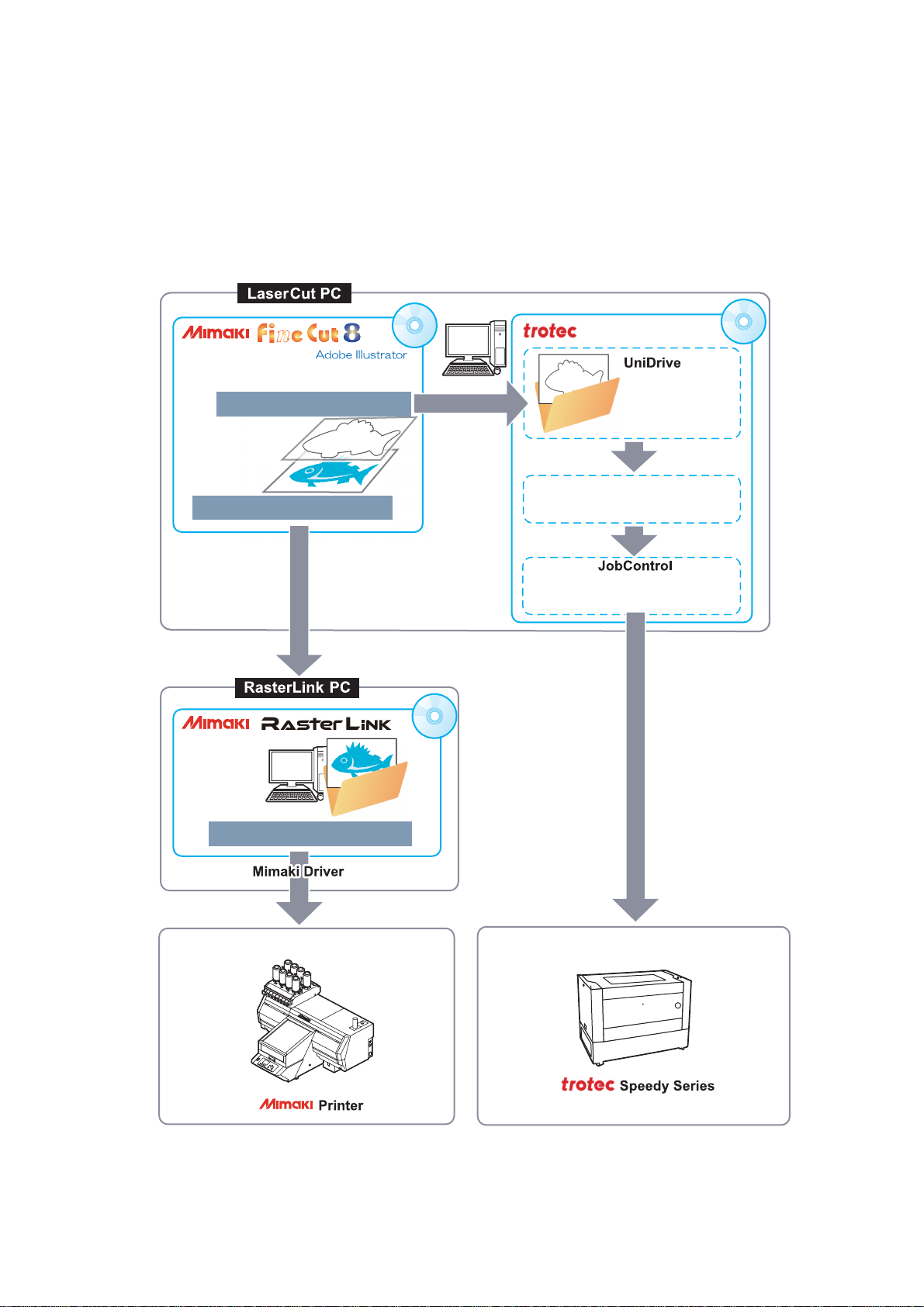
The cut data is transmitted from FineCut to Trotec JobControl and then laser cutting is performed by the Trotec Speedy Laser Engravers (100/300/360/400).
This document covers the basic procedure for using FineCut 8 and RasterLink to print with a printer manufactured by MIMAKI ENGINEERING CO., LTD. (hereinafter referred to as a "Mimaki printer") and carry out laser
cutting with the Trotec Speedy Laser Engraver. The following example shows the case when the FineCut and
Trotec software is installed on the LaserCut PC and the RasterLink software is installed on the RasterLink PC.
• Trotec Laser Cut procedure (when laser cutting is performed automatically according to output from FineCut).
*1. FineCut is compatible with Trotec Speedy Laser Engravers 100/300/360/400 laser engraving ma-
chines.
- 3 -
Page 4
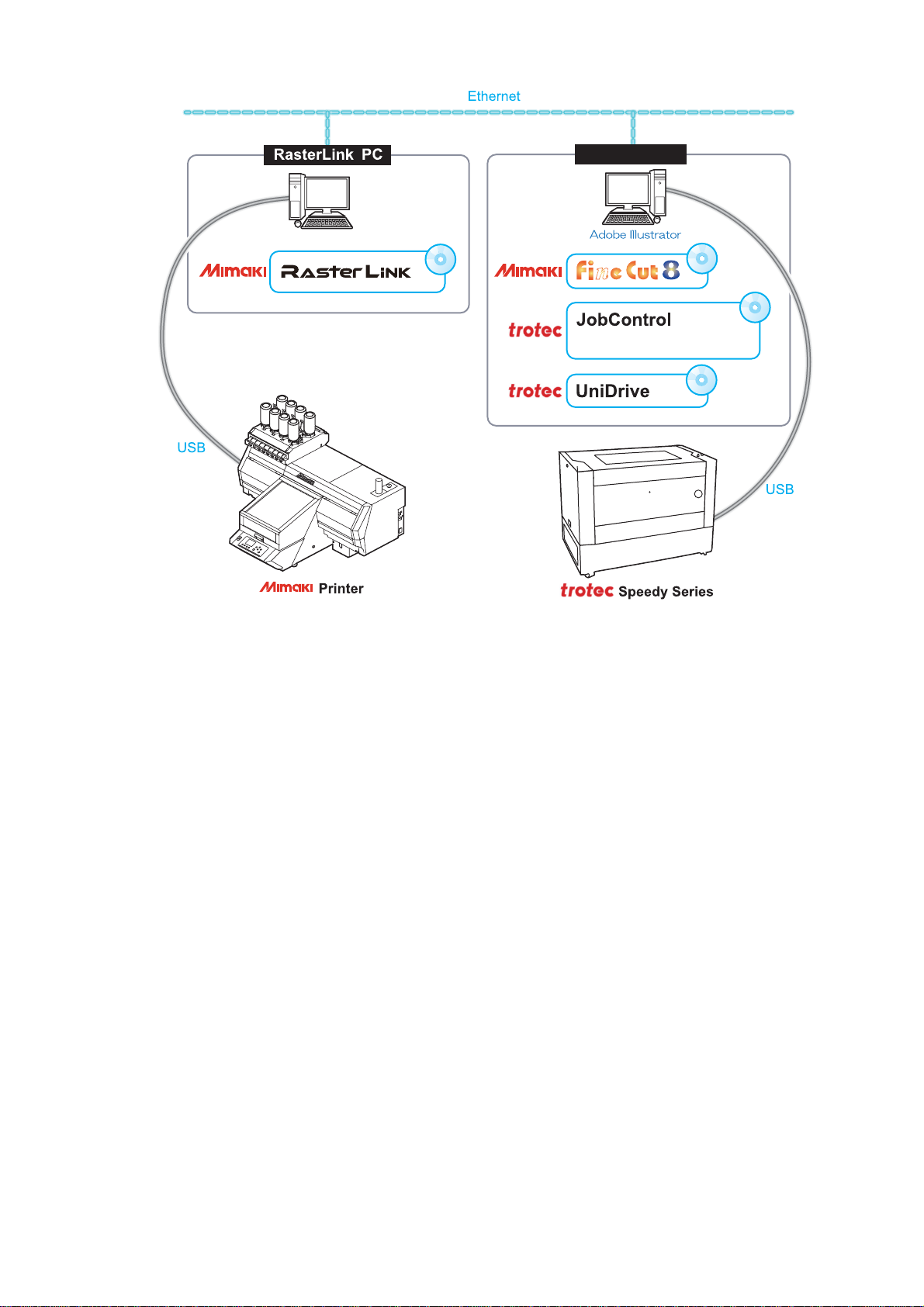
• System configuration
Engraver(PrinterDriver)
LaserCut PC
100/300/360/400
- 4 -
Page 5

Laser cutting preparation procedure
1. Installing the Mimaki software/driver (P.8)
6. Prepare the Mimaki printer for printing (P.15)
5. Prepare the Trotec Speedy Laser Engraver for laser cutting (P.15)
Preparation (P.7)
2. Configure FineCut (P.8)
4. Configure the Trotec software (P.9)
3. Installing the Trotec software/driver (P.9)
1. Install FineCut 8 on the LaserCut PC. (P.8)
2. Install RasterLink on the RasterLink PC. (P.8)
1. Select the Trotec Speedy Laser Engraver in [Model]. (P.8)
2. Open the Trotec color swatch. (P.8)
1. Install Trotec Job Control on the LaserCut PC. (P.9)
2. Install Trotec UniDrive on the LaserCut PC. (P.9)
1. Set the cutting conditions (Trotec JobControl) (P.10)
2. Create a cutting conditions parameter file
*1.
(Trotec UniDrive) (P. 11)
3. Associate the conversion folder
*2
with the cutting conditions parameter file.
(Trotec UniDrive) (P. 13)
Please refer to the Trotec Speedy Laser Engraver operation manual.
Please refer to the "Operation Manual" on the CD bundled with the Mimaki printer.
*1. Cutting conditions parameter file: A file that contains material templates and output conditions.
*2. Conversion folder: When a graphic file is placed in the conversion folder, it is automatically converted into a file for-
mat that is compatible with laser processing and then sent to Trotec JobControl. (When cut data
is output from FineCut to the conversion folder, it is automatically loaded into Trotec JobControl.)
- 5 -
Page 6

Laser cutting output procedure
1. Create the data (P.16)
3. Laser cutting using the Trotec Speedy Laser Engraver (100/300/360/400)
Printing and cutting (P.16)
1. Create the data using Adobe Illustrator (P.16)
• Create the print data, cut data, and alignment frame
*1
data.
1. Set the media. (P. 21)
2. Output from FineCut to the Trotec Speedy Laser Engraver. (P. 21)
2. Printing (P.17)
1. Printing the alignment frame data on paper media (P.17)
2. Printing the print data on media (P.19)
*1. Alignment frame: This is a frame that acts as a reference to prevent shifting during printing and cutting. All data must
be created so that it fits within this frame.
- 6 -
Page 7

Preparation
Before starting laser cutting, it is necessary to install and configure each piece of software and prepare the
printer and Trotec Speedy Laser Engravers (100/300/360/400).
Please proceed to "Printing and cutting" (P.16) if this preparation has already been completed.
The following software applications are required for laser cutting.
Type
Mimaki
software
Trotec
software
Trotec
driver
Trotec
software
Software/
driver
FineCut8
(Ver8.7 or later*1)
Trotec JobControl
Trotec Engraver
Trotec UniDrive
Outline
This is the Adobe Illustrator plug-in cutting software.
The [Output to TrotecLaser] function only works with Adobe Illustrator
CC-CC2017 (Win/Mac). FineCut Trotec Speedy Laser Engravers functions cannot be used in the case of versions prior to Adobe Illustrator
CC.
For the installation procedure, please refer FineCut Reference Guide
“Chapter 1. Installation of FineCut”.
Trotec JobControl is a software application that registers material templates, positions cut data, outputs cut data, etc. (Supplied with the Trotec
Speedy Laser Engravers: CD)
Please refer to the Trotec JobControl operation manual for the installation method.
This is the driver for the Trotec laser plotter that is installed along with
the JobControl software.
Trotec UniDrive is a software application that creates cutting conditions
parameter files and associates the conversion folder with cutting conditions parameters, etc.
Please refer to the Trotec UniDrive Operation Manual for the installation
method.
*1.When using a version earlier than the specified version, download the installer for the upgraded version from the
Mimaki website (http://mimaki.com/
).
• The following software/drivers are required in order to print with a Mimaki printer.
Type
Software/
driver
Outline
This software application is used to receive image data, edit data with
various functions, and send plot data to a Mimaki printer. (Supplied with
Mimaki
software
RasterLink
the Mimaki printer: CD)
Please refer to RasterLink installation guide bundled with the Mimaki
printer for the installation method.
This is the device driver to use the Mimaki inkjet printer / cutting plotter.
Mimaki
driver
Mimaki driver
(Supplied with the Mimaki printer: CD)
*1
Please refer to Mimaki Driver Installation Guide bundled with the
Mimaki printer for the installation method.
*1.This is required for printing with the Mimaki printer.
- 7 -
Page 8
1. Installing the Mimaki software/driver
1. Install FineCut 8 on the LaserCut PC.
• For more details, please refer FineCut Reference Guide “Chapter 1. Installation of FineCut”.
2. Install RasterLink on the RasterLink PC.
• For more details, please refer to RasterLink Installation Guide bundled with the Mimaki printer.
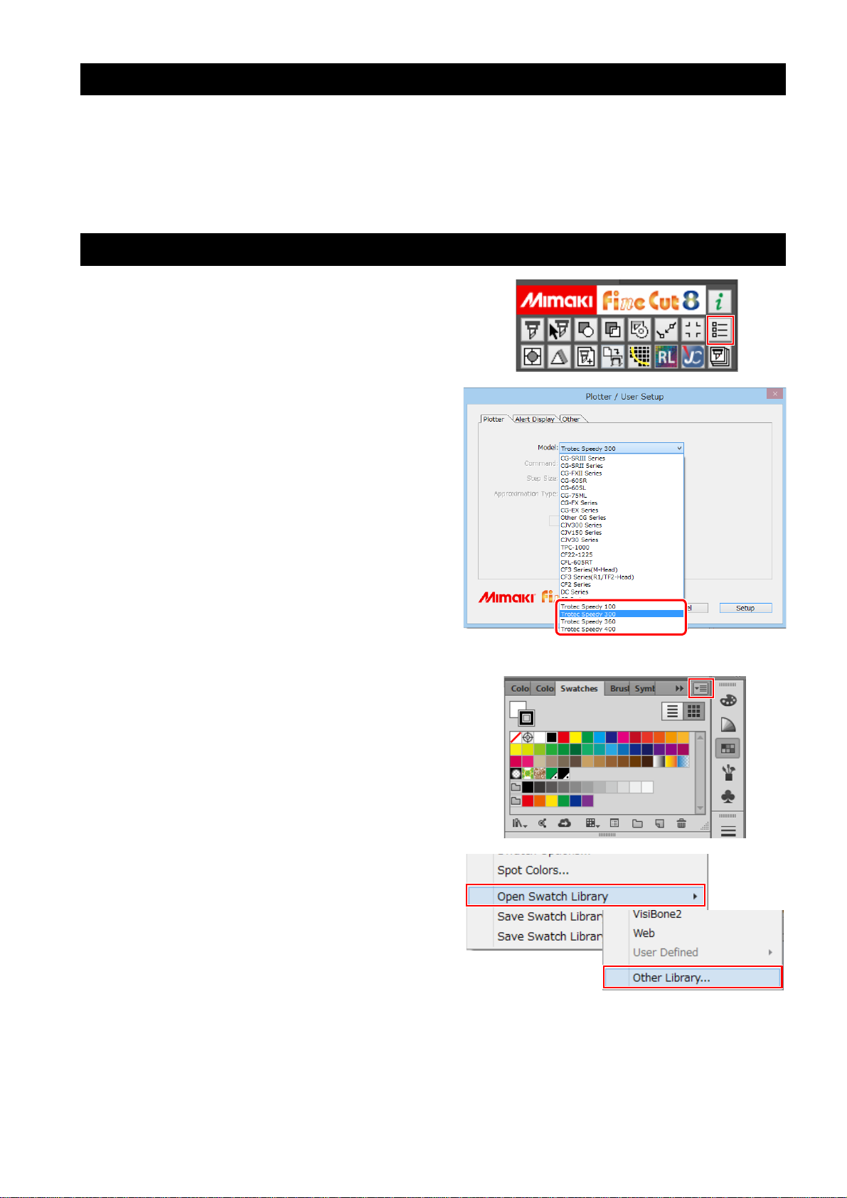
2. Configure FineCut
1. Click the [Plotter/User Setup] button on
the FineCut menu.
2. Select the Trotec Speedy Laser Engraver
in [Model].
Trotec Speedy Laser Engravers are not displayed
in the case of versions earlier than Adobe Illustrator CC.
The following Trotec Speedy Laser Engravers are
compatible.
• Trotec Speedy 100
• Trotec Speedy 300
• Trotec Speedy 360
• Trotec Speedy 400
3. Open the Trotec color swatch.
(1) Click the top right icon on the Adobe Illustrator
swatch window.
(2) Click [Open Swatch Library] - [Other Library].
- 8 -
Page 9
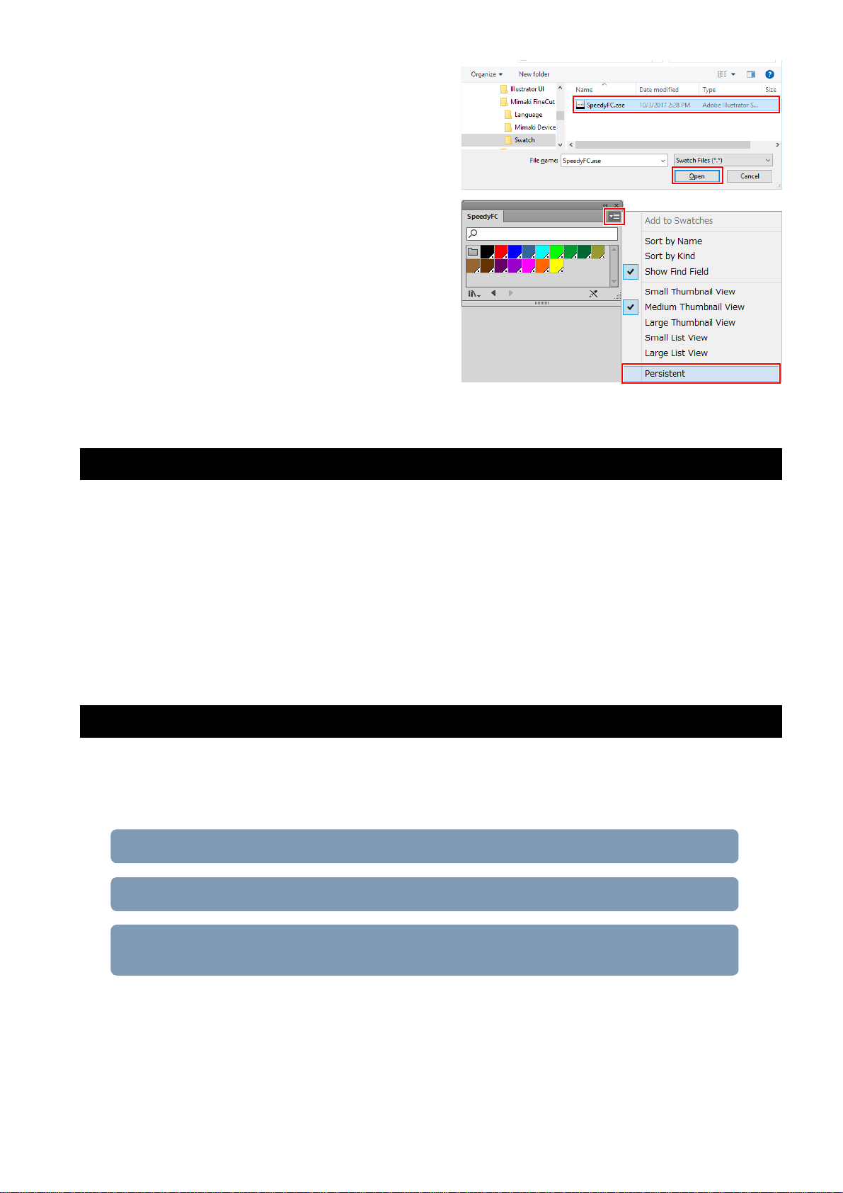
(3) Select "SpeedyFC.ase" in "[Adobe Illustrator
1. Set the cutting conditions (Trotec JobControl) (P.10)
2. Creating a cutting conditions parameter file (Trotec UniDrive ) (P.11)
3. Associate the conversion folder with the cutting conditions parameter file (Trotec UniDrive) (P.13)
plug-in folder]\Mimaki FineCut\Swatch” and
then click [Open].
• The Trotec Color “SpeedyFC” color swatch is
then displayed.
(4) Select [Persistent] from the menu on the upper
right of the displayed color swatch.
• The Trotec color swatch will automatically
come up each time Adobe Illustrator is
launched.
3. Installing the Trotec software/driver
1. Connect the Trotec Speedy Laser Engraver to the LaserCut PC via a USB cable.
2. Turn on the power to the Trotec Speedy Laser Engraver.
3. Install Trotec Job Control on the LaserCut PC.
• Trotec Engraver will also be installed at the same time.
• For more details, please refer to the Trotec JobControl operation manual.
4. Install Trotec UniDrive on the LaserCut PC.
• For more details, please refer to the Trotec UniDrive operation manual.
4. Configure the Trotec software
Create a conversion folder to be designated as the laser cut data output destination for Fine Cut. All data contained within the conversion folder is automatically sent to Trotec JobControl.
• Conversion folder creation procedure
- 9 -
Page 10
Set the cutting conditions (Trotec JobControl)
1. Launch Trotec JobControl.
2. Select [Material Template Setup] on the [Settings] menu.
• The [Material database] dialog is displayed.
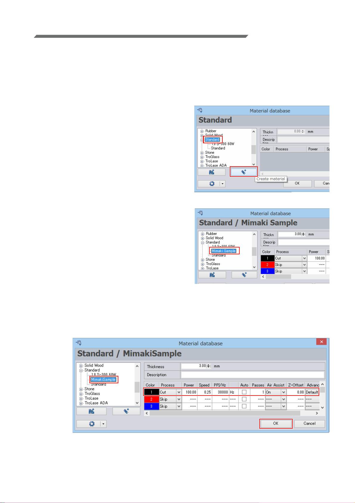
3. Register the new material.
• Register the material template and set the laser cutting conditions for the new material.
• Basic materials have already been registered.
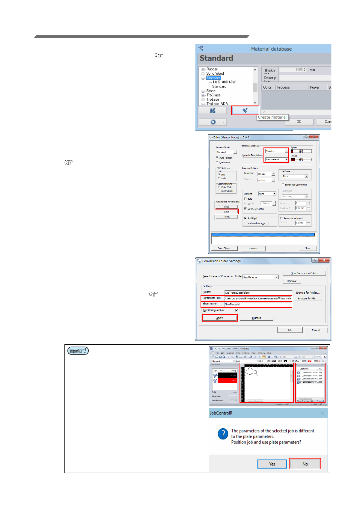
(1) Select [Standard] in the material list on the left
side and then click the [Create material] button.
• The new material is then added to the material list.
(2) The new material can now be given the
desired name.
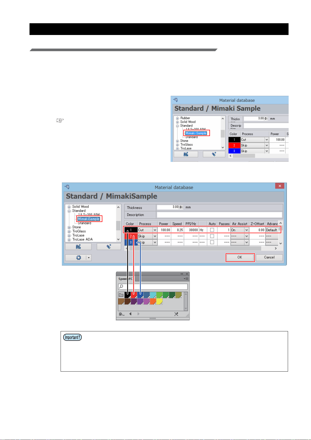
(3) Set the cutting conditions.
• For the example in this document, please set the following conditions.
[Color]: 1 (Black)
[Process]: Cut
[Power] and after: The numerical values suitable for cutting the media.
(4) Click [OK].
- 10 -
Page 11

Creating a cutting conditions parameter file (Trotec UniDrive )
Trotec JobControl
Trotec UniDrive
1. Launch Trotec UniDrive.
• The Trotec UniDrive icon is displayed in the task
tray to the right of the Windows taskbar.
2. Right-click the Trotec UniDrive icon displayed in the task tray to the right of the
taskbar.
• The Trotec UniDrive menu will come up.
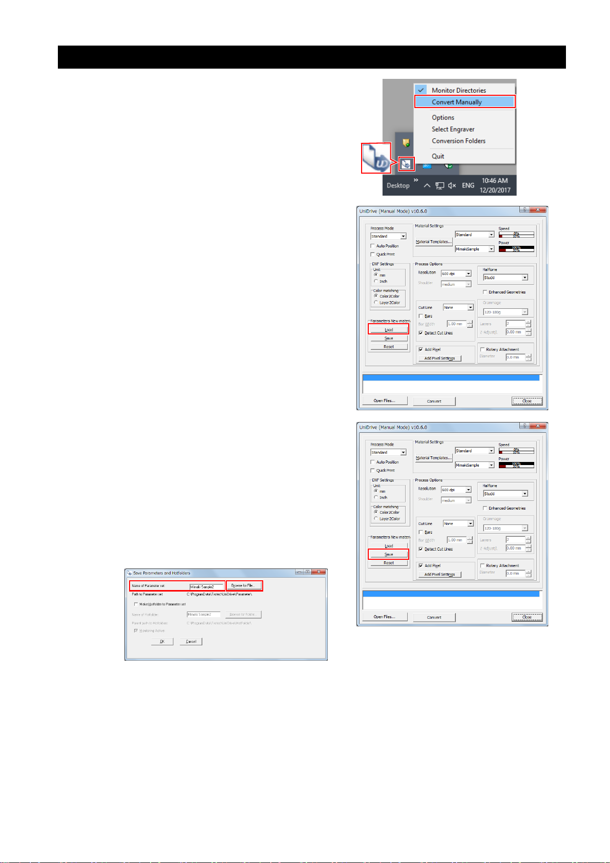
3. Select the [Convert Manually] menu
option.
• The [UniDrive (Manual Mode)] dialog is displayed.
4. Create a cutting conditions parameter
file.
• Associate the material template (laser cutting
conditions) that was set using Trotec Job Control
with the parameter file.
(1) Select the material.
• Please select the material created using Tro-
tec JobControl. ( P.10 "Register the new
material.")
In the upper drop-down list, select the material group. In the lower drop-down list, select
the material template.
(2) Check or uncheck the [Auto Position] check
box.
• For the example in this document, please
check this box.
- 11 -
Page 12
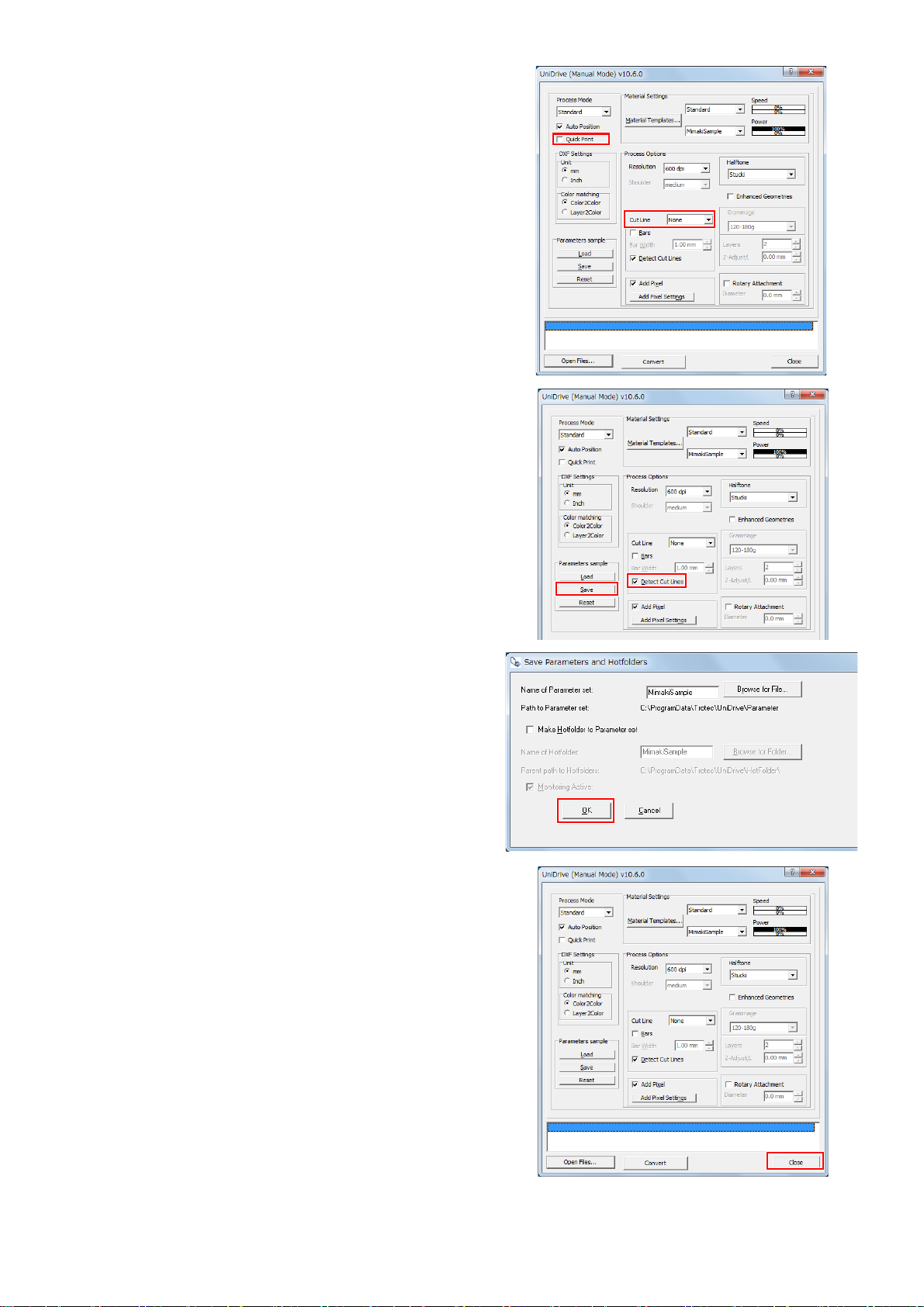
(3) Check or uncheck the [Quick Print] check box.
(3)
(4)
(6)
(5)
• For the example in this document, please
check this box.
• When cut data is sent to Trotec JobControl,
data is automatically output to the Trotec
Speedy Laser Engraver and cutting is performed.
(4) Set [Cut Line] to [None].
(5) Check the [Detect Cut Lines] check box.
(Required)
(6) Click the [Save] button.
• The [Save Parameters and Hotfolders] dialog is displayed.
(7) Click the [OK] button on the [Save Parameters
and Hotfolders] dialog.
• The parameter file will then be saved as the
[Name of Parameter set].
(8) Click the [Close] button on the [UniDrive
(Manual Mode)] dialog.
- 12 -
Page 13
Associate the conversion folder with the cutting conditions parameter file (Trotec UniDrive)
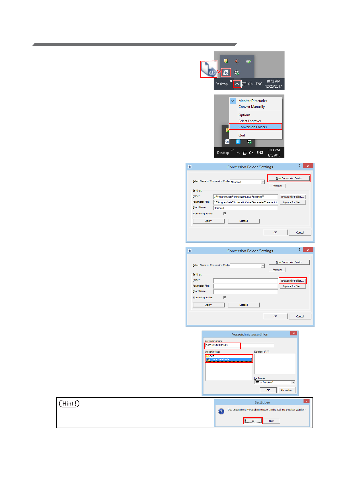
1. Right-click the Trotec UniDrive icon displayed in the task tray to the right of the
taskbar.
• The Trotec UniDrive menu will come up.
2. Select [Conversion Folders].
• The [Conversion Folders Settings] dialog is displayed.
3. Click the [New Conversion Folder] button.
• Register the new folder as a conversion folder in
Trotec UniDrive.
4. Click [Browse for Folder...] next to
[Folder] to set the conversion folder.
• The dialog to select the folder is displayed.
5. Enter the folder path for the conversion
folder.
• For the example in this document, enter "C:\TrotecDataFolder" as the folder name and click [OK].
• This folder is then set as the conversion folder.
Any data present within this folder is automatically sent to Trotec JobControl.
• It is also possible to select folders that were created using Windows Explorer in advance.
• If the folder does not exist, a message asking if
you would like to create a new folder comes up.
Click the [Ja] button.
- 13 -
Page 14

6. The conversion folder name is displayed
in [Short Name].
• This is the name shown in the [Select Name of
Conversion Folder] list. It is possible to change
this name.
7. Click the [Browse for File...] button to the
right of [Parameter File].
• Select the conversion folder loading conditions
(parameter file).
• The dialog to select the parameter file is displayed.
8. Select the cutting conditions parameter
file saved in "Creating a cutting conditions
parameter file (Trotec UniDrive )" (P.11)
and click [Open].
9. Confirm that the [Monitoring Active] check
box is checked and then click the [Apply]
button.
• When the same name as the [Short name] is displayed in [Select Name of Conversion Folder],
registration of the conversion folder is complete.
10. Click the [OK] button.
- 14 -
Page 15

5. Prepare the Trotec Speedy Laser Engraver for laser cutting
Please refer to the Trotec Speedy Laser Engraver operation manual.
6. Prepare the Mimaki printer for printing
Please refer to the "Operation Manual" on the CD bundled with the Mimaki printer.
- 15 -
Page 16
Printing and cutting
1. Create the data
• Be sure to confirm "Preparation" on pages P. 7 to P. 15 before starting printing and laser cut-
ting.
Create the data using Adobe Illustrator
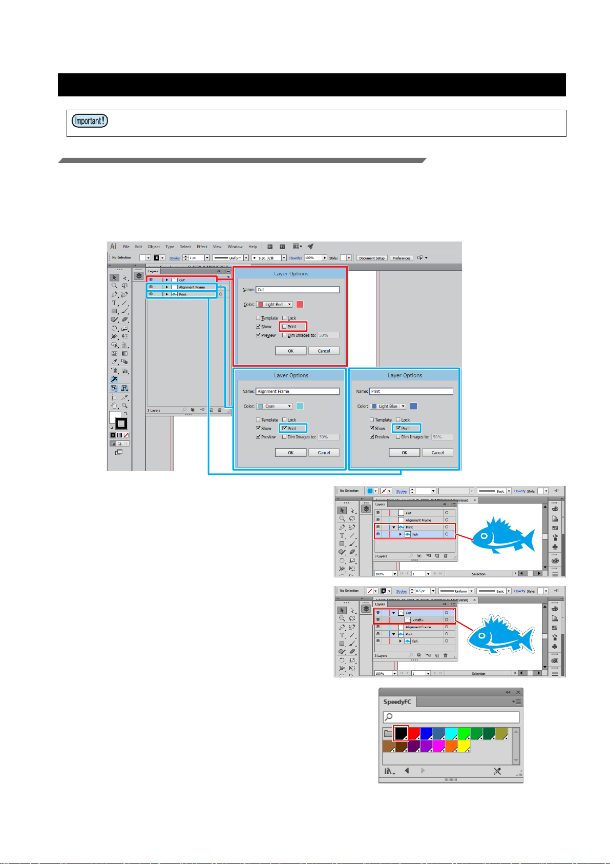
1. Create the print layer, cut layer and alignment frame layer.
• To ensure a smooth output, create the print, cut, and alignment frame layers in Adobe Illustrator in
advance. The alignment frame acts as a reference to prevent shifting during printing and cutting.
• In the [Layer Options] dialogs for each layer, check the [Print] check boxes for the print and alignment
frame layers and uncheck the [Print] check box for the cut layer.
2. Create the print data for the print layer.
3. Create the cut data for the cut layer.
• It is also possible to create a cut line(s) using the
FineCut "Frame Extraction" function.
4. Select the line color for the cut data from
the Trotec color swatch.
• For the example in this document, please select
[FCLaser_Black].
- 16 -
Page 17

• Be sure to set the color in the cut layer data to one that is in the Trotec color swatch.
Data that has a line color that is not a Trotec color cannot be used for laser cutting.
• Data is output in the [Color] order of the material template set with Trotec JobControl.
(P.6 “Register the material database”)
• When there are multiple items of the same TrotecColor data, the data is cut in order
starting with the lowest layer.
5. Create frame data for the alignment
frame layer.
• Using Adobe Illustrator's rectangular tool, create
a frame for the alignment of print and cut data.
Please create it so that all data fits within the
frame and there is a line width of at least 0.2 mm.
2. Printing
Printing the alignment frame data on paper media
1. Output alignment frame data to the RasterLink hot folder.
(1) Click the [Output to RasterLink] button on the
FineCut menu.
(2) Set it to print/cut on the [Layer] tab.
• Set Print to ON only for the alignment frame
layer.
Print Cut Layer
--
ON -
--
(3) Click the [Select Folder] button.
• Select the RasterLink hot folder for the
Mimaki printer to be used.
• If the hot folder has not been created, please
register the Mimaki printer with RasterLink.
(Hot folders are created when the printer is
registered with RasterLink.)
• Folders created using the hot
folder selection dialog will not
function as a hot folder. Be sure to
create the hot folder using RasterLink.
Cut
Alignment frame
Print
- 17 -
Page 18
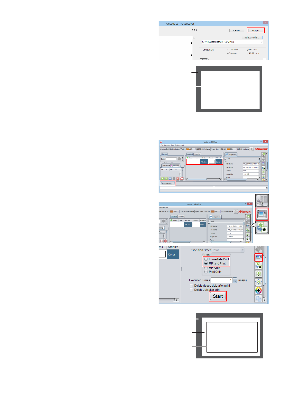
(4) Click the [Output] button.
Printer surface
Paper
Printer surface
Paper
Alignment frame
• The alignment frame print data is sent to the
hot folder of RasterLink.
2. Set the paper media into the Mimaki
printer.
(1) Set the paper media on which you wish to
print the alignment frame onto the Mimaki
printer surface.
• Secure it with tape so that it stays in place.
(2) Set the Mimaki printer to REMOTE mode.
3. Print the alignment frame onto the paper media.
• For the printing method, please refer to the "Operation Manual" on the CD bundled with the Mimaki
printer.
(1) Launch RasterLink.
(2) Click the Mimaki printer tab.
• Alignment frame data is automatically loaded
and then added to the [Job List].
(3) Click the [Execution] icon in the [Function
Icon] list to the right of the screen.
• The [Execution] panel is displayed.
(4) Select [RIP and Print] or [Immediate Print] on
the [Execution] panel and click the [Start] button.
• Printing will start.
(5) The alignment frame is printed.
- 18 -
Page 19

Printing the print data on media
Printer surface
Paper
Alignment frame
Media
Lower right corner of the alignment frame
1. Output print data to the RasterLink hot folder.
(1) Click the [Output to RasterLink] button on the
FineCut menu.
(2) Set it to print/cut on the [Layer] tab.
• Set Cut to ON for the cut and alignment
frame layers, and set Print to ON for the print
layer.
Print Cut Layer
-ON
-ON
ON -
(3) Click the [Select Folder] button.
• Select the RasterLink hot folder for the
Mimaki printer to be used.
• If the hot folder has not been created, please
register the Mimaki printer with RasterLink.
(Hot folders are created when the printer is
registered with RasterLink.)
Cut
Alignment frame
Print
• Folders created using the hot
folder selection dialog will not
function as a hot folder. Be sure to
create the hot folder using RasterLink.
(4) Click the [Output] button.
• The print data is sent to the hot folder of RasterLink.
2. Set the media into the Mimaki printer.
(1) Set the media so that it is aligned with the
lower right corner of the alignment frame on
the Mimaki printer surface.
• Please set the media so that it stays lined up
with the alignment frame. If it is set at an
angle, printing and cutting will become misaligned.
(2) Set the Mimaki printer to REMOTE mode.
- 19 -
Page 20

3. Print the print data into the media.
• For more details regarding the printing method, please refer to the "Operation Manual" on the CD bundled with the Mimaki printer.
(1) Launch RasterLink.
(2) Click the Mimaki printer tab.
• Print data is automatically loaded and then
added to the [Job List].
(3) Click the [General Print] icon in the [Function
Icon] list to the right of the screen.
• The [Image Edit] panel is displayed.
(4) Rotate by 180 .
• Since the origin of the Mimaki printer is in the
lower right corner and the origin of the Trotec
Speedy Laser Engraver is in the upper left
corner, it is necessary to rotate by 180
before printing.
(5) Click the [Execution] icon in the [Function
Icon] list to the right of the screen.
• The [Execution] panel is displayed.
(6) Select [RIP and Print] or [Immediate Print] on
the [Execution] panel and click the [Start] button.
• Printing starts.
(7) The print data is printed.
- 20 -
Page 21

3. Laser cutting using the Trotec Speedy Laser Engraver (100/300/360/400)
For more details, please refer to the Trotec Speedy Laser Engraver operation manual.
Laser cutting
1. Set the printed media on the Trotec
Speedy Laser Engraver.
• Rotate the printed media by 180 and set it so
that it is aligned with the upper left corner of the
laser cutter surface.
2. Adjust the height.
3. Click the [Output to TrotecLaser] button
on the FineCut menu.
• In the case of versions earlier than Adobe Illustrator CC, the [Output to TrotecLaser] button is
not displayed as Trotec Speedy Laser Engravers
are not compatible with these versions.
4. Set the laser output folder.
(1) Click the [Select Folder] button.
(2) Select the conversion folder set with Trotec
UniDrive. ( P.13 "Associate the conversion
folder with the cutting conditions parameter
file (Trotec UniDrive)")
• For the example used in this document,
please select [C:\TrotecDataFolder].
5. Set it to print/cut on the [Layer] tab.
• Set Cut to ON for the cut layer, and set Print to
ON for the alignment frame and print layers.
Print Cut Layer
-ON
ON -
ON -
Cut
Alignment frame
Print
6. Click the [Output] button.
• Be sure to do this while Trotec JobControl and
Trotec UniDrive are running.
- 21 -
Page 22

7. The cut data is automatically loaded by
Trotec Job Control and then laser cutting is performed.
- 22 -
Page 23

Troubleshooting
No
Yes
No
Yes
No
Yes
No
Yes
No
Yes
Troubleshooting procedure
The [Output to TrotecLaser] icon is not displayed
on the FineCut menu.
Are you using Adobe Illustrator CCCC2017 (Win/Mac)?
Please install FineCut on Adobe Illustrator
CC-CC2017 (Win/Mac).
Are you using FineCut ver8.7.0 or later? Please install FineCut ver8.7.0 or later.
Please contact our call center.
Even after cut data is output from FineCut to
TrotecLaser, it is not automatically loaded into Trotec
JobControl.
Is Trotec UniDrive running? Please launch Trotec UniDrive.
Is the conversion folder set in Trotec UniDrive's [Conversion Folders Settings] the
same as the [Laser Output Folder] set on
FineCut's [Output to TrotecLaser] screen?
Please make sure it is the same folder.
( P.13 "Enter the folder path for the conversion folder.", P.21 "Set the laser out-
put folder.")
Please contact our call center.
After cut data is output from FineCut to TrotecLaser
and it is automatically loaded into Trotec JobControl,
the [Automatic cutline needs Red to be defined as cut
color!] message is displayed.
Is this message displayed every time?
In the Trotec JobControl [Material database] dialog, please set the red [Process]
to [Cut].
There is no problem if this is the first time it
has been displayed.
- 23 -
Page 24

Laser cutting does not start even after the data loaded
No
YesNoYesNoYesNoYesNoYesNoYes
to Trotec JobControl is output.
Is the line color of the cut data in Adobe
Illustrator one of the colors in the Trotec
color swatch (FCLaser_
****
)?
Are the correct laser cutting conditions set
for the line color of the cut data in the Trotec JobControl material template?
Is the [No response from engraver...] message displayed?
Is the LaserCut PC connected to the Trotec Speedy Laser Engravers via a USB
cable?
Is the Trotec Speedy Laser Engravers
power turned on?
Select the line color for the cut data from one
of the 16 colors in the Trotec color swatch.
( P.16 "Select the line color for the cut
data from the Trotec color swatch.")
In the Trotec JobControl [Material database]
dialog, please set the cut data line color [Process] to [Cut], and set the correct laser cutting conditions.
Please contact Trotec Laser GmbH.
Connect them using a USB cable.
Turn on the power to the Trotec Speedy
Laser Engravers.
In [View devices and printers] on the Control Panel, is the [USB-Serial Converter?]
device operating correctly?
(If this is not operating correctly, an excla-
mation mark is displayed on the [USBSerial Converter?] icon.)
Please contact Trotec Laser GmbH.
Insert the Trotec JobControl CD in the PC
and update the device.
Be sure to perform this update while the Trotec Speedy Laser Engravers (powered on) is
connected.
- 24 -
Page 25

Laser cutting does not start under the set cutting
No
Yes
No
YesNoYes
conditions.
Have the correct cutting conditions for the
material template been set with Trotec
JobControl?
Is the material template set by Trotec JobControl specified in the parameter file?
Has the parameter file set in Trotec UniDrive [UniDrive (Manual Mode)] been set as
the parameter file in Trotec UniDrive [Conversion Folders Settings]?
Please contact our call center.
Please set the correct cutting conditions in
the material template in the Trotec JobControl [Material database] dialog.
( P.10 "Set the cutting conditions.")
Please set the correct material template in
the Trotec UniDrive [UniDrive (Manual
Mode)] dialog.
( P.31 "Checking/modifying the conversion folder loading conditions")
Please set the correct parameter file.
( P.11 "Creating a cutting conditions
parameter file (Trotec UniDrive )",
P. 1 3
"Associate the conversion folder with the cutting conditions parameter file (Trotec UniDrive)")
- 25 -
Page 26

Using the laser cutter without printing
This section covers the case where the [Quick Print] check box is checked on the Trotec UniDrive [UniDrive
(Manual Mode)] dialog. ( P.12 "Check or uncheck the [Quick Print] check box.")
1. Create a cut layer using Adobe Illustrator
• Uncheck the [Print] check box.
2. Create the cut data.
3. Select the line color for the cut data from
the Trotec color swatch.
4. Set the media on the Trotec Speedy
Laser Engravers.
• Set it so that it is aligned with the upper left corner of the laser cutter surface.
5. Adjust the height.
• For more details, please refer to the Trotec
Speedy Laser Engraver operation manual.
6. Click the [Output to TrotecLaser] button
on the FineCut menu.
- 26 -
Page 27

7. Set the laser output folder.
• Select the conversion folder set with Trotec UniDrive. ( P.13 "Associate the conversion folder
with the cutting conditions parameter file (Trotec
UniDrive)")
8. On the [Layer] tab, make sure that the
cut mark is displayed on the cut layer.
9. Click the [Output] button.
10. The cut data is automatically loaded by
Trotec Job Control and then laser cutting
is performed.
- 27 -
Page 28
Perform cutting under different cutting conditions
Trotec color swatch in
Adobe Illustrator
The 16 colors shown in Trotec JobControl
correspond to the 16 colors of the Trotec color swatch used in Adobe Illustrator. All line
segments with colors set using the Trotec
color swatch in Adobe Illustrator are recognized as laser cut paths. Laser cutting conditions can be set for each color in the Trotec
JobControl [Material database].
Modifying cutting conditions
With the following method, modified cutting conditions are applied to both the newly transmitted data from FineCut and the data already loaded in Trotec JobControl.
1. Launch Trotec JobControl.
2. Select [Material Template Setup] on the [Settings] menu.
• The [Material database] dialog is displayed.
3. Select the material template you wish to
modify from the list of materials on the left
side of the [Material database] screen.
( P.10 "Register the new material.")
4. Click the [OK] button after modifying the cutting conditions.
• Line segments that use colors that have [Process] set to [Skip] in the Trotec JobControl [Material database] will be ignored by JobControl and will not be laser cut. If you
wish for such line segments to be laser cut, in JobControl, specify [Cut] as the [Process] of the [Color] you are using, and then set the cutting conditions.
• The numbers shown over the colors on the Trotec JobControl [Material database]
indicate the cutting order.
- 28 -
Page 29
Adding cutting conditions
View
Job list
1. Create a new material in the Trotec JobControl [Material database]. ( P.10
"Register the new material.")
• The newly created material template also applies
to data already loaded in Trotec JobControl.
2. In the Trotec UniDrive [Convert Manually]
- [UniDrive (Manual Mode)] dialog, create
a parameter file for the new material.
( P.11 "Create a cutting conditions
parameter file.")
3. In the Trotec UniDrive [Conversion Folders] - [Conversion Folders Settings] dialog, create a new conversion folder by
setting the parameter file of the new
material created in step 2. ( P.13
"Associate the conversion folder with the
cutting conditions parameter file (Trotec
UniDrive)")
• If data that has an existing material
template is on the Trotec JobControl
view, it is not possible to reposition this
data by applying a different material
template.
If the message shown on the bottom
right appears, click the [No] button.
Delete the data on the JobControl view,
or drag and drop it back into the job list
on the right side of the screen. It is then
possible to reposition the data with the
new material template applied.
- 29 -
Page 30

Modifying the cutting order
The following two methods can be used.
To cut from the lowest layer, change the order
of the layers in Adobe Illustrator.
In the Trotec JobControl [Material database],
check the order of the colors to be cut, and
modify the line color of the cut data in Adobe
Illustrator.
1. Launch Trotec JobControl.
2. Select [Material Template Setup] on the
[Settings] menu.
3. Check the order of the colors on the
[Material database] dialog.
4. In Adobe Illustrator, change the line color
of the cut data according to the cutting
order. ( P.16 "Select the line color for
the cut data from the Trotec color
swatch.")
• Be sure to set the line colors of the cut data in the
Trotec color swatch.
- 30 -
Page 31
Checking/modifying the conversion folder loading conditions
1. Select the Trotec UniDrive [Convert Manually] menu.
• The [UniDrive (Manual Mode)] dialog is displayed.
2. Click the [Load] button.
• The file selection dialog is displayed.
3. Select the parameter file (loading conditions) that you wish to check/modify.
• The contents of the selected parameter file are
displayed in the [UniDrive (Manual Mode)] dialog.
4. Check/modify the loading conditions in
the [UniDrive (Manual Mode)] dialog.
5. If any of the contents are modified, click
the [Save] button to save the parameter
file.
• If the [Material Settings] in the [UniDrive (Manual
Mode)] dialog are modified, the parameter file is
saved as [Name of Parameter Set] in the [Save
Parameters and Hotfolders] dialog. To save the
parameter file under a different name, enter the
desired name in [Name of Parameter Set], or
click [Browse for File...] and select another
parameter file to overwrite.
- 31 -
Page 32

Cutting from the reverse side of the media
To cut the media with the printed facing down, the media must be first flipped vertically or horizontally before cutting.
This does not apply to data that has already been sent to Trotec JobControl. If you wish to flip the media before
cutting, please resend the data from FineCut.
1. Select [Control Panel] - [View devices and printers].
2. Right-click [Trotec Engraver (ver No.)*1]
in [Printers], and then select [Printing
preferences].
*1. (Ver No.) varies depending on the product version.
3. Check the [Process Options] - [Flip vertically] or [Flip horizontal] check box on the
[Print] tab.
4. When the settings are complete, click the
left button in the lower right corner of the
dialog.
• For settings such as [Quick Print] and [Auto
Position] that are also found in Trotec UniDrive,
the Trotec UniDrive setting takes precedence
over the Trotec Engraver setting.
- 32 -
Page 33

Manual positioning of data sent to Trotec JobControl
View
Job list
1. Select the Trotec UniDrive [Convert Manually] menu.
• The [UniDrive (Manual Mode)] dialog is displayed.
2. Uncheck the [Auto Position] check box.
3. Uncheck the [Quick Print] check box.
4. Save the settings in a parameter file.
( P.11 "Create a cutting conditions
parameter file."Step.(6) to (8))
5. Create the cut data using Adobe Illustrator. ( P.16 "Create the data using
Adobe Illustrator"Step.1 to Step.4)
6. Perform [Output to TrotecLaser] in FineCut. ( P.21 "Click the [Output to TrotecLaser] button on the FineCut menu.")
7. Launch Trotec JobControl.
• Cut data is loaded into the job list on the right
side of the screen.
8. Drag and drop items from the job list into
view and position the data.
9. Click the [WYSIWYG on/off] icon.
• The system will enter Cut Line display mode.
10. Change the positioning manually.
- 33 -
Page 34

Automatic positioning of data sent to Trotec JobControl
1. Select the Trotec UniDrive [Convert Manually] menu.
• The [UniDrive (Manual Mode)] dialog is displayed.
2. Check the [Auto Position] check box.
• After the first data is output, the next data can be
automatically positioned in the free area. As this
results in positioning without gaps, it allows
effective use of media when cutting. This function is useful when cutting multiple instances of
data in succession.
3. Save the settings in a parameter file.
( P.11 "Create a cutting conditions
parameter file."Step.(6) to (8))
Changing the origin during Trotec JobControl automatic positioning (Auto Position OFF)
This can be performed when the Trotec UniDrive [UniDrive (Manual Mode)] dialog [Quick Print] check box is
checked, and the [Auto Position] check box is unchecked. ( P.12 "Check or uncheck the [Quick Print] check
box.", P.11 "Check or uncheck the [Auto Position] check box.")
1. Set the positioning origin.
(1) Select [Options] in the Trotec JobControl [Set-
tings] menu.
(2) In the [Options] dialog, click [Process options]
- [Quick Print].
(3) Set the values for [X] and [Y] under [Quick-
Print jobs are processed at position].
• If the [Auto Position] check box is checked,
the [Auto Position] origin takes precedence.
( P.35 "[Position first job] - [X], [Y]: Sets
the origin.")
• If the [Auto Position] check box is
unchecked, cutting is carried out from the
same origin each time.
- 34 -
Page 35

Changing the origin during Trotec JobControl automatic positioning (Auto Position ON)
The data sent from FineCut to Trotec JobControl is automatically positioned without entering the job list. Automatically positioned data can also be manually moved to the desired place.
This can be performed when the Trotec UniDrive [UniDrive (Manual Mode)] dialog [Auto Position] check box is
checked. ( P.11 "Check or uncheck the [Auto Position] check box.")
1. Select [Options] in the Trotec JobControl
[Settings] menu.
2. In the [Options] dialog, click [Process
options] - [Automation].
3. [Position first job] - [X], [Y]: Sets the origin.
4. Check the [Use second job] check box.
• If the [Use second job] check box is unchecked,
it will be automatically positioned in the JobControl view so that it does not overlap.
5. [Position second job] - [X], [Y]: Sets the
origin for the second and subsequent
jobs.
- 35 -
Page 36

Manual output of data sent to Trotec JobControl
1. Select the Trotec UniDrive [Convert Manually] menu.
• The [UniDrive (Manual Mode)] dialog is displayed.
2. Uncheck the [Quick Print] check box.
3. Save the settings in a parameter file.
( P.11 "Create a cutting conditions
parameter file."Step.(6) to Step.(8))
4. Output the cut data from FineCut.
( P.21 "Laser cutting"Step.3 to Step.6)
5. The cut data is automatically loaded by
Trotec Job Control.
6. Click the loaded data to select it.
7. Click the [WYSIWYG on/off] icon.
• The system will enter Cut Line display mode.
8. Set the media on the Trotec Speedy
Laser Engraver.
9. Adjust the height.
- 36 -
Page 37

10. Click the [Start] icon.
• The cut data is output from Trotec JobControl to
the Trotec Speedy Laser Engraver.
11. Laser cutting is started.
- 37 -
Page 38

The printing and cutting processes are misaligned
Please carry out printing after cutting. If there is any misalignment when printing after cutting, please output using
register marks.
Register marks created with Adobe Illustrator or FineCut cannot be used. Only Trotec dedicated register marks
are valid. For more details, please refer to the Trotec JobControl guide.
Printing after cutting
1. Create the cut data. ( P.16 "Create the data using Adobe Illustrator")
2. Check the Trotec UniDrive [Quick Print]
check box.
• P.12 "Check or uncheck the [Quick Print]
check box."
3. Start laser cutting.
(1) Set the media on the Trotec Speedy Laser
Engraver.
• Set the media so that it is aligned with the
upper left corner of the laser cutter surface.
(2) Adjust the height.
(3) Click the [Output to TrotecLaser] button on the
FineCut menu.
(4) Set the laser output folder.
(5) Set it to print/cut on the [Layer] tab.
• Set Cut to ON for the cut layer, and set Print
to ON for the alignment frame layer.
Print Cut Layer
-ONCut
ON - Alignment frame
--Print
- 38 -
Page 39

(6) Click the [Output] button.
Paper
(7) Laser cutting is started.
4. Output the cut data to the RasterLink hot
folder.
(1) Click the [Output to RasterLink] button on the
FineCut menu.
(2) Set it to print/cut on the [Layer] tab.
• Set Print to ON for the cut layer and Cut to
ON for the alignment frame layer.
Print Cut Layer
ON - Cut
- ON Alignment frame
--Print
(3) Click the [Select Folder] button.
• Select the RasterLink hot folder for the
Mimaki printer to be used.
(4) Click the [Output] button.
• The cut line print data is sent to the hot folder
of RasterLink.
5. Print the cut line(s).
(1) Set the paper media on which you wish to
print the cut line(s) onto the Mimaki printer
surface.
(2) Set the Mimaki printer to REMOTE mode.
- 39 -
Page 40

(3) Launch RasterLink.
Printer surface
Paper
Cut line
Printer surface
Media
Paper
(4) Click the Mimaki printer tab.
• The cut line data is automatically loaded and
then added to the [Job List].
(5) Click the [Execution] icon in the [Function
Icon] list to the right of the screen.
• The [Execution] panel is displayed.
(6) Select [RIP and Print] or [Immediate Print] on
the [Execution] panel and click the [Start] button.
• Printing starts.
(7) The cut line(s) are printed.
6. Set the laser cut media so that it is
aligned with the printed cut line(s).
- 40 -
Page 41

7. Output the print data to the RasterLink hot folder.
(1) Click the [Output to RasterLink] button on the
FineCut menu.
(2) Set it to print/cut on the [Layer] tab.
• Set Cut to ON for the alignment frame layer,
and set Print to ON for the print layer.
Print Cut Layer
--Cut
- ON Alignment frame
ON - Print
(3) Select the RasterLink hot folder and click the
[Output] button.
• The print data is sent to the hot folder of RasterLink.
8. Print using the Mimaki printer.
(1) Launch RasterLink.
• Print data is automatically loaded and then
added to the [Job List].
(2) Click the Mimaki printer tab.
(3) Select [RIP and Print] or [Immediate Print] on
the [Execution] panel and click the [Start] button.
• Printing starts.
(4) The Mimaki printer starts printing.
- 41 -
Page 42

D203261-10-26012018
© 2018 MIMAKI ENGINEERING CO., LTD. All rights reserved.
MM
 Loading...