

Page 1
www.troteclaser.com
SP3000
Operation Manual
BA 8034_2.4_EN (12/2016)
ENGLISH
Page 2

2 / 87 BA 8034_2.4_EN (12/2016)
www.troteclaser.com
Trotec Laser GmbH
Linzer Straße 156
A – 4600 Wels
AUSTRIA
Trotec Laser GmbH
Freilingerstraße 99
A – 4614 Marchtrenk
AUSTRIA
Tel.: +43-(0)7242-239-0
trotec@troteclaser.com
www.troteclaser.com
Translated manual
Technical
Changes
Technical specifications are subject to change without notice.
Trotec Laser GmbH reserves the right to improve or modify any of the
products without prior notice.
Copyright
This documentation with all illustrations is intellectual property of
Trotec Laser GmbH. The entire documentation is given to the user for
personal use only. Reproduction, translation or any distribution to third parties
is not permitted without the prior consent of Trotec Laser GmbH. Any breach
of law will be prosecuted.
Page 3

SP3000
Content
BA 8034_2.4_EN (12/2016) 3 / 87
www.troteclaser.com
CONTENT
1 General .............................................................................................................................................. 6
1.1 Information about this manual .................................................................................................... 6
1.1.1 Storage of the manual ...................................................................................................... 6
1.1.2 Complementary documentation ....................................................................................... 6
1.2 Explanation of symbols ............................................................................................................... 7
1.3 Liability and warranty .................................................................................................................. 8
1.4 Scope of delivery (standard configuration) ................................................................................. 9
1.5 Type plate ................................................................................................................................. 10
2 Safety ............................................................................................................................................... 11
2.1 Safety principles ....................................................................................................................... 11
2.1.1 Intended use ................................................................................................................... 11
2.1.2 Improper use .................................................................................................................. 11
2.1.3 Machine modification ...................................................................................................... 12
2.1.4 Operating modes ............................................................................................................ 12
2.1.6 Applicable safety regulations .......................................................................................... 13
2.2 Laser safety .............................................................................................................................. 14
2.2.1 Laser classification ......................................................................................................... 14
2.2.2 Laser and working area .................................................................................................. 16
2.3 Area of responsibility ................................................................................................................ 17
2.3.1 Responsibilities of the operator ...................................................................................... 17
2.3.2 Responsibilities of the operating personnel ................................................................... 18
2.4 Operating and service personnel requirements ....................................................................... 19
2.5 Warning and information labels ................................................................................................ 20
2.6 Safety devices .......................................................................................................................... 22
2.6.1 Overview ......................................................................................................................... 22
2.6.2 Main switch ..................................................................................................................... 23
2.6.3 Key switch ...................................................................................................................... 23
2.6.4 Emergency stop button .................................................................................................. 23
2.6.5 Casing elements, side panel and covers ....................................................................... 23
2.6.6 Warning lamp ................................................................................................................. 23
2.6.7 Bumper and micro switch ............................................................................................... 24
2.6.8 Light curtain .................................................................................................................... 24
2.6.9 Laser deflector shield and hall sensor ............................................................................ 24
2.6.10 Light sensor and reflector ............................................................................................... 24
2.6.11 In case of safety device malfunction .............................................................................. 24
2.7 In case of an emergency .......................................................................................................... 25
2.7.1 In case of malfunction .................................................................................................... 25
2.7.2 In case of accident, First Aid .......................................................................................... 25
2.8 Specific hazards ....................................................................................................................... 26
2.8.1 Fire hazard ..................................................................................................................... 26
2.8.2 Gases, fumes and dust .................................................................................................. 26
2.8.3 Reflecting material .......................................................................................................... 27
2.8.4 Optical components ........................................................................................................ 28
3 EC Declaration of Conformity ....................................................................................................... 30
4 Technical Data ................................................................................................................................ 31
Page 4

SP3000
Content
4 / 87 BA 8034_2.4_EN (12/2016)
www.troteclaser.com
4.1 Data sheet ................................................................................................................................ 31
4.2 Dimensions and weight............................................................................................................. 34
4.2.1 Machine dimensions and weight .................................................................................... 34
4.2.2 Operation panel exterior dimension ............................................................................... 36
4.2.3 Travelling exhaust exterior dimensions .......................................................................... 37
4.2.4 Exhaust with sound-insolating enclosure (optional) ....................................................... 38
4.3 Materials ................................................................................................................................... 39
5 Machine overview ........................................................................................................................... 41
5.1 General overview ...................................................................................................................... 41
5.2 Operating elements .................................................................................................................. 42
5.2.1 Operating elements overview ......................................................................................... 42
5.2.2 Operation panel .............................................................................................................. 43
5.2.3 Compressed air display .................................................................................................. 47
5.2.4 Compressed air regulator ............................................................................................... 47
5.2.5 Key switch ...................................................................................................................... 47
5.2.6 Emergency stop button .................................................................................................. 47
5.2.7 Exhaust segment button ................................................................................................. 48
5.2.8 Max. compressed air / control lamp ............................................................................... 48
5.3 Tables (multifunctional table concept) ...................................................................................... 49
5.3.1 Cutting tables.................................................................................................................. 49
5.4 Lenses ...................................................................................................................................... 51
5.5 Nozzles ..................................................................................................................................... 51
6 Transport, unloading and packaging ........................................................................................... 52
6.1 Safety notes .............................................................................................................................. 52
6.2 Delivery state ............................................................................................................................ 52
6.3 Temperature and humidity ........................................................................................................ 53
6.4 Required tools for unloading and transport .............................................................................. 53
6.5 Relocation of the machine ........................................................................................................ 53
7 Setup and installation .................................................................................................................... 54
7.1 Safety notes .............................................................................................................................. 54
7.2 Operating environment ............................................................................................................. 55
7.2.1 Temperature and humidity ............................................................................................. 55
7.2.2 Subsoil conditions .......................................................................................................... 55
7.2.3 Environmental conditions ............................................................................................... 55
7.3 Setup and installation ............................................................................................................... 55
7.4 Connections .............................................................................................................................. 56
7.4.1 Connecting the mains ..................................................................................................... 56
7.4.2 Operating console connection ........................................................................................ 56
7.4.3 Connecting a Trotec exhaust system ............................................................................. 56
7.4.4 Connecting a Trotec cooling system .............................................................................. 56
8 Operation ......................................................................................................................................... 57
8.1 Before operation ....................................................................................................................... 57
8.2 Software .................................................................................................................................... 57
8.3 Power ON/OFF ......................................................................................................................... 58
8.3.1 Power ON ....................................................................................................................... 58
8.3.2 Power OFF ..................................................................................................................... 60
8.4 Lens placement ........................................................................................................................ 61
Page 5

SP3000
Content
BA 8034_2.4_EN (12/2016) 5 / 87
www.troteclaser.com
8.5 Table placement ....................................................................................................................... 62
8.6 Focusing methods .................................................................................................................... 63
8.6.1 Overview ......................................................................................................................... 63
8.6.2 Focus tool ....................................................................................................................... 64
8.6.3 Software focus ................................................................................................................ 65
8.6.4 Sonar Technology™ ....................................................................................................... 66
9 Maintenance .................................................................................................................................... 67
9.1 Safety notes .............................................................................................................................. 67
9.2 Maintenance schedule .............................................................................................................. 68
9.3 Cleaning the machine ............................................................................................................... 69
9.4 Cleaning the optics ................................................................................................................... 70
9.4.1 Lens design .................................................................................................................... 70
9.4.2 Cleaning the lens ............................................................................................................ 70
9.4.3 Cleaning the laser deflector shield and nozzle ............................................................... 73
9.4.4 Cleaning the protective glas ........................................................................................... 73
9.5 Cleaning the head exhaust ....................................................................................................... 77
9.6 Cleaning the vent slots of the table exhaust ............................................................................. 77
9.7 Cleaning the ultrasonic sensor (Option Sonar Technology™) ................................................. 77
10 Troubleshooting ............................................................................................................................. 78
10.1 Errors, cause and resolutions ................................................................................................... 78
11 Contact details ................................................................................................................................ 81
11.1 Technical Support ..................................................................................................................... 81
11.2 Local Offices / Sales ................................................................................................................. 81
11.3 Technical Documentation ......................................................................................................... 81
12 Disassembly.................................................................................................................................... 82
13 Disposal ........................................................................................................................................... 82
14 Appendix ......................................................................................................................................... 83
14.1 Acceptance form ....................................................................................................................... 83
14.2 Training verification form .......................................................................................................... 84
14.3 Response form ......................................................................................................................... 85
14.4 How to create a service file....................................................................................................... 86
Page 6

SP3000
General
6 / 87 BA 8034_2.4_EN (12/2016)
www.troteclaser.com
1 General
1.1 Information about this manual
PLEASE READ THIS MANUAL CAREFULLY BEFORE USE
KEEP THE MANUAL FOR FURTHER CONSULTATION
This manual describes how to operate the machine properly and safely. Be sure to follow the safety
instructions given here, as well as any local accident prevention regulations and general safety
regulations applicable to the field of usage.
Before beginning any work on the machine, ensure that the manual, in particular the chapter entitled
“Safety Information” and the respective safety guidelines, has been read in its entirety and fully
understood.
1.1.1 Storage of the manual
This manual is an integral part of the machine and must therefore be kept in the direct vicinity of the
machine and be accessible at all times.
1.1.2 Complementary documentation
Complementary documentation can be found on the supplied DVD.
Software Operation Manual
Trotec JobControl®
JobControl_Operationmanual_x.x.x_Vx.x
Pre-installation Guide
SP3000_Preinstallation Guide_EN
Page 7

SP3000
General
BA 8034_2.4_EN (12/2016) 7 / 87
www.troteclaser.com
1.2 Explanation of symbols
Important technical safety notes and instructions in this manual are marked with symbols. These
instructions for workplace safety must be complies with and followed. Here special attention must be
paid in order to avoid accidents, injury to persons or material damage.
DANGER
This symbol indicates information noncompliance wherewith result in death or serious
injury.
WARNING
This symbol indicates information noncompliance wherewith may result in death or
serious injury.
WARNING
This symbol warns of potentially dangerous situations related to electric voltage. Failure to
observe the safety instructions leads to risk of serious injury or death. Care is to be taken
in particular during maintenance and repair work.
WARNING
This symbol warns of potentially dangerous situations related to the laser beam. Failure to
observe the safety instructions leads to risk of serious injury.
Material damage
This symbol indicates information noncompliance wherewith may lead to material
damage, functional failures and/or machine breakdown.
Info
This symbol marks tips and information which are to be observed to ensure efficient and
failure-free operation of the machine.
Page 8

SP3000
General
8 / 87 BA 8034_2.4_EN (12/2016)
www.troteclaser.com
1.3 Liability and warranty
Warranty periods specified in the manufacturers "warranty terms and conditions" shall be binding for
the buyer. If no warranty periods are specified, the general terms and conditions of sale, delivery and
payment apply.
All information, illustrations, tables, specifications and diagrams contained in this operation manual
have been carefully compiled according to the current state of technology. No liability is accepted with
regard to errors, missing information and any resulting damage or consequential loss.
Strict compliance with the safety procedures described in this operation manual and extreme caution
when using the equipment are essential for avoiding and reducing the possibility of personal injury or
damage to the equipment. The manufacturer shall not be liable for any damage and or faults resulting
from non-observance of instructions in this manual.
Non-observance of the operation, maintenance and service instructions described within this manual
absolves Trotec from any liability in case of a defect.
Furthermore, Trotec Laser GmbH shall accept no liability whatsoever for damage caused by the use of
non-original parts and accessories.
Additionally, Trotec Laser GmbH shall not be held responsible for any personal injury or property
damage, of an indirect or specific nature, consequential loss, loss of commercial profits, interruption to
business, or loss of commercial information resulting from use of the equipment described in this
manual.
Any software forming part of this equipment may be used only for the purposes for which it was
supplied by Trotec Laser GmbH. It is strictly prohibited to make any alterations, to prepare
translations, decompile or disassemble the software.
Trotec Laser GmbH reserves the right to update any of the information, illustrations, tables,
specifications and diagrams contained in this operation manual with regard to technical developments
at any time without notice.
Page 9

SP3000
General
BA 8034_2.4_EN (12/2016) 9 / 87
www.troteclaser.com
1.4 Scope of delivery (standard configuration)
1. Laser machine
2. Travelling exhaust
3. Operator console
4. Dell Tower PC for the operator console (according to order)
5. DVD (with laser software, printer driver and operation manuals)
6. Focusing tool(s) (according to lens order)
7. Cleaning kit for optics
8. Nozzles (2 pcs.: ø3 and ø7)
9. Lens: 2.5” (standard) and 3.75”, 5.0" (or according to order)
10. Multifunctional table concept (according to order)
11. Allen key kit
12. Open-end wrench
13. Power cord 5 meter (according to order)
14. USB computer connection cable
15. RS232 cable (according to order)
16. Exhaust connection cable (according to order)
17. Exhaust (according to order)
18. Cooling system (according to order)
19. Compressed air connection "Eurokupplung" (one hand universal quick lock coupling)
The actual scope of delivery may be different, depending on the special model, additional order
options or newest technical changes.
Page 10

SP3000
General
10 / 87 BA 8034_2.4_EN (12/2016)
www.troteclaser.com
1.5 Type plate
The type plate with the CE mark is located close to the main switch on the right hand side of the
machine.
Enter the serial number, model and year of manufacture into your manual and always refer to them
when contacting our representative or service office for enquiries, troubleshooting or ordering of
replacement parts.
Serial number: _____________________________
Model: ___________________________________
Year of manufacture: ________________________
Page 11

SP3000
Safety
BA 8034_2.4_EN (12/2016) 11 / 87
www.troteclaser.com
2 Safety
At the time of the development and production of the machine, it was built in accordance with
recognized technological regulations and is therefore considered operationally safe.
However, hazards may arise if the machine is used improperly, operated by untrained personnel or
employed for purposes other than those it was designed for.
The present chapter provides an overview of all important safety considerations necessary to ensure
safe and trouble-free operation of the machine. Other chapters of this manual contain specific safety
instructions which are marked with symbols in order to avert dangers.
2.1 Safety principles
2.1.1 Intended use
The machine described in this manual is intended exclusively for laser cutting, engraving and
marking of non-metal and material according to the intended use of the machine using the
supplied software.
The system must be operated, maintained and repaired only by trained personnel familiar with the
designated field of use and the dangers of the machine!
Operate the machine only in technically flawless condition and when it fully complies with the EC
Machinery Directive.
For material details see chapter “Materials” or contact your local Trotec salesperson or Trotec
technical support.
The intended use of this machine also includes that all personnel involved in installation, set-up,
operation maintenance and repair of the machine must have read and understood the Operation
Manual and in particular the “Safety” section, and comply with the instructions.
2.1.2 Improper use
Use of the machine for any purposes other than those intended or described in the present manual is
regarded as improper and therefore prohibited.
Trotec will not accept any liability for damage caused by improper use. The risks in case of improper
use are exclusively borne by the user.
Page 12

SP3000
Safety
12 / 87 BA 8034_2.4_EN (12/2016)
www.troteclaser.com
2.1.3 Machine modification
It is strictly prohibited to alter, refit or modify the machine in any way without the express consent of
the manufacturer.
Likewise, it is strictly prohibited to remove, bridge or bypass any safety devices.
Operating conditions and connection and setup values stated in the data sheet must be complied with
at all times.
Operation of the system is permitted only with original parts and accessories by the manufacturer. Use
of third-party parts affects machine safety.
2.1.4 Operating modes
2.1.4.1 Normal operation
For normal operation the following conditions must be met:
Intended use of the machine (see chapter "Intended use")
Operation of the machine only by trained personnel
Full functional and mounted safety devices
Machine must be in technically flawless condition
Only non-metal and material according to the intended use of the machine must be used.
During normal operation it is not necessary to wear safety glasses.
2.1.4.2 Service operation
Service activities may be carried out only by authorized, trained service technicians. If side panels as
well as covers get removed and safety devices get bypassed, it can lead to direct and indirect
scattered radiation.
The service operation is therefore declared as laser class 4 (US: class IV) and proper precautions
need to be taken (see "Laser classification").
Page 13

SP3000
Safety
BA 8034_2.4_EN (12/2016) 13 / 87
www.troteclaser.com
2.1.6 Applicable safety regulations
The following directives and guidelines must be observed to avoid hazards when operating Trotec
laser systems:
EN 60825-1 Safety of Laser Products - Part 1: Equipment Classification and Requirements
EN 60950 Information Technology Equipment – Safety
EN 61010-1 Safety Requirements for Electrical Equipment for Measurement, Control and
Laboratory Use; General Requirements
EN 60204-1 Electrical equipment of machines
BGV B2 Laser Radiation
UL 60950 Standard for Safety for Information Technology Equipment
UL 31011-1 Electrical Equipment for Laboratory Use – Part 1: General
21 CFR 1040.10 Performance Standards for Light-Emitting Products – Specific Laser Products
21 CFR 1040.11 Performance Standards for Light-Emitting Products – Specific-Purpose Laser
Products
The general guidelines and directives listed within this manual may differ according to
locality, region or country.
Therefore, always observe the directives as well as the regulations of the institutions for
statutory accident insurance association applicable to you.
The operator is responsible for fulfilling all safety requirements, as Trotec Laser GmbH
has no influence on the proper use of the machine.
Page 14
SP3000
Safety
14 / 87 BA 8034_2.4_EN (12/2016)
www.troteclaser.com
2.2 Laser safety
2.2.1 Laser classification
The here described machine is equipped with an enclosed laser pointer and a sealed carbon dioxide
laser source that emits invisible and intense laser radiation with a wavelength of 10.6 microns.
Laser classification according to DIN EN 60825-1 "Safety of Laser Products":
- SP3000 laser machine Class 2 (US: Class II) in the working area and operating range,
due to the key safety devices and enclosed laser pointer
(normal operation)
- Laser source Class 4 (US: Class IV)
- Enclosed laser pointer Class 2 (US: Class II)
WARNING
Laser radiation of Class 2 (US: class II)
For Class 2 (US: Class II) laser is short term exposure (up to 0.25 sec) harmless to the eyes
and can therefore be operated without additional protective measures. However it can cause
irritation of the eyes if the natural avoidance reaction (staring into the beam deliberately) or
eyelid closure reflex is suppressed.
- Do not suppress the eyelid closure reflex.
- Do not stare directly into the beam.
- Close eyes, turn away.
- Never look at the laser beam directly with an optical instrument, e.g. a lens.
WARNING
Laser radiation of Class 4 (US: class IV)
Exposure to laser radiation of Class 4 (US: Class IV) can cause injury to the eyes and skin.
- The skin and eyes must not be exposed to direct or reflected or scattered radiation.
- Wear suitable laser safety protection glasses.
- When dealing with Class 4 (US: Class IV) laser machines, it is necessary to appoint a
trained laser safety officer to evaluate potential hazards and to ensure that appropriate
control measures are implemented.
It is the responsibility of the operator to comply with the national official and statutory
regulations for the operation of a class 4 (US: class IV) laser system or laser system with
a build in laser source of class 4 (US: class IV).
Page 15

SP3000
Safety
BA 8034_2.4_EN (12/2016) 15 / 87
www.troteclaser.com
2.2.1.1 Class 2 (US: class II)
The accessible laser radiation of Class 2 (US: Class II) laser systems does not pose any hazard for
the skin. Diffuse reflections as well as any short-term irradiation of the eyes (exposure time
max. 0.25 sec) also pose no risk due to the low output power.
However, it is possible to suppress the natural eyelid closure reflex and stare into the class-2 beam for
a time long enough for the eyes to get injured.
2.2.1.2 Class 4 (US: class IV)
Class 4 (US: class IV) high powered lasers (visible or invisible) considered to present potential acute
hazard to the eye and skin for both direct and scatter (diffused) conditions.
Also have potential hazard considerations for fire (ignition) and byproduct emissions from target or
process materials. It is the responsibility of the operator of the machine to take appropriate
measurements to eliminate any dangers such as fire or explosions through the laser beam.
2.2.1.3 Precautions when dealing with a class 4 (US: class IV) laser machine
When dealing with class 4 (US: class IV) laser machine follow the following precautions:
- According to BGV B2 „Laser Emission“, a competent laser safety officer has to be appointed
in writing to evaluate potential hazards and to ensure that appropriate control measures are
implemented.
- The laser controlled area shall be posted with appropriate warning signs or warning lamps and
the area shall be defined to contain the laser radiation.
- The laser controlled area must be protected against unauthorized access.
- The operator of class 4 (US: class IV) laser systems always has to wear appropriate safety
glasses.
- An indicator (typically a light) to provide a warning of laser emission in advance of and during
the emission time.
Compliance with the points above does not absolve the operator from meeting the relevant standards
and guidelines for the operation of a class 4 (US: class IV) laser system.
Page 16
SP3000
Safety
16 / 87 BA 8034_2.4_EN (12/2016)
www.troteclaser.com
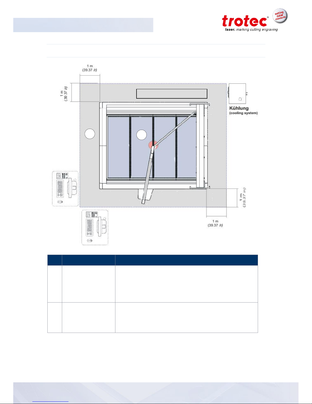
2.2.2 Laser and working area
No
Name
Description
1
Laser area
(working surface /
operating range of
the laser)
The laser area is a defined area in which the value of the
maximum permissible exposure (MPE: 1000W/M²) of laser
radiation may exceed or may leak laser radiation. The laser
area of the SP3000 results from the working surface and the
circular area of approx. ø 5cm (1.97 inch) below the laserhead.
2
Working area of the
operator
The safe working area of laser class 2 (US: class II) results
from the space requirements of the machine and its
components and a distance of 1 meter (39.37 inch). During
normal operation it is not necessary to wear safety glasses.
1
2
Laser Class 2 (US: class II)
Page 17

SP3000
Safety
BA 8034_2.4_EN (12/2016) 17 / 87
www.troteclaser.com
2.3 Area of responsibility
2.3.1 Responsibilities of the operator
The operator has the following responsibilities:
- It is the responsibility of the operator to comply with the national official and statutory
regulations for the operation of a class 4 (US: class IV) laser system or laser system with a
build in laser source of class 4 (US: class IV).
- In addition to the safety notes and instructions stated in this manual, consider and observe the local
accident prevention regulations and general safety regulations that apply at the operation site of
the machine.
- A CO2 fire extinguisher must always be at hand, as the laser beam can ignite flammable
materials.
- If the machine is used industrially, the operator is subject to the legal obligations concerning
industrial safety.
- All personnel involved in installation, set-up, operation, maintenance and repair of the machine
must have read and understood this manual and in particular the “Safety” section. The
personnel must be trained and informed about all the functions, potential dangers and safety
issues of the machine on a yearly basis.
- The user is recommended to prepare company internal instructions considering the
occupational qualifications of the personnel employed in each case, and the receipt of the
instruction/this manual or the participation in the introduction/training should in each case be
acknowledged in writing.
- Keep the manual in the immediate vicinity of the machine so that it is accessible at all times to
all persons working on or with the machine.
- Authority for the individual activities relating to the application of the machine (e.g. installation,
operation, maintenance and cleaning) must be clearly defined and observed, so that no
unclear competencies result under the aspect of safety. This applies in particular to work to be
performed on the electrical equipment that may only be performed by qualified specialists.
- Maintenance and repair work as specified in the manual must be carried out regularly.
- For all activities concerning installation, set-up, start-up, operation, modifications of conditions
and methods of operation, maintenance, inspection and repair, the switch-off procedures that
may be provided in the manual must be observed.
- Provide appropriate personal protection equipment (e.g. protective goggles according to
wavelength and laser power).
- The operator is responsible for the safety-related state of the machine.
Page 18

SP3000
Safety
18 / 87 BA 8034_2.4_EN (12/2016)
www.troteclaser.com
- Do not store any flammable materials in the working area or in the immediate vicinity of the
device. Particularly, residues of processed materials have to be removed to prevent any fire
hazard.
- The operator must ensure cleanliness and accessibility at and around the machine by
corresponding instructions and controls.
2.3.2 Responsibilities of the operating personnel
The operating personnel has the following responsibilities.
- Always wear personal protective equipment.
- It is the duty of the operating personnel to check the machine before start of work for
externally visible damage and defects, and to immediately report any changes that appear
(including behavior during operation) that may affect the safety of the machine. It must be
made sure that the machine is operated only in perfect condition.
- The machine must not be left unattended while it is operating (supervised operation).
- Switch off the machine described herein at the main switch for periods of non-use.
- Operate the machine described here only with a lens in place. A missing lens may cause the
unfocused beam to be reflected out of the housing.
- Stop this machine immediately in case of failure.
- No working methods are permitted that affect the safety of persons or of the machine.
- Always keep clean the machine and its components such as lens and mirrors.
Page 19

SP3000
Safety
BA 8034_2.4_EN (12/2016) 19 / 87
www.troteclaser.com
2.4 Operating and service personnel requirements
The operating and service personnel requirements are:
- The personnel must have read and understood this manual and in particular the “Safety”
section.
- The personnel must not be under the influence of drugs, alcohol or reaction-impairing
medication when working on or with the machine.
- The personnel must be familiar with using the CO2 fire extinguisher.
- The personnel must be trained in order to be qualified to operate the machine. If the personnel
lack the necessary knowledge for working on or with the machine, they must first be trained
and note down the training in the training verification form.
Activity
Intended user
group
Definition
Control/ operation/ other
activities
(e.g. troubleshooting,
maintenance)
Qualified
personnel or
Trotec
technicians
Qualified personnel are those who can
judge the work entrusted to them and
detect potential risks based on their
occupational training, knowledge and
experience as well as their
understanding of the relevant
regulations.
Page 20
SP3000
Safety
20 / 87 BA 8034_2.4_EN (12/2016)
www.troteclaser.com
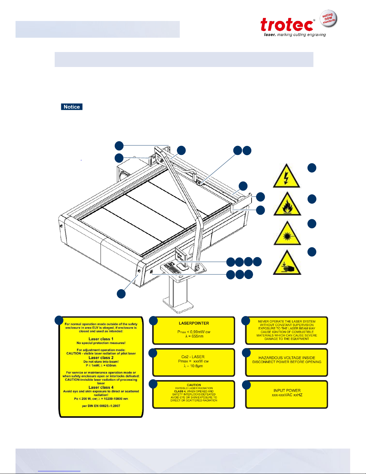
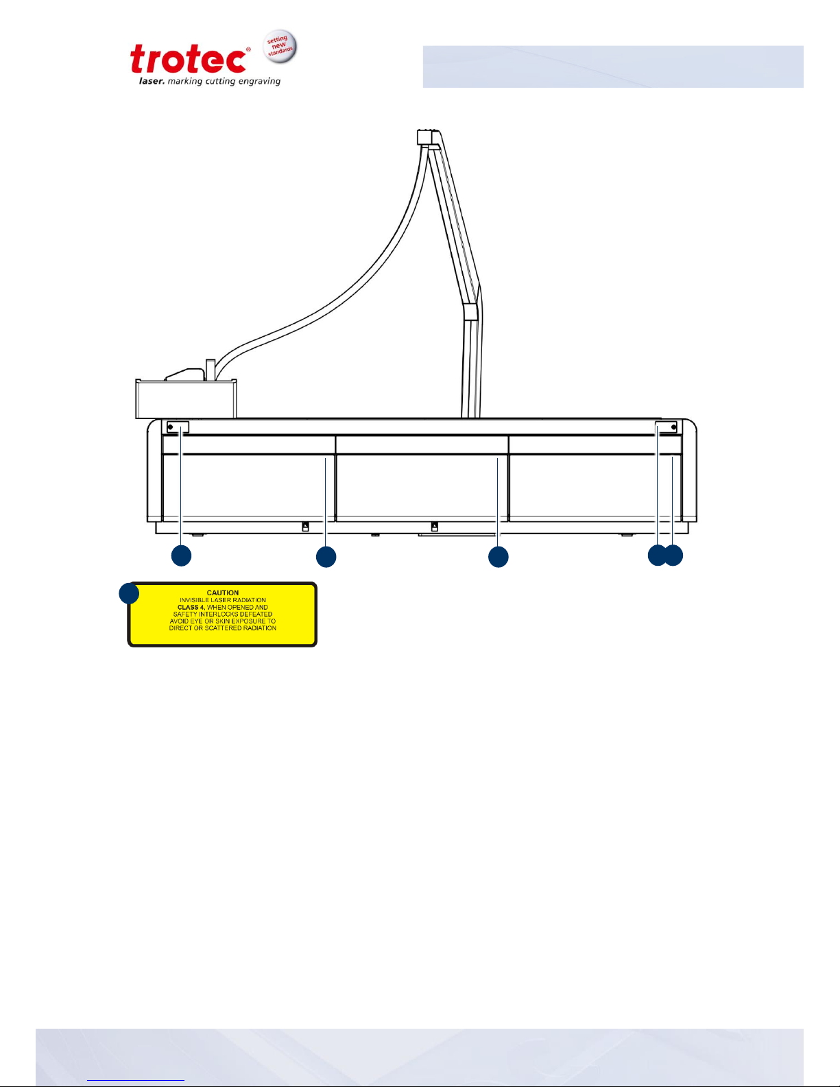
2.5 Warning and information labels
The warning and information labels are attached in the positions of the machine that could represent a
source of danger during set-up and operation. Therefore, pay attention to the information on the
labels.
Lost or damaged warning and information labels
If any warning and information labels are lost or damaged, the user is not able
identify risks anymore, and there is danger of injury.
- Replace lost or damaged labels immediately.
- Please contact your Trotec dealer for details.
1 2 3
4
3 9 2
6 7 5
8
84 4 4 4
3
5
11
1
10
6
7
8
9
10
11
Page 21
SP3000
Safety
BA 8034_2.4_EN (12/2016) 21 / 87
www.troteclaser.com
8
8
8
8
8
8
Page 22
SP3000
Safety
22 / 87 BA 8034_2.4_EN (12/2016)
www.troteclaser.com
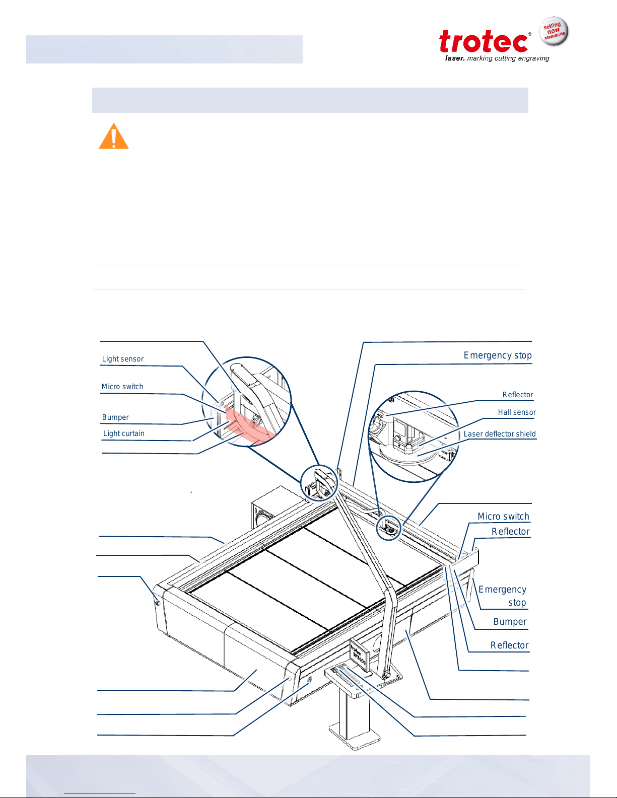
2.6 Safety devices
WARNING
Danger from laser beam
Safety and protection devices that are not installed or are not fully functional can lead to
bodily injury and material damage.
- Do not remove, modify or deactivate the safety interlock switches or protective covers
on the machine. Safety and protection devices must be fully functional at all times.
- In case of assumed or presumed damage of safety devices, disconnect the machine
from the mains.
- Damaged safety and protection devices need to be replaced by a Trotec technician
immediately.
2.6.1 Overview
The machine is equipped with the following safety devices:
Key switch
Emergency stop
Reflector
Main switch
Emergency stop
Emergency stop
Dust protections belt
Reflector
Micro switch
Hall sensor
Laser deflector shield
Emergency stop
Reflector
Side panel
Front cover
Side panel
Back cover
Light sensor
Bumper
Emergency
stop
Light curtain
Bumper
Micro switch
Light sensor
Warning lamp
Light sensor
Light curtain
Page 23

SP3000
Safety
BA 8034_2.4_EN (12/2016) 23 / 87
www.troteclaser.com
2.6.2 Main switch
Turn the main switch anticlockwise to disconnect the machine from the mains power supply.
2.6.3 Key switch
Turning the key switch powers off the motor, laser source and electric system, and prevents unauthorized operation.
2.6.4 Emergency stop button
The machine has five emergency stop buttons.
When pressing an emergency stop button the electric circuit immediately shuts off. The laser beam is
interrupted, and all movements are stopped.
The function of the emergency stop device is:
Firstly: to prevent any risks to the operating personnel.
Secondly: to avoid any damage to/destruction of the machine/material.
2.6.5 Casing elements, side panel and covers
Casing elements, covers and side panels protect from laser light and must always be closed and
properly attached.
2.6.6 Warning lamp
The warning lamp sends out visual and acoustic signals.
Status
Description
Red
flashing
-Interlock-mode: Error
Red + accustic signal
flashing
-Faulty safety devices
Yellow
permanent
-Busy-mode: data processing or receiving
-Testpuls-mode: carrying out a test pulse
Yellow - green
permanent
-Pause-mode
Green
permanent
-Idle-Mode: machine is ready
-Fully functional safety devices
Page 24

SP3000
Safety
24 / 87 BA 8034_2.4_EN (12/2016)
www.troteclaser.com
2.6.7 Bumper and micro switch
The spring-loaded bumper and corresponding micro switch provide object detection.
If an object gets detected the safety circuit is interrupted and subsequently the movement of the axis,
the current job processing and the laser emission stop immediately.
2.6.8 Light curtain
The light curtain provides access detection for hazardous areas. It is located in front of the X-axis and
is 16 cm (6.29 inch) high.
If an object gets detected the safety circuit is interrupted and subsequently the movement of the axis,
the current job processing and the laser emission stop immediately.
2.6.9 Laser deflector shield and hall sensor
The laser deflector shield absorbs a majority of scattered or reflected radiation in the area of the laser
beam output and is therefore mandatory during operation.
The presence of the magnetically fixed laser deflector shield is monitored via hall sensors. If the laser
deflector shield was removed on purpose or due to collision with a work piece, the safety circuit is
interrupted and subsequently the movement of the axis, the current job processing and the laser
emission stop immediately.
2.6.10 Light sensor and reflector
The light sensor and reflector provide access detection for hazardous areas. If an object gets detected
the safety circuit is interrupted and subsequently the movement of the axis, the current job processing
and the laser emission stop immediately.
2.6.11 In case of safety device malfunction
In case of actual or presumed damage to the safety devices:
Press the emergency stop button
Disconnect the machine from the mains
Please contact your local Trotec Support
Page 25

SP3000
Safety
BA 8034_2.4_EN (12/2016) 25 / 87
www.troteclaser.com
2.7 In case of an emergency
2.7.1 In case of malfunction
In case of unusual operating states, open the acrylic top lid to stop working process or respectively
press the emergency stop button, if available and switch off the laser device.
When appropriate disconnect the machine from the mains.
Inform laser protection officer and supervisor.
Follow the operating instructions.
Have repair work performed by Trotec service technicians only.
In case of fire: Use only CO2 extinguisher to quench the fire, insofar as this is possible without
endangering yourself.
2.7.2 In case of accident, First Aid
If due to laser irradiation eye injury has occurred (upon exceedance of the maximum allowable
irradiation rate), the accident victim must immediately be presented to an ophthalmologist.
Assumption of eye injury is justified whenever laser irradiation has occurred and the maximum
allowable irradiation rate may have been exceeded.
First Aider must pay attention to self-protection.
Power off the device.
Remove injured person from the danger zone and provide First Aid. Call emergency physician!
Page 26

SP3000
Safety
26 / 87 BA 8034_2.4_EN (12/2016)
www.troteclaser.com
2.8 Specific hazards
2.8.1 Fire hazard
WARNING
Fire hazard
Fire hazard from gas and processing of inflammable materials.
- Do not operate the device without supervision.
- Keep CO2 fire extinguisher ready at hand in the immediate vicinity of the device.
If a main laser beam comes into contact with inflammable material, e.g. paper, the latter may ignite,
quickly leading to fire. Therefore, before switching on the laser and after deactivating the standby
mode you must make sure that there is no inflammable material in the path of the beam.
Furthermore, gases formed beneath the material being processed may ignite, especially if the
extraction requirements are not met.
The risk of flaming is increased in case of insufficient care and cleaning as well.
Additionally, regularly control the air cooling system on your laser. In particular, the filters and
ventilators should be checked regularly for proper function so as to avoid defects caused by
overheating.
2.8.2 Gases, fumes and dust
Depending on the materials being processed and the parameters selected, laser processing may
generate gases, fumes, aerosols or dust. Depending on the material, such by-products may be toxic.
In individual cases, the reaction products may be electrically conductive dusts. If these enter electric
systems, short-circuiting with personal injury and property damage may occur.
The operator is responsible for ensuring presence of a suitable extraction system and compliance with
the relevant guidelines in order to protect persons and the environment. The guideline VDI 2262 1-3
“Workplace air” provides, among other things, additional remarks.
The operator must also ensure that gases, fumes or dust do not settle on the processing lens. Any dirt
accumulating on the processing lens can lead to loss of performance, poor processing results and
damage to the device.
Page 27
SP3000
Safety
BA 8034_2.4_EN (12/2016) 27 / 87
www.troteclaser.com
2.8.3 Reflecting material
WARNING
Danger from laser beam
Invisible laser radiation of reflecting materials can cause serious injury or material damage.
- Only material according to the intended use of the machine may be used
- Do not use material with high reflecting surfaces such as aluminum, chromium, precious
metals, metal foils, stainless steel, brass, copper and titanium
- Take special care with surfaces formed convex and concave
- Do not leave or put objects on the work surface / working area
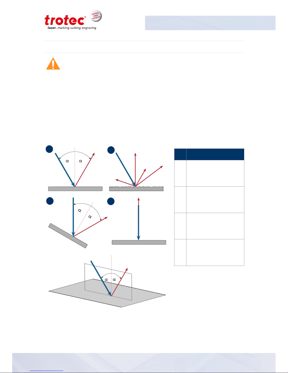
2.8.3.1 Laser beam reflection
The reflecting law is valid for the reflection of the laser radiation: Angle of incidence = failure corner
No
Description
1
Directed reflection
Reflected ray on smooth
surface
2
Directed reflection
Reflected ray on sloping
surface
3
Diffuse reflection
Reflected ray on rough
surface
4
Directed reflection
Horizontally reflected ray
on smooth surface
1 2 3
4
Page 28

SP3000
Safety
28 / 87 BA 8034_2.4_EN (12/2016)
www.troteclaser.com
2.8.4 Optical components
WARNING
Damage to optics
Soiled optics absorb laser radiation and can thus be destroyed. Broken or damaged
lenses as well as thermal decomposition of lenses release particles which cause serious
damage to the health.
- The passive reflectors and optics in the area of the beam guidance should be
cleaned regularly.
- Special care is required when handling, attaching and cleaning these elements.
- Do not exert non-uniform pressure.
- Do not use tools or hard objects to clean the surface.
- Never touch the optics with your bare fingers.
- Never use cleaning tissues twice.
- When lenses get broken, damaged or thermal decomposed follow the protective
measures.
- Disposal according to regulations and laws valid in the users' country.
- Lenses with scratches or penetrations must not be used anymore!
2.8.4.1 Scratched or destroyed lens surface
Be aware that scratches in the coating may release small quantities of thorium, which may be harmful
upon inhalation or swallowing.
2.8.4.2 Thermal decomposition
Upon thermal decompositions, vapors of selenium oxide and zinc oxide are formed. Upon inhalation or
swallowing there is danger of poisoning.
Indicators for thermal decomposition of ZnSe include deposits in the form of red or white powder and
an unpleasant odor.
2.8.4.3 Broken lenses
When optical components of zinc selenide (ZnSe) are destroyed, toxic dusts and vapors are formed
which must not be inhaled. The dust can additionally cause irritations of the eyes, skin and respiratory
tract.
If a lens has been destroyed during operations, care is to be taken during removal and cleaning.
Page 29

SP3000
Safety
BA 8034_2.4_EN (12/2016) 29 / 87
www.troteclaser.com
2.8.4.4 Protective measures
Protective measures in case of thermal decomposition and scratched or broken lenses
- For disposal use a protective mask or respiratory filter to prevent inhalation or ingestion of
thorium.
- Wash hands thoroughly after contact with a scratched coating.
Protective measures in case of a broken lens
- Upon perception of an unpleasant odor, switch off the machine.
- Hold your breath.
- Leave the area of the machine.
- Before approaching the system again, wait for at least 30 min until the reaction has
abated.
- Wear proper protective clothing (respiratory protection, protective goggles, protective suit,
rubber or plastic gloves).
- Provide ventilation.
- When approaching the system again, pay attention to odors.
- Remove all lens fragments.
- Avoid raising or dispersing dust.
2.8.4.5 Disposal
The ZnSe dust and the lens are to be collected drily and disposed of with fragments,
broom, shovel and protective clothing into hermetically sealable containers or
plastics bags as hazardous waste.
Do not dispose of optical components as domestic waste, and do not let them
enter the sewer or water bodies.
Dispose of according to regulations and laws valid in the users' country.
Page 30

SP3000
EC Declaration of Conformity
30 / 87 BA 8034_2.4_EN (12/2016)
www.troteclaser.com
3 EC Declaration of Conformity
(Machine directive 2006/42/EG, appendix II A)
Manufacturer:
TROTEC Laser GmbH
Linzer Straße 156,
A-4600 Wels
Authorized person for the compilation of technical documentation:
Gerhard KREMPL, TROTEC Laser GmbH, Linzer Straße 156, A-4600 Wels
We hereby certify that
SP 3000
Modell N° 8034 SP 3000
in its conception, construction and form put by us into circulation is in accordance with all the relevant
essential health and safety requirements of the EC machinery directive 2006/42/EEC.
Further valid guidelines/regulations for the product:
2006/95/EG Low Voltage Directive
2004/108/EG EMC Guideline
Applied harmonized standards:
- EN ISO12100 Machine Safety
- EN 60335-1/2007 Safety of Household and similar Appliances
- EN 55014-1/2006, EN 55014-2/1997 Electromagnetic Compatibility
- EN 60204-1 Machine Safety – electr. Equipment
- EN 60825-1/2007, EN 60825-4/2006 and EN 60825-14/2006 Safety of Laser Equipment
- EN 55022/2008, EN 55024/2003 Electromagnetic Compatibility
Place, Date:
Wels, 29th September 2016
Personal data of the signer:
Georg ERNST, Leiter Forschung und Entwicklung
Signature:
Page 31

SP3000
Technical Data
BA 8034_2.4_EN (12/2016) 31 / 87
www.troteclaser.com
4 Technical Data
4.1 Data sheet
Mechanics
Working area
2.210 x 3.210 mm (87 x 126 in)
Loading area
2.500 x ∞ mm (98 x ∞ in)
Max. height of work piece
50 mm (1.96 in)
Working head
Software controlled z-axis
Working table
Slat cutting table, aluminum cutting grid table, acrylic cutting grid table
or honeycomb cutting table
Max. processing speed
1 m/s (40 ips) (standard); 2 m/s (79 ips) (optional)
Acceleration
10 m/s² (393 ips²)*
Motors
Brushless DC servo motors
Encoder
Incremental measuring system
Optical elements
Telescope, lens and all mirrors air-flushed protected from soiling
Lens
2.5" (standard); 3.75“, 5.0" (optional)
Accuracy
+/- 0,1 mm (0.004 in), over the whole working area
Addressable accuracy
0,001 mm (0.00004 in)
Accuracy to size of parts
According to material and process
Maximum material load
200 kg (440 lbs.), load over the whole working area
InPack TechnologyTM
Protects working head and all moving parts from dust; harsh
environment protection kit included
Exhaust
Table exhaust for entire working area
Gas-Kit
Control of compressed air and process gas with max. 6 bar (87 psi),
built in filter-unit (free of mechanical dust, water and oil, max. flow rate
240 l/min, max. input 10 bar (145 psi), hose diameter 6 mm (0.23 in))
Software
JobControl® Expert
Interface
USB, RS-232 / ASCII, HPGL, AD-Logic System
Operating console
Keypad, safety-switch, system turnkey; workspace for mouse,
keyboard, monitor, drawer for tools; PC and Monitor not included
* Depending on configuration
Page 32

SP3000
Technical Data
32 / 87 BA 8034_2.4_EN (12/2016)
www.troteclaser.com
Laser
Laser system
Sealed-off CO2 laser
Laser power
60, 100, 200 and 400 watts
Cooling
Water cooled
Wavelength
10,6 µm
Options
JobControl® Vision
Camera compensation system for print & cut applications
Travelling exhaust
Exhaust mounted to working head
Digital table exhaust
Digitally controlled sectioning of table exhaust; 4 exhaust sections
Chiller
For all power levels
Sonar TechnologyTM
Ultrasonic-based autofocus system
TroCAM Basic / Advanced
CAD / CAM software for perfect cutting results; nesting-function, leadin/lead-out, tool paths, etc. included
TroCare
Comprehensive package of technical services
Dimensions (W x D x H) & Weight
Machine
3.076 x 3.914 x 1.230 mm (121 x 154 x 49 in)
1.600 kg (3.530 lbs.)
Chiller
720 x 835 x 930 mm (117 x 33 x 37 in) (400 watts model)
130 kg (287 lbs.) (400 watts model)
Operating console
800 x 600 x 1.126 mm (32 x 24 x 45 in)
40 kg (88 lbs.)
Travelling exhaust
2.082 x 714 x 2.852 mm (82 x 29 x 113 in)
165 kg (363 lbs.)
Safety
Laser class
Fully enclosed beam path CDRH laser class 4 laser; can be operated
like laser class 2 in standard operation mode
Laser safety
Fully enclosed beam path as well as active laser deflector shield at
working head
Mechanical safety
Light barriers and safety bumpers for beam path and gantry
Interlock
Encoded duplicate interlock safety system
Ambient conditions
Mandatory ambient temperature +15° to +25° C or 59° to 77° F
Humidity 40% to max. 70%, not condensing
Dust free environment (2nd degree according to IEC 60947-1)
Certificates
CE compliant
Page 33

SP3000
Technical Data
BA 8034_2.4_EN (12/2016) 33 / 87
www.troteclaser.com
Electrical & Exhaust
Exhaust working point
Min. 2.500 m³/h at 800 Pa (Min. 1.200 cfm at 8.900 in H2O)
(Table exhaust)
Min. 100 m³/h at 4.450 Pa (Min. 60 cfm at 17.865 in H2O)
(Travelling exhaust)
Minimum requirement for acrylic cutting; Depending on application
Voltage & power consumption
(Machine without chiller
3x400V (3xL+N+PE) 50/60Hz, max. 1,6 kW (60 watts)
3x400V (3xL+N+PE) 50/60Hz, max. 3,1 kW (100 watts)
3x400V (3xL+N+PE) 50/60Hz, max. 4,5 kW (200 watts)
3x400V (3xL+N+PE) 50/60Hz, max. 8,4 kW (400 watts)
Page 34

SP3000
Technical Data
34 / 87 BA 8034_2.4_EN (12/2016)
www.troteclaser.com
4.2 Dimensions and weight
4.2.1 Machine dimensions and weight
4.2.1.1 Front view
1227 mm / 49 in
3078 mm / 122 in
1165 mm / 46 in
820 mm / 33 in
4.2.1.2 Side view
3830 mm / 151 in
3914 mm / 154 in 60 mm / 2.4 in
700 mm / 28 in
Page 35

SP3000
Technical Data
BA 8034_2.4_EN (12/2016) 35 / 87
www.troteclaser.com
4.2.1.3 Side view (exhaust connection)
4.2.1.4 Top view
3210 m m / 126 in
60 mm / 2.4 in3914 m m / 154 in
3076 mm / 121 in
2210 mm / 87 in
4.2.1.5 Weight
The weight of the machine is 1.600 kg (3.530lbs).
Page 36

SP3000
Technical Data
36 / 87 BA 8034_2.4_EN (12/2016)
www.troteclaser.com
4.2.2 Operation panel exterior dimension
4.2.2.1 Side, front and top view
600 mm / 24 in
500 mm / 20 in 50 mm / 2 in
800 mm / 32 in
700 mm / 28 in
1100 mm / 44 in
1126 mm / 45 in
50 mm / 2 in
600 mm / 24 in
800 mm / 32 in
Page 37

SP3000
Technical Data
BA 8034_2.4_EN (12/2016) 37 / 87
www.troteclaser.com
4.2.3 Travelling exhaust exterior dimensions
4.2.3.1 Front –and side view
2082 mm / 82 in
750 mm / 30 in 800 mm / 6 in
2852 mm / 113 in
100 mm / 4 in
714 mm / 29 in
2852 mm / 113 in
4.2.3.2 Top view
714 mm / 29 in
800 mm / 6 in750 mm / 30 in
2082 mm / 82 in
Page 38

SP3000
Technical Data
38 / 87 BA 8034_2.4_EN (12/2016)
www.troteclaser.com
4.2.4 Exhaust with sound-insolating enclosure (optional)
Außenabmessung
VENT SP3000 Set:
VENT 100 (l x b x h)
(without sound-insulating enclosure)
VENT 1500 (l x b x h)
(with sound-insulating enclosure):
363 x 371 x 357 mm
(14,29 x 14,60 x 14,06 inch)
969 x 754 (with rotary handle) x 1076 mm
(38,15 x 29,69 (with rotary handle) x 42,36 inch)
Page 39

SP3000
Technical Data
BA 8034_2.4_EN (12/2016) 39 / 87
www.troteclaser.com
4.3 Materials
Material
Cutting
Engraving
CO2
CO2
Plastik
Acrylonitrile butadiene styrene (ABS)
Acryl/PMMA (Plexiglas®, Altuglas®, Perspex®)
Laminate
Rubber
Polyamide (PA)
Polybutylene terephthalate (PBT)
Polycarbonate (PC)
Polyethylene (PE)
Polyester (PES)
Polyethylene terephthalate (PET)
Polyimide (PI)
Polyoxymethylene
(POM) - Delrin®
Polypropylene (PP)
Polyphenylene sulfide (PPS)
Polystyrene (PS)
Polyurethane (PUR)
Foam
Page 40

SP3000
Technical Data
40 / 87 BA 8034_2.4_EN (12/2016)
www.troteclaser.com
Material
Cutting
Engraving
CO2
CO2
Additional
Wood
Mirror
-
-
Stone
-
Paper (white)
Paper (colored)
Food
Leather
Fabric
Glass
-
Ceramics
-
-
Cork
WARNING
Prohibited materials:
Carbon, polyvinyl chloride (PVC), polyvinyl butyral (PVB), polytetrafluorethylene (PTFE,
Teflon®), carbon fiber, beryllium oxide and materials containing halogens (fluorine,
chlorine, bromine, iodine and astatine), epoxy-based or phenolic resins
Take care when processing the following materials:
Manganese, chromium, nickel, cobalt, copper and lead. Any material with the naming
addition “flame-retarding” since it might contain bromine.
WARNING
Serious injury or material damage.
The use of prohibited or unreleased materials can cause serious injury or material
damage and will not be covered under warranty.
- Only use approved and released materials.
For any material not listed above please contact our application specialists or sales
office in your area.
We recommend performing a material processing test with the above mentioned
material, using the appropriate configuration.
Trotec assumes no responsibility for any consequences of laser processing in any
application, especially with medical or pharmaceutical applications.
Page 41

SP3000
Machine overview
BA 8034_2.4_EN (12/2016) 41 / 87
www.troteclaser.com
5 Machine overview
5.1 General overview
No
Description
No
Description
1
Emergency stop button
12
X-axis
2
Dust protection belt
13
Reflector
3
Side panel
14
Traveling exhaust
4
Tables
15
Monitor
5
Light sensor
16
Key switch
6
Bumper
17
Keyboard
7
Warning lamp
18
Connection cables (mains, exhaust and cooling system)
8
Head exhaust hose
19
Main switch
9
Laser head
20
Type plate
10
Hall sensor
21
Front and back cover
11
Laser deflector shield
22
Operating console
1
1
10
20
1
2
11
5
5
16
1
15
14
3
12
9
21
13
8
5
7
6
3
19181
4
5
13
13
17
22
Page 42

SP3000
Machine overview
42 / 87 BA 8034_2.4_EN (12/2016)
www.troteclaser.com
5.2 Operating elements
5.2.1 Operating elements overview
Compressed air display
Button: Emergency stop
Buttons: Exhaust segment
Compressed air regulator
Button: Max. compressed air
/ control lamp
Key switch
Operation panel
Laser information
Page 43

SP3000
Machine overview
BA 8034_2.4_EN (12/2016) 43 / 87
www.troteclaser.com
5.2.2 Operation panel
Status indicator: Laser beam
LED ON: The machine is processing data
Button: Laser head
(Z-position)
-Up
-Down
Focus automatically
Button: Home
LED ON: Home position
temporarily changed
Button: Standby
LED ON: Standby-mode
LED OFF: Ready-mode
Button: Laser head
(X/Y-position)
-X-axis direction
-Y-axis direction
Button: Shift
Second operating level
Button: Exhaust
LED ON: Exhaust active
Status LEDs
Green,
flashing slowly
(0.5 Hz)
Machine is
Ready
Covers closed
Green,
flashing fast
(2 Hz)
Cover is open
Blue and green
permanent
Data available
Pause- mode
Green,
permanent
Receiving or
processing data
Button: Start/Pause/Repeat
LED ON: Pause-mode
Button: Stop
Page 44

SP3000
Machine overview
44 / 87 BA 8034_2.4_EN (12/2016)
www.troteclaser.com
Description
Status indicator:
Laser beam
LED ON: The machine is processing or receiving data.
Button:
Standby
LED ON: Standby-mode
LED OFF: Ready-mode
Press the button to switch to Standby-mode.
Press the button again to switch back to Ready-mode.
When the button is pressed while the laser head is moving up or
down (e.g. during autofocus), the machine enters Standby-mode
only after finishing the movement.
Button:
Home
LED ON: Home position temporarily changed
Press the button for 3 sec. to temporarily define the position of the
laser head as home position. (Marker in JobControl®)
To deactivate the temporary home position, press Shift + Home.
Button:
Laser head (X/Y-
position)
Press the button to manually move the laser head to the right, left,
front or back.
Press two of the four X/Y position keys simultaneously to move the
laser head diagonally.
Press Shift together with one of the X/Y position keys to move the
laser head quickly to the corresponding end position.
Button:
Laser head (Z-
position)
Press the button to manually move the laser head up or down.
(Z-position)
Press Shift together with the Z-position up key to move the laser
head to the corresponding end position. To stop the movement
press any Z-position key.
With option Sonar Technology™:
By simultaneous pressing of the two keys for Z-positioning laser
head keys, the laser beam gets automatically focused on the
workpiece.
Press Shift together with the Z- position down key to move the laser
head into the autofocus positon. To stop the movement press any
Z-position key. For further information see chapter “Focusing”.
Page 45

SP3000
Machine overview
BA 8034_2.4_EN (12/2016) 45 / 87
www.troteclaser.com
Button: Stop
Press the button to stop the current working process.
Button:
Start/Pause/Repeat
Press the button to start the job which is currently on the plate in
JobControl®.
If a job is currently being processed, press the button to pause the
job (LED ON). Press the button again to continue the interrupted
working process (LED OFF).
Press the button after a job was finished to repeat the actual job
positioned on the plate in JobControl®.
Status LEDs
Indicates the current status of the machine:
Green, flashing slowly (0.5 Hz)
Machine is ready. All covers closed
Green, flashing fast (2 Hz)
Cover is open
Blue and green, permanent
Data available Pause- mode
Green, permanent
Receiving or processing data
Button: Shift
For second operating level. Press the button together with any of
the following keys to activate the following functions:
Shift functions:
Shift + Exhaust
Air assist on/off
Shift + Laser head (X/Yposition)
Laser head moves quickly to
corresponding end position (X- or Yposition)
Shift + Standby
Keypad locked/unlocked
Shift + Laser head UP
Laser head moves up to the
corresponding end position
Shift + Laser head DOWN
Laser head moves down in the
corresponding end position
With option Sonar Technology™:
Laser head moves into the autofocus
position
Shift + Home
Deactivated temporary home position
Button:
Exhaust
Press the button to switch the exhaust on or off.
LED ON: Exhaust activated
LED OFF: Exhaust deactivated
After completing the engraving process, the exhaust system can be
switched off only after a few seconds more (follow-up time).
Page 46

SP3000
Machine overview
46 / 87 BA 8034_2.4_EN (12/2016)
www.troteclaser.com
5.2.2.1 Keyboard shortcuts
Shortcuts
Shift + Exhaust
Air assist on/off
Shift + Laser head (X/Y-position)
Laser head moves quickly to
corresponding end position (X- or Yposition)
Shift + Standby
Keypad locked/unlocked
Shift + Laser head (Z-position)
"UP"
Laser head moves up to the
corresponding end position
Shift + Laser head (Z-position)
"DOWN"
Laser head moves up to the
corresponding end position
With option Sonar Technology™:
Laser head moves into the autofocus
positon
Shift + Home
Deactivate temporary home position
Laser head (Z-position)
"UP"+"DOWN"
With option Sonar Technology™:
Working Table moves up, into autofocus
position (focusing automatically)
X/Y position laser head + X/Y
position laser head
Laser heads moves diagonally in the
corresponding direction
Page 47

SP3000
Machine overview
BA 8034_2.4_EN (12/2016) 47 / 87
www.troteclaser.com
5.2.3 Compressed air display
Display of the compressed air pressure.
By pressing the SET-button the output values can be switched between bar or psi.
The arrow buttons have no functionality.
5.2.4 Compressed air regulator
By turning the compressed air regulator the pressure can be adjusted.
If the pressure of the compressed air is set too high, it can cause damage
to the machine.
- The supplied pressure of the extern connected compressed air must
not exceed 10 bar.
- The maximum compressed air pressure during operation must not
exceed 6 bar.
5.2.5 Key switch
Turning the key switch counterclockwise powers off the motor, laser source and electric
system.
Through the key switch, operation by non-authorized personnel can be prevented.
5.2.6 Emergency stop button
When pressing an emergency stop button, the electric circuit immediately shuts off. The laser beam is
interrupted, and all movements are stopped.
Do not use the emergency stop button for the standard switch off procedure.
5.2.6.1 Emergency stop acknowledgement
1. Turn the emergency stop button
counterclockwise to unlock it.
2. Reboot the laser device to acknowledge the
laser fault.
Page 48

SP3000
Machine overview
48 / 87 BA 8034_2.4_EN (12/2016)
www.troteclaser.com
5.2.7 Exhaust segment button
The table exhaust system is divided into four independent segments.
By pressing one of the four exhaust segment buttons, the vaccum of the respective
section can be activated or deactivated. The working area which is free of material
must not be covered.
5.2.8 Max. compressed air / control lamp
Max. compressed air button: by pressing the button the maximum air pressure gets
switched on. This remains active as long as the button is pressed. The supply of the
maximum compressed air is used for example for blowing of any flame formation.
Control lamp: ON, whenever an exhaust or cooling system is not connected or not
active and therefore the interlock is not closed.
Page 49

SP3000
Machine overview
BA 8034_2.4_EN (12/2016) 49 / 87
www.troteclaser.com
5.3 Tables (multifunctional table concept)
5.3.1 Cutting tables
5.3.1.1 Aluminum slat / Acryl slat cutting table
The cutting table with aluminum slats is mainly
used for cutting thicker materials (up to 8 mm
thickness) and for parts wider than 100 mm.
Acrylics can be cut with no reflections by
exchanging the aluminum with acrylic slats.
One can reduce the number of supporting
points by removing slats individually, depending
on the
job.
5.3.1.2 Aluminum cutting grid table
This robust, universal cutting table is
characterized by extremely stable combs and a
long lifetime. It is particularly suitable for cutting
tasks with parts smaller than 100 mm, as these
remain in a flat position after the cut. Compared
to the cutting table the aluminum cutting grid
table has more supporting points.
Page 50

SP3000
Machine overview
50 / 87 BA 8034_2.4_EN (12/2016)
www.troteclaser.com
5.3.1.3 Acrylic slat cutting table
The universal cutting table for the reflection-free
cutting of thin acrylics with a thickness up to 8
mm. Like with the aluminum cutting grid table
parts smaller than 100 mm remain in a flat
position after the cut.
5.3.1.4 Honeycomb cutting table
This processing table is especially suitable for
applications that require minimal back reflections
and optimum flatness of the material, like for
example cutting films.
Page 51

SP3000
Machine overview
BA 8034_2.4_EN (12/2016) 51 / 87
www.troteclaser.com
5.4 Lenses
Lenses (incl. focus tool) available:
2,5” (Standard)
3,75"
5,0"
5.5 Nozzles
Nozzles available:
Ø 3
Short, small diameter
(Standard)
Ø 7
Short, big diameter
(Standard)
Page 52

SP3000
Transport, unloading and packaging
52 / 87 BA 8034_2.4_EN (12/2016)
www.troteclaser.com
6 Transport, unloading and packaging
6.1 Safety notes
WARNING
Risk of injury
There is risk of injury from falling parts during transport, loading and unloading of the
machine.
- Follow the safety instructions.
Observe the safety instructions to avoid damage to the machine from improper handling
during transport:
Always move the machine with utmost care and attention.
Transport the machine/machine components only in its original packaging.
Take the machine’s center of gravity into account when transporting it (minimize the risk of tipping
over).
Observe the packaging symbols (e.g. transport the machine only in upright position).
Take measures to prevent the machine from slipping sideways, tipping or falling over.
Transport the machine as carefully as possible in order to prevent damage.
Avoid vibrations.
When transporting the machine overseas, the device must be packaged airtight and protected
against corrosion.
When transporting outdoors, transport only in vehicles with roof or sufficient weather protection.
Protect the machine against transportation damage using straps and inserts, and leave sufficient
gaps to other transported items.
Do not place any other loads or items on the machine or machine components.
6.2 Delivery state
Unless otherwise agreed, the machine and additional accessories get delivered in wooden crates.
Please refer to the "Pre-installation Guide" for further information.
Keep the original packaging.
.
Page 53

SP3000
Transport, unloading and packaging
BA 8034_2.4_EN (12/2016) 53 / 87
www.troteclaser.com
6.3 Temperature and humidity
Ambient temperature for
transportation
-10 °C to 40 °C (-50 °F to 104 °F)
Humidity
max. 85% (non-condensing)
6.4 Required tools for unloading and transport
Unloading the packaged
machine parts
Transport the unpacked
machine parts
Type
forklift
pallet truck
Weight
weight ≥ 1.5 t
weight ≤ 1.5 t
Fork extension
approx.
2 m (78.74 inch)
approx.
2m (78.74 inch)
6.5 Relocation of the machine
Transport the machine only in its original packaging.
Ensure the wooden crates are properly secured otherwise the crates can slip, tip or fall
over during transport.
If you want to relocate the machine, please contact your local Trotec Support.
Page 54

SP3000
Setup and installation
54 / 87 BA 8034_2.4_EN (12/2016)
www.troteclaser.com
7 Setup and installation
7.1 Safety notes
WARNING
Risk of injury
Improper assembly or setup can cause serious injury or damage.
- Work may be carried out only by authorized, trained personnel who are familiar with
how to operate the machine and in strict observance of all safety instructions..
WARNING
Risk of injury
An incomplete, faulty or damaged machine can lead to serious physical injury or property
damage.
- Assemble and install the machine only if the machine and its parts are complete and
intact.
DANGER
Electric current
Work on electrical fittings may be carried out only by qualified personnel and in strict
observance of the safety notes.
Note the following:
If the system has been subject to significant temperature fluctuations, it must be brought back to
room temperature before being commissioned.
A laser system consists of high-quality electrical and optical components. Mechanical stresses,
vibrations and impacts must always be avoided
Ensure that there is sufficient distance to neighboring machines, walls or other fixed equipment.
Keep the work area orderly and clean.
Before assembling and installing the machine, check it to make sure it is complete and in good
condition.
Page 55

SP3000
Setup and installation
BA 8034_2.4_EN (12/2016) 55 / 87
www.troteclaser.com
7.2 Operating environment
7.2.1 Temperature and humidity
Operating temperature:
15 °C to 25 °C (59 °F to 77 °F)
Air humidity:
40% – 70% (non-condensing)
7.2.2 Subsoil conditions
Conditions:
- Planarity ±5 mm (±0.1969 inch)
- Solid, firm and vibration-free soil
- Easy-care and clean floor
- Bearing capacity of the subsoil ≥1000kg/m2 (10KN/m2)
- Machine point load 500kg/m² (5KN/m2)
- No special substrate preparation required
7.2.3 Environmental conditions
Conditions:
- Provide sufficient illumination at the workplace
- Ensure a dust-free environment (II° according to IEC60947-1)
- Shielding from EMC
- Freedom of interfering electrical installations, hoses and pipe lines
- Power supply free of fluctuations
7.3 Setup and installation
The setup has to be carried out by Trotec technicians only.
Page 56

SP3000
Setup and installation
56 / 87 BA 8034_2.4_EN (12/2016)
www.troteclaser.com
7.4 Connections
7.4.1 Connecting the mains
Wrong voltage can cause damage to the machine
Do not operate the machine, if the voltages do not match, as this may cause damage tot
he machine.
- The mains and operating voltage, as stated next to the connecting sockets must
match.
Connect the end of the mains cable to the main connection socket.
7.4.2 Operating console connection
The connection has to be carried out by a Trotec technician.
7.4.3 Connecting a Trotec exhaust system
Wrong voltage can cause damage to the machine
Do not operate the machine, if the mains voltage does not match the voltage required by
the exhaust system, as this may cause damage tot he machine.
- Make sure that the mains voltage matches the voltage required by the exhaust
system.
The connection has to be carried out by a Trotec technician.
Follow the operation and maintenance instructions in this manual of the exhaust system.
7.4.4 Connecting a Trotec cooling system
Wrong voltage can cause damage to the machine
Do not operate the machine, if the mains voltage does not match the voltage required by
the cooling system, as this may cause damage tot he machine.
- Make sure that the mains voltage matches the voltage required by the cooling
system.
The connection has to be carried out by a Trotec technician.
Follow the operation and maintenance instructions in this manual of the cooling system.
Page 57

SP3000
Operation
BA 8034_2.4_EN (12/2016) 57 / 87
www.troteclaser.com
8 Operation
8.1 Before operation
WARNING
Risk of injury
Improper operation may lead to severe physical injury or property damage.
- Work may be carried out only by authorized, trained personnel who are familiar with
how to operate the machine and in strict observance of all safety instructions.
Before commissioning, the following points need to be checked:
Check the machine and its safety devices to ensure that they are in working order, in technically
flawless condition and complete.
Keep work area orderly and clean. Source of accidents!
Ensure that the optical components are free from dust and dirt.
Activate the extraction system.
Ensure that the electrical installation is complete and the input voltage is correct.
Check the environmental conditions using the technical specification.
Familiarize yourself with the laser safety regulations.
Fulfil all laser safety requirements.
The system may be switched on only when all provisions for complying with laser safety have
been checked by an authorized person and confirmed to have met the standards.
8.2 Software
For information on how to use the software, please read the accompanying software manual, which
can be found on the supplied DVD.
Page 58

SP3000
Operation
58 / 87 BA 8034_2.4_EN (12/2016)
www.troteclaser.com
8.3 Power ON/OFF
8.3.1 Power ON
1. Ensure that no objects of any kind are present inside the
processing area that could limit or obstruct the freedom of
movement of the mechanics of the device.
2. Ensure that all safety devices are present and fully
functional and the side panels are closed.
3. Turn on the cooling system by clockwise turning the main
switch located at the back of the system to the right.
4. Switch on the compressed air supply.
5. Turn on the main power of the machine by clockwise
turning the main switch. The main switch is located at the
right front side of the machine
Page 59

SP3000
Operation
BA 8034_2.4_EN (12/2016) 59 / 87
www.troteclaser.com
6. Turn the key switch clockwise and hold against the
spring force. As soon the machine is started, release
the switch. The switch returns to its initial position.
Only if the cooling system was switched
on beforehand, the safety circuit gets
closed and the machine can be turned
on.
7. The machine starts the referencing process approx. 25
seconds after switching it on.
8. As soon the referencing process is correctly completed
and an acoustic signal sounds, the machine is ready for
operation.
Additionally the ready-to-use state is indicated through
the slow flashing of the green status LEDs..
Page 60

SP3000
Operation
60 / 87 BA 8034_2.4_EN (12/2016)
www.troteclaser.com
8.3.2 Power OFF
1. Turn the key switch counterclockwise.
2. Turn off the main power of the machine by turning the main
switch counterclockwise. The main switch is located at the
right front side of the machine.
By switching off the mains, all processing data are
lost.
3. Switch off the compressed air supply.
4. Turn off the cooling system by counterclockwise turning the
main switch located at the back of the system.
5. Clean the machine and ensure that no objects of any kind
are present inside the processing area.
Page 61

SP3000
Operation
BA 8034_2.4_EN (12/2016) 61 / 87
www.troteclaser.com
8.4 Lens placement
1. Blow away loose particles and dust by means of a
bellows or compressed air (according to ISO
8573:2010 class 1).
2. Unscrew the lens fixation screws. (2 screws)
3. Carefully take out the lens.
4. Check the lens for damage.
5. If necessary, clean the lens with cleaning liquid and
cleaning tissue (see chapter “Cleaning the optics”)
6. Check the lens once more for damage.
7. Insert the lens.
8. Fixate the lens with the fixation screws.(2 screws)
Page 62

SP3000
Operation
62 / 87 BA 8034_2.4_EN (12/2016)
www.troteclaser.com
8.5 Table placement
Damage to the multifunctional base frame or impairment of the exhaust function
When workpieces are processed directly in the multifunctional base frame without a
table, the base frame can be damaged, and impairment of the exhaust function is
possible.
- Process workpieces only on suitable tables.
1. The working area offers space for four tables.
Place the suitable tables on the multifunctional
base frame.
Two person are required for the
placement of a table.
2. Fixate the two outside tables by inserting a
fixation strip at the side.
3. For more details about available table varieties
see chapter "Tables".
Page 63

SP3000
Operation
BA 8034_2.4_EN (12/2016) 63 / 87
www.troteclaser.com
8.6 Focusing methods
8.6.1 Overview
Precise laser engraving depends on several factors. Apart from the right choice of lens, working tables
and a corresponding exhaust system, correct focusing plays a key role.
The correct setting of the focus, which means the right distance between the laser head and the
material to be engraved, is crucial for a perfect application result.
Manual focus mode
- Focus tool
Automatic focus modes
- Software focus (JobControl®)
- Sonar Technology™ (automatic focusing with ultrasonic sensor)
Defects from head crashes (working head hits material or working table) are excluded
from warranty.
Page 64

SP3000
Operation
64 / 87 BA 8034_2.4_EN (12/2016)
www.troteclaser.com
8.6.2 Focus tool
1. Move the processing head over the material
to be engraved by means of the X/Y position
keys (2) on the keypad.
2. Hang the focus tool (3) on the allocated space
on the laser head so that the focus tool can
move unhindered.
3. Move the X-axis downwards by pressing the
laser head (Z position) key (1).
4. Before the focus tool reaches the work piece,
move the working table downwards very
slowly and step by step by briefly tapping the
laser head (Z position) key (1) until the focus
tool tilts to the side or falls off its position.
Now the lens is focused onto the surface of
the material.
1
2
3
Page 65

SP3000
Operation
BA 8034_2.4_EN (12/2016) 65 / 87
www.troteclaser.com
8.6.3 Software focus
The following values must be entered in JobControl®:
Table type
Lens type
Material thickness (exact measurement)
Material process type
The values entered must match the material, table and lens in the machine in order to
avoid a head crash.
When using spacer the total material thickness is determined by the thickness of the
spacer and the material.
1. Click on the icon "Options" or go to
Settings/Options in the menu.
2. Select "Accessories".
3. When you are using a cutting table
enter the table type and the thickness
of the table.
4. Select the lens type in the menu bar.
5. Click on the icon "Material
database" or got to Settings/Material
database in the menu.
6. Enter the material thickness.
7. Enter the process type.
8. Click on the icon “Focus laser".
The working table moves automatically
to the correct position (moves in Z
direction).
Page 66

SP3000
Operation
66 / 87 BA 8034_2.4_EN (12/2016)
www.troteclaser.com
8.6.4 Sonar Technology™
Strong contamination of the ultrasonic sensor can lead to defects from head crashes
(working head hits material or working table).
5. Make sure that the ultrasonic sensor is clean.
6. Select the lens type in the menu bar of JobControl®.
7. Press the two Z-positioning keys (1) simultaneously for the laser
beam to get automatically focused on the workpiece.
Focusing is then complete, and you can start the laser processing.
This focusing mode is especially well-suited for all sound-
reflective materials.
Page 67

SP3000
Maintenance
BA 8034_2.4_EN (12/2016) 67 / 87
www.troteclaser.com
9 Maintenance
9.1 Safety notes
WARNING
Improper maintenance can cause serious injury or damage.
Maintenance may be carried out only by authorized, trained personnel who are familiar
with how to operate the machine and in strict observance of all safety instructions.
WARNING
Risk of fire or explosion
Improper handling of the machine may cause fire or explosion.
- For cleaning the machine, do not use explosive or flammable substances or cleaning
agents.
- No flammable or explosive liquids may be stored in or near the machine.
- Always keep the system clean, and remove flammable parts from the working area
or exhaust area.
WARNING
Danger of electrical shock
Work on electrical fittings may be carried out only by qualified personnel and in strict
observance of the safety instructions.
- Before any maintenance work takes place, disconnect the machine from the
mains voltage and make sure the system is de-energized.
Page 68

SP3000
Maintenance
68 / 87 BA 8034_2.4_EN (12/2016)
www.troteclaser.com
9.2 Maintenance schedule
System Components
Daily
Weekly
Monthly
Yearly
Laser
Entire working area - general
cleaning
Clean
whenever
required
Lens and protective glas
Check
Clean
whenever
required
Laser deflector shield and
nozzle
Check
Clean
whenever
required
Laser head exhaust
Check
Clean
whenever
required
Every 6 month:
Check
Clean
whenever
required
Vent slots (inside the machine)
Check
Clean
whenever
required
Safety devices
Check
Clean
whenever
required
Ultrasonic sensor (Option)
Check
Clean
whenever
required
JobControl® Vision safety glass
(if available)
Check
Clean
whenever
required
Compressed air system
Maintenance unit
According to the operation manual of the compressed air system
Exhaust System
Bag filter
According to the operation manual of the exhaust system
Filter mat
Particle filter
Activated carbon filter
Cooling system
Pump filter
According to the operation manual of the compressed air system
Condense heater
Cooling liquid
Pump
In order to ensure the maximum availability and lifetime of the system, we recommend
that you regularly check the filter, ventilation and exhaust slots and keep the surrounding
area clean. A visual inspection of the lenses is likewise recommended before switching
on the system.
Page 69

SP3000
Maintenance
BA 8034_2.4_EN (12/2016) 69 / 87
www.troteclaser.com
9.3 Cleaning the machine
1. Move the X-axis into a position in which it is easiest for you to clean the surface and interior of the
machine with a window cleaning agent and paper towels.
2. Switch off and disconnect the machine from the mains.
3. Remove the tables.
4. Thoroughly remove all loose dirt particles and deposits in the interior of the machine (e.g. with a
vacuum cleaner or broom).
5. Clean the vent slots of the exhaust box inside the machine using a dry or damp cloth, broom or
vacuum cleaner.
6. Clean the cover elements and panels using a dry or slightly damp cotton cloth. Do not use paper
towels as they could scratch the acrylic.
Page 70

SP3000
Maintenance
70 / 87 BA 8034_2.4_EN (12/2016)
www.troteclaser.com
9.4 Cleaning the optics
Trotec recommends to use the cleaning set enclosed. Alternatively, use high-quality cotton swabs
together with the provided cleaning liquid.
The following cleaning products are available as accessory parts:
- Lens cleaning cloth (Part no. 69249)
- Lens cleaning liquid (Part no. 69248)
9.4.1 Lens design
9.4.2 Cleaning the lens
WARNING
Zinc selenide lens, telescope and laser exit window
Soiled optics absorb laser radiation and can thus be destroyed. Broken or damaged
lenses as well as thermal decomposition of lenses release particles which cause serious
damage to the health.
- The passive reflectors and optics in the area of the beam guidance should be cleaned
regularly.
- Special care is required when handling, attaching and cleaning these elements.
- Do not exert non-uniform pressure.
- Do not use tools or hard objects to clean the surface.
- Never touch the optics with your bare fingers (wear cloves).
- Never use cleaning tissues twice.
- When lenses get broken, damaged or thermal decomposed follow the protective
measures.
- Disposal according to regulations and laws valid in the users' country.
- Lenses with scratches or penetrations must not be used anymore!
Clamping ring
Sealing ring
Lens
Page 71

SP3000
Maintenance
BA 8034_2.4_EN (12/2016) 71 / 87
www.troteclaser.com
1. Blow away loose particles and dust by means of a
bellows or compressed air (according to ISO 8573:2010
class 1).
2. Get the cleaning liquid and cleaning tissues ready.
3. Move the table up and put a cloth under the lens holder
(so that the lens will not be damaged if it falls out of
holder by accident).
4. Unscrew the lens fixation screw.(1 screw)
5. Carefully take out the lens. (2 screws)
6. With the aid of the supplied key tool loosen the clamping
ring by rotating it clockwise.
Key tool
Page 72

SP3000
Maintenance
72 / 87 BA 8034_2.4_EN (12/2016)
www.troteclaser.com
7. Remove the clamping and sealing ring.
8. Carefully remove the lens and rinse it with cleaning liquid
to wash away coarse soiling.
9. Check the lens for sign of damage.
10. Put some cleaning liquid onto the lens and leave the
liquid for 1 minute to take effect.
11. Soak a cleaning tissue with cleaning liquid and carefully
wipe off the surface.
12. Now carefully insert the lens with the convex side up into
the lense holder.
13. Insert the sealing and clamping ring and fixate the
clamping ring using the key tool.
14. Carefully insert the lens with the lens holder into to laser
head and fixate it with the lense fixation screws. (2
screws)
Page 73

SP3000
Maintenance
BA 8034_2.4_EN (12/2016) 73 / 87
www.troteclaser.com
9.4.3 Cleaning the laser deflector shield and nozzle
1. Take off the magnetically fixed laser deflector shield.
2. Clean the laser deflector shield with a dry or damp cloth on
both sides.
3. Turn the nozzle clockwise to be able to take it out.
4. Fix back the laser deflector shield on the laser head.
9.4.4 Cleaning the protective glas
1. Take off the magnetically fixed laser deflector shield.
2. Clean the laser deflector shield with a dry or damp cloth
on both sides.
Page 74

SP3000
Maintenance
74 / 87 BA 8034_2.4_EN (12/2016)
www.troteclaser.com
3. Unplug the air assit hose..
4. Remove the fixation screw. (1 screw)
5. Carefully take off the protective glass housing.
Page 75

SP3000
Maintenance
BA 8034_2.4_EN (12/2016) 75 / 87
www.troteclaser.com
6. Turn the nozzle clockwise to be able to take it out.
7. With the aid of the supplied key tool loosen the clamping
ring by rotating it clockwise.
Key tool
Page 76

SP3000
Maintenance
76 / 87 BA 8034_2.4_EN (12/2016)
www.troteclaser.com
8. Remove the clamping ring.
9. Take out the protective glass.
10. Clean the protective glass with a dry or damp cloth on
both sides.
11. If necessary take out the sealing ring and clean the
housing with a dry or damp cloth.
12. Insert the sealing ring again.
13. Now carefully insert the protective glass and clamping
ring and fixate the clamping ring using the key tool.
14. Fix back the protective glass housing on the laser head.
Page 77

SP3000
Maintenance
BA 8034_2.4_EN (12/2016) 77 / 87
www.troteclaser.com
9.5 Cleaning the head exhaust
1. Loosen the fixation screw and remove the exhaust hose.
(1 screw)
2. Clean the air flow duct and connection point.
9.6 Cleaning the vent slots of the table exhaust
1. Move the table into a position in which it is easiest for you to clean the slots of the table exhaust
inside the machine.
2. Switch off and disconnect the machine from the mains.
3. Remove the tables.
4. Thoroughly remove all loose dirt particles and deposits in the interior of the machine (e.g. with a
vacuum cleaner or broom).
5. Clean the vent slots of the exhaust box inside the machine using a dry or damp cloth, broom or
vacuum cleaner.
9.7 Cleaning the ultrasonic sensor (Option Sonar Technology™)
The sensor can be cleaned either with a brush, or be wiped drily, with moisture or with mild detergents
and a microfiber or anti-statics cloth. In case of stronger soiling, isopropyl or ethanol solution can be
used.
Avoid long application time and long-term usage.
Page 78

SP3000
Maintenance
78 / 87 BA 8034_2.4_EN (12/2016)
www.troteclaser.com
10 Troubleshooting
This chapter should enable the maintenance personnel to identify and resolve operational faults based
on error messages and symptoms.
DANGER
Risk of fire from incorrect parameter settings
Laser operation with incorrect parameter settings such as power settings, speed or
frequency can result in flame formation.
- Laser operation permitted only under supervision.
System failures that cannot be remedied can cause damage to the machine.
- Disconnect the machine from the mains and contact your local support team.
10.1 Errors, cause and resolutions
Problem
Possible Cause
Resolution
Too low engraving depth
Imprecise focusing
Dirty optics
Check focus
Clean optics
Blurred edges
Imprecise focusing
Check focus
Missing cut lines
Zero passes in material
database
Line thickness in Corel
Draw too big
Color was skipped in
JobControl®
Increase the amount of
passes in the JobControl®
material database
Reduce line thickness to
smallest possible value
Set color to cutting in the
JobControl® database
Waviness of the lines
Lens is loose
Check lens and lens holder
No visible marking result
Too low laser power
Too high speed
Not focused
Wrong focus tool
Increase power setting
Reduce speed
Check focus
Change focus tool
When using Auto focus,
check the settings within
the software (lens, material
thickness, table)
Page 79

SP3000
Maintenance
BA 8034_2.4_EN (12/2016) 79 / 87
www.troteclaser.com
Problem
Possible Cause
Resolution
Fine details on stamps are
engraved too thinly
Too steep shoulders
Choose other shoulder or edit
(flat/medium/steep):
Options/Process
Options/Stamp
The size to be engraved or
cut does not match the
size in Corel Draw
Raster correction ON in
JobControl®
Wrong size settings in the
printer driver
Wrong image position is
selected in the layout tab
(printing)
Wrong machine is selected
in the JobControl®
Switch off raster correction in
JobControl®
(settings/advanced
options/laser tab)
Use the same size as in
Corel draw
Switch the layout settings to:
as in document
Select the proper machine in
JobControl®
Corners and angles are
not cut or marked
Power too low
Increase the correction in
JobControl® (Settings /
Material Templates Setup—
Correction)
No referencing after
startup
Top, front or side door not
closed
Close doors
No response upon
switching on of the
system
Fuse blown
No electric power at power
outlet
Check fuses
Check power outlet
No communication with
machine
Invalid COM port selection
Communication cable defect
COM: port is in use by
another program
Change selection
Check cable
Close this program, or
change the COM port
Connection to machine
frequently interrupted
Electromagnetic emissions
Make sure that machine and
computer are connected to
the same electric circuit;
the original cable lengths
should not be exceeded
Page 80

SP3000
Maintenance
80 / 87 BA 8034_2.4_EN (12/2016)
www.troteclaser.com
Problem
Possible Cause
Resolution
Offsets between
engraving jobs and cut
lines
Speed too high
Reduce speed
Other faults
Contact Trotec support
Page 81

SP3000
Contact details
BA 8034_2.4_EN (12/2016) 81 / 87
www.troteclaser.com
11 Contact details
11.1 Technical Support
In case of questions, contact our experienced local technical support team.
For global service contact numbers and further information please see our website, section “Support”:
www.troteclaser.com
When calling, please make sure that the machine is in your immediate vicinity, and that you
have the following information ready (see response form):
What happened and what you were doing when the problem arose.
What you have done so far to correct the problem.
Serial no (see type plate)
Error code
11.2 Local Offices / Sales
Our store locator and detailed information on our offices in your area can be found on our website in
section “Contact”, “Local Office”:
www.troteclaser.com
11.3 Technical Documentation
For feedback or to suggest changes to this manual, contact:
Technical documentation: +43 (0) 7242 239 - 7000
E-mail: techsupport@troteclaser.com
Page 82

SP3000
Disassembly
82 / 87 BA 8034_2.4_EN (12/2016)
www.troteclaser.com
12 Disassembly
The disassembly of the machine described within this manual may only be carried out by
Trotec support technicians. Please contact your local Trotec Support.
13 Disposal
Do not dispose of the machine with domestic waste!
Electronic devices have to be disposed of according to the regional directives on
electronic and electric waste disposal. In case of further questions, please ask
your supplier.
Use suitable tools if you have to disassemble the machine. All parts need to be
sorted into the individual material types and be disposed of according to the
regional directives on electronic and electric waste disposal.
Page 83

SP3000
Appendix
BA 8034_2.4_EN (12/2016) 83 / 87
www.troteclaser.com
14 Appendix
14.1 Acceptance form
Dear customer!
Please check applicable items:
We request your confirmation of
properly completed transfer of the
machine
Machine parts checked for shipping damage
Machine parts checked against delivery note
Setup of the machine discussed
Startup of the machine discussed
Operation of the machine discussed
Maintenance of the machine discussed
Electrical voltage checked
Safety notes discussed
Trial run performed
Deficiencies determined
The machine with the machine designation:
Please transmit a copy of this
document – filled out and signed
by an authorized company
representative – to an employee of
our sales affiliate for forwarding to
the manufacturer.
Thank you very much.
has been checked according to the listed items and has
been handed over properly.
City, Date
Instructed person:
Name/position
Company stamp / Signature
Page 84

SP3000
Appendix
84 / 87 BA 8034_2.4_EN (12/2016)
www.troteclaser.com
14.2 Training verification form
Employee/Trainee:
Trainer:
Date of Training:
The employee named above was instructed in the operation of the ……………………. laser system.
Especially the following topics were covered:
1. Machine Function
2. Danger Areas
3. Warnings
4. Position of Emergency Stop Button
5. Personal Protective Equipment
6. Operating Equipment
7. Work Flow
8. Setting Up
9. Taking into Service and Shutdown
10. Reporting of Unexpected Working Results and Actions to Be Taken
11. Reporting of Failure and Actions to Be Initiated
12. Responsibility for Troubleshooting
13. Operation Manual and its Storage Location for Inspection
............................................................... ...............................................................
Signature of Trainer Signature of Trainee
Page 85

SP3000
Appendix
BA 8034_2.4_EN (12/2016) 85 / 87
www.troteclaser.com
14.3 Response form
In case of any trouble with the machine, please provide the following information and additionally
create a service file (the procedure for creation of a service file is described on the following pages).
Date
Machine Details
Contact Details
Serial Number
First Name
JobControl®
Version
Last Name
Driver Version
Country
Layout Software
Phone
Firmware Version
Email
Problem Description
Does an error message show up on the PC; if so, which?
What happened before the error occurred? (Thunder & Lightning, Windows-Update, …)
What attempts were made to solve the problem?
Please send the information to your sales representative, your local support or to
techsupport@troteclaser.com.
Page 86

SP3000
Appendix
86 / 87 BA 8034_2.4_EN (12/2016)
www.troteclaser.com
14.4 How to create a service file
1. Start JobControl®.
2. Position the job that may cause the error on
the plate.
This can be done by either:
double clicking on the job in the queue
single-clicking the job in the queue and
dragging it onto the plate
single-clicking the job in the queue and
then clicking on the icon “Position Job”
.
3. Run the job and leave the job on the plate.
4. Go to “Settings” > “Create Service File”.
5. The window „Save Service File to” shows
up.
6. Please select a directory to save the file into
and click on „Save”.
Page 87

SP3000
Appendix
BA 8034_2.4_EN (12/2016) 87 / 87
www.troteclaser.com
7. The window „Add Layout File” appears.
8. Select the layout file that was sent to
JobControl® and possibly caused a failure
(e.g.: a CorelDraw file, Photoshop file,
AutoCAD file,…). Now click on „Open”.
9. The following window shows the location to
which the successfully created service file
was saved.
10. Send the service file “SeviceLog.txt”
together with a screenshot of the error
message and a detailed description to your
sales representative or to
techsupport@troteclaser.com.
 Loading...