

Page 1
SP1500 Operation Manual
Page 2

2 / 53 8018_SP1500 V2.2_EN (03/2018)
Copyright© by Trotec Laser GmbH
All rights reserved.
Anyone who reproduces, copies or distributes this document, or parts of it, without the approval
of Trotec Laser GmbH is subject to prosecution.
We do not assume liability for any errors contained in this documentation.
We reserve the right to make technical changes.
Trotec Laser GmbH
Linzer Strasse 156,
A-4600 Wels, OÖ.
AUSTRIA
Tel.: +43-(0)7242-239-0
Fax: +43-(0)7242-239-7380
trotec@troteclaser.com
www.troteclaser.com
Page 3

3 / 53 8018_SP1500 V2.2_EN (03/2018)
Table of Contents
1 Manufacturing label ........................................................................................................ 5
2 Product Components ..................................................................................................... 6
3 Preface ............................................................................................................................. 7
3.1 General ................................................................................................................................. 7
3.2 Product Tracking ................................................................................................................... 8
4 Technical Data ................................................................................................................ 9
4.1 General Description ............................................................................................................... 9
4.2 Intended Use ......................................................................................................................... 9
4.3 Dimensions.......................................................................................................................... 10
4.4 Mechanical Design .............................................................................................................. 11
4.5 Control System .................................................................................................................... 11
4.6 Laser Tubes ........................................................................................................................ 11
4.7 Laser Safety ........................................................................................................................ 12
4.8 Ambient Conditions ............................................................................................................. 12
4.9 Options ................................................................................................................................ 12
4.10 Electrical Connection ......................................................................................................... 13
4.10.1 Electrical connection for laser system ......................................................................... 13
4.10.2 Electrical connection for water cooling (option) ........................................................... 13
4.11 Materials ............................................................................................................................ 14
5 Safety ............................................................................................................................. 15
5.1 Safety Instructions ................................................................................................ ............... 15
1.1 Intended user group ......................................................................................................... 15
1.2 Operating instructions / Safety equipment ........................................................................ 15
5.2 General Safety Instructions ................................................................................................. 16
2.1 General ................................ ............................................................................................ 16
2.2 Laser ................................................................................................................................ 19
2.3 Transport ......................................................................................................................... 20
5.3 Secondary Risks ................................................................................................................. 21
3.1 General ................................ ............................................................................................ 21
3.2 Crushing hazard ............................................................................................................... 21
5.4 Signage ............................................................................................................................... 22
6 Transport - Storage - Setup ......................................................................................... 24
6.1 Forklift transport .................................................................................................................. 24
6.2 Shipping conditions ............................................................................................................. 26
6.3 Unloading, inspection and damage reporting ....................................................................... 26
6.4 Storage conditions ............................................................................................................... 26
6.5 Storage Location ................................................................................................................. 26
6.6 Installation Site .................................................................................................................... 27
6.7 Space Requirements ........................................................................................................... 27
6.8 Necessary Feed Lines ......................................................................................................... 27
6.9 Setup ................................................................................................................................... 28
6.10 Connections ...................................................................................................................... 29
6.10.1 Cooling System ........................................................................................................... 30
7 Machine view ................................................................................................................. 31
8 Operation ....................................................................................................................... 32
8.1 Key pad – Overview ............................................................................................................ 32
Page 4

4 / 53 8018_SP1500 V2.2_EN (03/2018)
8.2 Key pad – Description ......................................................................................................... 33
8.3 Workpiece Removal Door .................................................................................................... 36
8.4 Tables ................................................................................................................................. 37
8.4.1 Cutting Table (Standard Table) ..................................................................................... 37
8.4.2 Vacuum Table ............................................................................................................... 37
8.5 Operation ............................................................................................................................ 38
8.6 Changing the lens................................................................................................................ 39
9 Maintenance .................................................................................................................. 44
9.1 Cleaning optics on the Laser Head ...................................................................................... 44
9.2 Cleaning the Mirrors ............................................................................................................ 45
9.3 Cleaning the Exhaust hose connector ................................ ................................................. 46
9.4 Maintenance plan ................................................................................................................ 47
10 Appendix ..................................................................................................................... 48
10.1 EU – Declaration of conformity .......................................................................................... 48
10.2 Acceptance report ............................................................................................................. 49
10.3 Acceptance report ............................................................................................................. 50
10.4 Response Form ................................................................................................................. 51
10.5 How to create a Service File .............................................................................................. 52
Page 5
5 / 53 8018_SP1500 V2.2_EN (03/2018)
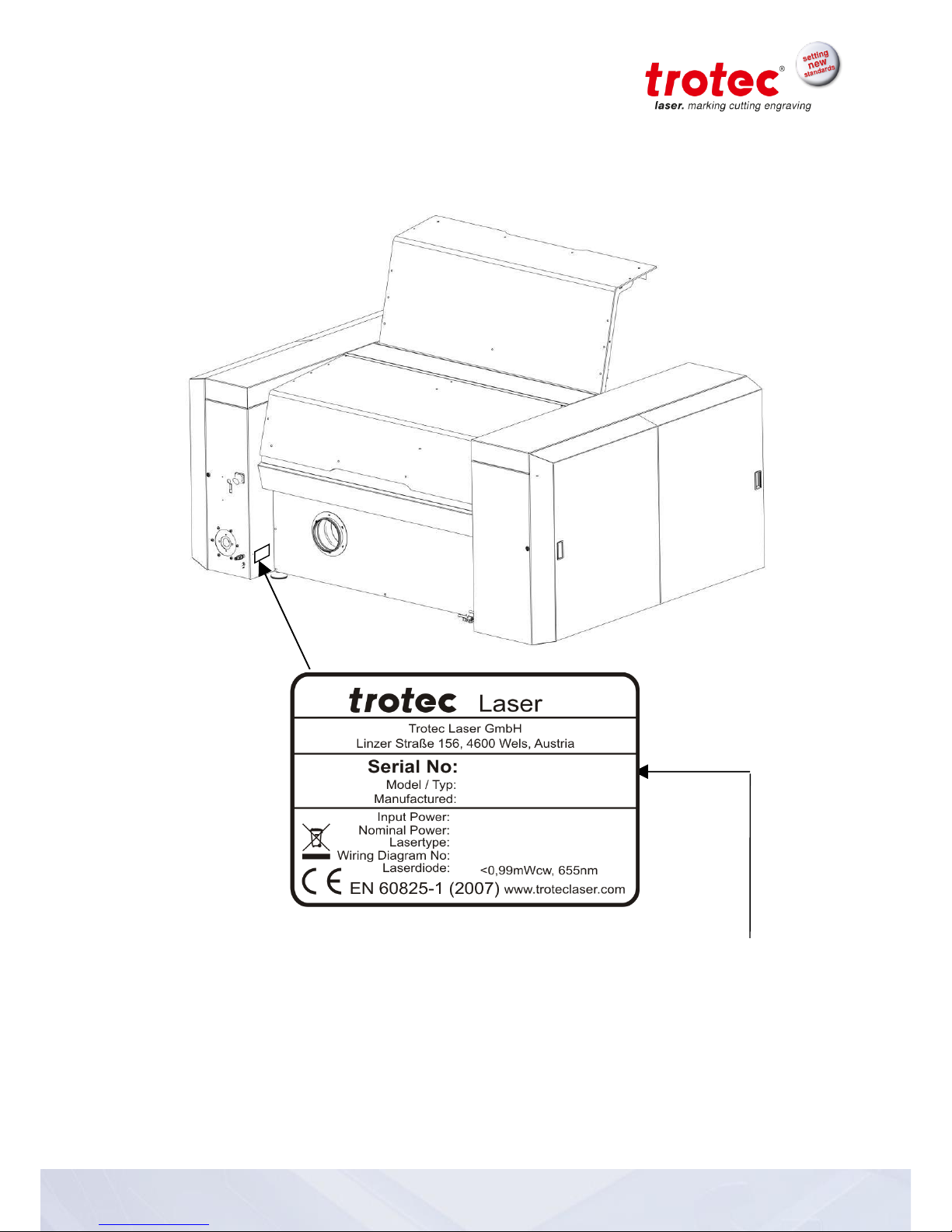
1 Manufacturing label
You find the manufacturing label with the CE-sign on the back side of the machine.
Enter the serial number, model and year of manufacture from the manufacturing label here.
This information is important for troubleshooting problems with the product and for ordering
replacement parts.
Page 6
6 / 53 8018_SP1500 V2.2_EN (03/2018)
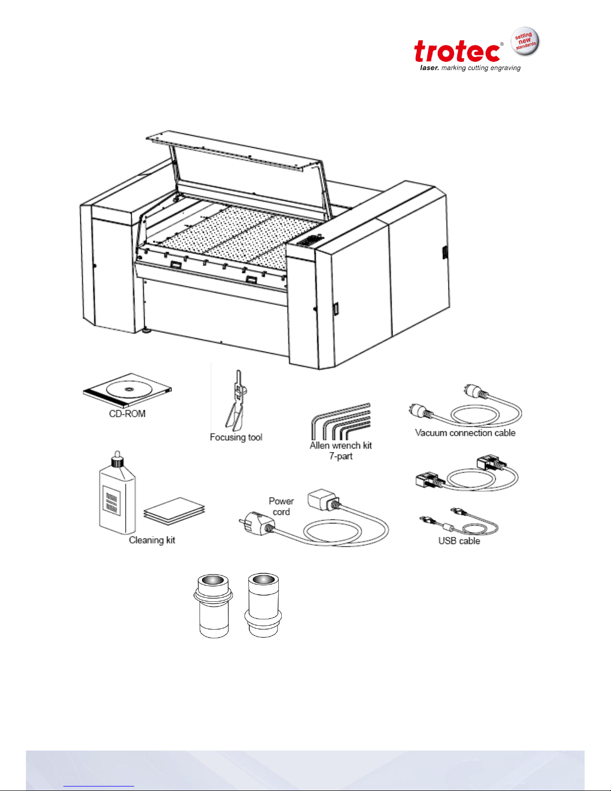
2 Product Components
Lenses 2.5“ / 5“
(7.5“ optional)
RS232-cable (TroCAM / i-Cut)
Page 7

7 / 53 8018_SP1500 V2.2_EN (03/2018)
3 Preface
3.1 General
This operating manual is intended to simplify the following for you:
Learning about the machine, and
Utilizing the machine’s capabilities according to its
intended use.
The operating manual contains important notes on how to operate
the machine:
Safely,
Properly, and
Economically
Following the operating instructions helps you to:
Avoid hazards and risks,
Minimize repair costs and downtimes, and
Increase the reliability and service life of your machine.
Page 8

8 / 53 8018_SP1500 V2.2_EN (03/2018)
3.2 Product Tracking
We have a legal duty to track our products after delivery to our
customers.
In particular, this relates to:
Recurring faults in functions
Anything that is unclear, e.g. in operation, maintenance
or instructions
Any accidents that occur
Other unusual observations
Recommendations for improvement, requests
This information serves as a basis for potential corrections and/or
changes to the product, and it is therefore of great interest to us.
We request that you inform us of any such events and offer us
your recommendations. This is the only way that we can improve
our products as necessary, and to make them as safe and reliable
as possible.
Page 9

9 / 53 8018_SP1500 V2.2_EN (03/2018)
4 Technical Data
4.1 General Description
All electronic components are integrated in the machine.
All necessary connections are made on the back side of the SP1500.
Controls for the SP1500 are located on the keypad.
The SP1500 is equipped with an interlock safety system. When
the interlock is activated, only setup tasks can be performed on the
SP1500.
The machine has a manual table changing system that enables use of the
optimal table for specific jobs.
4.2 Intended Use
The Trotec SP1500 is designed for engraving and cutting of the
materials listed in this document.
Page 10

10 / 53 8018_SP1500 V2.2_EN (03/2018)
4.3 Dimensions
Weight – depends on product model ............... 1200 - 1300kg
(2646 - 2867 lbs)
Item
Description
Dimension
Units
A
Length
2829 (112)
mm (inch)
B
Width
2197 (87)
mm (inch)
C
Height, closed
1293 (51)
mm (inch)
D
Height, open
1950 (77)
mm (inch)
C
D
B
A
Page 11

11 / 53 8018_SP1500 V2.2_EN (03/2018)
4.4 Mechanical Design
Working area
1500 x 1250 mm (59 x 49 in)
Feed area
1700 x 1600 mm (66 x 62 in)
Max. height of work piece
30 / 53 / 75 mm (1.18 / 2.08 / 2.95 in)
(3 work table levels)
185 mm (7.28 in) without work table
(flatness cannot be guaranteed without work table)
Speed of motion system
165 cm/s (65 in/sec)
Acceleration
9,55 m/s² (375 in/sec²)
Motor
Brushless DC servomotor
Encoder
Increment measuring system
Lenses
2,5“ and 5.0” (Standard), 7.5” (optional)
Lenses and all reflective mirrors are air-flushed and
therefore protected from soiling (preinstalled air pump)
Max. area load of workpiece
table
25 kg (55 lbs) over entire working area
Precision
±0,1 mm (±0.004 inch) over entire working
area
(depends on material)
Repeatability
< ±15 µm
(< ±0.00059 inch)
4.5 Control System
Laser power
Adjustable 0 – 100% (Typically 10-100%)
Hardware Interface
USB, RS-232 (RS-232 mandatory for TroCAM and i-Cut)
Software Interface
ASCII, HPGL, Trotec Protocol
4.6 Laser Tubes
Laser tubes
Sealed off CO2 laser, maintenance free,
Laser power of 60-400W
Wavelength
10,6 µm
Page 12

12 / 53 8018_SP1500 V2.2_EN (03/2018)
4.7 Laser Safety
Laser class
CDRH Laser Safety; CE tested
Laser class 2
Interlock
Dual interlock safety system
4.8 Ambient Conditions
Prescribed ambient temperature of +15° to +25°C (+59° to +77°F)
Humidity of 40% to max. 70%, no condensation,
dust-free environment (2nd degree per IEC60947-1)
4.9 Options
CCD-camera
Registration marks and compensation system „i-Cut“;
max. working area: 1100 x 700 mm (43 x 27.5 in)
Gas-Kit (for compressed air
respectively process gas)
Considered for control of compressed air and process
gas (free of mechanical dust, water and oil) max. flow
rate 150 l/min (40 gpm) with max. 10 bar (145 psi) max.
limit 4 bar on working head push fitting connection with
out diameter) connection on the machine with hose out
diameter of 6mm (0.23 in) resp. standard fitting for
compressed air.
Vacuum table
Strong vacuum effect for thin or corrugated materials
(3500 m³/h at 500 Pa)
TroCAM
(refer to TroCAM brochure)
CAD / CAM software for perfect cutting results;
inclusively nesting-function, lead-in/lead-out, tool paths
Extraction System lead /followup time
Lead- and follow-up time fully adjustable
Page 13

13 / 53 8018_SP1500 V2.2_EN (03/2018)
4.10 Electrical Connection
4.10.1 Electrical connection for laser system
Laserpower
60 W
100 W
200 W
400 W
Voltage
208/230 V,
1 phase
208/230 V,
1 phase
380/400 V,
3 phases
380/400 V,
3 phases
Fuse
16 A, slow
20 A, slow
3 x 20 A, slow
3 x 25 A, slow
Frequency
50/60 Hz
50/60 Hz
50/60 Hz
50/60 Hz
Phases
L, N, PE
L , N, PE
L1, L2, L3, N, PE
L1,L2,L3,N, PE
Power
2,6 kW
3,5 kW
5,5 kW
9,5 kW
4.10.2 Electrical connection for water cooling (option)
EU
Laserpower
60 W
100 W
200 W
400 W
Required refrigerating capacity [W]
500
2300
4000
8000
Chiller type
Chilly 08-S
Chilly 25-S
Chilly 45-S
CWK 90-S
Refrigerating capacity [W]
890
2400
5300
9500
Rate of flow l/min
7,2
10
16
30
Pressure in bar
2,9
2,7
3,5
3,4
Supply voltage
1x230V
50/60Hz
1x230V
50/60Hz
1x230V
50Hz
3x400V
50/60Hz
Power Requirement
900
1800
3000
5900
Supply voltage
L, N, PE
L, N, PE
L, N, PE
L1, L2, L3,
N, PE
US
Laserpower
60 W
100 W
200 W
400 W
Required refrigerating capacity [W]
500
2300
4000
8000
Chiller type
Chilly 08-S
Chilly 25-S
Chilly 35-S
CWK 90-S
Refrigerating capacity [W]
890
2400
4500
11000
Rate of flow l/min
8
10
15,2
36
Pressure in bar
3,7
3,5
3,7
4,8
Supply voltage
1x115V
60Hz
1x115V
60Hz
1x230V
50/60Hz
3x400V
50/60Hz
Power Requirement
900
1800
3000
5900
Supply voltage
L, N, PE
L, N, PE
L, N, PE
L1, L2, L3,N,
PE
Page 14

14 / 53 8018_SP1500 V2.2_EN (03/2018)
4.11 Materials
Caution when processing conductive materials (carbon fibers,…)! Conductive
dust or particles in the ambient air might damage electrical components and lead
to short circuits.
Bear in mind that those defects are NOT warranted.
Material
Engraving
Cutting
Marking
Acrylic
● ●
Painted metal
●
Delrin
● ●
Stainless steel (with Thermark)
●
Anodized aluminum
●
Veneer
● ●
Handicrafts
● ●
Glass
●
Wood
● ●
Gum rubber
● ●
Ceramic
● ●
Cork
● ●
Plastics
● ●
Laser rubber
●
Leather
● ●
MDF
●
Melamine
● ●
Micro porous rubber
● ●
Paper
● ●
Polyester
● ●
Stone
●
PC (Polycarbonate)
● ●
Other materials only with written approval by Trotec
The following materials are not recommended for processing:
Polyurethane PUR, Polyvinyl chloride PVC, Polyvinyl butyral PVB, Polytetrafluorethylene PTFE
and materials containing epoxy or phenolic resins
Caution:
Trotec assumes no responsibility for any consequences of laser processing in any
application such as medical or pharmaceutical applications.
Page 15
15 / 53 8018_SP1500 V2.2_EN (03/2018)
5 Safety
5.1 Safety Instructions
Operating personnel must read and understand the operating instructions, and especially the
“Safety” chapter, before operating the equipment. We recommend that the operator create internal
instructional documentation for equipment safety and operation and to acknowledge receipt of
these instructions/operating manual and participation in training/education in writing (see
documents in the Appendices)
1.1 Intended user group
The machine may only be operated by authorized persons.
Authorities must be clearly defined and observed, so that no unclear competencies result under the
aspect of safety. This applies in particular to work performed on the electrical equipment that may
only be performed by specially trained professionals.
Activity
Intended group of users
Control/operation
Trained personnel
Other activities
(e.g. error correction, maintenance)
Specially trained personnel or
hired tradesmen
1.2 Operating instructions / Safety equipment
The safety zone is defined by the operator. Instructions and guidelines must be observed and
followed!
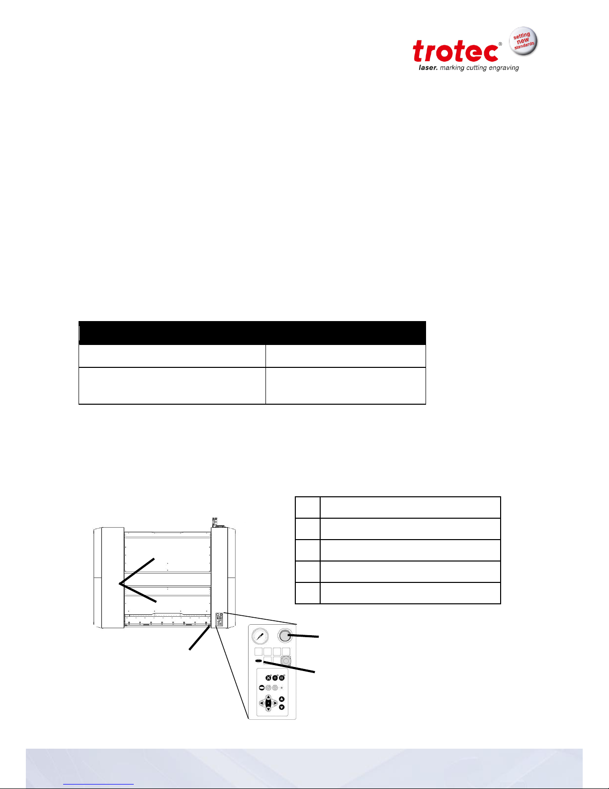
Top view
No.
Description
1
EMERGENCY-OFF pushbutton
2
Key switch
3
ON-OFF switch
4
Safety covers
1
2 4 3
Page 16

16 / 53 8018_SP1500 V2.2_EN (03/2018)
5.2 General Safety Instructions
2.1 General
Hazard due to improper use of the machine!
Improper use may lead to hazards and bodily injury and damage to assets.
Prohibit or prevent improper use.
Hazard due to disregard of safety instructions!
Improper activities at the machine may lead to death, bodily injury and/or damage
to the machine.
Before startup read and observe the operating manual and safety
instructions!
Hazard due to faulty behavior by untrained persons!
Improper activities at the machine may lead to death, bodily injury and/or damage
to the machine.
Inform personnel about machine functions and potential risks and
record this in the training record.
Observe legal regulations related to operation of machines and
accident prevention regulations.
Hazard due to poor lighting, poor housekeeping and moisture!
Shadows, reflections and poor housekeeping increase the risk of an accident.
Light the work area well, and always keep it clean and dry.
Hazard due to missing, defective or bypassed safety equipment or machine
parts!
Nonfunctioning or missing safety equipment or machine parts may lead to death,
bodily injury and/or damage to the machine.
Carefully check safety equipment and machine parts for proper
operation.
In case of a functional fault or defect, immediately take prescribed
actions to correct the problem
.
Hazard due to operator error (especially in setup mode)!
Adjustment and control with insufficient knowledge of the machine may lead to
death, bodily injury and/or damage to the machine.
Before startup read and observe the operating manual and safety
instructions!
Hazard due to unsupervised operation of the machine!
Unsupervised operation may lead to fire resulting in death, bodily injury and/or
damage to the machine.
Never operate the machine without supervision!
Page 17

17 / 53 8018_SP1500 V2.2_EN (03/2018)
Hazard due to reckless actions!
Reckless actions may lead to death, bodily injury and/or damage to the machine.
Make sure that no personnel remain in the hazardous area or at the
machine.
Do not leave any foreign objects in the machine (tools, etc.).
Hazard due to operator error by unauthorized persons!
Adjustment and control of the machine by persons with inadequate knowledge of
machine operation may lead to death, bodily injury and/or damage to the
machine.
Never inadvertently actuate the machine.
Turn the main switch off when the machine is not being used.
Hazard during faulty work process!
Deviations in machine processing and work results may be an indication of
hazardous conditions (jammed product, loose guides, etc.).
Observe machine movements for proper operation and check work
results on a regular basis.
In case of deviations, initiate prescribed actions.
Hazard due to premature actuation!
Premature actuation of the machine may lead to death, bodily injury and/or
damage to the machine.
Do not reach into hazardous areas until you have turned off the
main switch and placed a service sign on it.
Hazard due to inadequate cleaning or functional checks!
Inadequate cleaning or functional checks result in machine damage.
Accumulation of dirt could impair mechanical functions.
Regularly check machine and connection lines for damage and
wear. In case of damage, immediately initiate prescribed actions.
Keep machine, handles and switches free of oil, grease, dirt and
moisture.
Hazard due to unsuitable tools!
The use of improper tools could result in a risk of bodily damage and/or damage
to the machine. Poor housekeeping leads to elevated accident risk.
Use proper tools for maintenance jobs.
Page 18

18 / 53 8018_SP1500 V2.2_EN (03/2018)
Hazard due to missing machine signage!
The risk of machine operator error results from making incorrect assumptions.
Replace missing machine signage.
Hazard due to fault that cannot be corrected!
A fault that cannot be corrected may lead to injury and/or damage to the
machine.
Turn off the machine and call customer service!
Hazard due to improper disposal (waste, production materials)!
Improper disposal of waste materials can lead to environmental damage.
Recycle recyclable materials in separated and clean state. Dispose
of waste in accordance
with applicable legal regulations.
Hazard due to inferior replacement parts or parts from other companies!
The use of inferior replacement parts or parts from other companies impairs
machine safety and invalidates the supplied Conformity Declaration (CE).
Replace wear parts or damaged machine, safety or electrical
components with original replacement parts. Only use the
accessories or auxiliary
devices identified in the operating manual.
Hazard due to unsuitable work clothing or lack of protective equipment!
Risk of injury due to catching on machine parts, falling loads, inhalation of dust
particles
and noise.
Wear suitable work clothing.
Wear safety glasses.
Wear hearing protection (mandatory for noise levels >85 dB(A))
Page 19

19 / 53 8018_SP1500 V2.2_EN (03/2018)
2.2 Laser
The machine is:
- Safety class 2
Hazard due to laser radiation without protective measures!
Lack of protective measures can result in:
- Burns on the corneas of the eyes,
- Skin burns, and
- Fire hazard for clothing
Never operate machine without protective equipment
Unapproved modification or disassembly of the laser is prohibited
Never manipulate the laser unit
Do not bypass the interlock system
Hazard in processing unapproved material!
Processing of materials not listed and approved in this operating manual is
prohibited.
Processing medical technology and pharmaceutical products!
Trotec assumes no responsibility for any consequences or the suitability of laser
processing for any applications, especially those in the medical technology or
pharmaceutical fields.
Hazard when working with the cutting table!
If not all of the partition plates are used in the cutting table, there is a risk of fire
due to reflection of the laser beam.
Insert anti-reflective material beneath the partition plates.
Page 20

20 / 53 8018_SP1500 V2.2_EN (03/2018)
2.3 Transport
Hazard of loads impacting persons or objects!
Falling, tipping or sliding loads may lead to death, bodily injury and/or damage to
the machine.
Never let loads impact persons.
Set up unloading station before lifting loads. Avoid unnecessarily
long periods of lifting.
Do not lift loads until you have a clear view of the travel route.
Choose travel routes that are as unobstructed as possible.
Hazard due to lifting equipment operator error by untrained personnel!
Improper operation of lifting equipment may lead to death, bodily injury and/or
damage to the machine.
Operation of lifting equipment only by trained personnel.
Wear protective helmet, safety shoes and gloves.
Page 21

21 / 53 8018_SP1500 V2.2_EN (03/2018)
5.3 Secondary Risks
3.1 General
Hazard due to materials hazardous to health!
In processing with or use (cleaning, etc.) of hazardous materials
(toxic, etc.), appropriate measures should be taken to avoid health
hazards.
Hazard due to operator error!
Errors are possible even when the machine is operated properly following the
functions and sequences described in the operating manual. Such errors may
lead to death, bodily injury and/or damage to the machine.
Do not initiate any work or adjustment activities while any
personnel are located in the hazardous area.
Hazard due to add -on options or machines!
Adding on options or machines can lead to unknown risks and hazards.
Modifications made to the machine without approval by Trotec
invalidates the Conformity Declaration (CE) supplied with the
product.
3.2 Crushing hazard
Hazard due to moving parts!
Reaching, stepping or leaning into the hazardous area may result in serious
injury by crushing body parts, severing fingers or the hand!
Do not initiate any work process on the machine while persons
(helpers, etc.) are located in the hazardous area of the machine.
Prohibit access to the hazardous area.
Wear suitable work clothing (no loose clothing, jewellery, or
similar.).
Page 22

22 / 53 8018_SP1500 V2.2_EN (03/2018)
5.4 Signage
The warning and information labels are attached in such positions of the device that
could represent a source of danger during set-up and operation. Therefore, follow the
information on the labels. If labels are lost or damaged, they must be replaced
immediately.
Nr.
Label
Position
(see also pictures on the next page)
1
a) External: frontside top cover, left side
b) External: backside top cover, right side
c) External: maintenance panel front locker
d) External: maintenance panel back locker
e) External: next to service plug
2
a) External: at control panel
b) Internal: maintenance panel at the top
3
a) External: frontside top cover, left side
b) External: backside top cover, right side
c) External: maintenance panel front locker
d) External: maintenance panel back locker
4
a) Internal: working area, at x-axis left side
b) Internal: maintenance panel at laser diode
5 External: at control panel
6 Internal: maintenance panel at the top
7 External: next to the power socket
8
a) External: service panel front locker
b) External: service panel back locker
c) Internal: service panel, cover of electronics
9
External: at the front cover, right side
10
a) External: at control panel
b) Internal: working area, at x-axis left side
c) External: maintenance panel front locker
d) External: maintenance panel back locker
e) Internal: at mirror 1
f) Internal: at laser diode (mirror 2)
11 a) External: next to the power socket
b) External: service panel front locker
c) External: service panel back locker
NEVER OPERATE THE LASER SYSTEM
WITHOUT CONSTANT SUPERVISION
EXPOSURE TO THE LASER BEAM MAY
CAUSE IGNITION OF COMBUSTIBLE
MATERIALS WHICH CAN CAUSE
SEVERE DAMAGE TO THE EQUIPMENT
LASER RADIATION
DO NOT STARE INTO THE BEAM
CLASS 2 LASER PRODUCT
BEFORE OPEN UNPLUG THE
MACHINE FIRST
INPUT POWER
380-400VAC 50HZ
CO2 laser
Power Range 40-400 W
Wavelength 10600 nm
LASER APERTURE
CAUTION
CLASS 2 LASER RADIATION WHEN
OPEN DO NOT STARE INTO BEAM
LASERDIODE
MAX. POWER < 1mW cw
WAVELENGTH 655nm
CAUTION
CLASS 4 INVISIBLE LASER RADIATION
WHEN OPEN AND INTERLOCKS
DEFEATED
AVOID EYE OR SKIN EXPOSURE TO
DIRECT OR SCATTERED RADIATION
Page 23

23 / 53 8018_SP1500 V2.2_EN (03/2018)
Front and right side
Back and left side
8 9 2, 5, 10
1, 3
1
8, 11
1, 3, 10
4, 10
2, 6
10
(position depends
on laser type)
4, 10
(position depends
on laser type)
1, 3, 10
8, 11
7, 11
1, 3
Page 24

24 / 53 8018_SP1500 V2.2_EN (03/2018)
6 Transport - Storage - Setup
6.1 Forklift transport
You receive your SP1500 packed in a wooden crate. If possible keep the packing box. You might
require it in case of a return.
1. Remove the top cover of the wooden box. Then the side covers. For this work we strongly
recommend to use an electric screwdriver.
SP1500 kept in position by wooden spacers
Please note that the machine housing is reinforced only on certain positions so that a fork lift truck
can lift the machine.
The following suspension points are
available:
- machine front and back
- left and right side
These positions are marked. See also the
yellow colored bars besides (bottom
view).
Never place the forks on other positions,
as this could cause severe damages on
the housing and affect cutting precision
as well as life expectancy of the motion
system.
The machine may only be lifted and
transported:
- under the guidance of a 2nd person
- at the marked points
- with a fork lift carrying 2000kg (4.4 lb)
and
- forks of minimum 2m length
Page 25

25 / 53 8018_SP1500 V2.2_EN (03/2018)
2. Carefully lift the machine from the box floor.
3. Position the SP1500 on an even floor capable of carrying the machine weight. This location
must meet the ambient requirements mentioned below.
Page 26

26 / 53 8018_SP1500 V2.2_EN (03/2018)
6.2 Shipping conditions
- When transporting outdoors, only transport in shipping vehicles
with roofs or sufficient weather protection.
- Protect machine from shipping damage using tie-down straps,
packaging materials and sufficient gaps to other shipped goods.
- Ambient temperature for transport:
Minimum temperature +10 °C (+50 F)
Maximum temperature +40 °C (+104 F)
- Handle machine and machine parts with care.
- Do not place any heavy loads on top of the machine or machine parts.
- Avoid harsh impacts.
- Only lift at the specified points.
- Take special care in transporting electronic components.
6.3 Unloading, inspection and damage reporting
After unloading:
- Remove shipping packaging.
- Dispose of packaging according to applicable waste disposal law.
- Inspect machine and machine parts for shipping damage.
- Check shipment for completeness.
In case of shipping damage or incomplete shipment:
- Immediately document the details of the damage.
- Also note the claim on shipping papers.
- Photograph the damage.
- Send report to Trotec.
6.4 Storage conditions
- Store machine and machine parts in a dry area.
- Protect machine and machine parts from scratches.
- Store electronic components especially carefully in a packaged state.
- In case of longer term storage, protect exposed metal parts
(e.g. oil the parts).
- Ambient temperature for storage:
Minimum temperature +10 °C (+50 F)
Maximum temperature +40 °C (+104 F)
6.5 Storage Location
In storage room or packaged with adequate weather protection.
The storage location must be free of caustic materials, vapors and
combustible materials.
Page 27

27 / 53 8018_SP1500 V2.2_EN (03/2018)
6.6 Installation Site
- Weather-protected, roofed building with vehicular access
- Low dust environment
Properties of the installation site:
- Adequate lighting
- Uniform, level, horizontal and firm floor, planarity +/-5 mm
(+/-0.1969 inch), no special foundation required
- Load bearing capacity of base frame at least 500 kg/m2
(105 lbs/sq.ft.)
Installation site must:
- Be free of noisy electrical installations, hoses and pipe lines
- Have power supply that is free of fluctuations
- Be shielded from EMC
Ambient Conditions:
- Relative humidity: 40% to max. 70%
- Ideal room temperature: +15°C to +25°C (+59 F to +77F)
- Dust-free environment (2nd degree per IEC60947-1)
6.7 Space Requirements
6.8 Necessary Feed Lines
- Electrical
- Compressed air: Free of oil, water and dirt at max. 10 bar (145 psi)
- Gases (Neutrogen, Argon, protective gas, …)
1500 mm
1500 mm
1500 mm
1500 mm
Page 28

28 / 53 8018_SP1500 V2.2_EN (03/2018)
6.9 Setup
Align machine to horizontal level by adjusting the feet, and check with a water level. Measure the
level on the x-axis and y-axis.
For the adjustment of the feet a 24mm wrench is necessary.
Page 29

29 / 53 8018_SP1500 V2.2_EN (03/2018)
6.10 Connections
Item
Description
Item
Description
1
Electrical power
6
Cooling water connectors
2
Connection cable exhaust system
7
Compressed air (Gas 1 – standard
connector)
3
RS-232 for PC
(mandatory for i-Cut/AlphaCam)
8
Gas 2
4
USB for PC
9
Table exhaust connector (200mm)
5
Head exhaust connector
1
2
3 4 5 6 7 8 9
Page 30

30 / 53 8018_SP1500 V2.2_EN (03/2018)
6.10.1 Cooling System
Note: It’s important to connect the “water in” of the SP1500 with the “water out” of the chiller, and
the “water out” of the SP1500 with the “water in” of the chiller.
1. Start the chiller.
2. Start the laser machine (note order!).
Sketch of Chillers
for Laser Power 60W to 200W:
Sketch of Chiller
for Laser Power 400W:
Page 31

31 / 53 8018_SP1500 V2.2_EN (03/2018)
7 Machine view
Item
Description
Item
Description
1
Working head
6
Main switch
2
X-Axis
7
Top Cover
3
Working table
8
Keypad
4
Removal door for leavings / waste
9
Service Panel
5
Maintenance panel
1 2 3 4 7
8 6 5
9
Page 32

32 / 53 8018_SP1500 V2.2_EN (03/2018)
8 Operation
8.1 Key pad – Overview
Item
Description
Item
Description
1
Key switch
13
Button: Start (repeat) - JobControl only
2
EMERG. OFF push button
14
Button: “Shift” for 2nd function key level
3
Indicator: Interlock on/off
15
LED status indicator: Laser beam
4
Indicator: Cooling on/off
16
Button: Working head to left
5
Button: Compressed Air (Gas 1)
17
Button: Working head to right
6
Button: Gas 2
18
Button: Working head forward
7
Air assist (internal)
19
Button: Working head backward
8
Light: compressed air, Voltage (AC, DC)
20
Not used
9
Button: Vacuum on/off
21
Not used
10
Button: Standby
22
LED status indicator
11
Button: Pause
23
Manometer for gas pressure
12
Service LED
24
Pressure regulator
Page 33

33 / 53 8018_SP1500 V2.2_EN (03/2018)
8.2 Key pad – Description
Key switch (1)
EMERGENCY OFF pushbutton (2)
Pressing this button shuts the machine down completely.
The EMERGENCY OFF pushbutton must be unlocked to start up the
machine again.
Interlock on/off indicator (3)
Interlock indicator lights when the machine is turned on, and:
- Guard door or door is open
- Cover plate is not installed
If the Interlock Indicator is unlit, the machine is ready for production.
Cooling on/off indicator (4)
Switching-in process gas
- Compressed Air (Gas 1) on/off key (5)
- Gas 2 on/off key (6)
Pressure regulator (24)
This is used to adjust the required gas pressure of the gas used. The
pressure setting is displayed on the:
Manometer for gas pressure (23)
Air assist on/off indicator (7)
Air assist is switched on/off by simultaneously pressing these keys:
“Shift” for 2nd function key level (14)
and
Vacuum on/off (9)
Compressed air, voltage (AC, DC) (8)
Lights in following conditions:
- Compressed air missing
- AC-Voltage failure (L1, L2, L3, N)
- DC-Voltage failure (power supplies)
Page 34

34 / 53 8018_SP1500 V2.2_EN (03/2018)
Vacuum on/off key
(9)
When this key is pressed it lights and vacuum is
switched on for the vacuum table
Standby key
(10)
During machine operation key illumination is off.
When the key is pressed it lights and the machine is in
Standby mode, i.e.:
- Laser in Ready state
- Lighting of work table is deactivated
- Blowers for laser tubes are deactivated
Pause key
(11)
During machine operation key illumination is off.
When the key is pressed it lights and the work process being
executed is stopped
Lamp for service plug
(12)
Lights when a service plug is inserted (Technician)
Start (Repeat) key
(13)
Key for starting the job program and repeating the last job
program; see programming manual regarding this
“Shift” key for 2nd function key level
(14)
For additional operations. When this key is pressed
together with the following keys, the functions indicated
are
activated:
Vacuum on/off key
(9):
Air assist on/off
Pause key
(11):
Stops the job program
Working head keys
(16) to (19)
These keys drive the laser head to the end
position (left/backwards)
Start key
(13):
Tests the laser for proper function
LED status indicator for laser beam
(15)
Lightened when laser is operating
Page 35

35 / 53 8018_SP1500 V2.2_EN (03/2018)
Movements of the laser head:
- Key: Working head to left (16)
- Key: Working head to right (17)
- Key: Working head forward (18)
- Key: Working head backward (19)
When 2 adjacent keys are pressed simultaneously
(e.g. keys 16 and 19), the laser head moves diagonally.
Movements of the work table (20, 21):
Not used on SP1500
LED status indicator
(22)
- Flashes 1x/sec -> Machine ready for operation
- Flashes 2x/sec -> Interlock ON
Page 36

36 / 53 8018_SP1500 V2.2_EN (03/2018)
8.3 Workpiece Removal Door
Open door by turning the lock (1) and pulling
forward on the two handles
CAUTION door is HEAVY
Remove the waste or workpieces
Door must be closed during
laser operation.
1
Page 37

37 / 53 8018_SP1500 V2.2_EN (03/2018)
8.4 Tables
8.4.1 Cutting Table (Standard Table)
8.4.2 Vacuum Table
The vacuum table is only intended for engraving
and/or cutting thin and lightweight materials such
as films, plastic laminates, veneers, thin sheets
of wood, paper, cardboard, and similar.
The entire surface of the vacuum table must
be covered to ensure the maximum vacuum
effect
Page 38

38 / 53 8018_SP1500 V2.2_EN (03/2018)
8.5 Operation
Enable machine with the key switch (1)
Check whether EMERGENCY-OFF pushbutton
(2)
is unlocked (pull to release)
Turn on main switch (3)
Wait until reference movement is finished
(covers have to be closed)
Drive the laser head to its forward-end
position and drive it upward with the adjusting
screw (4)
Clean lens, reinstall and secure
Install nozzle
Carefully place material on table
Focussing the laser
Place focus tool on laser head
Drive the working head downward until focus tool drops
out.
Machine is now ready for production.
4
5
Page 39

39 / 53 8018_SP1500 V2.2_EN (03/2018)
8.6 Changing the lens
Use disposable gloves to avoid direct contact with the optics.
Overview
1. Turn the laserhead all the way down to
allow enough space.
2. If necessary, reduce the distance from
the nozzle to the material to move even
further down.
2,5'' Cylinder
5'' Cylinder
Focus tool for 5'' lens
Focus tool for 2,5'' lens
Outer cylinder
Page 40

40 / 53 8018_SP1500 V2.2_EN (03/2018)
3. Loosen the two screws to remove the
cylinder.
4. Loosen the cylinder by turning.
5. Remove both cylinders together from
the laser head (outer and inner cylinder
- see overview).
6. Lay the outer cylinder aside.
Page 41

41 / 53 8018_SP1500 V2.2_EN (03/2018)
7. Loosen the lens holder by turning and
carefully remove the lens.
8. Put the lens on a cleaning cloth.
Clean the lens on both sides with the
cleaning fluid and wipes.
Check lens for cleanliness and
damage.
9. Put the lens correctly in the socket.
Put the curvature or convex
side of the lens upwards.
10. Screw the socket on the cylinder again.
Page 42

42 / 53 8018_SP1500 V2.2_EN (03/2018)
11. Put the cylinder back into the
laserhead and screw it in.
If both cylinders are not
concentrically fixed over the
thread, the lower cylinder
cannot be screwed into the
thread.
12. Tighten the two previously loosened
screws securing the upper cylinder.
Page 43

43 / 53 8018_SP1500 V2.2_EN (03/2018)
13. Screw the laserhead back in the Z-
direction.
14. Focus with the corresponding focus
tool and adjust the distance to the
nozzle to the material surface (approx.
1 cm by default).
Page 44

44 / 53 8018_SP1500 V2.2_EN (03/2018)
9 Maintenance
9.1 Cleaning optics on the Laser Head
Cleaning the mirror (1):
Loosen and remove both screws (2)
Remove mirror holder (3)
Check mirror (1) for damage
Clean mirror (1) with cleaning fluid
and cleaning cloth
Check mirror (1) for damage once again
Reinstall mirror holder (3) and secure with
two screws (2)
Cleaning lenses
Loosen the two screws (4) holding the upper
cylinder (5)
Loosen the lower cylinder (6) by screwing it inward
Remove both cylinders together
Loosen lens holder (7) and remove lens
Check lens for damage
Clean both sides of lens with Cleaning fluid and
cleaning cloth
Check lens once again for damage
Insert and fix lens in the reverse order (CAUTION:
round side of lens has to face laser source)
5“ 7"
2.5“
7
7
4 6 5
Page 45

45 / 53 8018_SP1500 V2.2_EN (03/2018)
9.2 Cleaning the Mirrors
Unlock cover (1)
- Tool: Metric Allen wrench No. 10 (6)
Remove cover (1) by pulling on the handles (7)
3 mirrors (2) must be cleaned:
Loosen both screws (3)
Remove mirror holder (4)
Check mirror (5) for damage
Clean mirror (5) with Cleaning fluid and
cleaning cloth
Check mirror (5) once again for damage
Put on mirror holder (4) and secure with
two screws (3)
1
2
2
6
7
Page 46

46 / 53 8018_SP1500 V2.2_EN (03/2018)
9.3 Cleaning the Exhaust hose connector
Back view:
Clean the head and table hose connector with a vacuum cleaner or a suitable brush regularly.
Check the protective grid weekly and optionally remove the deposits and clean the grid to ensure a
good extraction.
Risk of fire by depostis
Deposits in the exhaust hose connections may occur flame formations.
- Check and clean the hose connections and the protective grid regularly.
- Comply with the maintenance plan!
Item
Description
1
Head exhaust connector
2
Table exhaust connector
1
2
Page 47

47 / 53 8018_SP1500 V2.2_EN (03/2018)
9.4 Maintenance plan
daily
weekly
monthly
yearly
Laser
Lens, mirror #4
Check
Cleaning if
required
mirrors #1...3
Check
Cleaning if
required
Processing table and
rulers
Cleaning
Exhaust hose
connections
Check
Cleaning if
required
Protective grid
Check
Cleaning if
required
Entire working area –
general cleaning
Cleaning
Exhaust System
Bag filter
According to the operation manual
of the exhaust system
Filter mat
Particle filter
Activated carbon filter
Cooling System
Pump filter
According to the operation manual
of the exhaust system
Condenser heater
Cooling agent
Pump
For detailed information on the maintenance activities on exhaust and cooling systems
please refer to the respective manuals.
Page 48

48 / 53 8018_SP1500 V2.2_EN (03/2018)
10 Appendix
10.1 EU – Declaration of conformity
(Machine directive 2006/42/EG, appendix II A)
Manufacturer:
Trotec Laser GmbH
Linzer Straße 156,
A-4600 Wels
Authorized person for the compilation of technical documentation:
Gerhard KREMPL, Trotec Laser GmbH., Linzer Straße 156, A-4600 Wels
We hereby certify that
SP1500
Model N° 8018 SP1500
in its conception, construction and form put by us into circulation is in accordance with all the relevant
essential health and safety requirements of the EC machinery directive 2006/42/EEC.
Further valid guidelines/regulations for the product:
2006/95/EG Low Voltage Directive
2004/108/EG EMC Guideline
Applied harmonized standards:
- EN ISO12100 Machine Safety
- EN 60335-1/2007 Safety of Household and similar Appliances
- EN 55014-1/2006, EN 55014-2/1997 Electromagnetic Compatibility
- EN 60204-1 Machine Safety – electr. Equipment
- EN 60825-1/2007, EN 60825-4/2006 and EN 60825-14/2006 Safety of Laser Equipment
- EN 55022/2008, EN 55024/2003 Electromagnetic Compatibility
Place, Date:
Wels, 30.03.2011
Personal data of the signer:
Stephan FAZENY, Head of Research and Development
Signature:
Page 49

49 / 53 8018_SP1500 V2.2_EN (03/2018)
10.2 Acceptance report
Dear customer!
Please check applicable items:
We request your confirmation of
properly completed transfer of
the machine
Machine parts checked for shipping damage
Machine parts checked against delivery note
Setup of the machine discussed
Startup of the machine discussed
Operation of the machine discussed
Maintenance of the machine discussed
Electrical voltage checked
Safety Instructions discussed
Trial run performed
Deficiencies determined
The machine with the
Please transmit a copy of this
document – filled out and
signed by an authorized
company representative – to an
employee of our sales affiliate
for forwarding to the
manufacturer.
Thank you very much.
machine designation: SP1500
has been checked according to the listed items and has
been transferred properly.
City, Date
Company stamp / Signature
Page 50

50 / 53 8018_SP1500 V2.2_EN (03/2018)
10.3 Acceptance report
Employee/Trainee:
Trainer:
Date of Training:
The above mentioned Employee received instruction on the operation of the SP1500
Lasersystem.
Especially the following topics are covered:
- Machine Function
- Danger Area
- Warnings
- Position
Emergency-OFF
Button
- Personal Protective Equipment
- Operating Facilities
- Work Flow
- Setting-up
- Taking into Service and Shutdown
- Announcement of unexpected working result and the resulting procedure
- Announcement of Failure and instituting Procedure
- Responsibility on remedial measure
- Operation Manual and its depository for inspection
............................................................... ...............................................................
Signature of Trainer Signature of Trainee
Page 51

51 / 53 8018_SP1500 V2.2_EN (03/2018)
10.4 Response Form
If you face any trouble with the machine, please provide the following information and add a
Servicefile (procedure is described on the following pages).
Date
Machine Details
Contact Details
Serialnumber
Name
JobControl Version
Country
Driver Version
Phone Number
Layout Software
Email address
Firmware Version
Problem Description
Does an Error message show up on the PC, if so which one?
What happened before the error showed up? (Thunder&Lighing, Windows-Update,…)
What was tried to solve the problem?
Please send the information to your sales representative or to techsupport@troteclaser.com.
Page 52

52 / 53 8018_SP1500 V2.2_EN (03/2018)
10.5 How to create a Service File
1. Start JobControl.
2. Position the job (which possibly caused a failure) on the plate.
3. Run the job and leave the job on the plate.
4. Go to “Settings” > “Create Service File”.
5. The window „Save Service File to“ shows up. Please select a directory to save the file and
click on „Save“.
Page 53

53 / 53 8018_SP1500 V2.2_EN (03/2018)
6. The window „Add Layout File“ shows up. Please select the layout file, which was sent most
recently to JobControl and possibly caused a failure (example: Corel file, Photoshop file,
AutoCAD file,…). Click on „Open“.
7. The following window confirms, that the Service File (ServiceLog.txt) was created
successfully.
8. Please send the Service File together with a picture of the bad result and detailed
description to your sales representative or to techsupport@troteclaser.com.
 Loading...