

Page 1
EC Series
EN
Infrared Camera – Operating Manual . . . . . . . B - 1
TRT-EC060-HS-003-GB
TROTEC GmbH & Co. KG • Grebbener Straße 7 • D-52525 Heinsberg
Tel.: +49 2452 962-400 • Fax: +49 2452 962-200
www.trotec.de • E-Mail: info@trotec.de
Page 2

OVERVIEW OF CONTENTS
01. Read This First . . . . . . . . . . . . . . . . . . . .B - 02
02. Component Guide . . . . . . . . . . . . . . . . . . B - 04
Front View . . . . . . . . . . . . . . . . . . . . . . . . B - 04
Rear View . . . . . . . . . . . . . . . . . . . . . . . . . B - 04
Function keys/Docking station . . . . . . . . . B - 04
03. Preparing the IR Camera . . . . . . . . . . . .B - 05
Charging the Battery . . . . . . . . . . . . . . . . . B - 05
Inserting the Battery / SD Card . . . . . . . . . B - 05
Powering On/ Off . . . . . . . . . . . . . . . . . . . B - 06
Information on the LCD Monitor . . . . . . . B - 06
Information regarding the . . . . . . . . . . . . B - 06
operating indicator
Setting Time and Date . . . . . . . . . . . . . . . B - 07
Local Settings . . . . . . . . . . . . . . . . . . . . . . B - 07
04. Basic Functions . . . . . . . . . . . . . . . . . . . B - 08
Using the LCD Monitor . . . . . . . . . . . . . B - 08
Selecting Menus and Settings . . . . . . . . B - 08
Performing a Reset . . . . . . . . . . . . . . . B - 09
05. Measuring . . . . . . . . . . . . . . . . . . . . . . . . B - 09
Manual Focusing . . . . . . . . . . . . . . . . . B - 09
Thermal and Visual Images . . . . . . . . . . B - 09
DuoVision . . . . . . . . . . . . . . . . . . . . . B - 10
Image Only . . . . . . . . . . . . . . . . . . . . B - 10
Image Adjustment . . . . . . . . . . . . . . . . . . . B - 10
Automatic Setting . . . . . . . . . . . . . . . . . . . B - 10
Manual Setting . . . . . . . . . . . . . . . . . . . . . B - 10
Image Settings . . . . . . . . . . . . . . . . . . . . . B - 11
Measurement Range . . . . . . . . . . . . . . . . . B - 11
Freezing / Activating an Image . . . . . . . . . . B - 12
Setting Analysis Parameters . . . . . . . . . B - 12
Analysis Settings . . . . . . . . . . . . . . . . . . . B - 13
Spot Analysis . . . . . . . . . . . . . . . . . . . . . . B - 14
Area Analysis AREA . . . . . . . . . . . . . . . . . . B - 15
Professional Analysis PROFILE . . . . . . . . . B - 15
Moving the Analysis . . . . . . . . . . . . . . . . . B - 16
Deleting the Profile Analysis . . . . . . . . . . . B - 16
Isothermal Analysis . . . . . . . . . . . . . . . . . . B - 16
Removing Analysis Tools . . . . . . . . . . . . . . B - 16
Saving Images . . . . . . . . . . . . . . . . . . . . . B - 16
Voice Annotations . . . . . . . . . . . . . . . . B - 17
Trigger Settings . . . . . . . . . . . . . . . . . . . . B - 17
Trigger Information . . . . . . . . . . . . . . . . . . B - 17
06. Recording and Deleting . . . . . . . . . . . . . B - 17
Opening Images . . . . . . . . . . . . . . . . . . . . B - 17
Selecting Images . . . . . . . . . . . . . . . . . . . B - 17
Selecting the Name of the Current Folder . . . B - 18
Voice Annotations . . . . . . . . . . . . . . . . . . . B - 18
Deleting Images . . . . . . . . . . . . . . . . . . . . B - 18
07. Reading Out Images . . . . . . . . . . . . . . B - 19
Reading Out Images from the SD Card . . . B - 19
08. Connecting and Reading Out . . . . . .. . . . . B - 19
Charging via the Docking Station . . . . . . . B - 19
Connecting to a Monitor . . . . . . . . . . . . . . B - 19
Connecting to a Computer . . . . . . . . . . . . B - 19
Installing Drivers . . . . . . . . . . . . . . . . . . . . B - 20
Transferring Videos via USB . . . . . . . . . . . B - 20
- Troubleshooting . . . . . . . . . . . . . . . . . . . B - 21
- Using the Bluetooth Headset . . . . . . . . . . B - 22
09. Care and Maintenance . . . . . . . . . . . . B - 22
10. Troubleshooting . . . . . . . . . . . . . . . . B - 22
11. Emissivity Table . . . . . . . . . . . . . . . . B - 23
12. Technical Data . . . . . . . . . . . . . . . . . B - 25
This publication replaces all previous announcements. No part of this publication
may be reproduced, processed using electronic systems, replicated or distributed
in any form, without our written authorisation. Subject to technical changes. All
rights reserved. Names of goods are used without guarantee of free usage keeping to the manufacturer‘s syntax. The names of goods used are registered and
should be considered as such. We reserve the right to modify design in the interest of ongoing product improvement, such as sha pe and colour modifications.
The scope of delivery may vary from that in the product description. All due care
has been taken in compiling this document. We accept no liability for errors or
omissions. © TROTEC
®
B - 1
Infrared Camera – Operating Manual
EN
Page 3

01. READ THIS FIRST
Test Shots
Before you point your camera at any objects and start
measuring, we highly recommend that you shoot
several trial images to confirm that the IR camera is
operating and being operated correctly.
Please note that GSAT, its subsidiaries and affiliates
and its distributors are not liable for any consequential damages arising from any malfunction of an IR
camera or accessory that results in the failure of an
image to be recorded or to be recorded in a format
that is machine readable.
Warning Against Copyright Infringement
Safety Instructions
Before using the camera, please ensure that you read
and understand the safety instructions laid out below.
Always ensure that the IR camera is operated correctly.
The safety instructions on the following pages are
intended to instruct you in the safe and correct operation of your IR camera and its accessories in order
to prevent any injuries or damage to yourself or other
persons and equipment.
WARNING
Please read the following important instructions carefully:
- Risk of damage to eyesight
Do NOT point the laser at people or at
animals. This can result in severe da-
m
mage to the eyes !
- Disassembling the camera
Do NOT modify or disassemble the camera or any of
its parts other than described in this manual.
- Stop operating the camera immediately if it starts to
emit smoke or toxic fumes
Failure to do so may result in fire or electric shock.
Immediately turn off the power of the camera remove
thebattery from the camera or unplug the power
cord from the power outlet. Check to see that no more
smoke or fumes are coming out of the camera.
- Stop operating immediately you drop the camera or
damage the housing.
Failure to do so may result in fire or electric shock.
Immediately turn off the power of the camera, remo ve the battery from the camera or unplug the power
cord from the power outlet.
- Do not use substances containing alcohol, benzene,
thinners or other flammable substances to clean or
service the IR camera.
The use of these substances may cause a fire.
- Remove the power cord at regular intervals and wipe
away any dust and dirt that collects on the plug, around
the the power outlet and the surrounding area.
In dust-filled, humid or greasy environments, the
dust that collects around the plug over long peri ods of time may become saturated with humidity
and short-circuit and cause a fire.
- Do not grip or touch the power cord with wet hands.
If you grip or touch the power cord with wet hands,
you are in severe danger of receiving an electric
shock. Pull out the cord at the plug only. Do NOT tug
at the cord. If you pull out the plug by the cord, you
run a severe risk of damging the wires or insulation
which could in turn lead to a real danger of fire or
electric shock.
- Do not cut, alter or place heavy items on the power
adapter cord.
Any of these actions may cause a short circuit,
which may lead to fire or electric shock.
- Use only the recommended power accessories.
Use of power sources not expressly recommended for
this IR camera may lead to overheating, a deformation
of the camera, fire, electric shock or other hazards.
EN
Infrared Camera – Operating Manual
B - 2
Page 4

- Do NOT place the batteries near a heat source or ex pose them to heat or an open flame.
Do NOT immerse in water. Such exposure can lead
to an explosion, fire or an electric shock. The cor rosive liquid from a leaking battery can also cause
serious damage and injury.
- Do NOT take apart, alter or apply heat to the batteries.
There is a severe risk of explosion and injury. Immedi ately flush any area of the body, including the eyes and
mouth and any clothing, that comes into contact with
the contents of a battery with water. If the eyes and
mouth come into contact with the battery‘s substances,
flush thoroughly with water and seek medical help
immediately.
- Do NOT drop and prevent any damage to the battery
as this could damage the battery‘s casing.
This could cause the battery to leak and cause
serious injury.
- Do NOT short-circuit the battery terminals with metallic
object, such as key holders.
This could lead to overheating, burns and other injuries.
- Before you disposing of your batteries, cover the
terminal with tape or other insulators to prevent di rect contact with other objects.
Contact with the metallic components of other materials
in waste containers may lead to fire or explosions. Dis pose of the batteries in specialised waste facilities
if available in your area.
- Use only recommended batteries and accessories.
Use of batteries not expressly recommended for this
equipment may cause explosions or leaks, resulting
in fire, injury and damage to the surroundings.
- Disconnect the compact power adapter from both
the IR camera and the power outlet after recharging
and when the IR camera is not in use to avoid fires
and other hazards.
Non-stop operation use over a long period of time
may cause the device to overheat and deform, resul ting in fire.
- Do NOT use the battery charger or compact power
adapter if the cable or plug is damaged or if the plug
is not properly plugged in.
The battery charger can vary according to different
regions.
- Please exercise due caution when attaching the sepa rately available tele and close-up lens.
If the lens becomes detached it may shatter and the
glass splinters could cause injury.
- If your camera is used over a longer period, the IR
camera housing may become warm.
Please take care when operating the IR camera over
a longer period as this may experience a burning
Camera Malfunctions.
Camera Malfunctions
How to prevent your camera from malfunctioning.
- Avoid any damage to the IR camera’s detector.
- Avoid condensation
Moving the IR camera rapidly between hot and cold
environments may cause condensation (water drop lets) to form on surfaces both inside and on the out side of the camera.
This can be avoided by placing the IR camera in the
plastic case and allowing it to gradually adjust to the
change in temperature before removing it from the
case again.
- When condensation forms inside the camera.
Stop using the camera immediately if you detect any
condensation. Failure to do so may result in damage
to the IR camera. Remove the SD card and the battery
or a disconnect the camera from the mains and wait
until the moisture has evaporated completely before
resuming use.
- Storing over a longer period
If you are not planning on using your camera for a longer
period, remove the battery from the IR camera or the
battery charger and store in a safe place. If you store
the camera without previously removing the battery,
then the battery will run down.
B - 3
Infrared Camera – Operating Manual
EN
Page 5
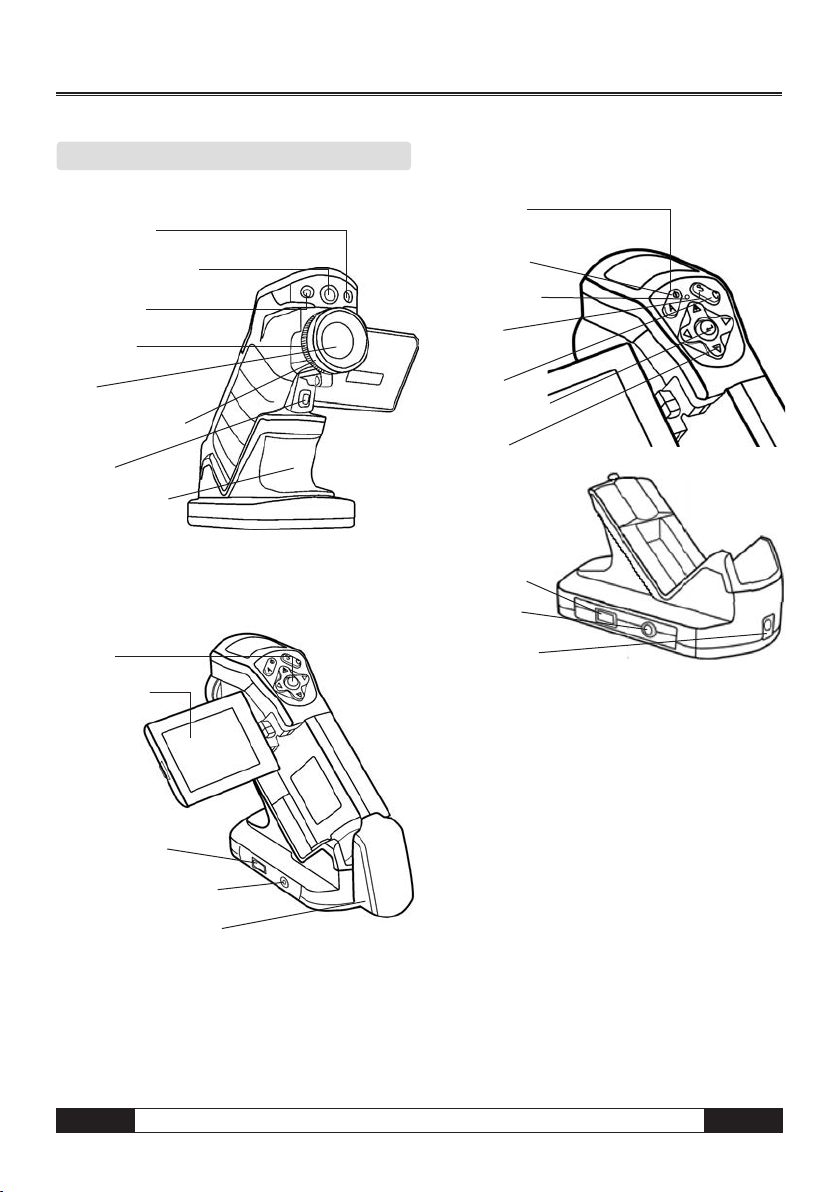
02. COMPONENT GUIDE
Front View
Laser Pointer
Visual CCD Camera
Lamp
Focus Ring
Lens
Lens Locking Ring
Trigger
Multi-functional
Docking Station
Rear View
KeyPad
LCD Monitor
Controls / Multi-function Docking Station
Auto Adjust
Key
Power Key
Power Indicator
Freeze /
Live Key
Cancel Key
Menu / Enter Key
Cursor Key
USB Terminal
Video Output
Terminal
Power Terminal
USB Terminal
Video Output Terminal
Battery / SD Card Cover
EN
Infrared Camera – Operating Manual
B - 4
Page 6
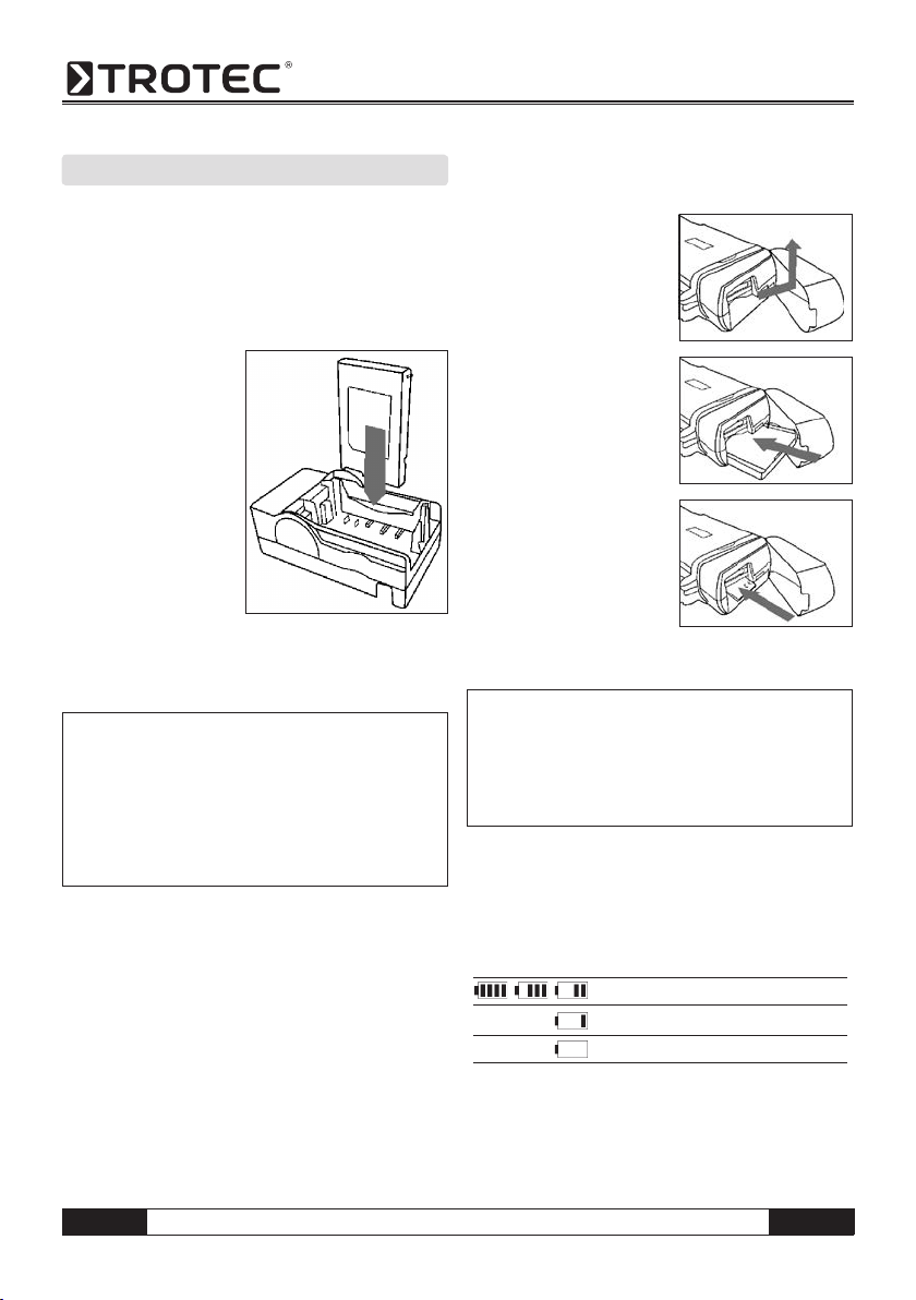
03. PREPARING THE IR CAMERA
Charging the Battery
Proceed as follows when charging the battery for the
first time. This procedure also applies for all subsequent charging cycles, which have to be carried out
when the symbol showing that the battery power is
too low lights up in the display.
1. Position the edge of
the charger so that
it is on the same le vel as the line on the
battery and insert the
battery in the direc tion of the arrow.
2. Attach the power
cord to the battery
charger and plug the
other end into a po wer outlet.
• The charge indicator lights up red while the battery
is charging and lights up green when charging is
complete.
ATTENTION: It is extremely important
that you ensure that the first charging
m
cycle lasts longer than 5 hours but not
longer than 7 hours. Only this will ensure
that the Li-ion cells are fully activated!
Please also ensure that you only use a
suitable charger to charge your battery.
• When the charging cycle has been completed, discon nect the charger from the mains supply and remove
the battery.
• Your camera is equipped with a lithium ion battery
which does not have to be fully discharged before it
can be recharged. The battery does, however, have a
limited life and can be recharged approximately 300x.
We therefore recommend that, as a rule, you only re
charge the battery when it is exhausted or nearly
exhausted.
Charging times will vary according to the surrounding
humidity and battery charge status.
Inserting the Battery / SD Card
Insert the battery into the camera as follows:
1. Check that the power is off
and open the battery cover
in the direction of the arrow.
2. Insert the battery in the
direction of the arrow.
3. Insert the SD card in the
direction of the arrow.
Remove the battery pack when the camera
is not in use.
m
The SD Card must be formatted in
FAT32. Otherwise the IR camera may not
recognize the memory.
Camera
Battery Status Symbols
The following icons indicate the battery status on the
LCD display.
Battery is sufficiently charged
Low battery
Replace or recharge battery
B - 5
Infrared Camera – Operating Manual
EN
Page 7
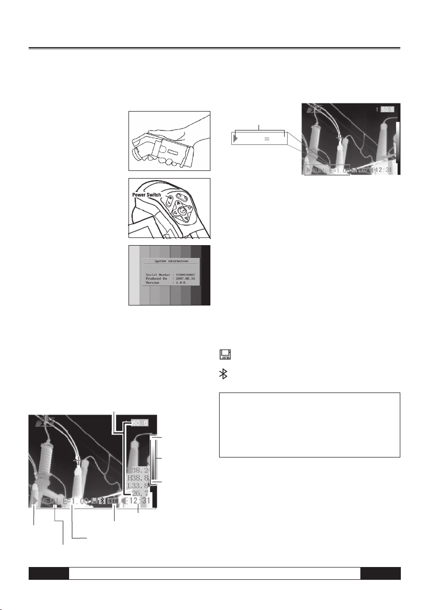
Powering On or Off
NULL E
1.00
The power indicator shows that the camera is on and
has suffi cient battery power.
1. Hold the camera as
shown, place your thumb
above the keypad and rest
your forefi nger gently on
the trigger.
2. Press and hold the power
switch for 3 seconds. The
power indicator lights up
green.
3. Shortly afterwards, a start up image appears on the
screen.
4. To power off press the power key and hold for 3 se conds. The power indicator goes off.
Information on the LCD Monitor
The LCD monitor has a fi eld of vision of 100%.
The following view provides you with information on
individual data:
Reading
Upper limit of
colour scale
Colour scale
Information regarding the operating indicator
The operating indicator shows which operating status
the camera is in.
Status of the camera
ZERO
Menu . . . . . . . . . . . . . . . . . . . . .shows the menu mode
Zero . . . . . . . . . . . . . . . . . . . . . . . shows the non-menu
No analysis tools is selected
1 - 4 . . . . . . . . . . . . . . . shows the current analysis tool
is sport 1 or spot 2 or spot 3
Cap . . . . . . . . . . . . . . . . shows that the tool has been
selected to automatically track
the measuring point (auto tracking)
Isot . . . . . . . . . . . . . . . . . . . . shows the current analysis
tool is isotherm analysis
E. . . . . . . . . . . . . . . . . . . . . . . . . . . . . current emissivity
. . . . . . . . . . . . . . . . . . . . . . . . . . . . SD card inserted
. . . . . . . . . . . . . . . Bluetooth headset has been installed
You will need to enter the zero mode
before you start measuring with your
m
camera. In order to do so press the Cancel key repeatedly until the required zero
mode appears in the display.
Live/
Freeze
EN
Current Emissivity
Operating indicator
Time
Battery Status
Lower limit of
colour scale
Infrared Camera – Operating Manual
B - 6
Page 8
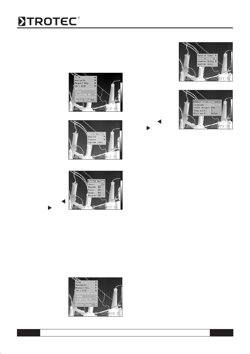
Setting the Time and Date
You need to set the time and date when the IR camera is
powered up for the first time.
1. Check that the IR camera is in zero mode.
2. First press the MENU/
ENTER key and press
the arrow s up / down
t on the menu selec-
tor to get to the menu
item [Setup]. Press the
Menu/Enter key.
3. Press the up s or
down t arrow on the
omni selector to select
[Date & Time] then
press the MENU/
ENTER key.
4. Setting the time and date.
• Press the up s or
down t arrow on
the omni selector to
select a field.
• Press the arrow
left / right in the
menu selector to set the values.
5. Press the MENU/ENTER key to save the changes or
press the C key to close the window without saving
any new settings.
Individual settings
This menu item can be used to change the style of
the menu system.
1. Check that the IR camera is in zero mode.
2. Press the MENU/EN TER key then press
the up s or down
t arrow on the
omni selector to se lect the [Setup] menu.
3. Press the up s or
down t arrow on the
omni selector to select
[Local], then press the
MENU/ENTER key.
4. Local settings.
• Press the up s or
down t arrow on
the omni selector to
select a field.
• Press the
left or
right arrow on the
omni selector to set
the values.
5. Press the MENU/ENTER key to save the changes or
press the C key to close the window without saving
any new settings.
Local Settings
Language . . . . selects the language used in the menus
and messages
Units of temperature . . . . . . sets the units of tempera-
ture for the temperature scale ( °C / °F)
Temp unit . . . . . . . . . . .sets the format of the displayed
temperature unit of the camera (°C or °F)
Units of distance . . . . . . . . . . sets the units of distance
(metres/feet)
Video-out . . . . . .. . . . . . . . . sets the format (PAL / NTSC)
B - 7
Infrared Camera – Operating Manual
EN
Page 9
04. BASIC FUNCTIONS
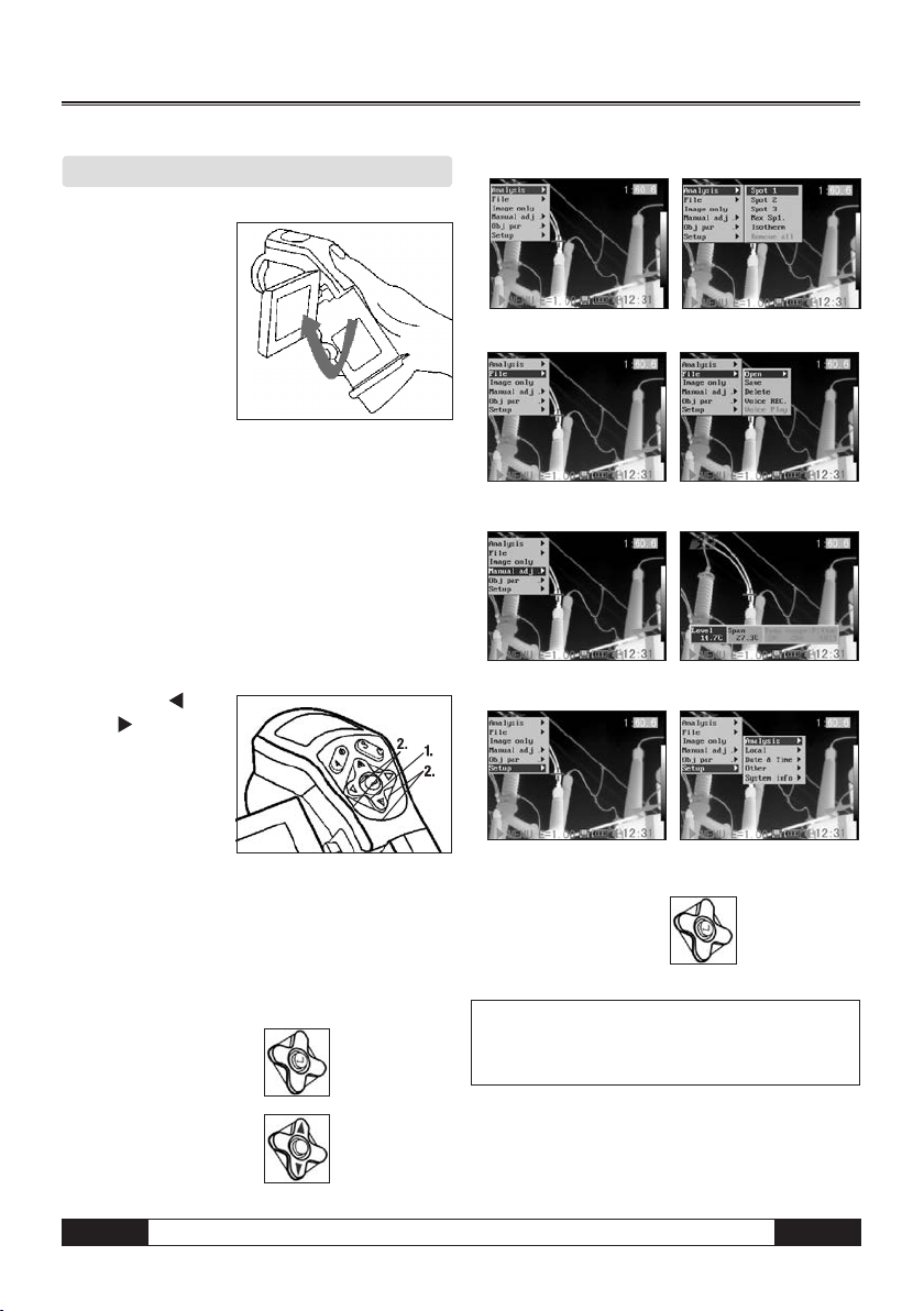
Using the LCD Monitor
The LCD monitor can
be used for measuring
or to view thermal images and adjust menu
settings.
1. Open the LCD display
in the direction of
the arrow.
2 . Point the IR camera at the measuring object.
• For the best possible temperature readings please
ensure that the measuring target is in the centre of
the display.
• The LCD monitor will switch itself off when closed.
Selecting Menus and Settings
You can select the settings by pressing the MENU/
ENTER key.
1.
Press the MENU/ENTER key.
2. Press the
right or up / down
arrow (2) on the
omni selector.
3. Press the MENU/
ENTER key (1).
left,
(1).
Analysis Menu
File Menu
File Menu
Setup Menu
Example
1. Press the MENU/
ENTER key.
2. Use the omni selector
to select a function.
EN
4. Use the omni selector
to select a setting.
The menu items displayed can vary
depending on the individual settings!
m
Infrared Camera – Operating Manual
B - 8
Page 10

Performing a Reset
You can reset the menu and button operation settings
to default.
1. Turn off the IR camera.
2. Press the C key and keep
pressed. Now press the
On/Off key and keep
pressed for several se conds until the camera
has powered on. Release
the C key as soon as the message “init parameters”
appears in the display.
The data that is already stored in the
memory will not be deleted when you
m
reset the menu and button operation
settings to default.
05. MEASURING
Manual Focusing
1. Check to ensure that the IR camera is in null mode.
2. Point the camera at
the object you wish to
measure.
3. Turn the focus ring
until the measuring
target is fully focused.
4. Do not stop turning
the ring until you have a
sharp image.
B - 9
Thermal and Visual Images
The IR camera can take visual images with the builtin digital camera. Visual images can be used as a
reference for thermal images.
1. Press the MENU/ENTER key.
2. Press the up s or
down t arrow on the
omni selector to select
menu item [IR/CCD].
Infrared Camera – Operating Manual
EN
Page 11

3. Press the left /
right key on the
omni selector to get
to the menu item [IR /
CCD-Setup] and press
left / right to ad-
just the display mode.
• IR . . . . . . . . . . . . . . . . . only the IR image is displayed
• Vision . . . . . . . . . . . only the visual image is displayed
• DuoVision . . . . . . . . both the IR and the visual image
are displayed
Moving the DuoVision area
Move upwards (C + UP s) Move downwards (C + DOWN t)
DuoVision
In Duovision display mode, see the thermal images
fuse into the visible images.
IR
In this mode, you can use
the analysis tools to
analyse the target. The
image is partly displayed
in pseudeocolours.
Vision
In this mode, you can
see the image in full
colour. But you can not
use any analysis tools to
analyse the target.
DuoVision
In this mode the IR and
the CCD image are displayed as overlapping
images. You can use the
analysis tools to analyse
the target object.
If the IR image is slightly
displaced, press the C key and the arrow keys in order
to adjust the thermal image so that it covers the visual
image.
Move left (C + LEFT ) Move right (C + RIGHT )
WARNING! Do NOT change the name of
m
the directory into any name other than
the one mentioned above. The camera
may otherwise fail to recognise the
memory card!
Image Adjustment
You can adjust the Level (brightness) and Span (contrast) of the image captured by the IR camera manually
or automatically.
Automatic Setting
The IR camera will automatically adjust the brightness
and/or contrast when you press the A key.
Manual Setting
You can change the level (brightness) and the range
(contrast) of the image manually by scrolling through
the menu system or by pressing one of the arrows on
the omni selector. Press the s up / down t arrow
to change the range and the
change the level (only works in ZERO mode).
1. Press the MENU/ENTER key.
2. Press the s up /
down t arrow on the
omni selector until you
reach the menu item
[Manual Adj.].
right / left arrow to
EN
Infrared Camera – Operating Manual
B - 10
Page 12

3. Setting the Level and
Range.
• Press the left or right
arrow on the omni
selector to select a
field.
• Press the up or down arrow on the omni selector
to set the values.
4. Press the MENU/ENTER key to save the changes or
press the C key to close the window without saving
any new settings.
Image Settings
1. Press the MENU/ENTER key.
2. Press the s up or
down t arrow on the
omni selector to se lect the menu item
Iron, then Press the
MENU/ENTER key.
Press the
left / right
key to select the desired colour.
Further Settings
1. Press the MENU/ENTER
key and change to the
menu item [System
Setup]. Confirm your
entry.
2. Press the s up or
down t arrow on
the omni selector un til you reach the menu
item [Camera Setup]
and press the MENU/
ENTER key.
3. Selecting image settings.
• Press the s up or down t arrow on the omni
selector to reach a new box.
• Press the
left or right arrow on the omni
selector to select a new setting.
4. Press the MENU/ENTER key to save the changes or
press the C key to close the window without saving
any new settings.
Information regarding image settings
Auto adjust
Sets the function of the A key. There are three options:
Level and range, Level, Range.
- Level and range
The camera will automatically adjust the level (bright ness) and span (contrast) of the image to the optimum
setting.
- Level
The camera will automatically adjust the level
(brightness) of the image.
- Range
The camera will automatically adjust the span (contrast)
of the image.
Continuous adj
Determines whether the brightness and contrast are
adjusted automatically on the monitor while the user
is operating the camera.
- Level and span
The brightness and contrast are adjusted automatically.
- Level
The camera will automatically adjust the level
(brightness) of the image.
- None
The brightness and contrast will not be adjusted auto matically.
Measurement Range
The brightness can be reduced by using the integrated filter or an additional filter lens (optional only for
high temperature cameras).
1. Press the MENU/ENTER key.
2. Press up s and down
t arrow on the omni
selector to select [Ma nual adj.], then press
the MENU/ENTER key.
B - 11
Infrared Camera – Operating Manual
EN
Page 13

3. Setting the measurement range.
• Press the up s or
down t arrow on
the omni selector to
select range.
• Press the left
right
arrow on the
or
omni selector to set the measurement range.
• This option is unavailable when the image is frozen.
4. Selecting the measuring range when using optional
lenses.
• Having selected the
box for the mea suring range, press
the keys s up /
down t simultane-
ously to set the
temperature range
for the lens in use.
Type Zero A B C D E
Lens 20° 12.8° 38° 3.8° 6.4° 9°
5. Press the MENU/ENTER key to close the window
when this step is completed.
Setting Analysis Parameters
1. Press the MENU/ENTER key.
2. Press up and down
arrow on the omni se lector to select [Ana ysis], then press the
MENU/ENTER key.
3. Setting the analysis
parameters
• Press the arrow up s /
down t on the se-
lector to get to the
menu item [Object
Setup].
• Press either the s up /
down t or
left / right key on the omni
selector to set the values.
4. Press the MENU/ENTER
key to save the chan ges or press the C key
to close the window
without saving any new
settings.
Freezing / Activating an Image
You can freeze or activate a thermal image by pressing the S key on the selector.
1. Check that the IR came-
ra is in zero mode.
2. Press the S key to freeze
the image.
3. Press the S key again to activate the image.
EN
Infrared Camera – Operating Manual
B - 12
Page 14

About the analysis parameters:
Emissivity
Different objects have different emissivity values. Set
different emissivity values to measure different object.
Distance
Objects can be at different distances from the IR camera. Set the respective distance to the measuring
object.
Amb Temp
Enter the ambient temperature or Trefl., ie, the surface
temperature of radiating/reflecting objects which are
close to the surface you wish to measure and which
could have an effect on the following measurement.
Humidity
Enter the ambient humidity.
Obj Comparison
COMPAROBJ1 can be
set to denote either a
measuring spot or an
area. COMPAROBJ2 can
be set to denote either a
reference temperature,
a measuring spot or an
area. The difference between the temperatures measured with 1 and 2 is displayed in the bottom righthand corner of the LCD, e.g. COMPAROB is SPOT1
(35.4°C) and COMPAROBJ 2 is REF TEMP (30°C), then
the difference between the 2 values is 5.4°C.
Ref Temp
Acts as a means of comparison with a spot, area or
profile
Analysis Settings
1. Press the MENU/
ENTER key.
2. Press the up s and
down t arrow on the
omni selector to select
the menu item
[Analysis], then press the MENU/ENTER key.
3. Press the up s and
down t arrow on the
omni selector to select
[Setup], then press
the MENU/ENTER key.
4. Setting analysis para meters.
• Press the up / down
arrow on the omni se lector to select a field
• Press the left or right arrow on the selector to set
the values.
5. Press the MENU/ENTRY key to save the changes or
press the C key to close the window without saving
any new settings.
About the analysis settings:
Alarm
The temperature alarm can be activated or deactivated. When the temperature alarm is activated, the
measuring value of Spot 5 (EC 060 V) / 10 (EC 060
V+) is displayed in red when the setting “Maximum”
has been previously selected and the temperature
of the measuring point is equal to or greater than
the defined alarm temperature. When Spot 5 has
been set to “Minimum” when the measuring point
is measured and the temperature is either identical
to or lower than the defined alarm temperature, then
the temperature value also appears in alarm mode.
Alarm temp
Sets the alarm temperature thresholds.
Correct temp
Corrects the measured temperature reading to ensure measurement accuracy under special conditions.
Zero point offset of the calibration curve.
WARNING: Zero point displacement of
the calibration curve!
m
B - 13
Infrared Camera – Operating Manual
EN
Page 15

Saturation colour
When activated, the width of the image with the highest temperature is coloured green.
Isotherm width
Sets the width of isothermal intervals. The width can be
adjusted from 0.1 to the upper limit of the maximum
temperature measurement range under this condition.
Isotherm colour
Sets the colour of the isotherm interval to either
green, black opr white or to transparent.
Isotherm Type
Shows all temperatures within the set
isotherm intervals in one colour and in
addition all areas which are warmer than
the upper interval threshold in a different
Shows all temperatures within the set iso-
therm intervals in one colour and in addition
all areas which are colder than the lower
interval threshold in a different colour.
Shows the isotherm interval and all areas
which are warmer than the upper interval
Shows the isotherm interval and all areas
which are colder than the upper interval
Shows the set isotherm interval in one
colour. The rest of the image is displayed
colour.
threshold in the same colour.
threshold in the same colour.
in IR pseudo colours.
Isotherm
Type
Dual
Above
Dual
Below
Above
Below
Interval
Isotherm alarm
The alarm threshold value can be set between 1 and 100
and describes the proportion (in %) between 1/100 and
100/100 of the area of the LCD, eg. the isotherm range
is between 35°C and 40°C and the Iso-Alarm is 100. In
this case the alarm is triggered when 100% of the area
shown in the LCD is between 35°C and 40°C and the
whole area of the LCD is correspondingly “isotherm”- coloured. If the alarm threshold value is set, for example, at
40, the alarm will be triggered when 40% of the area of
the LCD is “isotherm”- coloured.
Spot Analysis
The following subject matter briefly explains how to
set the analysis tools on the thermal image.
1. Press the MENU/ENTER key.
2. Press the up s or
down t key on the
omni selector to get to
the menu item [Analy sis].
3. Setting the spot analysis
• Press the up s or
down t arrow on
the omni selector
to select a spot,
then press MENU/
ENTER key. One or
more crosshairs will
appear on the screen.
• Spot 5 will automatically track the highest or
lowest spot on the screen.
4. Moving the analysis spot
• Start from Step 1 to
set or select a spot
analysis.
• Press the up s,
down t, left
right
arrow on the
,
omni selector to
move the activated
spot.
Temperature value
of the current spot
will be modified
5. Removing the meas uring spots.
Measured
Temperature
• Start with Step 1
and select the meas uring spot you wish to remove.
• Press C to remove the measuring spot.
Tracking the measuring spot
Set Spot 5 or Spot 10 so that it tracks the highest/
lowest point on the display.
EN
Infrared Camera – Operating Manual
B - 14
Page 16

- Maximum
Set Spot 5 so that it always follows the hottest
spot in the display.
- Minimum
Set Spot 5 or 10 so that it always follows the
coldest spot in the display.
Area Analysis AREA (optional EC 060 V+)
1. Press the MENU/
ENTER key.
2. Press the up s and
down t key on the
omni seletor to get to
the menu item [Ana lysis].
3. Press the arrow ups
and down t to get
to the menu item [Area].
4. Setting the area
analysis.
•
Press the arrow
up s / down t
on the omni
selector to select
the area. Confirm
with Menu/Enter.
A further menu item appears on the LCD.
• A display panel appears in the top right-hand cor ner. It shows the Max/Min and Average temperature
of the selected area.
• Press the
left or right key to select
between the Max, Min or Average temperature
of the selected area.
• When Area 5 is selected, the Max, Min and Ave rage temperature are displayed s
imultaneous
ly.
5. Moving the area
•
Start with item 1 of the
menu to determine the
area you wish to select.
The area can be mo ved by pressing s up,
down t, left or
right .
6. Deleting the area
Start with item 1 of the menu or select the
•
menu item [Area].
• Press the C key to delete the selected area.
• Change the form / size of the analysis area.
UP + Left
DOWN + Left
UP + Right
DOWN + Right
Professional Analysis PROFILE (optional EC 060 V+)
1. Press the MENU/
ENTER key.
2. Press the s up/
down t arrow on
the omni selector to
reach the menu item
[Analysis].
3. Press the s up/
down t arrow to
reach the menu item
[Profile]. A profile line
appears on the LCD.
B - 15
Infrared Camera – Operating Manual
EN
Page 17

Moving the Analysis
1. Start with Step 1 of the menu item to reach the
desired area.
2. Press the s up /
down t arrow on
the omni selector to
move the selected
profile
Deleting the Profile Analysis
1. Start with Step 1 of the menu item to select the
desired area.
2. Press C to delete the Profile Analysis.
Isotherm Analysis
1. Press the MENU/EN TER key.
s
2. Press the
up/
down t arrow on
the omni selector to
reach the menu item
[Analysis].
s
3. Press the arrow
up / down t to get
to the menu item
[Isotherm] and press
the MENU/ENTER key.
Areas that are not
within the selected isotherm range are displayed in
a different colour.
4. Setting the isotherm
range.
• Start with Step 1 to
select the Isotherm
Analysis.
• Press the arrow
s
key
up / down
t
on the omni
selector to move the
isotherm range upwards or downwards. Press the
left / right key to increase or decrease the isotherm
range by changing the lower isotherm level (IL).
• The letters IL and IH appear in the bottom
right-hand corner. IH is the upper threshold
and IL the lower threshold of the isotherm
range.
Removing Analysis Tools
The following subject matter briefly explains how to
remove the analysis tools that have been placed on
the screen.
1. Press MENU/ENTER.
2. Press the up s and
down t arrow on the
omni selector to se lect the menu item
[Analysis].
3. Select the analysis
tool you wish to remove.
4. Press the C key to delete the tool or press the MENU/
ENTER key to delete all the analysis tools.
Saving Images
Press the S key to save a previously frozen image into
the memory. You can also save an image into the memory without freezing it first by keeping the key on the
omni selector pressed for 3 seconds while the camera
is in zero mode.
1. Press the MENU/ENTER key.
2. Press the
left or
right arrow on the
omni selector to se lect the menu item
[File].
3. Press s up and
down t arrow on the
omni selector to se lect [Save], then press
the MENU/ENTER key
to save the image.The
display mode shows
the memory mode.
EN
Infrared Camera – Operating Manual
B - 16
Page 18

4. The name of the sa ved image will be dis played on the screen.
Trigger Information
Save: Press the trigger to save an image.
Laser on: Press the trigger to activate the laser.
Lamp on: Press the trigger to turn on the integrated lamp.
Voice Annotations (optional)
1. Install the Bluetooth headset (optional).
2. To freeze an image
press the MENU/
ENTER key.
3. Press the s up/
down t arrow on
the omni selector to
select the [File] menu.
4. Press s up/down
t arrow on the
omni selector to select
[VoiceREC.], then press
the MENU/ENTER key.
The message [Voice
Recording] will appear
on the LCD monitor.
5. Speak into the headset microphone. To stop recor ding press the C key.
6. Save the image.
Trigger Settings
The trigger can be set to perform a variety of different
functions: it can be used to store images or to switch
the laser or the lamp on or off.
1. Press the MENU/EN TER key and then the
arrow s up / down
t on the omni selector
to get to the menu item
[Lighter on] and press
the MENU/ENTER key.
2. Press the up and down arrow on the omni selec tor to select menu item [Others] and then press
the MENU/ENTER key.
06. RECORDING AND DELETING
Opening Images
You can view and analyse the recorded images on the
LCD monitor.
1. Press the MENU/ENTER key.
2. Press the s up and
down t arrow on the
omni selector to select
the [File] menu.
3. Press s up and down
t arrow on the
omni selector to select
[File], then press the
MENU/ENTER key.
4. Select an image, then
press MENU/ENTER key
to open the image.
You can choose to ana lyse an image or add
your own voice anno tations after the image
has been opened.
Selecting Images
1. When you have selected [Open] or [Delete] in the [File]
menu, a message will appear in the lowerleft-hand
corner of the screen as shown below.
<DIR> GZSAT001
Open SAT00001.SA
2. If the image you wish to open or delete is not in the
current folder, press the [UP] arrow on the omni selector
until the following message appears.
B - 17
Infrared Camera – Operating Manual
EN
Page 19

.. <DIR>
Enter or Delete
3. Press the C key and then the S key to activate the
image.
Selecting the Name of the Current Folder
1. Press the MENU/ENTER key.
2. Press the s up and
down t arrow on the
omni selector to select
the menu item [Setup],
then press the MENU/
ENTER key.
3. Press the arrow key
s up / down t on
the omni selector to
get to the menu item
[File]. and press the
MENU/ENTER key.
4. Select an image and
press the MENU/
ENTER key to open
the image (see Selec ting an Image). You can
either analyse an
image or add a voice
annotation once the image has been opened.
Voice Annotations
1. Install the Bluetooth
headset (optional) and
open an image.
2. Press the MENU/ENTER
key, then press the up
or down arrow on the
omni selector to select the [File] menu and confirm.
3. Press the s up
or down t arrow on
the omni selector to
select [Voice Play],
then press the MENU/
ENTER key. The
[Playing Record]
message will appear on the LCD monitor.
4. Press the C key to delete the voice annotation.
Deleting Images
Please note that deleted images cannot be
m
recovered. Exercise caution before deleting any images !
1. Press MENU/ENTER
key then press s up
or down t arrow on
the omni selector to se lect the [File] menu.
2. Press s up or downt
arrow on the omni
selector to select
[Delete], then press
the MENU/ENTER key.
3. Select an image, then
press the MENU/ENTER
key to delete the se lected image.
EN
4.
Press the C key to exit
Infrared Camera – Operating Manual
.
B - 18
Page 20

07. READING OUT IMAGES
Reading Out Images from the SD Card
You can remove the SD card from your camera and
download the images to your computer via the supplied
SD card reader.
1 . Open the battery / SD
card cover and press
the SD card lightly, then
the SD card will pop-up
automatic.
2 . You can download the IR images directly from SD
card or via SD card reader.
08. CONNECTING AND READING OUT
Charging the Battery via the Docking Station
The rechargeable battery can also be recharged via the
docking station using an optionally available adapter.
3 . The power LED of the camera blinks while the battery
is charging and lights up green when charging is
complete. Unplug the power adapter. The best
way to recharge the battery is to use the char ging station included in the scope of delivery.The IR
camera can also be powered by the mains using the
docking station.This is an extremely useful feature
when the camera is used in continuous operation. Ple ase ensure that you only use original Trotec mains
adapters to avoid any damage from occurring to
your camera.
Connecting to a monitor
The camera can be connected to a video-compatible
monitor to view and analyse images via the video cable
included in the scope of delivery .
1. Turn off the IR camera.
2. Connect the video cable
to the video out terminal
of the multi-function
docking station.
3. Plug the other end of
the video cable into the
monitor‘s in jack
4. Turn on the monitor
and the IR camera.
1. Attach power adaptor to the power terminal on the
multi-functional dock.
2. Connect the adapter cable to the charger and plug into
the mains socket.
B - 19
Infrared Camera – Operating Manual
Connecting to a Computer
(only possible with cameras with USB interface or
real-time capability)
Connect the dongle included in the scope of delivery to
a free USB port. The software will not open without the
dongle. Go to “show” => “IR camera model” in the menu
to select the camera type which you would like to connect
to your computer. Connect the USB cable included in the
scope of delivery to the USB port of your computer and the
connection point of your multi-function docking station.
There is no need to switch off either your PC or your camera while you are setting up this connection. See your
computer handbook or instructions to find out where
the USB port is. The USB port is only used for optionally
available software.
EN
Page 21

Connect the USB cable supplied included in the scope
of delivery to the USB port of your PC and the multifunction docking port.
There is no need to turn off the computer or camera
when setting up this connection.
Please refer to your computer manual for information regarding the location of the USB port.
Installing the Driver
Connect the USB included in the scope of delivery to the
USB port of your PC and the USB port of your camera. Set
the SAT real-time disk (optional) to the CD-ROM driver.
Users of Windows XP Professional /
Windows 2000 must first log in as
m
as administrator (computer system
administrator) to install programs.
1. After a few moments,
the following dia logue will appear.
2. Select [No, not this time]
then click [Next >].
3. Select [Install from a list
or location (Advanced)]
then click [Next >].
4. Select [Include this lo cation in the search:]
then click [browse].
Locate the directory of
the driver, and click
[OK] to return to the
previous window.
Then click [Next >].
5. Click [Continue Anyway].
6. Click [Finish] to finish
the driver installation.
Transferring Videos via USB
You can use the real-time software to transfer your thermal videos directly to your computer via USB.
1. Power on the computer.
2. Connect the camera and your computer via the USB
cable.
3. The operating system will recognise your camera
as a removable medium if the drivers have been
installed correctly.
4. You can use the soft
ware to view and
anylyse thermal videos
in real-time and to
save them on to your
hard drive.
EN
Infrared Camera – Operating Manual
B - 20
Page 22

Troubleshooting
If you wish to use the optional real-time software and encounter any problems while connecting your IR camera
to a computer, please read the following tips and advice.
First, check the following:
1. Does your computer comply with these requirements?
Ensure the system has a built-in USB2 port and that it
comes with Windows XP preinstalled.
The USB interface idoes not support systems which
do not comply with the above conditions.
2. Is the camera connected correctly to your computer?
See „Connecting your camera to a computer“.
3. Is the battery sufficiently charged?
We advise that you connect your camera to the mains
supply when it is connected to your computer
(mains adapter optional).
4. If the USB driver is not correctly installed, Windows
may not recognise the USB driver. Please contact the
manufacturer of your motherboard to get the latest
driver updates.
5. The USB2.0 real-time transmission function may not
work properly with some motherboard chipsets. In
this case, connect the IR camera to another computer
which has a chipset which is in the chipset sup porting list and try again.
Using the Bluetooth headset
Your infrared camera has Bluetooth. The optionally available Bluetooth headset can be
used to record voice annotations. Follow the
steps below to install your Bluetooth headset.
1. Turn off the camera and the Bluetooth
headset.
2 . Turn on the Bluetooth headset first.
Press and hold the power button (A) for about
5 seconds. The power indicator starts to blink in red
and then blue. The headset is in pairing mode after 2
seconds. The bLED blinks more slowly and turns to blue.
3 . Turn on the camera while the Bluetooth headset
is still blinking. The camera‘s power indicator lights up
green and blinks in blue at the same time. The camera
is preparing to connect with the headset.
4. When the headset is in pair mode press the power
button of the Bluetooth headset for about 2 se conds to set up a connection between the headset
and the camera. The camera‘s LED starts to blink
in shorter one-second intervals. Press the ON/OFF
key of your Bluetooth headset. The Bluetooth sym bol appears in the camera display. The camera LED
now lights up permanently in green and blue! The Blue tooth mode is now activated.
5. When you use the
Bluetooth headset a se cond time, first turn
on the headset. The
blue power indicator
starts to blink. Then
turn on your camera.
When the camera has powered up, repeat the proce dure as described in Step 4 to activate the Blue tooth mode again.
6. You can use the headset to record voice annota tions and to listen to ones you have already made.
The Bluetooth headset has been successfully
recognised
1. Switching off the Bluetooth headset:
Press and hold the ON/OFF key until the red LED
lights up.
2. Switching on the Bluetooth headset:
Press and hold the ON/OFF key until the blue LED
lights up. To charge simply connect the headset to
your PC via the USB cable included in the scope
of delivery.
Optional accessories
- Various lenses
- Additional power supply
- Transport case
B - 21
Infrared Camera – Operating Manual
EN
Page 23

09. CARE AND MAINTENANCE
Use the following procedures to clean the camera
housing, lens, LCD monitor and other parts.
Camera housing
Wipe the housing with a clean, soft, lint-free cloth or
eyeglass wipe.
Lens
Use a blow brush to remove any dust from the lens and
LCD monitor
Use a lens blower brush to remove dust and dirt. If necessary, gently wipe the LCD monitor with soft cloth or
an eyeglass wipe to remove stubborn dirt.
Never rub or apply pressure to on the LCD monitor. This
may cause damage or result in other problems.
Never use thinners, benzene, synthetic cleaners or water
to clean the camera. These substances may cause de-
formations or damage the equipment.
use a clean, dry cloth to remove any dirt or particles that
may still be on the lens. Do NOT use caustic cleaning
agents to clean the camera housing or the lens.
10. TROUBLESHOOTING
Problem Cause Solution
Power is not turned on.
Turn on the camera.
See Turning the Power On / Off.
Insufficient battery voltage. Fully charge the battery.
Camera does not operate.
Poor contact between camera and
battery terminals.
The camera firmware has frozen
up.
Wipe the terminals with a clean,
dry cloth.
Perform a RESET.
Save the images onto your
Internal memory is full.
Camera will not record.
Internal memory not formatted
correctly.
computer and delete them from
the SD card.
Format the memory
in FAT 32 format.
Battery capacity reduced
Battery power exhausted.
because battery was not used for
a year or longer after being fully
Replace the battery with a new
one.
charged.
Battery life is at the end of its life. Replace the battery.
Clean the battery terminals with
a clean cloth. Connect the power
cord to the battery charger and
insert the plug firmly into the
Battery will not charge.
Poor contact between battery and
battery charger.
power outlet.
Battery is at the end of its life. Replace the battery.
EN
Infrared Camera – Operating Manual
B - 22
Page 24

11. EMISSIVITY TABLE
Material Temperature
(°C)
Emissivity
(approx.)
Iron
Polished cast iron 200 0.21
Processed cast iron 20 0.44
Polished tempered
iron
40 ~ 250 0.28
Polished steel ingot 770 ~ 1040 0.52 ~ 0.56
Raw welded steel 945 ~ 1100 0.52 ~ 0.61
Surface ferric oxide 20 0.69
Completely rusty
surface
22 0.66
Rolled iron plate 100 0.74
Oxidized steel 198 ~ 600 0,64 ~ 0,78
Cast iron
(oxidised at 600°C)
Steel
(oxidised at 600°C )
Electrolytic ferric
oxide
198 ~ 600 0.79
125 ~ 520 0.78 ~ 0.82
500 ~ 1200 0.85 ~ 0.89
Iron plate 925 ~ 1120 0.87 ~ 0.95
Cast iron,
heavy ferric oxide
Tempered iron,
ferric oxide
25 0.80
40 ~ 250 0.95
Melting surface 22 0.94
Melting cast iron 1300 ~ 1400 0.29
Melting mild steel 1600 ~ 1800 0.28
Liquid steel 1500 ~ 1650 0,42 ~ 0,53
Pure lead 1515 ~ 1680 0.42 ~ 0.45
Silver
Polished Silver 100 0.05
Material Temperature
(°C)
Emissivity
(approx.)
Nickel
Nickel-chrome
(heat-resistant)
50 ~ 1000 0.65 ~ 0.79
Nickel-chrome alloy 50 ~ 1040 0.64 ~ 0.76
Nickel-chrome alloy
(heat-resistant)
50 ~ 500 0.95 ~ 0.98
Nickel-silver alloy 100 0.14
Lead
Pure lead
(non-oxidised)
125 ~ 225 0.06 ~ 0.08
Stainless steel
18 - 8 25 0.16
304 (8Cr, 18Ni) 215 ~ 490 0.44 ~ 0.36
310 (25Cr, 20Ni) 215 ~ 520 0.90 ~ 0.97
Tin
Commercial tin plate 100 0.07
Strong oxidization 0 ~ 200 0.60
Zinc
Oxidizing at 400°C 400 0.01
Galvanised shining
iron plate
28 0.23
Ash zinc oxide 25 0.28
Magnesium
Magnesia 275 ~ 825 0.55 ~ 0.20
Hg 0 ~ 100 0.09 ~ 0.12
Nickel
Electroplate polishing 25 0.05
Electroplate 20 0.01
Nickel wire 185 ~ 1010 0.09 ~ 0.19
Nickel alloy (oxide) 198 ~ 600 0.37 ~ 0.48
B - 23
Infrared Camera – Operating Manual
EN
Page 25

11. EMISSIVITY TABLE
Material Temperature
Non-metallic materials
Brick 1100 0.75
Firebrick 1100 0.75
Graphite (lamp lack) 96 ~ 225 0.95
Porcelain enamel
(white)
Asphalt 0 ~ 200 0.85
Glass (surface) 23 0.94
Calcimine 20 0.90
Oak 20 0.90
Carbon piece 0.85
Isolation piece 0.91 ~ 0,94
Sheet metal 0.88 ~ 0,90
Glass pipe 0.90
Loop type 0.87
Porcelain enamel
products
Porcelain enamel
designs
Solid materials 0.80 ~ 0.93
Ceramics (vase type) 0.90
Film 0.90 ~ 0.93
Heat resistant glass 200 ~ 540 0.85 ~ 0.95
Aluminium
Polished aluminum 100 0.09
Commercial
aluminum foil
Electrolytic
chromeplate alumina
Mild alumina 25 ~ 600 0.10 ~ 0.20
Strong alumina 25 ~ 600 0.30 ~ 0.40
Copper
Cuprous oxide 800 ~ 1100 0,16 ~ 0,13
(°C)
18 0.90
100 0.09
25 ~ 600 0.55
Emissivity
(approx.)
0.90
0.83 ~ 0.95
Material Temperature
(°C)
Non-metallic materials
Mica 0.94 ~ 0.95
Flame mica 0.90 ~ 0.93
Glass 0.91 ~ 0.92
Semiconductor 0.80 ~ 0.90
Transistor
(plastics sealed)
Transistor
(metal) diode
Pulse transmission 0.91 ~ 0.92
Level chalk layer 0.88 ~ 0.93
Top loop 0.91 ~ 0.92
Electric materials
Epoxy glass plate 0.86
Epoxy hydroxybenzene
plate
Gilded sheet copper 0.30
Solder-coated copper 0.35
Tin-coated lead wire 0.28
Brass wire 0.87 ~ 0.88
Block talcum terminal 0.87
Emissivity
(approx.)
0.30 ~ 0.40
0.89 ~ 0.90
0.80
Copper
Copper mirror 100 0.05
Strong copper oxide 25 0.078
Liquid copper 1080 ~ 1280 0.16 ~ 0.13
Brass
Brass mirror 28 0.03
Brass oxide 200 ~ 600 0.61 ~ 0.59
Chrome
Polished chrome 40 ~ 1090 0.08 ~ 0.36
Gold
Gold mirror 230 ~ 630 0.02
EN
Infrared Camera – Operating Manual
B - 24
Page 26

12. TECHNICAL DATA
Description Characteristics Performance
Type Microbolometer UFPA
Detector
Spectral range 8~14 microns
Resolution 160 x 120
NETD 0.08°C
Imaging Performance
Lens / focusing 20° x 15°, manual focusing
Min focal distance 0.1 m
Built-in digital video 640 x 480 pixels, full colour
Visual
Image Presentation
Features
Lamp
Video output PAL / NTSC
Image display Pseudocolour, multi-palettes
Image freeze Live or freeze
File function Removable SD card, up to 2 GB.
To produce clear, high-quality
visual images in dark areas
Measurement
Temperature range -20°C~250°C
Accuracy +2 °C or +2%
Spots 2 - 10 spots
Tracks the highest or lowest
Temperature tracking
temperature spot automatically
in the whole image
The user can select alarm tempe-
Analysis Functions
Temperature alarm
rature thresholds which trigger an
audible alarm when exceeded
Adjustment
Correction
Level and span can be adjusted
automatically or manually
Emissivity, distance, environmental
temperature, relative humidity
Software Analysis software Report generation software
Type Type II
Laser pointer
Power consumption 1 mw
Wavelength 635 nm (red)
B - 25
Infrared Camera – Operating Manual
EN
Page 27

12. TECHNICAL DATA
Description Characteristics Performance
Settings Time, date, °C or °F
Power off Automatically
System
Power supply
Lithium battery or 8 ~ 11V DC
supply to charge the battery inside
BWT ~ 2.5 hours
Operational temperature -15 °C ~ 50 °C
Environmental
specification
Storage temperature -40 °C ~ 70 °C
Relative humidity 10 ~ 95%
Mechanism
Interfaces
Electric
with enhanced docking port (enhanced interface)
USB2.0 , Bluetooth (optional),
Video output
Physical Characteristics Weight ≈ 500g (including battery)
EN
Infrared Camera – Operating Manual
B - 26
Page 28

TROTEC® GmbH & Co. KG • Grebbener Straße 7 • D-52525 Heinsberg
Tel.: +49 2452 962 - 400 • Fax: +49 2452 962 - 200
www.trotec.de • E-mail: info@trotec.de
 Loading...