

Page 1
OPERATING MANUAL
PULSE CURRENT
MEASURING SYSTEM
EN
TRT-BA-PD200-HS-006-EN
PD200
Page 2

Operating manual – pulse current measuring system PD200
A - 1
EN
Table of contents
01. Safety .........................A - 01
02. Intended use ......................A - 02
03. Scope of delivery ..................A - 02
3.1 Standard scope of delivery ......... A - 02
3.2 Optional accessories .............. A - 03
3.3 Supplies .......................A - 03
04. Operating elements, displays and
connections ......................A - 04
4.1 Pulse generator PD200 G ..........A - 04
4.2 Pulse receiver PD200 E ............A - 05
05. Functional check ..................A - 05
5.1 Battery testing pulse receiver ....... A - 05
5.2 Voltage testing pulse generator ......A - 05
5.3 Checking the functional interaction
of both devices ..................A - 06
06. Leak detection ....................A - 06
6.1 General functioning ...............A - 06
6.2 Preparing the measurement ........A - 07
6.3 Preparation warm/green roof ....... A - 07
6.3.1 Installation of loop wiring .....A - 07
6.3.2 Using the gravel claw
(optional accessories) ........A - 08
6.3.3 Connecting the pulse generator A - 08
6.3.4 Connecting the pulse receiver .. A - 08
6.4 Preparation cold roof .............A - 08
6.4.1 Installation of loop wiring .....A - 08
6.4.2 Connecting the pulse generator A - 09
6.4.3 Connecting the pulse receiver .. A - 10
6.5 Detection ......................A - 10
07. Avoiding measurement errors ........A - 10
7.1 Shielding ...................... A - 10
7.2 Supposed leak at the centre
of the measuring surface ..........A - 11
7.3 Prolonged drought ...............A - 11
7.4 Earthed metal parts .............. A - 11
08. Checking of lined ponds and swimming
pools with non-conducting sealing
....
A - 11
09. Troubleshooting
...................
A - 12
10. Maintenance and service
............
A - 12
10.1 Battery change ................. A - 12
10.2 Maintenance and service of
the device .................... A - 12
11. Technical data
.....................
A - 12
11.1 Pulse generator PD200 G. ........A - 12
11.2 Pulse receiver PD200 E ..........A - 12
11.3 Particular equipment features ...... A - 13
12. Miscellaneous
.....................
A - 13
12.1 Operational reliability ............ A - 13
12.2 Seminars ..................... A - 13
12.3 Disposal ...................... A - 13
This release replaces all previous releases. No part of this publication may be reproduced
without written permission. The same applies for electronically processing, duplicating or
spreading the publication. Subject to technical changes. All rights reserved. Trademarks are
used without guarantee that they may be used freely and primarily following the spelling of
the manufacturer. The product names used are registered and should be treated appropriately.
Changes to construction in the interests of constant improvements to the product, as well as
changes to the shape and colour are reserved. Scope of delivery may vary from product images.
This document was produced with all due care. We accept no liability whatsoever for mistakes
or omissions. © TROTEC
®
The measuring device at hand was built according to
current state-of-the-art technology and fulfils valid
European and national directives. This conformity has
been tested and the corresponding declarations and
documents are kept on file by the manufacturer.
To keep this condition and ensure safe operation,
as a user, you must observe the following safety
instructions:
01. Safety
We accept no liability for damages caused by nonobservance of this manual or unprofessional
handling. Any warranty claims are voided in such
cases!
m Before starting the measuring device for the
first time, read this manual from cover to
cover!
Page 3
Operating manual – pulse current measuring system PD200
EN
A - 2
For reasons of safety and conformity (CE), any
unauthorised change made to the device construction
or components which are to be used with the
measuring device are prohibited!
Before using the device, observe the following:
• Never measure live parts.
• The only party responsible for determining
measured results to be valid, drawing conclusions
and deriving actions is the user! The correctness
of the results presented is excluded from any
liability or guarantee. Liability for damages which
have been caused by utilising the presented
measured results is strictly excluded.
02. Intended use
The PD200 system is a professional measuring device
based on the pulse current method for the pinpoint
location of grounded leaks in non-conducting plastic
foils.
Fields of application i.a.:
• warm roofs, cold roofs and greened flat roofs
• roof-top terraces
• balconies
• lined ponds, swimming pools
• plastic covered landfills, dumps
The power supply has to comply with the device
type and the mains connection must be provided
with a proper protective earth conductor. The device
may only be used for the given intended use while
complying with the specified technical data.
Any other use is considered misuse and contrary to
the intended use.
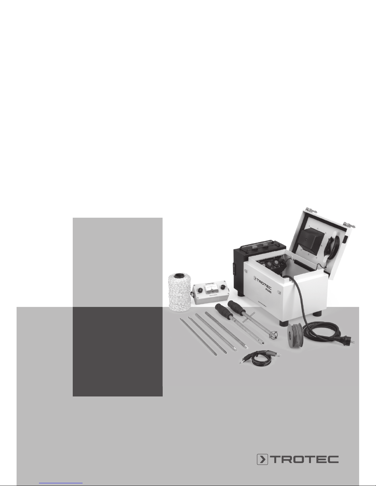
03. Scope of delivery
3.1 Standard scope of delivery
•
1
transport case with carrying handle
and 2 safety locks
1
Page 4
Operating manual – pulse current measuring system PD200
A - 3
EN
0
µA
50
+–
50
40 40
30 30
20 20
10 10
+
–
• 2 integrated pulse generator PD200 G
with power cable
• 1 x connection cable with clip terminal
in the lid, black
3
length 8 m
•
4
1 x reel PD200 loop wiring, length 200 m
•
5
1 x reel PD200 earth cable
extension with banana jack,
red, length 25 m
•
6
compact, battery-powered pulse receiver
PD200 E with carrying strap
•
7 8
2 x take-apart measuring rods with rubber
grip (3-part, length: 1.00 m) incl. 1 x clamping
spring and 1 x integrated uncoiling aid for loop
wiring
• 1 x connecting cable each for the measuring rods,
red
9
and black
10
•
11
6 x batteries of type LR06 / AM-3 | AA | Mignon
3.2 Optional accessories
•
12
gravel claw for a simplified laying of loop wiring
under the gravel fill
(art. no. 3.510.010.003)
3.3 Supplies
•
4
1 x spare reel of PD200 loop wiring,
length 200 m (art. no. 3.510.010.005)
•
5
1 x spare reel of PD200 earth cable extension,
red, length 25 m (art. no. 3.510.010.004)
3
2
4
6
7
8
5
9
11
12
10
Page 5
Operating manual – pulse current measuring system PD200
EN
A - 4
+
–
04. Operating elements, displays and connections
4.1 Pulse generator PD200 G
•
A
red warning light for earthing control
•
B
green lamp for visual control of
current pulses (flashes green)
•
C
rocker switch with indicator light, green
•
D
primary fuse (PTC) F1
•
E
secondary fuse (PTC) F2
•
F
pressure switch, red, for activation of an additional acoustic signal for acoustic control of current
pulses
•
G
pressure switch, green, for switching on the
external earthing
•
H
positive connector, red
•
I
negative connector, black
•
J
transport handle
A
B
DC E F G H
I
J
Page 6

Operating manual – pulse current measuring system PD200
A - 5
EN
+
–
0
µA
50
+–
50
40 40
30 30
20 20
10 10
05. Functional check
5.1 Battery testing pulse receiver PD200 E
Do not switch on the receiver. Set the right rotary
switch to "BAT.-CHECK". If the needle on the
indicating instrument [µA]
L
deflects to the right to at
least 30 µA, the battery capacity is sufficient and the
device ready for use. Then turn the right rotary switch
to position "4".
5.2 Voltage testing pulse generator PD200 G
Plug the power cable into an earthed safety socket.
Flip the rocker switch
C
to position "I" and the green
indicator light indicates the mains connection.
4.2 Pulse receiver PD200 E
•
K
rotary switch "ON/OFF", adjustment for
"0" position
•
L
analogue indicating instrument [µA]
•
M
rotary switch with 6 settings:
attenuation 1-4, 1 = without resistance,
2 = minimum
resistance ... 4 = maximum resistance
test setting (TEST)
battery check (BAT.-CHECK)
•
N
carrying strap
• red
O
and black P connectors for connection
of connection cables with measuring rods
K
M
N
L
L
C
P
O
0
µA
50
+–
50
40 40
30 30
20 20
10 10
Page 7

Operating manual – pulse current measuring system PD200
EN
A - 6
+
–
0
µA
50
+–
50
40 40
30 30
20 20
10 10
5.3 Checking the functional interaction
of both devices
m Before checking, switch off both devices. Set
the rotary switch of pulse receiver PD200 E
M
to "TEST". If the switch is in a different
position, the receiver might be damaged
when switching on pulse generator PD200 G.
Use the red
9
and black 10 connection cables to
connect the pulse receiver to the receptacles of the
pulse generator
H
I. Ensure the correct colour
assignment black/red.
Switch on the generator. Then switch on the receiver
and use the rotary switch
K
to adjust the indicator
to "0".
The needle of the analogue indicating instrument [µA]
L
must deflect to the right in the pulse frequency.
Also check the pulses by means of the green lamp
B
in the transport case. Switch on the acoustic
signal of the pulse generator
F
.
Interchange the two measuring lines at the pulse
receiver – black cable to red connector and red cable
to black connector – and repeat the procedure. The
needle should now deflect to the left.
+G-
pulse generator
loop wiring
potential lines
leak
06. Leak detection
6.1 General functioning
The method is based on the fact that there is water
both on top of and also underneath the sealing sheet.
This water or moisture serves as conductor. Therefore, leak detection always requires a damp and
hence electrically conducting sealing sheet, regardless of whether the surface is wet to various degrees,
gravelled or greened.
The PD200 pulse generator gives of current pulses
with a voltage of 40 V. The current finds its path to the
point of leakage via the moisture. The PD200 receiver
is used to measure the potential difference. The
needle of the indicating instrument deflects to the
direction with the higher potential, indicating the
direction for the locator. This way you are led to the
leak, to the position where moisture enters.
F H
I
K M
L
Page 8

Operating manual – pulse current measuring system PD200
A - 7
EN
6.3 Preparation warm/green roof
6.3.1 Installation of loop wiring
Figure: sectional drawings warm roof
loop wiring
fill
loop wiring
fill
Before measuring, the bare cord 4 (loop wiring)
is to be laid as closed circuit around the roof
area to be examined observing a minimum
distance of 0.5 m to the roof edge. Current can only
flow when the wire is placed directly on the roof
seal. If the fill consists of gravel or other granulated
material, we recommend the gravel claw (art.
no. 3.510.010.003) as optional accessory. In case
of thicker coatings, e.g. soil or greening, the roof
seal has to be exposed to enable direct contact
of loop wiring and roof seal.
At any rate, the roof seal to be checked must be sufficiently damp to conduct the current pulses. The roof
seal may have to be watered additionally.
6.2 Preparing the measurement
The basic distinction of flat roofs is made
between warm, cold and greened roof. Their
different composition necessitates a different
preparation.
Figure: schematic cross-section warm roof
gravel fill
roof seal
thermal insulation
vapour barrier
supporting structure
(solid ceiling)
greening
vegetation layer
filter layer
drainage layer
roof seal
thermal insulation
vapour barrier
supporting structure
(solid ceiling)
roof trim
gravel fill
roof seal
roof boarding
roof beam
timber rafter
thermal insulation
vapour barrier
ceiling boarding
wall
roof trim
Figure: schematic cross-section
greened roof
Figure: schematic cross-section
greened roof
Figure: schematic cross-section
cold roof
Page 9

Operating manual – pulse current measuring system PD200
EN
A - 8
6.3.2 Using the gravel claw (optional accessories)
The gravel claw serves the purpose of simplified
laying of loop wiring under the gravel fill.
Screw the gravel claw (art. no. 3.510.010.003) to
the bottom part of the measuring rod, which is not
intended for uncoiling the loop wiring (measuring rod
1). Now push the loop spindle onto the handle part
of the other measuring rod (measuring rod 2), which
serves as uncoiling aid, and secure the spindle by
means of the corresponding clamping spring.
Uncoil some of the loop wiring (approx. 1 m) and
attach it to a fixed position on the roof in a way that it
cannot shift, e.g. by weighting it down with an object.
Now tighten the wire and thread it into the eye of
the gravel claw. Hold spindle and gravel claw as
illustrated below. Carefully insert the claw in the
gravel by pulling and move backwards one step at a
time, so that the loop wiring disappears underneath
the gravel fill. On a sample basis check that the loop
is placed directly on the roof membrane.
m Always ensure sufficient protection for
all works on the (flat) roof! Particularly in
close proximity to the roof edge there is the
ever-present risk of falling!
0
µA
50
+–
50
40 40
30 30
20 20
10 10
6.3.3 Connecting the pulse generator
Connect the pulse generator to the mains. For this,
the device must be switched off. Make sure that the
earthing is switched on at the pressure switch
G
:
The red positive connector and the red
connection cable are not being used here.
Earthing is effected via the earthing contact
of the mains plug. The black connection cable
3
is connected to the loop wiring by use of the clip
terminal.
6.3.4 Connecting the pulse receiver
Both measuring rods are screwed together and
connected to the pulse receiver by use of the red and
black connecting cables.
6.4 Preparation cold roof
Timber structures are electrically non-conducting.
Therefore, the preparations differ.
6.4.1 Installation of loop wiring
Please proceed as described in point 6.3.1.
Page 10

Operating manual – pulse current measuring system PD200
A - 9
EN
6.4.2 Connecting the pulse generator
Connect the pulse generator to the mains. For
this, the device must be switched off. Make
sure that the earthing is switched off at the
pressure switch
G
.
Plug the end of the red connection cable
5
into the
red positive connector
H
. Now attach the bare end
of the wire to the wet ceiling area underneath the flat
roof.
loop wiring
connection cable, black (negative)
pulse generator PD200 G
leak
nail
connection cable, red (earthing)
window
If required, drive a nail into the ceiling at this place.
The black connection cable
3
is connected to the
loop wiring by use of the clip terminal.
6.4.3 Pulse receiver
Please proceed as described in point 6.3.3.
Page 11

Operating manual – pulse current measuring system PD200
EN
A - 10
6.5 Detection
First switch on the pulse generator and then the pulse
receiver.
Position yourself parallel to a roof side, seize the
two measuring rods by the rubber grips and with a
distance of approx. 1.5 m push them carefully through
the fill (gravel, greening) onto the roof seal.
m Avoid applying too much force, for
otherwise you will inadvertently puncture
the roof membrane!
m Measuring will only be possible when there
is contact to the roof seal, otherwise no
current flows through the receiver.
Pulses will now be indicated on the pulse receiver's indicating instrument. Should the deflection be
hardly discernible, reduce the resistance at the pulse
receiver by use of the rotary switch from "4" to "3"
or lower.
m Relevant for detection is NOT the degree of
needle deflection, ONLY the direction.
Start locating. If the needle now deflects e.g. to the
right, then move another step to the right. Keep going
like this until the needle deflects to the left for the
first time. At this point turn your body by 90° and
again follow the needle deflection. When the needle
deflection again changes its direction, reduce the
space between the measuring rods and repeat
the above procedure until you detect the precise
location of the leak. Having removed the fill, the leak
should be visible and can be repaired.
07. Avoiding measurement errors
By earthing the positive pole (see 6.3.3) on the roof,
everything grounded will be indicated. As a result
you are easily led to a lightning arrester, because it
contacts the fill. To avoid this you can either prevent
the connection of grounded parts to the roof e.g. by
placing insulating tape or foil underneath or neutralize
the earthing of these parts e.g. by disconnecting the
lightning protection. Earthed drains (metal drains) are
to be shielded.
7.1 Shielding
If insulation or the removal of an earthing is not an
option, as is the case for e.g. drains or ventilation
shafts, this area is to be shielded. To do so, a closed
loop is installed around this area and connected to the
outer main loop. This way it is also possible to shield
leaks which have already been detected in order to
then proceed with another detection process.
+G-
+G-
pulse generator
main loop
loop
(shielding)
shaft
drain
Page 12

Operating manual – pulse current measuring system PD200
A - 11
EN
7.2 Supposed leak at the centre of the measuring
surface
If with a decreasing deflection you are led toward the
middle M1 of the indicated field, there probably is no
leak. To check this, install some test wiring which is
connected to the loop approx. 1 m beside the measured spot M1. If the previously determined point of
leakage M1 shifts away from the test wiring toward
M2, there is no leak.
7.3 Prolonged drought
In case of prolonged drought the fill is to be prepared
for measurement by means of generous watering. On
roofs without fill a moisture film is all it takes, as long
as it covers the entire area. Cold roofs might necessitate a certain waiting period.
7.4 Earthed metal parts
In order to ascertain whether the metal parts on the
roof are grounded, use the black connection cable
3
and briefly contact the clip terminal to the respective
surface of the metal part. Make sure that the earthing
is switched on at the pressure switch
G
. If a loud
acoustic signal is emitted and the warning
light
A
lights up in red, the metal part is
grounded.
08. Checking of lined ponds and swimming
pools with non-conducting sealing
First measure the floor area of swimming pools.
Following the floor, the walls can be checked for leaks
one by one. For this purpose the loop wiring is affixed
by use of adhesive tape. Lined ponds, too, can be
examined with a loop around the outer rim. However,
the foil here has to be visibly exposed. The measurement is effected by applying the same method as on
the roof. Here, too, sufficient moisture covering the
entire area is required for the measurement.
+
G
1m
M
1
-
M
2
pulse generator
loop wiring
test wiring
cross-section pool
Page 13

Operating manual – pulse current measuring system PD200
EN
A - 12
09. Troubleshooting
Fault description Potential cause
Green indicator light
of pulse generator
PD200 G [4.1
C
] is not
illuminated.
Check mains
connection, fuses
[4.1 D, E].
Indicating instrument at
pulse receiver PD200
E [4.2
L
] does not
deflect to the right
during battery check.
Wrong switch setting,
low battery
Indicating instrument
at pulse receiver
PD200 E [4.2
L
] does
not deflect during the
measurement.
Attenuation set too high;
fill too dry, missing
protective earth
conductor of the mains
supply of the pulse
generator
Red warning light of
pulse generator PD200
G [4.1
A
] lights up and
an acoustic signal is
emitted (current value
of more than 1 A).
Loop wiring in contact
with grounded metal
parts.
10. Maintenance and service
10.1 Battery change
You can check the battery voltage according to
point 5.1.
Required for the operation of pulse receiver
PD200 E are 6 customary batteries of type
LR06 / AM-3 | AA | Mignon.
Detach the 4 screws, lift off the cover, remove the
empty batteries and replace them with new ones.
Please observe the correct polarity when inserting the
batteries.
It is also possible to use rechargeable batteries. If so,
make sure that at least 2000 mA NiMH batteries of
type 06 or AM-3 | AA | Mignon 1.2 V are used. Do
not dispose of used batteries in the household rubbish
or throw them in the fire; instead, dispose of them
according to the relevant legal requirements.
10.2 Maintenance and service of the device
• If required, clean both devices by means of a
slightly damp, lint-free cloth.
• Do not use any aggressive detergents, but only
clean water to moisten the cloth.
• When not in use for a longer period of time, it is
recommended to remove the batteries from pulse
receiver PD200 E.
11. Technical data
11.1 Pulse generator PD200 G
Pulse generator PD200 G
Article number 3.510.010.010
External dimensions
L x W x H
470 x 240 x 250 mm
Weight complete with
standard accessories
8.6 kg
Mains connection 220-240 V, 50-60 Hz
11.2 Pulse receiver PD200 E
Pulse receiver PD200 E
Article number 3.510.010.011
External dimensions
L x W x H
160 x 80 x 55 mm
Weight (incl. batteries) 550 g
Battery voltage 9 V (6 x 1.5 V)
Page 14

Operating manual – pulse current measuring system PD200
A - 13
EN
11.3 Particular equipment features
• compact case to transport the required accessories
• robust, splash-proof design
• easy handling of pulse receiver PD200 E due to less
operating elements
• green signal lamp [4.1
B
] for visual control and
selectable acoustic signal [4.1
F
] for acoustic
control of current pulses from the PD200 G
• alarm signal in the event of a short circuit
12. Miscellaneous
12.1 Operational reliability
Without prior express authorization by Trotec
the device must not be opened or repaired by
unqualified persons. Both the warranty and
operating permit expire when removing or changing
nameplates or labels.
12.2 Seminars
We offer practical seminars for an optimum
application of the PD200. Information ca be obtained
by phone via our information line +49 2452 962-333
or else online via www.trotec.de.
12.3 Disposal
The icon with the crossed-out waste bin
on waste electrical or electronic equipment
stipulates that this equipment must not be
disposed of with the household waste at
the end of its life. You will find collection
points for free return of waste electrical and electronic equipment in your vicinity. The addresses can be
obtained from your municipality or local administration. For further return options provided by us please
refer to our website www.trotec24.com.
The separate collection of waste electrical and electronic equipment aims to enable the re-use, recycling
and other forms of recovery of waste equipment as
well as to prevent negative effects for the environment and human health caused by the disposal of
hazardous substances potentially contained in the
equipment.
You are responsible for deleting any personal data
stored on the waste equipment to be disposed of.
In the European Union, batteries and accumulators
must not be treated as domestic waste, but must be
disposed of professionally in accordance with Directive 2006/66/EC of the European Parliament and of
the Council of 6 September 2006 on batteries and
accumulators. Please dispose of batteries and accumulators according to the relevant legal requirements.
Manufacturer:
Trotec GmbH & Co. KG
Grebbener Straße 7
D-52525 Heinsberg
Phone: +49 2452 962-400
Fax: +49 2452 962-200
E-Mail: info@trotec.com
Heinsberg, Juli 2015
Managing Director: Detlef von der Lieck
Page 15

Operating manual – pulse current measuring system PD200
EN
A - 14
Notes
Page 16

Trotec G mbH & Co. KG
Grebbener Str. 7
D-52525 Heinsberg
+49 2452 962-0
+49 2452 962-200
info@trotec.com
www.trotec.com
 Loading...