

Page 1
PAC 3500 X
EN
OPERATING MANUAL
AIR CONDITIONER
TRT-BA-PAC3500X-TC-004-EN
Page 2

Page 3

Table of contents
Notes regarding the operating manual .................................... 1
Information about the device................................................... 2
Technical data ........................................................................ 3
Safety ..................................................................................... 3
Transport and storage............................................................. 4
Operation................................................................................ 4
Errors and faults ..................................................................... 11
Maintenance........................................................................... 12
Disposal.................................................................................. 15
Declaration of conformity........................................................ 15
Notes regarding the operating manual
Symbols
Danger!
Warns of a hazard which can lead to injuries.
Hazardous electric voltage!
Warns of a hazard resulting from electric voltage which
can lead to injuries.
Legal notice
This release replaces all previous versions. No part of this
publication may be reproduced without written permission from
TROTEC
duplicating or spreading the publication. Subject to technical
changes. All rights reserved. Trademarks are used without
guarantee that they may be used freely and primarily following
the spelling of the manufacturer. Product names are registered.
Changes to construction in the interests of constant
improvements to the product, as well as changes to the shape
and colour are reserved.
The scope of delivery may vary from product images. This
document was created with all due care. TROTEC
liability whatsoever for possible mistakes or omissions.
The only party responsible for determining measured results to be
valid, drawing conclusions and deriving actions is the user!
TROTEC
the determined measured values or measured results. Further,
TROTEC
damage which have been caused by utilising the determined
measured results. © TROTEC
®
. The same applies for electronically processing,
®
accepts no
®
accepts no claims of warranty for the correctness of
®
accepts no liability whatsoever for possible mistakes or
®
Caution!
Warns of a hazard which can lead to damage to property.
The current version of the operating manual can be found at:
www.trotec.de
EN Operating Manual – Air Conditioner PAC 3500 X 1
Page 4
Information about the device
Description of the device
The primary purpose of the device is room cooling. It further filters
and dehumidifies the air thus creating an agreeable room climate.
In ventilation mode the device also provides the opportunity of air
circulation without cooling effect. In dehumidification mode
moisture is withdrawn from the air.
The device operates fully automatically and thanks to its
microprocessor control features a multitude of further options,
the device can, for instance, be switched on or off automatically
with time delay via the timer function.
Handling the device can be conveniently accomplished via the
control panel at the device or the supplied infrared remote
control.
The device was designed for universal, flexible and
uncomplicated application. Due to its compact dimensions it can
be easily transported and used in all interior spaces.
The air handling unit cools the room air by withdrawing warmth.
The absorbed warmth is emitted to the outside via the exhaust air
hose, cooled air is fed to the installation site by means of a fan.
Accumulating condensate trickles from the evaporator onto the
hot condenser, there it evaporates and then is transported to the
outside via the exhaust air hose.
Excess condensate is dripping from the condenser into a
condensate trap and is there re-fed to the condenser by use of a
paddle wheel, where it evaporates and is discharged along with
the exhaust air flow.
A cooling agent sees to the transport of the absorbed warmth
within the closed refrigerant circuit.
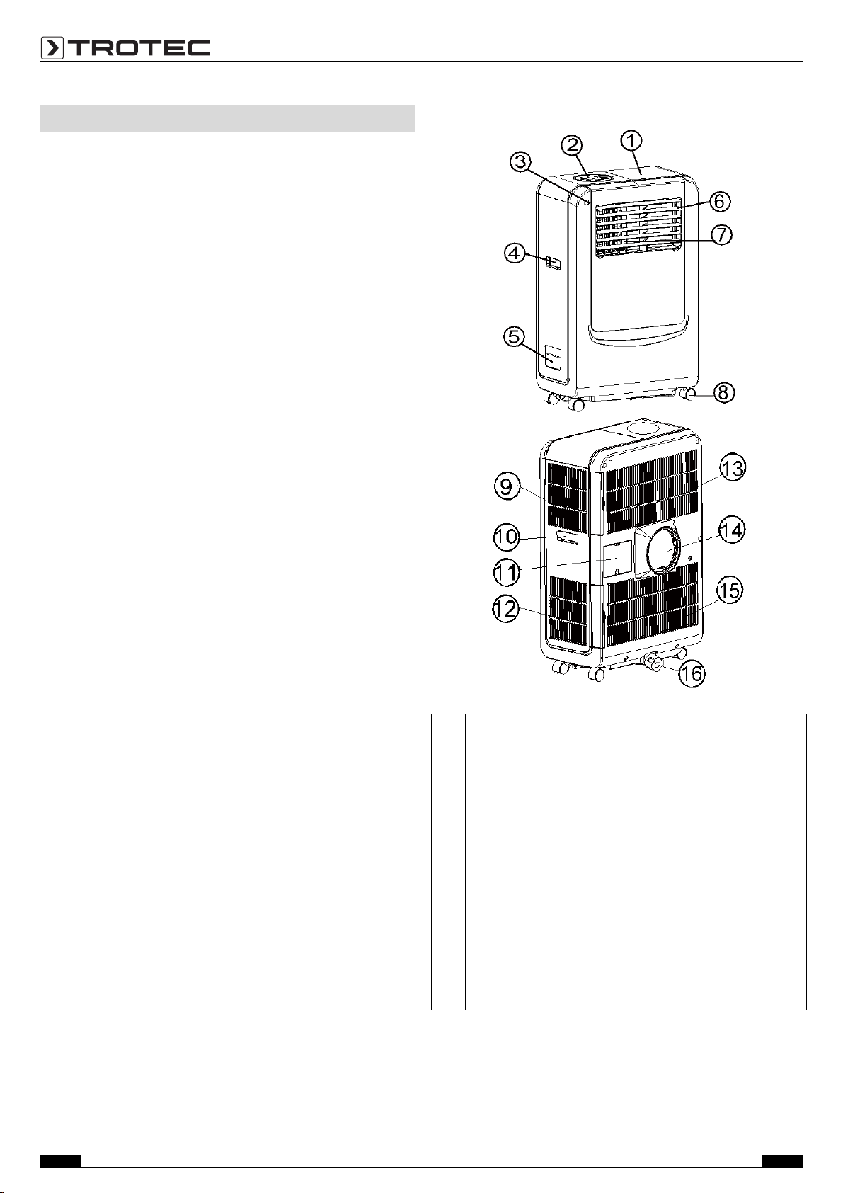
Device depiction
No. Operating element
(1) exhaust air hose storage compartment
(2) control panel
(3) remote control receiver
(4) carrying handle
(5) water funnel
(6) horizontal louvre
(7) vertical louvre
(8) wheel
(9) air filter (air inlet)
(10) carrying handle
(11) cable storage compartment
(12) air filter (air inlet)
(13) air filter (air inlet)
(14) exhaust air outlet
(15) air filter (air inlet)
(16) drain knob / drain hole
2 Operating Manual – Air Conditione r PAC 3500 X EN
Page 5

Accessories
No. Operating element
17 exhaust air hose
18 adapter
to be put on the hose and inserted into window spacer (or into hole in
the wall/window)
19 adapter cover
20 slide 1 - for filling the open window space
21 slide 2 - for filling the open window space
22 slide 3 - for filling the open window space and with hole for connection
to exhaust air hose
23 drain tube for continuous drainage
24 remote control (batteries not included in the scope of delivery)
25 screw driver (to unscrew the top slide)
Technical data
Parameter Value
Model PAC 3500 X
Cooling capacity 3.4 kW
Dehumidifying capacity, max. 1.5 l/h
Surrounding conditions 18 to 32 °C
Air flow rate, max.
Electric connection 220-240 V AC, 50 Hz
Power input, max. 1300 W / 6.0 A
Cooling agent R-410A
Amount of cooling agent 500 g
Timer 1 to 24 hours
Exhaust air hose ø 142 x 1500 mm
Weight 26 kg
Dimensions (WxLxH) 480 mm x 313 mm x 744 mm
Minimum distance
from walls or other objects
Note:
• Measuring condition for the above specifications is according
to EN 14511:
– temperature of dry bulb (room temperature) = 35°C
– temperature of wet bulb (relative humidity) = 24°C
• Test condition for the data on the nameplate is as per safety
regulation: EN 60335-2-40
3
360 m
/h
A: Top: 50 cm
B: Rear: 50 cm
C: Side: 50 cm
D: Front: 50 cm
Safety
Carefully read the operating manual before using the device and keep it within reach!
• Do not use the device in potentially explosive rooms.
• Do not use the device in atmospheres containing oil, sulphur,
chlorine or salt.
• Set the device in an upright and stable position.
• Let the device dry out after a wet clean. Do not operate it
when wet.
• Ensure that the air inlet and outlet are not obstructed.
• Ensure that the side of the device where the air inlet is found
is kept free of dirt and loose objects.
• Never insert objects into the device.
• Do not cover or transport the device during operation.
• Ensure that all electric cables outside of the device are
protected from damage (e.g. from animals).
• Only use extensions to the connecting cable which are
appropriate to the device power consumption, the length of
its cable and its use. Avoid electrical overload.
• Only transport the device in an upright position with an
emptied condensation tank or condensation drain hose.
• Dispose of the collected condensation. Do not drink it. There
is a risk of infection!
• Do not remove any safety signs, stickers or labels from the
device. Keep all safety signs, stickers and labels in legible
condition.
• Observe the storage and operating conditions (see chapter
Technical data).
Intended use
Only use the device for cooling, ventilating and dehumidifying
room air in closed rooms, while adhering to and following the
technical data.
Improper use
Do not place the device on damp or flooded ground. Do not use
the device outdoors. Do not place any objects, e.g. wet clothing,
on the device for drying. Any unauthorised changes,
modifications or alterations of the device are forbidden.
EN Operating Manual – Air Conditioner PAC 3500 X 3
Page 6

Personnel qualifications
CC
A
B
D
People who use this device must:
• be aware of the dangers that occur when working with
electric devices in damp areas.
• have read and understood the operating manual, especially
the Safety chapter.
Residual risks
Hazardous electric voltage!
Work on the electrical components must only be
carried out by an authorised specialist company!
Hazardous electric voltage!
Before any work on the device, remove the mains plug
from the mains socket!
Danger!
Do not leave the packaging lying around. Children may
use it as a dangerous toy.
Danger!
Dangers can occur at the device when it is used by
untrained people in an unprofessional or improper way.
Observe the personnel qualifications.
Operation
• Avoid open doors and windows.
• Do not exceed the recommended room size.
• Keep curtains and venetian blinds closed during the sunniest
time of the day.
• Keep the filter clean.
• Reduce the temperature and ventilation settings as soon as
the room has reached the desired ambient conditions.
Installation of the device
When positioning the device, observe the minimum distance from
walls or other objects as described in the chapter Technical data.
Caution!
To avoid damages to the device, never operate the device
without an air filter inserted!
Transport and storage
Transport
To make the device easier to transport, it is fitted with wheel.
Before transporting the device, proceed as follows:
1. Switch off the device.
2. Remove the mains plug from the mains socket. Do not use the power cable to drag the device!
3. Empty the water tank.
Storage
Empty the condensation tank (see chapter Maintenance).
When the device is not being used, observe the following storage
conditions:
•dry,
• protected from dust and direct sunlight,
• with a plastic cover to protect it from invasive dust, if
necessary.
• Set the device up in a level, upright and stable position.
• Do not create tripping hazards when laying the power cable
or other electric cables.
• Make sure that no curtains or other objects interfere with the
air flow.
• Ensure that extension cords are completely unrolled.
4 Operating Manual – Air Conditione r PAC 3500 X EN
Page 7

Connecting the exhaust air hose
Unscrew this screw here.
1. Unscrew the slide at the top of the device.
2. Remove the slide at the top.
• Only use the supplied hose and fasten the exhaust air hose
and adaptor to the back of the air conditioner.
• Avoid kinks and bends in the exhaust air hose as this will lead
to accumulation of emitted humid air causing the device to
overheat and shut down.
• The hose may be extended from 300 mm to 1500 mm, but
maximum efficiency can only be achieved using the shortest
length.
3. Extract the exhaust air hose.
• The length of the exhaust air hose is especially designed
according to the product specifications. Do not replace or
prolong it with different hoses as this could cause a
malfunction.
4. Connect the exhaust air hose to the air outlet at the rear of the device.
5. Please follow these steps in reverse order to store the exhaust air hose. Do not forget to retighten the screw!
EN Operating Manual – Air Conditioner PAC 3500 X 5
Page 8

Discharge of exhaust air
wall or window
outward adaptor
Using the extendable slide
• Fix the window spacer in the window gap and adjust the
length as needed.
• Feed the exhaust air hose through the window spacer and
close the window until the spacer is held securely. This
technique may also be used for sash windows.
Note:
Ensure protection against intruders.
Using the adaptor
• Feed the exhaust air hose through the window or wall and
attach the threaded adaptor from the outside as depicted.
• When not in use, plug the hole with the provided cover.
Start-up
• Prior to initial start-up, the batteries (2 x type AAA, not
included in the scope of delivery) must be inserted in the
remote control.
– To do so, open the cover of the battery compartment at the
back of the remote control.
– Insert the batteries observing the correct polarity. Go by the
marking inside the battery compartment.
– Then close the battery compartment.
• Check air inlets and outlets for foreign objects and remove
these, if necessary.
• Check the air filter for dirt and clean it, if required. Also see
chapter Maintenance.
• Cut a hole with a diameter of 152 mm into the wall or
window.
6 Operating Manual – Air Conditione r PAC 3500 X EN
Page 9

Adjusting the air vent
• Before using the device, please open the horizontal louver!
Automatic operation
In automatic mode, the device can either cool or ventilate
depending on the ambient temperature and nominal value
settings. The device is preset as follows:
– Default settings in automatic mode:
If the ambient temperature amounts to more than 25°C the
device automatically operates in cooling mode. Default
setting 24°C. During this operation, the following LEDs light
up in green:
– With an ambient temperature of less than or equal to (≤)
25°C the device automatically works in ventilation mode.
The following LEDs light up in green:
–Example:
If you set the nominal value to 24°C the device starts
cooling at 27°C (set value + 3°C). It cools the air down to
25°C (set value + 1°C) and then switches back to
ventilation mode.
• Adjust the louvers to the desired position.
Switch-on of the device
1. Insert the mains plug into a properly secured mains power socket.
2. Open the horizontal louver.
3. Use the power button (A) to switch the device on.
– The device starts in automatic operation mode (AUTO).
– To prolong the compressor lifetime, wait for at least 3
minutes after switch-off before switching the device back
on.
– The cooling system switches off automatically when the
ambient temperature falls below the set one. The fan,
however, keeps running at the set level. If the ambient
temperature rises above the selected level, the cooling will
switch on again.
EN Operating Manual – Air Conditioner PAC 3500 X 7
Page 10

Control panel
No. Designation Function
A Power Power button
B Operating mode
C Timer
D Temperature control down
E Temperature control up
F Sleep Sleep function
G Fan speed
H Ionizer/TiO2 optional, only applies to models with ionizer/TiO2 function
I Display window
1 Water level indicator light
2 Compressor operation indicator light
3 AUTO mode indicator light
4 Cooling mode indicator light
5 Fan mode indicator light
6 Dehumidification (drying) mode indicator light
7 Heating mode indicator light only applies to models with heating function
8 Timer indicator light
9 Ionizer/TiO2 indicator light only applies to models with ionizer/TiO2 function
10 High fan speed indicator light
11 Medium fan speed indicator light
12 Low fan speed indicator light
13 Sleep indicator light
8 Operating Manual – Air Conditione r PAC 3500 X EN
Page 11

Setting the operating mode
• To set the required operating mode, press the Operating
mode button (B):
–cooling,
– ventilation or
– dehumidification (drying).
• The indicator light of the operating mode you selected is
illuminated.
Setting the temperature
• Use the temperature control buttons (up (E) or down (D)) to
set the desired temperature.
• The display window will show the temperature you set as you
press these buttons. Otherwise, it will always show the
ambient temperature.
• The preset temperature value of this device is 24°C for
cooling operation.
Setting the fan speed
• Choose from the 3 available speed levels by pressing the
button Fan speed (G).
– The indicator lights for high (10) and low (12) fan speed are
lit simultaneously.
Setting the timer
• Press the Time button (C) to set the desired operating time.
– 1 to 24 hours, indicated by the corresponding indicator
light.
– When the set time has been reached, the device will switch
off automatically.
– While pressing the Timer button (C), the display window
will show the number of hours you set.
– If the timer function is not activated, the device will work
continuously.
• If you activate the timer without selecting other functions, you
can set the time period after which the device begins to
operate.
– Consequently, if you set the timer to say 2, the device will
automatically start to work after 2 hours.
Sleep function
Note:
The sleep control function is only available in cooling mode.
• If you press the Sleep button (F) during cooling operation, the
set temperature will increase by 1°C in the first hour, by
another in the second and then remain constant.
• In sleep mode the only available fan speed is low.
• Press the Sleep button (F) again to reset the temperature and
fan speed settings.
Dehumidification operation (drying)
• The temperature cannot be regulated during
dehumidification operation, the fan speed is low.
• In dehumidification (drying) mode humidity is extracted from
the air and collected in an internal tank.
• As soon as the tank's maximum filling level is reached,
compressor and motor shut down automatically. The water
level indicator light (1) lights up simultaneously. There will
also be an acoustic alarm.
• Drain the water tank, when it is full. See Emptying the
condensation tank on page 14.
• It is also possible to use the device without having to empty
the tank so often by means of continuous drainage. See
Continuous drainage on page 10.
EN Operating Manual – Air Conditioner PAC 3500 X 9
Page 12

Continuous drainage
30
31
30
31
32
32
33
If you want to operate the device without the having to empty the
condensation tank as often, please proceed as follows:
1. Remove drain knob (31) and rubber plug (30) and retain them for future use.
3. The drain pipe (32) can be extended by adding an extension tube (33) and using a suitable connector.
Notes:
• The drain must be at a lower level than the drain hole of the
device.
• The water level indicator light (1) will be inactive in this
drainage mode.
• If you want to extend the water tube, you can connect it to
another hose (OD: 18 mm).
2. Connect the supplied drain pipe (32) to the water outlet as depicted and put the other end into a drain.
Self-diagnosis
• This device is equipped with a self-diagnosis function.
• In case of a fault E1 or E2 will be indicated on the display.
• In such an event please contact the TROTEC
®
customer
service.
Remote control
All settings of the device can also be made using the remote
control included in the scope of delivery. Please gather the button
functions from the Control panel paragraph.
10 Operating Manual – Air Conditioner PAC 3500 X EN
Page 13

Energy saving
(5)
The device comes with an energy efficiency boosting function.
The energy efficiency can be enhanced by adding 1 l of water via
the water funnel (5) at the side of the device.
Shutdown
1. Use the power button (A) to switch the device off.
2. Remove the mains plug from the mains socket.
3. Clean the device, and especially the air filter, according to chapter Maintenance.
4. Store the device according to chapter Storage.
Errors and faults
The accurate functionality of the device was tested during
production a number of times. However, if functionality faults do
occur, then check the device according to the following list.
• Check the positioning of the air vent. It should be opened to
the maximum.
• Check the air filter for dirt. If required, clean the air filter (see
chapter Maintenance).
• Check the minimum distance to walls or other objects.
Position the device a little more in the room's centre, if
required.
• Check whether there are opened windows and/or doors of
the room. Close these, if any. The window for the exhaust air
hose has to remain open nonetheless.
• Check the temperature setting at the device. Reduce the set
temperature, if it is higher than the room temperature.
The device is loud or vibrates; condensate is leaking:
• Check whether the device is standing upright and on an even
surface.
• Check the stopper of the condensate drain for proper fit or
damage. Plug the stopper in correctly or replace it as
appropriate.
The device does not respond to the infrared remote control
• Check whether the distance between remote control and
device is too big and minimize it, if necessary.
• Check the charging status of the batteries and change them,
if required.
• If the batteries have only just been changed, check them for
correct polarity.
The compressor is not running
• This might be due to the compressor's overheating
protection. Simply wait for the temperature to drop.
The device does not start:
• Check the power connection (230 V~/50 Hz).
• Check the mains plug for damages.
• Observe the operating temperature of 18 to 32 °C.
• Check whether the water level indicator light (1) is lit. If
required, empty the condensation tank (see chapter
Maintenance).
• Have the electrics checked by a specialist company for
cooling and air-conditioning or by TROTEC
®
.
The device works with reduced or no cooling capacity:
• Check whether the cooling operating mode is selected.
• Check the proper fit of the exhaust air hose. In case of kinks,
bends or blockage in the hose, exhaust air cannot be
discharged. Clear the way for the exhaust air.
Your device still does not operate correctly after these checks?
Bring the device to a specialist company for cooling and
air-conditioning or to TROTEC
®
for repairs.
EN Operating Manual – Air Conditioner PAC 3500 X 11
Page 14

Maintenance
Maintenance intervals
Maintenance and care interval
empty condensation tank x
check air inlets and outlets for dirt and foreign
objects and clean if necessary
clean housing xx
visually check the inside of the device for dirt xx
check air inlet grid and air filter for dirt
and foreign objects and clean or replace if necessary
replace air filter x
check for damages x
check attachment screws xx
carry out a test run x
before every
start
x
xx
when necessary
at least every 2
weeks
at least every 4
weeks
at least every 6
months
at least annually
Maintenance and care log
Device type: ............................ Device number: .......................................
Maintenance and care interval 12345678910111213141516
check air inlets and outlets for dirt and foreign
objects and clean if necessary
clean housing
visually check the inside of the device for dirt
check air inlet grid and air filter for dirt and foreign
objects and clean or replace if necessary
replace air filter
check for damages
check attachment screws
carry out a test run
1. Date: ..........................................
Signature:.......................................
5. Date: ..........................................
Signature:.......................................
9. Date: ..........................................
Signature:.......................................
13. Date: ........................................
Signature:.......................................
2. Date:..........................................
Signature: ......................................
6. Date:..........................................
Signature: ......................................
10. Date:........................................
Signature: ......................................
14. Date:........................................
Signature: ......................................
3. Date: ..........................................
Signature:.......................................
7. Date: ..........................................
Signature:.......................................
11. Date: ........................................
Signature:.......................................
15. Date: ........................................
Signature:.......................................
4. Date: ..........................................
Signature: ......................................
8. Date: ..........................................
Signature: ......................................
12. Date: ........................................
Signature: ......................................
16. Date: ........................................
Signature: ......................................
12 Operating Manual – Air Conditioner PAC 3500 X EN
Page 15

Activities required before starting maintenance
• Do not touch the mains plug with wet or damp hands.
• Before any work, detach the mains plug!
Maintenance tasks which require the housing to be
opened must only be carried out by specialist
companies for cooling and air-conditioning or by
TROTEC
®
.
Visual check for dirt in the inside of the device
1. Remove the air filter.
2. Shine a torch through the opening of the device.
3. If you see a thick layer of dust, have the inside of the device
cleaned by a specialist company for cooling and
air-conditioning or by TROTEC
4. Put the air filter back in.
®
.
Cleaning the housing
Clean the device with a soft, damp and lint-free cloth. Ensure that
no moisture enters the housing. Do not use any sprays, solvents,
alcohol-based cleaning agents or abrasive cleaners. Only use
clean water to moisten the cloth.
Refrigerant circuit
• The entire refrigerant circuit is a maintenance-free,
hermetically sealed system and may only be maintained or
repaired by specialist companies for cooling and
air-conditioning or by TROTEC
®
.
EN Operating Manual – Air Conditioner PAC 3500 X 13
Page 16

Emptying the condensation tank
42
40
41
A.
B.
1. Switch the air conditioner off and avoid moving it with full tank.
2. Place a vessel (e.g. a water collection pan) underneath the drain hole (40).
3. Remove the drain knob (42) and the rubber plug (41) from the drain hole (40) and drain the water.
4. When the collection container is almost full, put the rubber plug (41) back into the drain hole (40) and empty the container.
5. Repeat this procedure until the device is completely empty.
6. Plug the rubber plug (41) back in and fasten the drain knob (42).
7. Switch the device on.
– The water level or compressor operation indicator should
not be flashing.
Cleaning the air inlets and the air filter
Caution!
Ensure that the air filter is not worn or damaged. The
corners and edges of the air filter must not be rounded or
misshaped. Before reinserting the air filter, ensure that it
is dry and is not damaged!
Read the chapter Maintenance intervals and replace the
air filter in due time!
14 Operating Manual – Air Conditioner PAC 3500 X EN
Page 17

Disposal Declaration of conformity
In the European Union, electronic equipment must not
be treated as domestic waste, but must be disposed of
professionally in accordance with Directive
2002/96/EC of the European Parliament and Council of 27th
January 2003 concerning old electrical and electronic equipment.
At the end of its life, please dispose of this instrument in a manner
appropriate to the relevant legal requirements.
in accordance with the EC Low Voltage Directive 2006/95/EC and
the EC Directive 2004/108/EC about electromagnetic
compatibility.
Herewith, we declare that the PAC 3500 X was developed,
constructed and produced in compliance with the named EC
directives.
The marking is found on the rear of the device.
Manufacturer:
Trotec GmbH & Co. KG
Grebbener Straße 7
D-52525 Heinsberg
Phone: +49 2452 962-400
Fax: +49 2452 962-200
E-mail: info@trotec.com
Heinsberg, 31/03/2014
Managing Director: Detlef von der Lieck
EN Operating Manual – Air Conditioner PAC 3500 X 15
Page 18

Page 19

Page 20

Trotec GmbH & Co. KG
Grebbener Str. 7
D-52525 Heinsberg
+49 2452 962-400
+49 2452 962-200
info@trotec.com
www.trotec.com
 Loading...