

Page 1
PAC 2010 E / PAC 2610 E
EN
OPERATING MANUAL
LOCAL AIR CONDITIONER
TRT-BA-PAC2010E-PAC2610E-TC-001-EN
Page 2
Table of contents
Notes regarding the operating manual................................. 1
Safety .....................................................................................2
You can download the current version of the operating manual
and the EU declaration of conformity via the following link:
Information about the device................................................4
Transport and storage...........................................................5
Assembly and installation.....................................................5
Operation .............................................................................10
Errors and faults..................................................................16
Maintenance ........................................................................18
Technical annex...................................................................22
Disposal ...............................................................................25
Notes regarding the operating manual
Symbols
Warning of electrical voltage
This symbol indicates dangers to the life and health of
persons due to electrical voltage.
Warning
This signal word indicates a hazard with an average
risk level which, if not avoided, can result in serious
injury or death.
Caution
This signal word indicates a hazard with a low risk
level which, if not avoided, can result in minor or
moderate injury.
PAC 2010 E
http://hub.trotec.com/?id=40010
PAC 2610 E
http://hub.trotec.com/?id=40011
Legal notice
This release replaces all previous versions. No part of this
publication may be reproduced without written permission from
TrotecGmbH&Co.KG. The same applies for electronically
processing, duplicating or spreading the publication. Subject to
technical changes. All rights reserved. Trademarks are used
without guarantee that they may be used freely and primarily
following the spelling of the manufacturer. Product names are
registered.
Changes to construction in the interests of constant
improvements to the product, as well as changes to the shape
and colour are reserved.
The scope of delivery may vary from product images. This
document was created with all due care.
TrotecGmbH&Co.KG accepts no liability whatsoever for
possible mistakes or omissions.
© TrotecGmbH&Co.KG
Notice
This signal word indicates important information (e.g.
material damage), but does not indicate hazards.
Info
Information marked with this symbol helps you to carry
out your tasks quickly and safely.
Follow the manual
Information marked with this symbol indicates that the
operating manual must be observed.
1 EN
Operating manual – local air conditioner PAC 2010 E / PAC 2610 E
Page 3
Warranty and liability
The device complies with the fundamental health and safety
requirements of the applicable EU regulations and was tested at
the factory for perfect functionality multiple times.
However, if faults in the functionality occur and cannot be
remedied with the measures in the chapter Errors and faults,
please get in touch with your dealer or distributor.
When making a warranty claim, supply the device number (see
label on the device).
When manufacturer's instructions or legal regulations have not
been followed, or after unauthorised changes to the device are
made, the manufacturer is not responsible for the resulting
damages. Changes to the device or unauthorised replacement
of individual parts can drastically impact the electrical safety of
this product and will result in the loss of the warranty. Liability
does not extend to damages to people or property caused by the
device being used other than as described in the instructions in
this operating manual. Subject to changes to technical design
and model changes as part of constant development and
product improvement without prior notice.
No liability is accepted for damages resulting from improper
use. In such a case, any warranty claims will be voided also.
Safety
Read this manual carefully before starting or using the
device. Always store the manual in the immediate vicinity
of the device or its site of use!
Warning
Read all safety warnings and all instructions.
Failure to follow the warnings and instructions may
result in electric shock, fire and/ or serious injury.
Save all warnings and instructions for future
reference.
This appliance can be used by children aged from 8
years and above and persons with reduced physical,
sensory or mental capabilities or lack of experience
and knowledge if they have been given supervision or
instruction concerning use of the appliance in a safe
way and understand the hazards involved.
Children shall not play with the appliance. Cleaning and
user maintenance shall not be made by children
without supervision.
• Do not use the device in potentially explosive rooms.
• Do not use the device in aggressive atmosphere.
• Set the device up in an upright and stable position.
• Let the device dry out after a wet clean. Do not operate it
when wet.
• Do not use the device with wet or damp hands.
• Do not expose the device to directly squirting water.
• Never insert any objects or limbs into the device.
• Do not cover or transport the device during operation.
• Do not sit on the device.
• This appliance is not a toy! Keep away from children and
animals. Do not leave the device unattended during
operation.
• Check accessories and connection parts for possible
damage prior to every use of the device. Do not use any
defective devices or device parts.
• Ensure that all electric cables outside of the device are
protected from damage (e.g. caused by animals). Never
use the device if electric cables or the power connection
are damaged!
• The electrical connection must correspond to the
specifications in chapter Technical data.
• Insert the mains plug into a properly secured mains
socket.
• Observe the technical data when selecting extensions to
the power cable. Completely unroll the extension cable.
Avoid electrical overload.
• Before carrying out maintenance, care or repair work on
the device, remove the mains plug from the mains socket.
Hold onto the mains plug while doing so.
EN 2
Operating manual – local air conditioner PAC 2010 E / PAC 2610 E
Page 4
• Switch the device off and disconnect the power cable from
the mains socket when the device is not in use.
• Do not under any circumstances use the device if you
detect damages on the mains plug or power cable.
If the supply cord is damaged, it must be replaced by the
manufacturer, his service agent or similarly qualified
persons in order to avoid a hazard.
Defective power cables pose a serious health risk.
• Observe the storage and operating conditions (see chapter
Technical data).
• Ensure that the air inlet and outlet are not obstructed.
• Ensure that the side of the device where the air inlet is
found is kept free of dirt and loose objects.
• Only transport the device in an upright position with an
emptied condensation tank or drain hose.
• Discharge the collected condensate before transport and
storage. Do not drink it. Health hazard!
Residual risks
Warning of electrical voltage
Work on the electrical components must only be
carried out by an authorised specialist company!
Warning of electrical voltage
Before any work on the device, remove the mains plug
from the mains socket!
Hold onto the mains plug while pulling the power cable
out of the mains socket.
Warning
Dangers can occur at the device when it is used by
untrained people in an unprofessional or improper way!
Observe the personnel qualifications!
Warning
The device is not a toy and does not belong in the
hands of children.
Intended use
Only use the device for cooling, ventilating and dehumidifying
indoor air whilst adhering to the technical data.
Improper use
• Do not place the device on wet or flooded ground.
• Do not place any objects, e.g. clothing, on the device.
• Do not use the device outdoors.
• Any unauthorised modifications, such as alterations or
structural changes to the device, are forbidden.
• Any operation other than as described in this manual is
prohibited. Non-observance renders all claims for liability
and guarantee null and void.
Personnel qualifications
People who use this device must:
• be aware of the dangers that occur when working with
electric devices in damp areas.
• have read and understood the operating manual, especially
the Safety chapter.
Maintenance tasks which require the housing to be opened
must only be carried out by specialist companies for cooling and
air-conditioning or by Trotec.
Warning
Risk of suffocation!
Do not leave the packaging lying around. Children may
use it as a dangerous toy.
Notice
Do not operate the device without an inserted air filter!
Without an air filter the inside of the device will be
heavily contaminated, which could reduce the
dehumidification performance and result in damage to
the device.
Behaviour in the event of an emergency
1. In an emergency, disconnect the device from the mains
feed-in: Switch the device off and disconnect the power
cable from the mains socket. Hold onto the mains plug
while doing so.
2. Do not reconnect a defective device to the mains.
3 EN
Operating manual – local air conditioner PAC 2010 E / PAC 2610 E
Page 5

Information about the device
T-ON T-OFF
COOL
DRY
FAN
X-FAN
SLEEP
LOCK
SPEED
1
10
2
3
3
4
5
6
7
8
9
11
8
Device description
The device serves the purpose of cooling the room air. It further
filters and dehumidifies the air thus creating an agreeable room
climate.
The unit cools the room air by withdrawing warmth. The
absorbed warmth is emitted to the outside via the exhaust air
hose; cooled air is fed to the installation site by means of a fan.
Accumulating condensate drips from the evaporator onto the hot
condenser, there it evaporates and then is transported to the
outside via the exhaust air hose.
In ventilation mode the device provides the opportunity of air
circulation without cooling effect.
In dehumidification mode moisture is withdrawn from the air.
The device comes with a self-cleaning function for internal
drying to prevent mould formation or the likes due to residual
moisture on the inside of the device.
The device operates fully automatically and features a variety of
further options. The device can, for instance, be switched on or
off automatically with time delay via the timer function.
Operation of the device is possible either via the control panel at
the device or via the supplied infrared remote control.
The device was designed for universal and flexible application.
Due to its compact dimensions it can be easily transported and
used in all interior spaces.
Device depiction
EN 4
Operating manual – local air conditioner PAC 2010 E / PAC 2610 E
No. Designation
1 Control panel
2 Air outlet with ventilation flaps
3 Wheels
4 Air inlet with air filter
5 Exhaust air hose connection
6 Remote control
7 Condensate outlet with rubber cap
8 Power cable holder
9 Hose connector with sealing cap and rubber stopper
10 Handle
11 Compartment for remote control
Page 6

Transport and storage
Assembly and installation
Notice
If you store or transport the device improperly, the
device may be damaged.
Note the information regarding transport and storage of
the device.
Transport
Before transporting the device, proceed as follows:
• Switch off the device.
• Hold onto the mains plug while pulling the power cable out
of the mains socket.
• Drain the remaining condensate from the device and the
condensation drain hose (see chapter Maintenance).
• To make the device easier to transport, it is fitted with
wheels.
• Do not use the power cable to drag the device.
• Only wheel the device on a level and smooth surface.
After transporting the device, observe the following:
• Set up the device in an upright position after transport.
• Leave the device to rest for 12-24hours, so the
refrigerant can accumulate within the compressor. Wait
12-24hours before switching the device back on! Acting
contrary might lead to compressor damage and a
malfunctioning device. If so, any warranty claims will be
voided.
Scope of delivery
• 1x device
• 1 x exhaust air hose
• 1x hose adapter
• 1x condensation drain hose, length: 0.3 m,
diameter: 14 mm
• 1x hose connector
• 1x two-part flat nozzle
• 2 x clamping piece
• 1x rubber stopper
• 1x retaining clip
• 1 x remote control
• 2 x power cable holder
• 3 x screw
• 1x manual
Unpacking the device
1. Open the cardboard box and take the device out.
2. Completely remove the packaging.
3. Fully unwind the power cable. Make sure that the power
cable is not damaged and that you do not damage it during
unwinding.
Storage
Before storing the device, proceed as follows:
• Drain the remaining condensate from the device and the
condensation drain hose (see chapter Maintenance).
• Carry out the self-cleaning function to prevent the
formation of moisture within the device during a longer
period of non-use.
When the device is not being used, observe the following
storage conditions:
• dry and protected from frost and heat
• in an upright position where it is protected from dust and
direct sunlight
• with a cover to protect it from invasive dust if necessary
• Place no further devices or objects on top of the device to
prevent it from being damaged.
• Remote batteries from the remote control.
5 EN
Operating manual – local air conditioner PAC 2010 E / PAC 2610 E
Page 7
Assembly
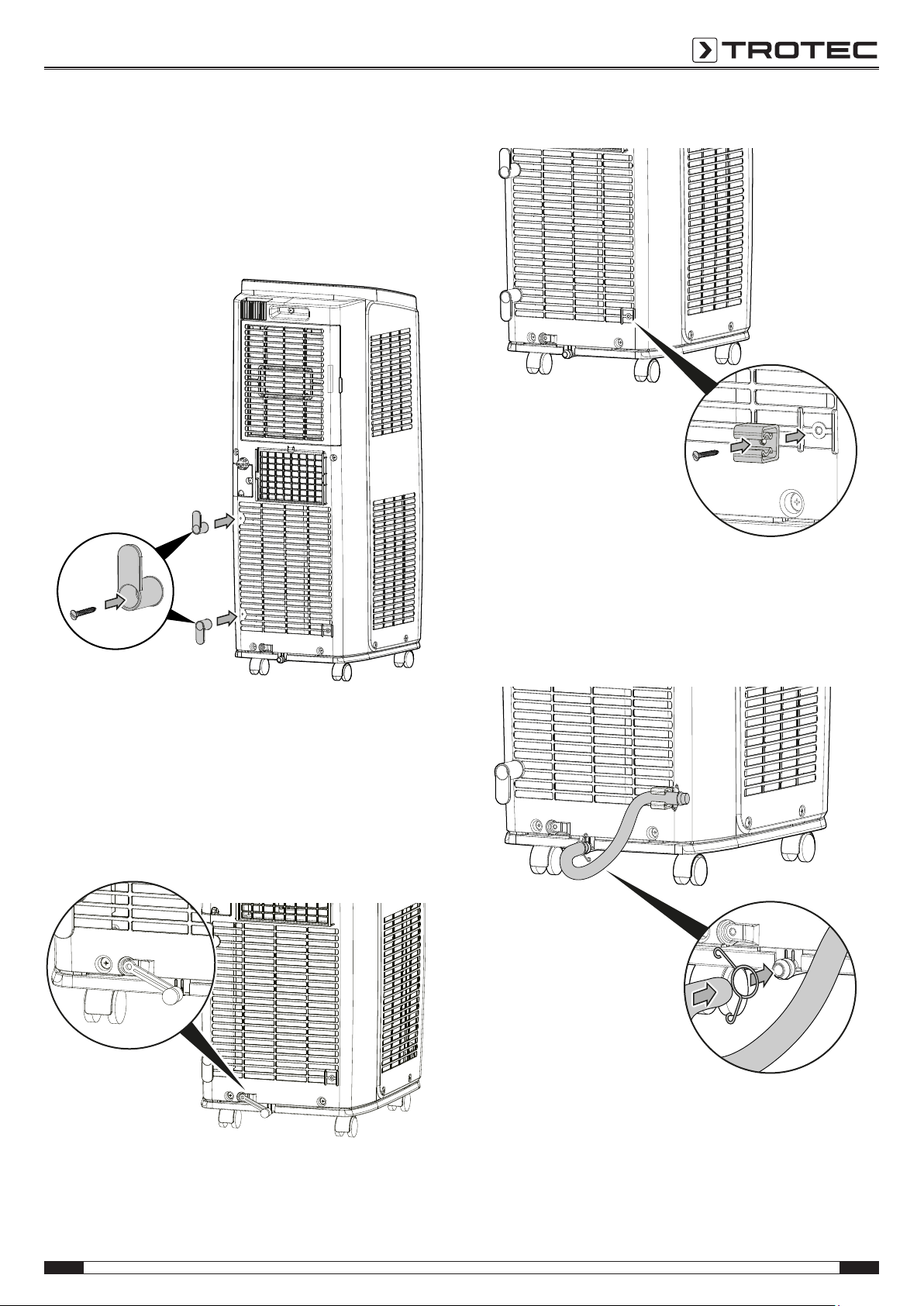
Mounting the power cable holder
1. Assemble the power cable holding fixture by screwing down
the power cable holders at the back of the device.
ð Observe the lug direction of the power cable holder. The
lug of the upper power cable holder points upwards, the
bottom one towards the bottom.
2. Screw the retaining clip to the device.
ð If required, the power cable can be reeled around the
holding fixture.
Mounting the condensation drain hose (optional)
The condensation drain hose serves as drip protection and, if
required, for discharging remaining condensate.
ü The device is switched off.
ü The device is disconnected from the mains.
1. Remove the rubber cap from the condensate outlet.
3. Place one end of the condensation drain hose into the
retaining clip.
4. Push the other end of the condensation drain hose onto the
condensate outlet. Fix the condensation drain hose in place
by means of a clamping piece.
EN 6
Operating manual – local air conditioner PAC 2010 E / PAC 2610 E
Page 8
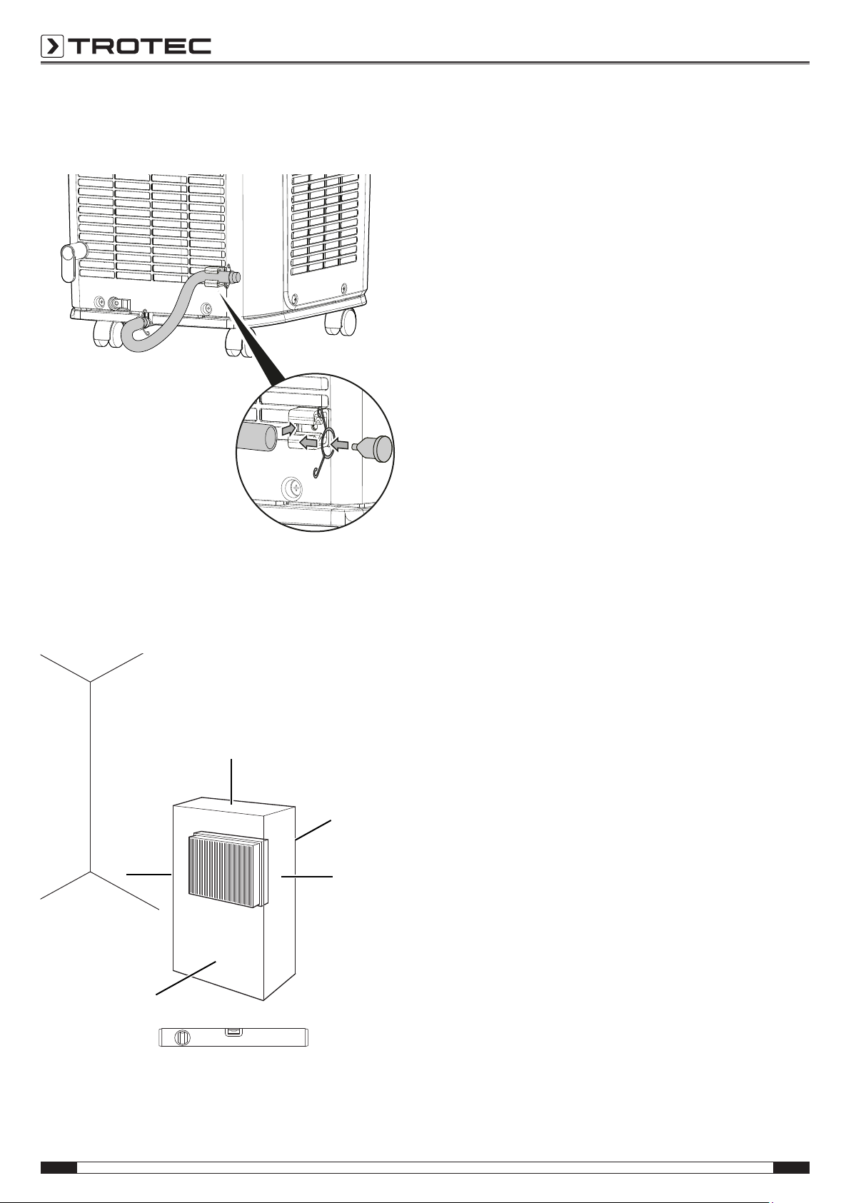
5. Plug the rubber stopper into the other end of the
A
B
C
C
D
condensation drain hose. Secure the rubber stopper by
means of a clamping piece.
• Before restarting the device, check the condition of the
power cable. If there are doubts as to the sound condition,
contact the customer service.
• Set the device up in an upright and stable position.
• Do not create tripping hazards when laying the power
cable or other electric cables, especially when positioning
the device in the middle of the room. Use cable bridges.
• Make sure that extension cables are completely unrolled.
• Keep air inlets and outlets as well as the exhaust air hose
connection free.
• Make sure that no curtains or other objects interfere with
the air flow.
Prior to initial start-up, insert the batteries in the remote control.
Start-up
When positioning the device, observe the minimum distance
from walls or other objects as described in the Technical data
chapter.
7 EN
Operating manual – local air conditioner PAC 2010 E / PAC 2610 E
Page 9

Inserting the air filter
A.
B.
C.
D.
Notice
Do not operate the device without an inserted air filter!
Without an air filter the inside of the device will be
heavily contaminated, which could reduce the
dehumidification performance and result in damage to
the device.
• Make sure that both air filters are installed before
switching the device on.
Connecting the exhaust air hose
1. Assemble the two-part flat nozzle by pushing the top
connection piece onto the bottom one until they click into
place.
in the direction of the arrow.
3. Screw the hose adapter onto the other end of the exhaust
air hose in the direction of the arrow.
4. Insert the hose adapter with exhaust air hose into the air
conditioner's exhaust air hose connection. The side labelled
TOP must face upwards.
2. Screw the flat nozzle onto one end of the exhaust air hose
EN 8
Operating manual – local air conditioner PAC 2010 E / PAC 2610 E
Page 10

Discharging exhaust air
≤130 cm
≥40 cm
• The exhaust air coming from the device contains waste
heat from the room to be cooled. For this reason it is
recommended to discharge the exhaust air to the outside.
• The end of the exhaust air hose can be fed through the
open window. If required, secure the open window with
the corresponding means, so that the end of the exhaust
air hose cannot shift.
• The end of the exhaust air hose can also be hooked into a
tilted window.
For this purpose, we recommend using a window seal
(optional).
• Install the exhaust air hose inclined with the air direction.
Example with exhaust air hose:
For installing the exhaust air hose please observe the following:
• Avoid kinks and bends in the exhaust air hose, as they
would lead to an accumulation of emitted humid air
causing the device to overheat and shut down.
• The dimensions of the exhaust air hose were especially
made to fit the device. Do not replace or extend the hose,
for it could cause a malfunction.
9 EN
Operating manual – local air conditioner PAC 2010 E / PAC 2610 E
Page 11

Opening the ventilation flaps
23
12
13
14
15
16
18
17
19
20
21
22
1. Prior to switching the device on, open the ventilation flaps
at the air outlet.
Connecting the power cable
• Insert the mains plug into a properly secured mains
socket.
Operation
• Avoid open doors and windows.
Operating elements
No. Designation Function
12 Minus arrow button Decreasing the target temperature (16°C
to 30°C) or the number of hours of the
timer (0.5 to 24h).
13 Segment display Indication of the target temperature in
cooling mode
Indication the number of hours during
timer programming
Indication of the error code, see chapter
Errors and faults
°C / °F indication
14 Plus arrow button Increasing the target temperature (16°C
to 30°C) or the number of hours of the
timer (0.5 to 24h).
15 Operating mode LED Indicates the selected operating mode:
Cool = cooling
Dry = dehumidification
Fan = ventilation
16 Mode button Selecting the operating mode:
cooling
dehumidification
ventilation
17 Timer LED Illuminated when the timer is activated
18 Timer button Switching the timer function on and off:
in increments of 0.5hours (0.5 to 10h)
or in increments of 1hour (11 to 24h)
19 On/Off button Power button: Switching the device on
and off
20 Sleep button Switching night mode on and off
21 Sleep LED Illuminated when night mode is activated
22 Fan button Setting the fan stage:
Low = lowest level
Med = medium level
High = highest level
Auto = automatic speed regulation
23 Fan stage LED Indicates the current fan stage
Info
An acoustic signal is emitted each time a setting is
EN 10
Operating manual – local air conditioner PAC 2010 E / PAC 2610 E
activated.
Page 12

Switching the device on
1. Allow the device to rest for a time.
2. Once you have completely installed the device as described
in the Start-up chapter, you can switch it on.
3. Press the On/Off button(19).
ð The device switches on.
4. Select the desired operating mode.
The device switches off automatically when the condensation
tank is full. H8 is displayed on the segment display(13).
Setting the operating mode
Cooling
In cooling mode the room will be cooled down to a certain
preselected temperature.
Upon reaching the target temperature, the device switches to
standby, i.e. the fan keeps running at the preselected level, but
the device does not resume cooling until the preselected value
is exceeded again.
The automatic stage depends on the current room temperature
and the set target temperature. The fan speed increases with a
high room temperature. The fan speed decreases in case of a
low room temperature.
Connecting the condensation hose
If you use the device for an extended period of time or you don't
want to empty the condensation tank all the time, you can
connect the condensation drain hose to the hose connection.
ü The device is switched off.
ü The device is disconnected from the mains.
1. Carefully transport or wheel the device to a suitable location
for discharging the condensate (e.g. a drain) or position a
suitable collection container under the condensate outlet.
2. Unscrew the sealing cap counter-clockwise from the hose
connection(9).
1. Use the Mode button(16) to select cooling mode.
ð The operating mode LED Cool(15) is illuminated.
2. Select the desired target temperature by use of the arrow
buttons(12 or 14). The temperature can be adjusted in
increments of 1°C in a range between 16 °C and 30 °C.
ð The desired target temperature is indicated on the
segment display(13).
3. Select the desired fan stage by use of the Fan button(22).
ð The fan stage LED(23) indicates the desired fan stage.
Dehumidification
In dehumidification mode the humidity level in the room is
reduced.
The temperature cannot be adjusted and the fan runs at the
lowest speed level.
Info
Remove the exhaust air hose during dehumidification,
otherwise the performance will be insufficient.
1. Press the Mode button(16) until the operating mode LED
Dry(15) is illuminated.
3. Remove the rubber stopper from the hose connection.
4. Keep sealing cap and rubber stopper for later use.
Info
If the device is operated in a very humid environment,
the accumulating condensate must be discharged at
regular intervals (see chapter Condensate discharge).
11 EN
Operating manual – local air conditioner PAC 2010 E / PAC 2610 E
Page 13

5. Turn the connector clockwise to screw it onto the hose
connection.
7. Guide the other end of the condensation drain hose to a
suitable drain or sufficiently dimensioned collection
container. To ensure that the condensate can run off, the
hose must not be kinked, nor should it have to overcome an
uphill incline towards the drain.
6. Connect the condensation drain hose.
EN 12
Operating manual – local air conditioner PAC 2010 E / PAC 2610 E
Page 14

Info
If during assembly you mounted the condensation
drain hose at the bottom, you can let the condensate
drain off there.
1. Remove the rubber stopper from the condensation drain
hose.
2. Detach the condensation drain hose from the retaining clip
and guide the hose to a drain or collection container. To
ensure that the condensate can run off, the hose must not
be kinked, nor should it have to overcome an uphill incline
towards the drain.
Ventilation
In ventilation mode the room air is circulated, it will neither be
cooled nor dehumidified.
The automatic stage depends on the current room temperature
and the set target temperature. The fan speed increases with a
high room temperature. The fan speed decreases in case of a
low room temperature.
Setting the timer
The timer has two modes of operation:
• automatic switch-on upon expiry of a preset number of
hours
• automatic switch-off upon expiry of a preset number of
hours
The timer can be programmed in increments of 0.5hours (0.5
to 10h) or in increments of 1hour (11 to 24h).
The function can be set in all operating modes and also during
stand-by.
Notice
Do not leave the operating device unattended in a
freely accessible room with an activated timer.
Automatic switch-on
ü The device is switched off.
1. Press the Timer button(18) to activate the timer.
ð The Timer LED(17) flashes.
ð The segment display(13) indicates the number of hours
until automatic switch-on (default: 0.5).
2. Press the plus/ minus arrow buttons(12, 14) until the
desired number of hours until automatic switch-on has
been set.
ð The number of hours is indicated on the segment
display(13) for approx.5s.
3. Press the Timer button(18) to confirm the desired number
of hours until automatic switch-on.
ð The segment display(13) switches off. The Timer
LED(17) is illuminated.
ð After the predefined time, the device switches itself on.
4. Press the Timer button(18) again to deactivate the timer.
Notes regarding automatic switch-on:
• If the device is disconnected from the power supply, all
settings for automatic switch-on are deleted.
• Manually switching the device on disables the automatic
switch-on function.
• Pressing the Timer button(18) again deactivates the timer.
Info
Remove the exhaust air hose during ventilation.
1. Press the Mode button(16) until the operating mode LED
Fan(15) is illuminated.
2. Press the Fan button(22) to set the fan stage.
ð The fan stage LED(23) for the selected fan stage will be
illuminated.
13 EN
Operating manual – local air conditioner PAC 2010 E / PAC 2610 E
Page 15

Automatic switch-off
°F
OPER
AUTO
°C
T-ON T-OFF
COOL
DRY
FAN
X-FAN
SLEEP
LOCK
SPEED
24
25
26
27
28
29
30
31
32
33
ü The device is switched on.
1. Press the Timer button(18) to activate the timer.
ð The Timer LED(17) flashes.
ð The segment display(13) indicates the number of hours
until automatic switch-off (default: 0.5).
2. Press the plus/ minus arrow buttons(12, 14) until the
desired number of hours until automatic switch-off has
been set.
ð The number of hours is indicated on the segment
display(13) for approx.5s.
3. Press the Timer button(18) to confirm the desired number
of hours until automatic switch-off.
ð The segment display(13) switches off. The Timer
LED(17) is illuminated.
ð The device keeps running until the given switch-off
time has expired.
4. Press the Timer button(18) again to deactivate the timer.
Night mode
The night mode can be activated when in cooling mode. Night
mode comes with the following settings:
• After one hour the preset temperature is increased by 1°C.
After 2hours the preset temperature will again be
increased by 1°C. Then the temperature is kept constant.
Proceed as follows to activate night mode:
1. Select cooling mode.
2. Press the Sleep button(20).
ð The Sleep LED(21) is illuminated.
ð The fan stage will automatically be set to Low.
3. In order to switch the night mode off, press the Sleep
button(20) once again.
ð The Sleep LED(21) goes out.
Remote control
All settings of the device can also be made using the remote
control included in the scope of delivery.
Info
After a longer period of non-use, the remote control
will switch to standby mode. Standby mode can be
terminated by pressing the ON/OFF button(33) on the
remote control. The device automatically uses the
current settings entered via the remote control.
No. Designation Meaning
24 Remote control
transmitter/
receiver
25 Display Indication of the target temperature during
26 MODE button Selection button for the mode of operation
27 Plus button Setting the target temperature for cooling
28 X-FAN button Self-cleaning function / internal drying during
29 TIMER button Switching the timer function on and off: in
30 SLEEP button Switching night mode on and off
31 FAN button Setting the fan stage
32 Minus button Setting the target temperature for cooling
33 ON/OFF button On/Off button: Switching the device on and off
Communication between device and remote
control using infrared
setting
Indication of the number of hours during timer
programming
Indication of the operating mode
Indication of the fan stage
Indication of the self-cleaning function (X-FAN)
Timer on/ off indication
°C / °F indication
Key lock indication
Night mode indication
Setting the number of hours for the timer
function
stand-by
increments of 0.5hours (0.5 to 10h) or in
increments of 1hour (11 to 24h)
Setting the number of hours for the timer
function
Info
An acoustic signal is emitted each time a setting is
activated.
EN 14
Operating manual – local air conditioner PAC 2010 E / PAC 2610 E
Page 16

Changing the unit °C / °F
The temperature can be indicated in either °C or °F on the
remote control's display(25) and on the segment display(13) of
the device.
The temperature unit can only be changed in standby mode.
Please proceed as follows to change the temperature unit:
1. Press the minus(32) and MODE(26) buttons
simultaneously.
ð The displayed temperature is converted to the other unit.
Key lock (remote control only)
The function can be activated via the remote control both during
operation and in standby mode.
The key lock applies to the remote control only – the control
panel at the device is not affected and can be used nonetheless.
1. Simultaneously press the plus/ minus buttons(27, 32) on
the remote control.
ð The key lock is activated. The remote control cannot
send signals to the device.
ð The LOCK indication can be seen on the remote
control's display(25).
2. Simultaneously press the plus/ minus buttons(27, 32) once
more.
ð The key lock is deactivated.
ð The LOCK indication on the remote control's
display(25) disappears.
Switching the control panel illumination on and off
The illumination of the control panel can be switched on or off
via the remote control both during operation and in standby
mode.
1. Simultaneously press the plus button(27) and the FAN
button(31) on the remote control for 3s.
ð The control panel illumination will be switched off.
ð The device continues to run with the selected settings.
2. Simultaneously press the plus button(27) and the FAN
button(31) again for 3s.
ð The control panel illumination will be switched back on.
Self-cleaning function / Internal drying
This function serves to dry the interior of the device in order to
prevent the formation of mould or similar inside the device due
to residual moisture.
The self-cleaning function should be used if the device is not
operated or is stored for a longer period of time.
This function can be activated via the remote control during
cooling and dehumidification.
The fan continues to run at low speed for a while after the
device has been switched off.
Please proceed as follows to activate the self-cleaning function/
internal drying:
1. Select the operating mode cooling or dehumidification.
2. Press the X-FAN button(28) on the remote control.
ð The X-FAN indication can be seen on the remote
control's display(25).
3. Press the ON/OFF button(33) to switch the device off.
ð The fan continues to run at low speed for a while. Then
the fan switches off as well.
4. You can deactivate the self-cleaning function/ internal
drying at any time by pressing the X-FAN button(28) again.
Memory function
After a power failure during operation the device will
automatically be switched back on. The chosen operating mode
settings will be saved, a possibly programmed timer will not.
All the chosen settings (incl. timer) remain saved on the remote
control. As soon as the device receives an input from the remote
control, the settings will be transmitted from the remote control
to the device.
The compressor may start up with a delay of 3min, as it is
provided with an internal protection against direct restart.
Automatic defrost
At low ambient temperatures, ice may form at the evaporator.
The device will then carry out an automatic defrost.
The compressor switches off and the fan keeps running until
defrosting is completed. The duration of the defrost process can
vary.
Do not switch the device off during automatic defrost. Do not
remove the mains plug from the mains socket.
Shutdown
Warning of electrical voltage
Do not touch the mains plug with wet or damp hands.
• Switch off the device.
• Hold onto the mains plug while pulling the power cable out
of the mains socket.
• If necessary, remove the condensation drain hose and any
residual fluid from it.
• Empty the condensation tank, if need be.
• If necessary, carry out self-cleaning (see chapter Selfcleaning function).
• Clean the device according to the Maintenance chapter.
• Store the device according to the Storage chapter.
15 EN
Operating manual – local air conditioner PAC 2010 E / PAC 2610 E
Page 17

Errors and faults
The device has been checked for proper functioning several
times during production. If malfunctions occur nonetheless,
check the device according to the following list.
The device does not start:
• Check the power connection.
• Check the power cable and mains plug for damages.
• Check the on-site fusing.
• Observe the operating temperature according to the
Technical data chapter.
• Check the filling level of the condensation tank and empty
it if necessary. The error codeH8 must not be indicated on
the segment display.
• Wait for 10minutes before restarting the device. If the
device is not starting, have the electrics checked by a
specialist company or by Trotec.
The device works with reduced or no cooling capacity:
• Check whether cooling mode is selected.
• Check the proper fit of the exhaust air hose. In case of
kinks, bends or blockage in the hose, exhaust air cannot
be discharged. Clear the way for the exhaust air.
• Check the position of the ventilation flaps. They should be
opened to the maximum.
• Check the air filter(s) for dirt. If necessary, clean or replace
the air filter(s).
• Check the minimum distance to walls or other objects.
Position the device a little more in the room's centre if
required.
• Check whether any windows and/or doors of the room are
open. If so, close them. The window for the exhaust air
hose has to remain open nonetheless.
• Check the temperature setting at the device. Reduce the
set temperature if it is higher than the room temperature.
The device is loud or vibrates:
• Check whether the device is set up in a stable and upright
position.
Condensate is leaking:
• Check the device for leaks.
The compressor does not start:
• In cooling mode the compressor will only start at a room
temperature of at least 16°C.
• Check whether the overheating protection of the
compressor has tripped. Disconnect the device from the
mains and let it cool down for approx. 10minutes before
reconnecting it.
• Check whether the ambient temperature equals the target
temperature (in cooling mode). The compressor will not
switch on unless the respective temperature is reached.
• The compressor may start up with a delay, as it is provided
with an internal protection against direct restart.
The device gets very warm, is loud or loses power:
• Check the air inlets and air filter for dirt. Remove external
dirt.
• From the outside, check the device for dirt (see chapter
Maintenance). If the inside of the device is dirty, have it
cleaned by a specialist company for cooling and airconditioning or by Trotec.
The device does not respond to the infrared remote control:
• Check whether the distance between remote control and
device is too large and reduce it if necessary.
• Make sure there are no obstacles, such as furniture or
walls, between the device and the remote control. Ensure
visual contact between device and remote control.
• Check the charging status of the batteries and change
them if required.
• If the batteries have only just been changed, check them
for correct polarity and change them if required.
• After a longer period of non-use, the remote control will
switch to standby mode. Standby mode can be terminated
by pressing the ON/OFF button(33) on the remote control.
Notice
Wait for at least 3 minutes after maintenance and
repair work. Only then switch the device back on.
Your device still does not operate correctly after these
checks?
Please contact the customer service. If necessary, bring the
device to a specialist company for cooling and air-conditioning
or to Trotec for repair.
EN 16
Operating manual – local air conditioner PAC 2010 E / PAC 2610 E
Page 18

Error codes
The following error messages can be displayed on the segment
display(13):
Error code Cause Remedy
F0 Leaking cooling agent Disconnect the device from the
System blocked
F1 Defective room
temperature sensor
F2 Defective temperature
sensor of evaporator
F4 Defective exhaust air
temperature sensor
H3 Tripped overload
protection of compressor
E8 Malfunction due to
overload
H8 Condensation tank full Discharge condensate (manual
mains for approx. 30min.
Should the error still be displayed
after the restart, please contact
the customer service.
Please contact the customer
service.
Check whether the ambient
conditions are outside the range
specified in the technical data.
Wait until temperature and
humidity level are back within the
operating range before switching
the device back on.
Check whether air inlet and outlet
are obstructed by any objects and
remove these before switching
the device back on.
Should the error still be displayed,
please contact the customer
service.
draining) according to the
Maintenance chapter.
17 EN
Operating manual – local air conditioner PAC 2010 E / PAC 2610 E
Page 19

Maintenance
Maintenance intervals
Maintenance and care interval before every
start-up
Empty condensation tank and drain hose X
Check the air inlets and outlets for dirt and
foreign objects and clean if necessary
Clean the exterior X X
Visually check the inside of the device for
dirt
Check the air filter for dirt and foreign
objects and clean or replace if necessary
Replace air filter X
Check for damage X
Check the attachment screws X X
Test run X
X X
X X
as needed at least every 2
weeks
X X
at least every 4
weeks
at least every 6
months
at least annually
Maintenance and care log
Device type: .............................................
Maintenance and care interval 1 2 3 4 5 6 7 8 9 10 11 12 13 14 15 16
Empty condensation tank and drain hose
Check the air inlets and outlets for dirt and
foreign objects and clean if necessary
Clean the exterior
Visually check the inside of the device for
dirt
Check the air filter for dirt and foreign
objects and clean or replace if necessary
Replace air filter
Check for damage
Check the attachment screws
Test run
Remarks:
Device number: ....................................
1. Date: ................................
Signature: ............................
5. Date: ................................
Signature: ............................
9. Date: ................................
Signature: ............................
13. Date: ..............................
Signature: ............................
EN 18
2. Date: ................................
Signature: ............................
6. Date: ................................
Signature: ............................
10. Date: ..............................
Signature: ............................
14. Date: ..............................
Signature: ............................
Operating manual – local air conditioner PAC 2010 E / PAC 2610 E
3. Date: ................................
Signature: ............................
7. Date: ................................
Signature: ............................
11. Date: ..............................
Signature: ............................
15. Date: ..............................
Signature: ............................
4. Date: ................................
Signature: ............................
8. Date: ................................
Signature: ............................
12. Date: ..............................
Signature: ............................
16. Date: ..............................
Signature: ............................
Page 20

Activities required before starting maintenance
Warning of electrical voltage
Do not touch the mains plug with wet or damp hands.
• Switch off the device.
• Hold onto the mains plug while pulling the power cable out
of the mains socket.
Warning of electrical voltage
Tasks which require the housing to be opened
must only be carried out by authorised specialist
companies or by Trotec.
Cleaning the housing
Clean the device with a soft, damp and lint-free cloth. Ensure
that no moisture enters the housing. Protect electrical
components from moisture. Do not use any aggressive cleaning
agents such as cleaning sprays, solvents, alcohol-based or
abrasive cleaners to dampen the cloth.
Visual inspection of the inside of the device for dirt
1. Remove the air filter.
2. Use a torch to illuminate the openings of the device.
3. Check the inside of the device for dirt.
4. If you see a thick layer of dust, have the inside of the device
cleaned by a specialist company for cooling and airconditioning or by Trotec.
5. Put the air filter back in.
19 EN
Operating manual – local air conditioner PAC 2010 E / PAC 2610 E
Page 21

Cleaning the air filter
The air filters have to be cleaned as soon as they are dirty. This
is brought to light e.g. by a reduced capacity (see chapter Errors
and faults).
Warning
Ensure that the air filters are neither worn nor
damaged. The corners and edges of the air filters must
not be deformed or rounded. Before reinserting the air
filters, make sure that they are undamaged and dry!
1. Remove the air filters from the device.
2. Clean the filters using a slightly damp, soft, lint-free cloth. If
the filters are heavily contaminated, clean them with warm
water mixed with a neutral cleaning agent.
3. Allow the filters to dry completely. Do not put any wet filters
into the device!
4. Reinsert the air filters into the device.
EN 20
Operating manual – local air conditioner PAC 2010 E / PAC 2610 E
Page 22

Condensate discharge (manual draining)
In cooling and dehumidification mode condensate is formed,
which is mostly discharged via the exhaust air.
The remaining condensate is collected in a container within the
housing. The condensate ought to be drained regularly.
If too much condensate accumulates, the device switches off
and indicates this via the H8 indication on the segment
display(13).
1. Carefully transport or wheel the device to a suitable location
for discharging the condensate (e.g. a drain) or position a
suitable collection container underneath the lower
condensate outlet.
2. Remove the rubber stopper from the condensation drain
hose.
3. Detach the condensation drain hose from the retaining clip
and guide the hose to a drain or collection container. To
ensure that the condensate can run off, the hose must not
be kinked, nor should it have to overcome an uphill incline
towards the drain.
5. Reattach the rubber stopper to the condensation drain hose
and put the hose back into the retaining clip. Ensure the
tight fit of the rubber stopper, for otherwise there might be
uncontrolled water leakage.
ð The H8 error code on the segment display(13) will
disappear as soon as the condensate has been drained.
Refrigerant circuit
• The entire refrigerant circuit is a maintenance-free,
hermetically sealed system and may only be maintained or
repaired by specialist companies for cooling and airconditioning or by Trotec.
Activities required after maintenance
If you want to continue using the device:
• Leave the device to rest for 12-24hours, so the
refrigerant can accumulate within the compressor. Wait
12-24hours before switching the device back on! Acting
contrary might lead to compressor damage and a
malfunctioning device. If so, any warranty claims will be
voided.
• Reconnect the device to the mains.
If you do not intend to use the device for a considerable time:
• Store the device according to the Storage chapter.
4. Let the condensate run, until the condensation drain hose is
completely drained.
21 EN
Operating manual – local air conditioner PAC 2010 E / PAC 2610 E
Page 23

Technical annex
WATER MOTOR
ROOM
POWER
L
BN(BK)
N
YEGN(GN)
BU(WH)
BU
N3
S
COMP
YEGN
C
YE
CAP.
K201
AC-L
COMP
AP1
N1
WATER
DISP2
RD
FAN
RD
BU
SA
COM
WH
HIGH-WP
RD
DISP2
ROOM TEMP.
DISP1
AP2
M2
M1
BN
MOTOR
FAN
RD
CAP.
SENSOR
PE
PE
YEGN
AP3
BK
NC
PE
YEGN
DISP1
COMP.
SWITCH
WATER LEVEL
BOARD
DISPLAY
MAIN BOARD
OUTTUBE
OUTTUBE TEMP.
RT3
SENSOR
SENSOR
TUBE TEMP.
TUBE
REC
RECEIVER
RT2RT1
PE
R(M)
BOARD
PAC 2010 E
PAC 2610 E
WATER MOTOR
ROOM
POWER
L
BN(BK)
N
YEGN(GN)
BU(WH)
BU
N3
S
COMP
YEGN
C
YE
CAP.
K201
AC-L
COMP
AP1
N1
WATER
DISP2
RD
FAN
RD
BU
SA
COM
WH
HIGH-WP
RD
DISP2
ROOM TEMP.
DISP1
AP2
M2
M1
BN
MOTOR
FAN
RD
CAP.
SENSOR
PE
PE
YEGN
AP3
BK
NC
PE
YEGN
DISP1
COMP.
SWITCH
WATER LEVEL
BOARD
DISPLAY
MAIN BOARD
OUTTUBE
OUTTUBE TEMP.
RT3
SENSOR
SENSOR
TUBE TEMP.
TUBE
REC
RECEIVER
RT2RT1
PE
R(M)
BOARD
AP4
WIFI
MODULE
WIFI
Technical data
Model PAC 2010 E PAC 2610 E
Cooling capacity 2.1 kW 2.6 kW
Dehumidification performance 1.0 l/h 1.4 l/h
Operating temperature 16 to 35°C 16 to 35°C
Temperature setting range 16 to 30°C 16 to 30°C
Max. air volume flow 320 m3/h 330 m3/h
Mains connection 1/N/PE~ 220V – 240V/ 50Hz 1/N/PE~ 220V – 240V/ 50Hz
Nominal current 4.2 A 5.3 A
Power input (cooling operation) 0.8 kW 1.0 kW
Sound pressure level 51 dB(A) 53 dB(A)
Refrigerant R410A R32
Amount of refrigerant 410 g 350 g
GWP factor 2088 675
CO2 equivalent 0.86t 0.24 t
Dimensions (length x width x height) 370 x 380 x 770 (mm) 370 x 380 x 770 (mm)
Minimum distance to walls and other objects:
top (A):
rear (B):
sides (C):
front (D):
30 cm
30 cm
30 cm
30 cm
30 cm
30 cm
30 cm
30 cm
Weight 24.0 kg 27.5 kg
Wiring diagram
EN 22
Operating manual – local air conditioner PAC 2010 E / PAC 2610 E
Page 24

Spare parts drawing and list
PAC 2010 E / PAC 2610 E
Note!
The position numbers of the spare parts differ from those
describing the positions of other parts mentioned in this
operating manual.
23 EN
Operating manual – local air conditioner PAC 2010 E / PAC 2610 E
Page 25

No. Spare part No. Spare part No. Spare part
1 Top Cover Assy 26 Compressor and Fittings 51 Condenser Assy
2 Membrane 27 Compressor Gasket 52 Diversion Circle
3 Coping 28 Water Retaining Box 53 Motor Holder
4 fixed support (top cover) 29 Chassis Assy 54 Foam (Water Tray)
5 Display Board 30 Motor Sub-assy(Flutter) 55 Centrifugal Fan
6 Display Board 31 Splash Water Flywheel 56 Evaporator Assy
7 Cover of Propeller Housing 32 Fan Motor 57 Fan Motor
8 Air Flue Assy 33 Castor 58 Filter Sub-assy 2
9 Propeller Housing(Upper) 34 Chassis Sub-assy 59 Left Side Plate
10 Centrifugal Fan 35 Water Level Switch 60 Electric Box Assy
11 Propeller Housing(Lower) 36 water Level Switch Base 61 Electric Box Sub-Assy
12 Filter Sub-assy 1 37 Water Level Switch Sub-assy 62 fixed support (mainboard)
13 Front Grill 38 Discharge Tube Sub-assy 63 Main Board
14 Rear Plate 39 Inhalation Tube Sub-assy 64 Capacitor CBB61S
15 Supporting Board 3 40 Capillary Sub-assy 65 Temperature Sensor
16 Wire Clamp 41 Front Panel Assy 66 Temperature Sensor
17 Cover of drainage hole 42 Front Panel 67 Tube sensor
18 Rubber Plug 43 Decorative Strip 68 Electric Box Cover
19 Cable Cross Plate 44 Air Louver 3 69 Rear Grill
20 Capacitor Box Sub-Assy 45 Air Louver 2 70 Power Cord
21 Capacitor Box Assy 46 Air Louver 1 71 Rear Clip (lower)
22 Capacitor Box 47 Swing Lever 72 Rear Clip (upper)
23 Capacitor CBB65 48 Guide Louver 2 73 Pipe
24 Right Side Plate 49 Guide Louver 1 74 Joint
25 Supporting Board 1 50 Guide Blade Lever
EN 24
Operating manual – local air conditioner PAC 2010 E / PAC 2610 E
Page 26

Disposal
The icon with the crossed-out waste bin on waste
electrical or electronic equipment stipulates that this equipment
must not be disposed of with the household waste at the end of
its life. You will find collection points for free return of waste
electrical and electronic equipment in your vicinity. The
addresses can be obtained from your municipality or local
administration. For further return options provided by us please
refer to our website www.trotec24.com.
The separate collection of waste electrical and electronic
equipment aims to enable the re-use, recycling and other forms
of recovery of waste equipment as well as to prevent negative
effects for the environment and human health caused by the
disposal of hazardous substances potentially contained in the
equipment.
You are responsible for deleting any personal data stored on the
waste equipment to be disposed of.
The device is operated with fluorinated greenhouse gas which
can be dangerous for the environment and contribute to global
warming when emitted to the atmosphere.
Further information is provided on the nameplate.
Dispose of the refrigerant appropriately and according to the
national regulations.
In the European Union, batteries and accumulators must not be
treated as domestic waste, but must be disposed of
professionally in accordance with Directive 2006/66/EC of the
European Parliament and of the Council of 6September 2006
on batteries and accumulators. Please dispose of batteries and
accumulators according to the relevant legal requirements.
25 EN
Operating manual – local air conditioner PAC 2010 E / PAC 2610 E
Page 27

Page 28

Trotec GmbH & Co. KG
Grebbener Str. 7
D-52525 Heinsberg
+49 2452 962-400
+49 2452 962-200
info@trotec.com
www.trotec.com
 Loading...