

Page 1
PAC 2000 X
EN
OPERATING MANUAL
LOCAL AIR CONDITIONER
TRT-BA-PAC2000X-TC-006-EN
Page 2
Table of contents
Notes regarding the operating manual .................................... 1
Information about the device................................................... 2
Technical data ........................................................................ 2
Safety ..................................................................................... 3
Transport and storage............................................................. 3
Operation................................................................................ 4
Errors and faults ..................................................................... 8
Maintenance........................................................................... 9
Disposal.................................................................................. 12
Notes regarding the operating manual
Symbols
Danger!
Warns of a hazard which can lead to injuries.
Hazardous electric voltage!
Warns of a hazard resulting from electric voltage which
can lead to injuries.
Legal notice
This release replaces all previous versions. No part of this
publication may be reproduced without written permission from
Trotec. The same applies for electronically processing,
duplicating or spreading the publication. Subject to technical
changes. All rights reserved. Trademarks are used without
guarantee that they may be used freely and primarily following
the spelling of the manufacturer. Product names are registered.
Changes to construction in the interests of constant
improvements to the product, as well as changes to the shape
and colour are reserved.
The scope of delivery may vary from product images. This
document was created with all due care. Trotec accepts no
liability whatsoever for possible mistakes or omissions. © Trotec
Caution!
Warns of a hazard which can lead to property damage.
The current version of the operating manual can be found at:
PAC 2000 X
http://download.trotec.com/?sku=1210002003&id=1
1 Operating manual – Local air conditioner PAC 2000 X EN
Page 3
Information about the device
Device description
The primary purpose of the device is room cooling. It further filters
and dehumidifies the air thus creating an agreeable room climate.
Additionally, the device can be used as heater.
In ventilation mode the device also provides the opportunity of air
circulation without cooling effect. In dehumidification mode
moisture is withdrawn from the air.
The device operates fully automatically and thanks to its
microprocessor control features a multitude of further options,
the device can, for instance, be switched on or off automatically
with time delay via the timer function.
Handling the device can be conveniently accomplished via the
control panel at the device or the supplied infrared remote
control.
The device was designed for universal, flexible and
uncomplicated application. Due to its compact dimensions it can
be easily transported and used in all interior spaces.
The air conditioner cools the room air by withdrawing warmth.
The absorbed warmth is emitted to the outside via the exhaust air
hose; cooled air is fed to the installation site by means of a fan.
Accumulating condensate drips from the evaporator onto the hot
condenser, there it evaporates and then is transported to the
outside via the exhaust air hose.
Excess condensate is dripping from the condenser into a
condensate trap and is there re-fed to the condenser by use of a
paddle wheel, where it evaporates and is discharged along with
the exhaust air flow.
A cooling agent sees to the transport of the absorbed warmth
within the closed refrigerant circuit.
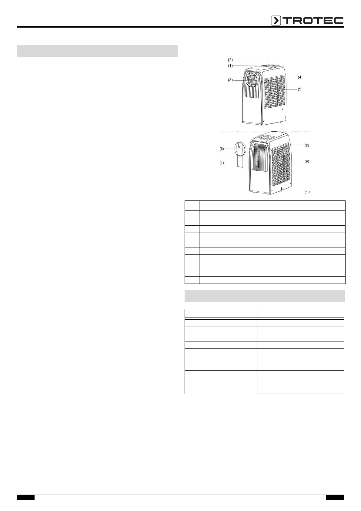
Device depiction
No. Operating element
(1) Control panel
(2) Remote control receiver
(3) Warm air outlet
(4) Evaporator filter
(5) Cooling air inlet
(6) Exhaust air hose connector
(7) Cooling air outlet
(8) Condenser filter
(9) Ambient air inlet
(10) Drain hole
Technical data
Parameter Value
Model PAC 2000 X
Dehumidification performance 30 l per day
Cooling capacity 2000 W
Electric connection 220 V AC, 50 Hz
Nominal cooling capacity 900 W
Refrigerant R410A
Dimensions (WxDxH) 288 mm x 428 mm x 625 mm
Minimum distance
to walls or other objects
Scope of delivery
1 x air conditioner PAC 2000 X
1 x exhaust air hose
1 x remote control
1 x 3 V lithium battery CR002
A: Top: 50 cm
B: Rear: 50 cm
C: Side: 50 cm
D: Front: 50 cm
EN Operating manual – Local air conditioner PAC 2000 X 2
Page 4

Safety
Carefully read the operating manual before using the device and keep it within reach!
• Do not use the device in potentially explosive rooms.
• Do not use the device in atmospheres containing oil, sulphur,
chlorine or salt.
• Set the device up in an upright and stable position.
• Let the device dry out after a wet clean. Do not operate it
when wet.
• Make sure that the air inlet and outlet are not obstructed.
• Make sure that the suction side is kept free of dirt and loose
objects.
• Never insert objects into the device.
• Do not cover or transport the device during operation.
• Ensure that all electric cables outside of the device are
protected from damage (e.g. caused by animals).
• Observe the device's power input, cable length and intended
use when selecting extensions to the connecting cable. Avoid
electrical overload.
• Only transport the device in an upright position with an
emptied condensation tank or condensation drain hose.
• Dispose of the collected condensate. Do not drink it. Health
hazard!
• Do not remove any safety signs, stickers or labels from the
device. Keep all safety signs, stickers and labels in legible
condition.
• Observe the storage and operating conditions (see chapter
Technical data).
Intended use
Only use the device for cooling, ventilating and dehumidifying
room air in closed rooms whilst adhering to and following the
technical data.
Improper use
Do not place the device on damp or flooded ground. Do not use
the device outdoors. Do not place any objects, e.g. wet clothing,
on the device for drying. Any unauthorised changes,
modifications or alterations of the device are forbidden.
Personnel qualifications
People who use this device must:
• be aware of the dangers that occur when working with
electric devices in damp areas.
• have read and understood the operating manual, especially
the Safety chapter.
Residual risks
Hazardous electric voltage!
Work on the electrical components must only be
carried out by an authorised specialist company!
Danger!
Do not leave the packaging lying around. Children may
use it as a dangerous toy.
Danger!
This device can be dangerous if it is used by untrained
people in an unprofessional or improper way. Observe the
personnel qualifications.
Caution!
To avoid damages to the device, never operate the device
without an inserted air filter!
Transport and storage
Transport
To make the device easier to transport, it is fitted with wheels.
Before transporting the device, proceed as follows:
1. Switch off the device.
2. Remove the mains plug from the mains socket. Do not use
the power cable to drag the device!
3. Empty the water tank.
Storage
Empty the condensation tank (see chapter Maintenance).
When the device is not being used, observe the following storage
conditions:
•dry
• protected from dust and direct sunlight
• with a plastic cover to protect it from invasive dust, if
necessary
3 Operating manual – Local air conditioner PAC 2000 X EN
Page 5
Operation
CC
A
B
D
• Avoid open doors and windows.
• Do not exceed the recommended room size.
• Keep curtains and venetian blinds closed during the sunniest
time of the day.
• Keep the filter clean.
• Reduce the temperature and ventilation settings as soon as
the room has reached the desired ambient conditions.
• During cooling operation there is no need for a drain pipe
being installed. Make sure that the rubber cap is positioned
on the drain hole while the device is running.
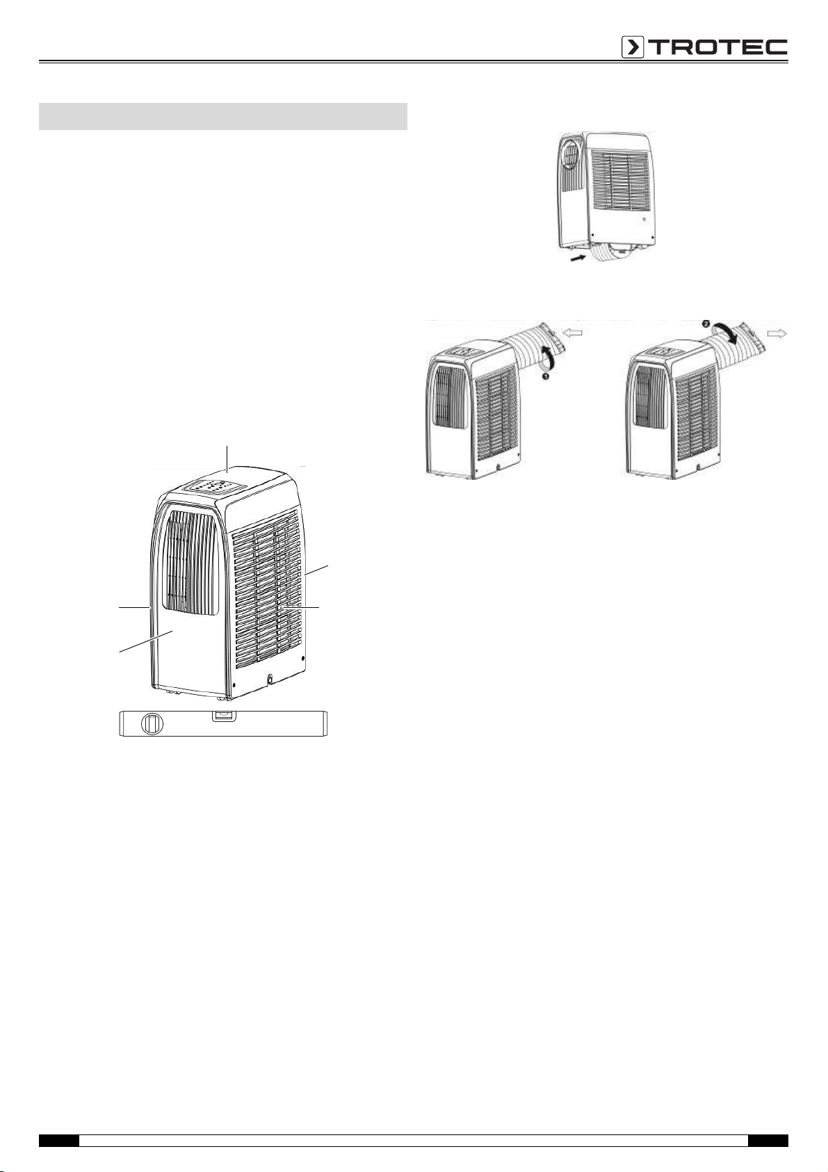
Positioning the device
When positioning the device, observe the minimum distance from
walls or other objects as described in the chapter Technical data.
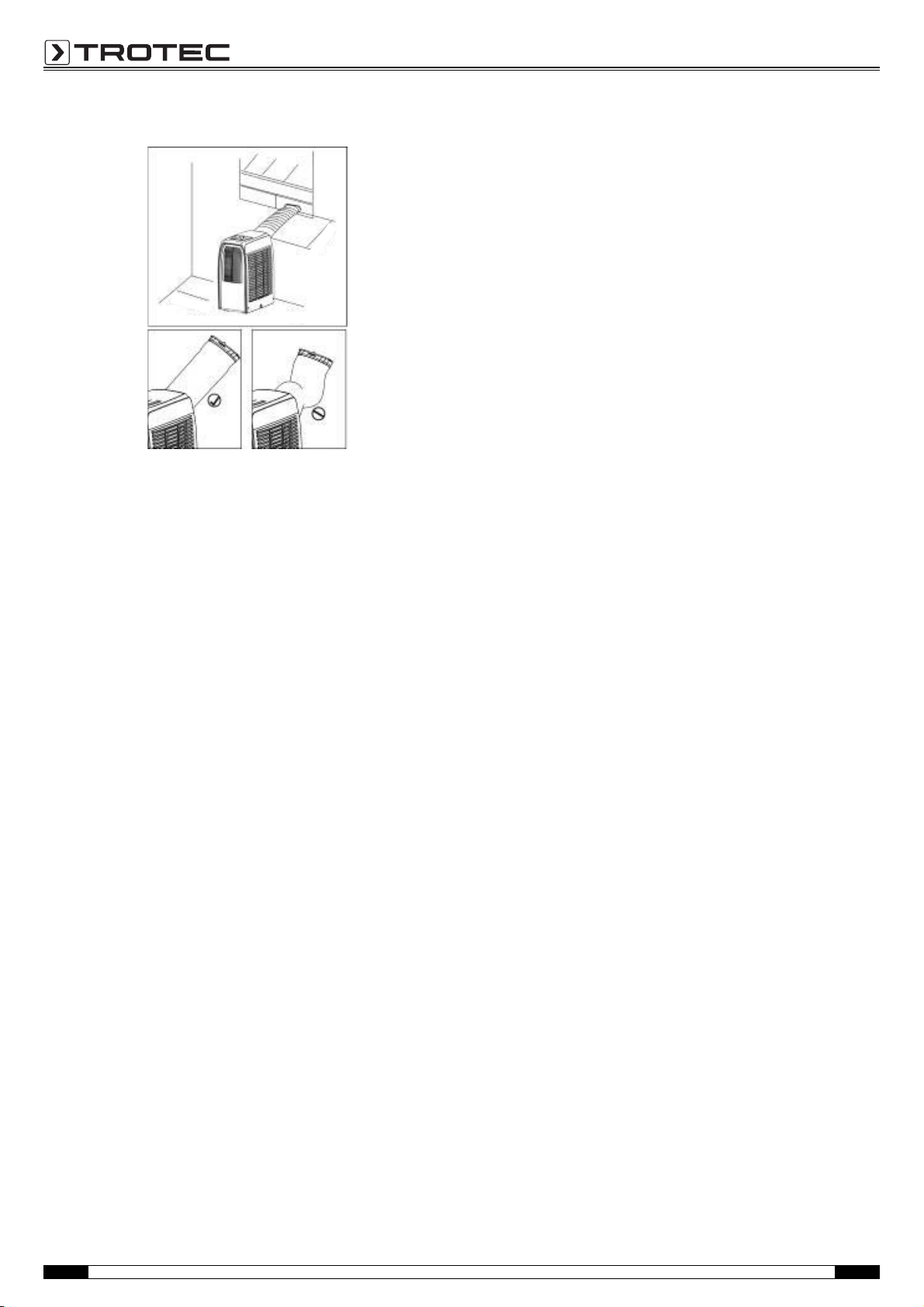
Connecting the exhaust air hose
1. Slightly tilt the device in order to extract the exhaust air hose
from the bottom of the device as depicted.
1. The exhaust air hose can be connected to the device by
turning it in the direction of the arrow.
2. Rotate the exhaust air hose again in the direction of the
arrow, this time to disconnect it.
• Set the device up in a level, upright and stable position.
• Do not create tripping hazards when laying the power cable
or other electric cables.
• Make sure that no curtains or other objects interfere with the
air flow.
EN Operating manual – Local air conditioner PAC 2000 X 4
Page 6
Discharging exhaust air
• The length of the exhaust air hose should not exceed 4 m.
The exhaust air hose must not be bent up or down.
• A minimum distance of 500 mm is to be observed between
the filter side of the device and the wall or other obstacles.
Start-up
• Prior to initial start-up, the battery included in the scope of
delivery must be inserted in the remote control.
– To do so, open the cover of the battery compartment at the
back of the remote control.
– Insert the battery observing the correct polarity. Go by the
marking inside the battery compartment.
– Then close the battery compartment.
• Check air inlets and outlets for foreign objects and remove
these, if necessary.
• Check the air filter for dirt and clean it, if required. Also see
chapter Maintenance.
Switching the device on
1. Insert the mains plug into a properly secured mains socket.
2. Use the power button (1) to switch the device on.
– To prolong the compressor lifetime, wait for at least
3.5 minutes after switch-off before switching the device
back on.
5 Operating manual – Local air conditioner PAC 2000 X EN
Page 7

Control panel
(10)
(11)
(12)
(13)
(17)
(16)
(15)
(14)
No. Designation Function
1 Power Press this button to turn the device on or off.
2 Functions Use this button to set cooling, heating or dehumidification operating mode.
3 Temperature control (+) Pressing this button during cooling operation increases the preset temperature by
4 Temperature control (-) Pressing this button during cooling operation reduces the preset temperature by
5 LED display The display indicates the current temperature or timer settings.
6 SPEED Press this button to adjust the fan speed.
7 PROGRAMMABLE TIMER
8SLEEP
9 Alarm Once the maximum filling level of the water tank is reached, E4 or the ALARM
10 LED speed high high fan speed indicator
11 LED speed medium medium fan speed indicator
12 LED speed low low fan speed indicator
13 LED auto mode AUTO mode indicator
14 LED sleep mode SLEEP mode indicator
15 LED dehumidifying dehumidification operating mode indicator
16 LED heating heating operating mode indicator
17 LED cooling cooling operating mode indicator
1 °C each time it is actuated; the maximum limit is 30 °C.
Pressing this button during heating operation increases the preset temperature
by 1 °C each time it is actuated; the maximum limit is 25 °C.
1 °C each time it is actuated; the minimum limit is 17 °C.
Pressing this button during heating operation reduces the preset temperature by
1 °C each time it is actuated; the minimum limit is 15 °C.
If the set temperature or timer value is to be adjusted, the new setting will be
indicated, then the display returns to the currently set temperature.
The display also serves to indicate error messages in case of a fault, see
ERROR CODES.
During heating and dehumidification operation this button is disabled.
warning light appears on the display.
EN Operating manual – Local air conditioner PAC 2000 X 6
Page 8

Setting the operating mode
• To set the operating mode, press the Functions button (2):
–cooling,
–heating,
– dehumidifying (drying).
Setting the temperature
• Use the temperature control buttons (+ (3) or - (4)) to set the
desired temperature.
Setting the fan speed
• Choose from the available speed levels by pressing the
button Speed (6).
–Low
–Medium
–High
–Auto
Note:
During dehumidification operation this button is disabled, since in
dehumidification mode the device can only be operated at low fan
speed.
If AUTO is selected during cooling operation, the device
automatically switches between the other three speed levels –
depending on the temperature difference between the set and the
actual ambient temperature.
Setting the timer
Timer on
TIMER ON is used to turn the device on automatically after the set
time has passed.
• Press the TIMER button (7) in stand-by to set the desired
time.
• Once the set number of hours has lapsed, the device will
switch on automatically.
• If you press the POWER button (1) before the time has
expired, the device will switch on and the set time will be
deleted.
• You can also determine the function and fan speed while
setting the timer.
Timer off
TIMER OFF is used to turn the device off automatically after the
set time has passed.
• Press the TIMER button (7) during operation to set the desired
time.
• Once the set number of hours has lapsed, the device will
switch off automatically.
• If you press the POWER button (1) before the time has
expired, the device will switch off and the set time will be
deleted.
Sleep control function
Note:
The sleep control function is only available in cooling mode.
• Press the SLEEP button (8) during cooling operation to set the
temperature. After one hour the temperature increases by
1 °C and maximally by 2 °C after 2 hours.
• Actuating the SLEEP button (8) again deactivates this setting.
Dehumidification operation (drying)
• The temperature cannot be regulated during
dehumidification operation, the fan speed is low.
• In dehumidification (drying) mode humidity is extracted from
the air and collected in an internal tank.
• Once the maximum filling level of the water tank is reached,
E4 or the ALARM warning light appears on the display.
• Drain the water tank when it is full. See Emptying the
condensation tank on page 11.
Discharging the condensate
• In dehumidification mode the rubber cap on the drain hole (1)
is to be removed and replaced by a proper drain pipe.
• Remove the exhaust air hose, connect a drain pipe to the
drain hole (1) and drain the water to enhance the
dehumidification capacity.
7 Operating manual – Local air conditioner PAC 2000 X EN
Page 9

Heating
(6)
(7)
1.
9.
8.
2.
7.
6.
5.
4.
3.
9.
• If you want to utilize the heating function, the following
modification is required:
1. Detach the exhaust air hose.
2. Mount the connection piece for the exhaust air hose (6) to the
cooling air outlet (7).
Remote control
All settings of the device can also be made using the remote
control included in the scope of delivery. Please gather the button
functions from the Control panel paragraph.
No. Operating element Function
1. Power Power button
2. Func Operating mode selector
3. Timer Timer switch
4. Auto Automatic fan speed
5. Hi High fan speed
6. Mid Medium fan speed
7. Low Low fan speed
8. Sleep Sleep control function
9. Tem p Temperat ur e c o n t r o l
3. Fit the exhaust air hose to the connection piece (6).
4. Align the pivotable nozzle.
Start heating function
• Press the functions button (2) until the LED for heating (16)
lights up.
– The device will start after a few seconds.
Note:
Heating is possible up to a max. ambient temperature of 25 °C.
At an ambient temperature of more than 25 °C the heating
function will not start.
Shutdown
1. Use the power button (A) to switch the device off.
2. Remove the mains plug from the mains socket.
3. Clean the device, and especially the air filter, according to
chapter Maintenance.
4. Store the device according to the Storage chapter.
Errors and faults
The device has been checked for proper functioning several times
during production. If malfunctions occur nonetheless, check the
device according to the following list.
Display indication
E1 Short circuit on both
E2 Short circuit on
ALARM / E4 Indicates full water tank or
Your device still does not operate correctly after these checks?
Bring the device to a specialist company for cooling and
air-conditioning or to Trotec for repair.
Cause Troubleshooting
temperature sensor and
PCB.
temperature sensor copper
tube and PCB wiring.
poor contact of the signal
plug.
Contact an electrician for
repair.
Contact an electrician for
repair.
Drain water.
See Emptying the
condensation tank on
page 11.
EN Operating manual – Local air conditioner PAC 2000 X 8
Page 10

Maintenance
Maintenance intervals
Maintenance and care interval
Empty the condensation tank x
Check the air inlets and outlets for dirt and
foreign objects and clean if necessary
Clean the exterior xx
Visually check the inside of the device for dirt xx
Check the air inlet grid and air filter for dirt
and foreign objects and clean or replace if
necessary
Replace the air filter x
Check for damage x
Check the attachment screws xx
Tes t ru n x
before every
start-up
x
xx
as needed
at least every
2weeks
at least every
4weeks
at least every
6 months
at least
annually
Maintenance and care log
Device type: ............................ Device number: .......................................
Maintenance and care interval 12345678910111213141516
Check air inlets and outlets for dirt and foreign
objects and clean if necessary
Clean the exterior
Visually check the inside of the device for dirt
Check the air inlet grid and air filter for dirt and
foreign objects and clean or replace if necessary
Replace the air filter
Check for damage
Check the attachment screws
Tes t ru n
1. Date: ..........................................
Signature:.......................................
5. Date: ..........................................
Signature:.......................................
9. Date: ..........................................
Signature:.......................................
13. Date: ........................................
Signature:.......................................
2. Date:..........................................
Signature: ......................................
6. Date:..........................................
Signature: ......................................
10. Date:........................................
Signature: ......................................
14. Date:........................................
Signature: ......................................
3. Date: ..........................................
Signature:.......................................
7. Date: ..........................................
Signature:.......................................
11. Date: ........................................
Signature:.......................................
15. Date: ........................................
Signature:.......................................
4. Date: ..........................................
Signature: ......................................
8. Date: ..........................................
Signature: ......................................
12. Date: ........................................
Signature: ......................................
16. Date: ........................................
Signature: ......................................
9 Operating manual – Local air conditioner PAC 2000 X EN
Page 11

Activities required before starting maintenance
• Do not touch the mains plug with wet or damp hands.
• Before any work, remove the mains plug!
Maintenance tasks which require the housing to be opened must only be carried out by specialist companies for cooling and air-conditioning or by Trotec.
Visual checks for dirt inside the device
1. Remove the air filter.
2. Use a torch to illuminate the openings of the device.
3. If you see a thick layer of dust, have the inside of the device
cleaned by a specialist company for cooling and
air-conditioning or by Trotec.
4. Put the air filter back in.
Cleaning the housing
Clean the device with a soft, damp and lint-free cloth. Ensure that
no moisture enters the housing. Do not use any sprays, solvents,
alcohol-based cleaning agents or abrasive cleaners. Only use
clean water to moisten the cloth.
Refrigerant circuit
• The entire refrigerant circuit is a maintenance-free,
hermetically sealed system and may only be maintained or
repaired by specialist companies for cooling and
air-conditioning or by Trotec.
Condenser/evaporator
• Use a vacuum cleaner with brush attachment.
EN Operating manual – Local air conditioner PAC 2000 X 10
Page 12

Emptying the condensation tank
A.
B.
1. First remove the rubber cap from the drain hole to drain the
water.
2. After draining is completed, restart the device, then the unit
can operate normally.
Cleaning the air inlets and the air filter
Caution!
Ensure that the air filter is not worn or damaged. The
corners and edges of the air filter must not be deformed
or rounded. Before reinserting the air filter, make sure
that it is undamaged and dry!
Read the chapter Maintenance intervals and replace the
air filter in due time!
11 Operating manual – Local air conditioner PAC 2000 X EN
Page 13

Disposal
The icon with the crossed-out waste bin on waste
electrical or electronic equipment stipulates that this
equipment must not be disposed of with the household
waste at the end of its life. You will find collection
points for free return of waste electrical and electronic equipment
in your vicinity. The addresses can be obtained from your
municipality or local administration. For further return options
provided by us please refer to our website www.trotec24.com.
The separate collection of waste electrical and electronic
equipment aims to enable the re-use, recycling and other forms
of recovery of waste equipment as well as to prevent negative
effects for the environment and human health caused by the
disposal of hazardous substances potentially contained in the
equipment.
You are responsible for deleting any personal data stored on the
waste equipment to be disposed of.
The device is operated with fluorinated greenhouse gas, which
can be dangerous for the environment and contribute to global
warming when emitted to the atmosphere.
Further information is provided on the nameplate.
Dispose of the refrigerant appropriately and according to the
national regulations.
EN Operating manual – Local air conditioner PAC 2000 X 12
Page 14

Produktdatenblatt / Product Fiche
Lokales Klimagerät / Local Air Conditioner
PAC 2000 X
Artikel-Nr. / Item-No.
1.210.002.003
L
WA
dB(A) re 1 pW
Typ / Type
Gewicht / Weight
g
GWP
- CO₂-Äquivalent / CO₂-Equivalent
t CO2 äq.
0,94
DE
Der Austritt von Kältemittel trägt zum Klimawandel bei.
Kältemittel mit geringerem Treibhauspotenzial tragen im Fall eines Austretens weniger zur Erderwärmung bei als solche mit höherem Treibhauspotenzial.
Dieses Gerät enthält Kältemittel mit einem Treibhauspotenzial von GWP = 2088. Ein Austreten von 1 kg dieses Kältemittels hätte eine um diesen Faktor
größere Auswirkung auf die Erderwärmung als 1 kg CO² bezogen auf hundert Jahre.
Nehmen Sie keine Arbeiten am Kältekreislauf vor, zerlegen Sie das Gerät nicht.
Ziehen Sie bei Arbeiten am Gerät stets Fachpersonal hinzu und lassen Sie das im Gerät befindliche Kältemittel sachgerecht entsprechend der nationalen
Gesetzgebung entsorgen.
EN
Refrigerant leakage contributes to climate change.
Refrigerant with lower global warming potential (GWP) would contribute less to global warming than a refrigerant with higher GWP, if leaked to the atmosphere.
atmosphere, the impact on global warming would be by this GWP-factor higher than 1 kg of CO2, over a period of 100 years.
Never try to interfere with the refrigerant circuit yourself or disassemble the product yourself and always ask a professional.
At the end of its life please dispose of the refrigerant appropriately to the relevant legal requirements and national regulations.
Nenn-Leistungszahl im Kühlbetrieb / Rated EER
EER
rated 2,6
Nenn-Leistungszahl im Heizbetrieb / Rated COP
COP
rated 3,1
Energieeffizienzklasse im Kühlbetrieb/ Energy Efficiency Class Cooling Mode
A
Energieeffizienzklasse im Heizbetrieb/ Energy Efficiency Class Heating Mode
A++
Indikativer Stromverbrauch pro Stunde im Kühlbetrieb/ Electricity Consumption Cooling Mode
²Q
SD
kWh / 60 min
0,8
Indikativer Stromverbrauch pro Stunde im Heizbetrieb/ Electricity Consumption Heating Mode
²Q
SD
kWh / 60 min
0,6
Nennleistung im Kühlbetrieb / Nom. Power Cooling Mode
P
rated
kW
2,0
Nennleistung im Heizbetrieb / Nom. Power Heating Mode
P
rated
kW
2,0
Nenn-Leistungsaufnahme im Kühlbetrieb / Nom. Power Consumption Cooling Mode
P
EER
kW
0,9
Nenn-Leistungsaufnahme im Heizbetrieb / Nom. Power Consumption Heating Mode
P
COP
kW
0,7
Leistungsaufnahme im AUS-Zustand / Power OFF Mode
P
OFF
W
-
P
SB
W
0,4
Leistungsaufnahme mit Temperaturregler AUS / Thermostat OFF Mode
P
TO
W
95,9
²Energieverbrauch im Kühlbetrieb 0,8 kWh je 60 min auf der Grundlage von Ergebnissen der Normprüfung. Der tatsächliche Verbrauch hängt von der Nutzung und vom Standort des Geräts ab.
²Energieverbrauch im Heizbetrieb 0,6 kWh je 60 min auf der Grundlage von Ergebnissen der Normprüfung. Der tatsächliche Verbrauch hängt von der Nutzung und vom Standort des Geräts ab.
PRODUKTFOTO
R-410A
450
This appliance contains a refrigerant fluid with a GWP-factor equal to 2088. This means that if 1 kg of this refrigerant fluid would be leaked to the
Energy consumption Cooling Mode 0,8 kWh / 60 minutes, based on standard test results. Actual energy consumption will depend on how the appliance is used and where it is located.
- Treibhauspotenzial / Global Warming Potential
2.088
Schallleistungspegel / Sound Power Level
Kältemittel / Refrigerant
Funktion
nur Kühlung / Cooling only
65
Leistungsaufnahme im Bereitschaftszustand /
Stand-By Power Consumption
Energy consumption Heating Mode 0,6 kWh / 60 minutes, based on standard test results. Actual energy consumption will depend on how the appliance is used and where it is located.
Page 15

Entfeuchtungsleistung / Dehumidifying Volume
l/h
Betriebstemperatur / Operating Temperature
°C
Einstellbereich Temperatur im Kühlbetrieb/ Set Temperature Range Cooling Mode
°C
Einstellbereich Temperatur im Heizbetrieb/ Set Temperature Range Heating Mode
°C 15-25
max. Luftvolumenstrom / max. Air Flow Volume
m3/h
Netzanschluss / Power connection
Nennstrom / Nom. Current
A
Schalldruckpegel / Sound Pressure Level
dB(A)
Gewicht / Weight
kg
Abmessungen / Dimensions
BxHxT / WxHxD
mm
cm
Mindestabstand zu Wänden + Gegenständen /
Minimum distance to walls and objects
428x625x288
50
360
1/N/PE~ 220-240 V 50 Hz
3,95026,5
17-30
5-35
1,25
Page 16

Page 17

Page 18

Trotec GmbH & Co. KG
Grebbener Str. 7
D-52525 Heinsberg
+49 2452 962-400
+49 2452 962-200
info@trotec.com
www.trotec.com
 Loading...