

Page 1

LV / V - Serie
Operating manual – Infrared camera B - 1
TRO-TR-BA-LV/V-SERIE-01-10-GB
TROTEC® GmbH & Co. KG • Grebbener Straße 7 • D-52525 Heinsberg
Tel.: +49 (0) 24 52 / 962 - 400 • Fax: +49 (0) 24 52 / 962 - 200
www.trotec.de • E-Mail: info@trotec.de
Page 2

B - 1
Operating manual – Infrared camera
OVERVIEW OF CONTENTS
01. Read This First . . . . . . . . . . . . . . . . . B - 02
02. Component Guide . . . . . . . . . . . . . . . B - 04
Front View . . . . . . . . . . . . . . . . . . . . B - 04
Back/ Bottom View . . . . . . . . . . . . . . . B - 04
Keys/ Dock . . . . . . . . . . . . . . . . . . . . B - 04
03. Preparing the IR Camera . . . . . . . . . . B - 05
Charging the Battery Pack . . . . . . . . . . B - 05
Installing the Battery Pack / SD Card . . . B - 05
Turning the Power On/ Off . . . . . . . . . . B - 06
Checking the Information . . . . . . . . . . . B - 06
Setting the Date/ Time . . . . . . . . . . . . . B - 07
Local Settings . . . . . . . . . . . . . . . . . . B - 07
04. Basic Functions . . . . . . . . . . . . . . . . B - 08
Using the LCD Monitor . . . . . . . . . . . . . B - 08
Selecting Menus and Settings . . . . . . . . B - 08
Resetting the settings to Default . . . . . . . B - 09
05. Shooting . . . . . . . . . . . . . . . . . . . . . B - 09
Focus . . . . . . . . . . . . . . . . . . . . . . . . B - 09
Thermal and Visual Images Display . . . . B - 09
DuoVision . . . . . . . . . . . . . . . . . . . . . B - 10
Image Only . . . . . . . . . . . . . . . . . . . . B - 10
Image Adjustment . . . . . . . . . . . . . . . . B - 10
Auto Adjust . . . . . . . . . . . . . . . . . . . . B - 10
Manual Adjustment . . . . . . . . . . . . . . . B - 11
Image Settings . . . . . . . . . . . . . . . . . . B - 11
Measurement Range . . . . . . . . . . . . . . B - 12
Freezing/ Activating an Image . . . . . . . . B - 12
Setting Analysis Parameters . . . . . . . . . B - 12
Analysis Settings . . . . . . . . . . . . . . . . B - 13
Spot Analysis . . . . . . . . . . . . . . . . . . . B - 14
Isothermal Analysis . . . . . . . . . . . . . . . B - 14
Remove Analysis Tools . . . . . . . . . . . . . B - 14
Saving Image . . . . . . . . . . . . . . . . . . B - 15
Attaching Memos to Images . . . . . . . . . B - 15
Trigger Setting . . . . . . . . . . . . . . . . . . B - 15
Trigger informations . . . . . . . . . . . . . . B - 15
06. Playback and Delte . . . . . . . . . . . . . B - 15
Opening Images . . . . . . . . . . . . . . . . . B - 15
Playback Memos . . . . . . . . . . . . . . . . B - 15
Deleting Images . . . . . . . . . . . . . . . . . . . B - 16
07. Download the Images . . . . . . . . . . . B - 17
Download via SD Card . . . . . . . . . . . . . B - 17
08. Connecting and Download . . . . . . . . . . B - 18
Charging via the Dock . . . . . . . . . . . . . B - 18
Connecting to a Monitor . . . . . . . . . . . . B - 18
Connecting to a Computer . . . . . . . . . . B - 18
Installing Drivers . . . . . . . . . . . . . . . . B - 19
Transfer Video via USB . . . . . . . . . . . . B - 19
- Trouble Shooting . . . . . . . . . . . . . . . B - 19
- Use the Bluetooth Headset . . . . . . . . . B - 19
09. Care and Maintenance . . . . . . . . . . . B - 19
10. Trouble Shooting . . . . . . . . . . . . . . B - 21
11. Emissivity table . . . . . . . . . . . . . . . . B - 22
12. Specifications . . . . . . . . . . . . . . . . . B - 24
This publication replaces all previous announcements. No part of this publication
may be reproduced, processed using electronic systems, replicated or distributed
in any form, without our written authorisation. Subject to technical changes. All
rights reserved. Names of goods are used without guarantee of free usage keeping to the manufacturer‘s syntax. The names of goods used are registered and
should be considered as such. We reserve the right to modify design in the interest of ongoing product improvement, such as sha pe and colour modifications.
The scope of delivery may vary from that in the product description. All due care
has been taken in compiling this document. We accept no liability for errors or
omissions. © TROTEC
®
Page 3

Operating manual – Infrared camera
B - 2
01. READ THIS FIRST
Test Shots
Before you try to shoot important subjects, we highly recommend that you shoot several trial images to
ensure that the IR camera is operating and being operated correctly.
Please note that Trotec, its subsidiaries and affiliates,
and its distributors are not liable for any consequential damages arising from any malfunction of an IR
camera or accessory that results in the failure of an
image to be recorded or to be recorded in a format
that is machine-readable.
Warning Against Copyright Infringement!
Safety Precautions
Before using the camera, please ensure that you read
and understand the safety precautions described
below. Always ensure that the IR camera is operated
correctly.
The safety precautions noted on the following pages
are intended to instruct you in the safe and correct
operation of the IR camera and its accessories to prevent injuries or damage to yourself, other persons and
equipment.
Warnings
Read on to learn about using IR camera properly.
- Avoid damaging eyesight.
Do not trigger the laser pointer in human or
animal eyes. Exposure to the laser produced by
the laser pointer may damage eyesight.
- Do not disassemble.
Do not attempt to disassemble or alter any part of
the equipment that is not expressly described in this
guide.
- Stop operating immediately in case of smoke or
noxious fumes.
Failure to do so may result in fire or electrical shock.
Immediately turn the IR camera’s power off, remove
the IR camera battery or unplug the power cord from
the power outlet. Ensure that smoke and fume
emissions have ceased.
- Stop operating immediately if it is dropped or the
casing is damaged.
Failure to do so may result in fire or electrical
shock. Immediately turn the IR camera’s power off,
remove the IR camera battery or unplug the power
cord from the power outlet.
- Do not use substances containing alcohol, benzene,
thinners or other flammable substances to clean
the IR camera.
The use of these substances may lead to fire.
- Remove the power cord on a regular periodic basis and
wipe away the dust and dirt that collects on the plug, the
exterior of the power outlet and the surrounding area.
In dust, humid or greasy environments, the dust that
collects around the plug over long periods of time
may become saturated with humidity and produce/
cause short-circuits, leading to fire.
- Do not handle the power cord if your hands are wet.
Handling it with wet hands may lead to electrical
shock. When unplugging the cord, ensure that you
hold the solid portion of the plug. Pulling on the fle xible portion of the cord may damage or expose the
wire and insulation, creating the potential for fires
and electrical shocks.
- Do not cut, alter or place heavy items on the power
adapter cord.
Any of these actions may cause an electrical short
circuit, which may lead to fire or electrical shock.
- Use only the recommended power accessories.
Use of power sources not expressly recommended for
this IR camera may lead to overheating, distortion of
the IR camera, fire, electrical shock or other hazards.
Page 4

B - 3
Operating manual – Infrared camera
- Do not place the batteries near a heat source or ex pose them to direct flame or heat.
Neither should you immerse them in water. Such
exposure may damage the batteries and lead to the
leakage of corrosive liquids, fire, electrical shock,
explosion or serious injury.
- Do not attempt to disassemble, alter or apply heat to
the batteries.
There is a serious risk of injury due to explosion.
Immediately flush with water any area of the body,
including the eyes and mouth, or clothing, that comes
into contact with the inner contents of a battery.
In case of contact of the eyes or mouth with these
substances, immediately flush with water and seek
medical assistance.
- Avoid dropping or subjecting the batteries to severe
impacts that could damage the casings.
It could lead to leakage and injury.
- Do not short-circuit the battery terminals with metallic
objects, such as key holders. It could lead to overheat-
ing, burns and other injuries.
- Before you discard a battery, cover the terminal with
tape or other insulators to prevent direct contact
with other objects.
Contact with the metallic components of other materials
in waste containers may lead to fire or explosions. Dis card the batteries in specialized waste facilities if
available in your area.
- Use only recommended batteries and accessories.
Use of batteries not expressly recommended for this
equipment may cause explosions or leaks, resulting
in fire, injury and damage to the surroundings.
- Disconnect the compact power adapter from both
the IR camera and power outlet after recharging
and when the IR camera is not in use to avoid fires
and other hazards. Continuous use over a long period
of time may cause the unit to overheat and distort,
resulting in fire.
- Do not use the battery charger or compact power
adapter if the cable or plug is damaged, or if the plug
is not fully inserted into the power outlet.
The battery charger varies according to your region.
- Exercise due caution when screwing on the separately
sold tele-lens, close-up lens.
If you loosen, fall off and shatter, the glass shards
may cause an injury.
- If your camera is used for an extended period, the IR
camera body may become warm.
Please take care when operating the IR camera for an
extended period as your hands may experience a bur ning sensation.
Prevent Malfunction
Read on to learn about preventing malfunction of IR
camera.
- Avoid damaging the detector of the IR camera
- Avoid condensation related problems
Moving the IR camera rapidly between hot and cold
temperatures may cause condensation (water drop lets) to form on its external and internal surfaces.
You can avoid this by placing the IR camera in the
plastic case (bundle) and letting it adjust to tempe rature changes slowly before removing it from the
case.
- If condensation forms inside the IR camera.
Stop using the camera immediately if you detect conden sation. Continued use may damage the IR camera.
Remove the PC card, and battery or a household power
source, from the IR camera and wait until moisture
evaporates completely before resuming use.
- Extended storage
When not using the IR camera for extended periods of
time, remove the battery from the IR camera or battery
charger and store the IR camera in a safe place. Storing
the IR camera for extended periods with battery in
place will run down the battery.
Page 5

Operating manual – Infrared camera
B - 4
02. COMPONENT GUIDE
Front
Illuminator
Visual lens
IR lens
Laser Pointer
Definable trigger
Back view
Power indicator
Cancel
LCD display
Key pad
Lens locker
Battery pack cover
Controls / multifunction-dock port
Battery cover locker
Video output
miniSD card
Power supply
USB 2.0
(optional)
Auto adjust
Menu/Enter
Freeze/Saving
Power Switch
Page 6

B - 5
Operating manual – Infrared camera
03. PREPARING THE IR CAMERA
Charging the Battery Pack
For the following procedures to charge the battery
pack for the first time and subsequently when the low
battery icon appears on the Display Panel.
1. Align the edge of the
battery pack with the
line on the battery,
then insert the battery
in the direction of the
arrow.
Installing the Battery Pack / SD Card
Install Battery Pack into the camera as follows:
1. Check that the power is off
and slide the battery cover
in the direction of the arrow.
2. Insert the battery in the
direction of the arrow.
2. Attach the power cord to the battery charger
and plug the other end into a power outlet.
• The charge indicator lights red while the battery
pack is charging and lights green when charging is
complete.
• After charging, unplug the battery charger and
remove the battery pack.
• ThebatteryisanLi-Ionbattery.Therefore,itcanbe
recharges before being completely discharged.
This is a lithium ion battery pack so there is no need
to complete use or discharge it before recharging. It
can be recharged at any time. However, since the
maximum number of charge cycles is approximately
300 (battery life), it is recommended to recharge the
battery pack only after having discharged it completely
to extend battery life.
Charging times will vary according to the surrounding
humidity and battery pack charge state.
3. Insert the SD card in the
direction of the arrow.
Remove the battery pack when the camera
is not in use.
The SD Card must be formatted in FAT16 or
FAT32. Otherwise, the IR camera may not recog nize the memory.
Battery Status Symbols
The following icons indicate the battery status on the
LCD display.
Sufficient battery change
Low battery
Replace or recharge battery
Page 7

Operating manual – Infrared camera
B - 6
Turning the Power On / Off
The power indicator remains lit while the power of the
camera is on.
1. Holding the camera cor rectly with your right hand,
put your thumb above the
key pad and put your fore fi nger in front of the defi nable trigger.
2. Press and hold the power
switch for 3 seconds. The
power indicator lights green.
3. After a while, a startup
image will appear on the
screen.
4. To turn off, hold the Power Hold the power switch
for 3 seconds. The power indicator goes off.
Checking the Information on the LCD Monitor
The LCD monitor has a fi eld of vision of 100% of the
actual shooting image.
The display shows the Info view.
About the operation indicator
The operation indicator shows the status of the camera.
Menu . . . . . . . . . . . . . . . . . . Represents the menu mode.
Null . . . . . . . . . . . . . . . . . . Represents the non-menu mode
no analysis tools selected.
1 - 4 . . . . . . . . . . . . . . Represents the current analysis tool
(sport 1 or spot 2 or spot 3).
Cap . . . . . . . . . . . . . . . . . . . . Reprents the current analysis
tool (auto-tracking spot).
Isot . . . . . . . . . . . . . . . . Represents the current analysis
tool (isothermnalysis).
E . . . . . . . . . . . . . . . . . . . . . . . . . . . . . . Current emissivity.
. . . . . . . . . . . . . . . . . . . . . SD card has been inserted.
. . . . . . . . . . . . Bluetooth headset has been installed.
Before starting up the camera, please enter [Null]
mode. Press the cancel key repeatedly until you
see the message „null“ in the operation indicator.
Reading
Status of the camera
Live/
Freeze
Operation indicator
Current Emissivity
Battery Status
Time
Upper limit of
color scale
Lower limit of
color scale
Color scale
NULL E
1.00
Page 8

B - 7
Operating manual – Infrared camera
Setting the date and time
You need to set Data / Time when the IR camera is turned
on for the first time.
1. Check that the IR camera is in null mode.
2. Press the MENU/ENTER
key, then press the
3
Up or Down ar-
3
row on the omni se lector to select the
[Setup] menu.
3. Press the Up or
Do wn arrow on the
3
3
omni selector to select
[Date & Time], then press the MENU/ENTER key.
4. Setting Date and time.
• Press the Up or
Down arrow on
3
3
the omni selector to
select a new field.
• Press the3Left or
Right 4 arrow on the
omni selector to set
the values.
5. After adjusting the settings, press the Menu / Enter
key to close menu window, or press the C key to
exit without saving.
Local Settings
In this menu item, you can display further settings of the
built-in menu system.
3. Press the Up or Down
3
arrow on the omni
3
selector to select [Local], then press the
MENU / ENTER key.
4. Local settings.
• Press the Up or
Down arrow on
3
3
the omni se lector to select
a new field.
•Pressthe3 Left or
Right 4 arrow on
the omni selector to
set the values.
5. After adjusting the settings, press the Menu / Enter
key to close menu window, or press the C key to
exit without saving.
About the local settings
Language . . . . . Selects the language used in the menus
and messages.
IR/Vision . . . . . . . . . . . . . . . . Selects the displayed mode.
Temp unit . . . . . . . . . . . Sets the format of the displayed
temperature unit of the camera. °C or °F.
Distance unit . . . . . . . . . . Sets the format of the displayed
distance unit of the camera. Meter or
Foot.
Video output . . . . Sets the format of the video output of
the camera. PAL or NTSC.
1. Check that the IR camera is in null mode.
2. Press the MENU/ENTER
key, then press the
3
Up or Down ar-
3
row on the omni
selector to select
the [Setup] menu.
Page 9

Operating manual – Infrared camera
B - 8
04. BASIC FUNCTIONS
Using the LCD Monitor
If you wish to use the LCD monitor for shooting, playing back thermal images and adjusting menu settings,
follow the instruction below.
1. Open the LCD dis play in the di rection of the ar r ow.
2 . Aim the IR camera
at a subject.
•Forabettertem-
peratur measu rement, please
do make the
subject in cen ter of the image
that is shown on
the LCD monitor.
•TheLCDwillshutoffwhenclosed.
Selecting Menus and Settings
You can select the settings by pressing the MENU/KEY key.
1.
Press the MENU / ENTER
key.
(1).
2. Press the 3Left, Right
4 or
3
Up, Down
3
1
arrow (2) on the omni
selector.
3. Press the MENU/
2
ENTER button (1).
Example
1. Press the MENU/
ENTER key.
Analysis Menu
File Menu
File Menu
Setup Menu
4. Confirm settings the
Menu/Enter Key.
Displayed menu items will vary according to
the operation and setting contents!
2. Select a function item
using.
Page 10

B - 9
Operating manual – Infrared camera
Resetting the Settings to Default
You can reset the menu and button operation settings
to default.
1. Turn off the IR camera.
on / off
2. Press and hold the Power
switch and C key for some
seconds until the camera
is switched on.
Cancel
The data in storage will not be deleted when you
reset the menu and button operation settings to
default.
05. SHOOTING
Manual Focus
1. Check that the IR camera is in null mode.
2. Aim the IR camera
at the subject.
3. Turn the focus ring to
focus on the target.
4. Do not stop turning
until the image is
clear.
Thermal, Visual and Duovision image display
This IR camera records visual images with its built-in
digital camera. You can capture a visual image as a reference as the thermal image.
1. Press the MENU/EN TER key.
2. Press the Up or
Down
3
arrow on the
3
omni selector to select
the [Setup] menu.
3
3. Press
arrow on the omni
3
Up and Down
selector to select [Lo cal], then
press MENU /
ENTER key.
•A submenu will ap-
pear
on the LCD mo-
nitor.
Page 11

Operating manual – Infrared camera
B - 10
3
4. Press
and Down a rrow on
3
Up
the omni selector to
select [IR/Vision],
and press 3 Left and
Right 4 to select a
display mode, then
press the MENU / ENTER key.
• IR............................DisplaysIRimage.
Vision . . . . . . . . . . . . . . . . . . . . . . Displays visual image.
DuoVision . . . . . . Displays IR image and visual image
together as overlapping images.
DuoVision
The DuoVision display modes allow thermal and visible images to be displayed as overlapping images.
IR
In this mode, you can use
the analysis tools to analyze the target. But what
you see is the image
with some pseudo colors.
Vision
In this mode, you can
see the image with full
colors. But you can not
use any analysis tools to
analyze the target.
DuoVision
The IR image and the
real image are displayed
as overlapping images in
this mode. At the same
time you can use any
analysis tools to analyze
the target.
When the CCD offsets the IR image, hold the C key, and
then press the directional keys to have the CCD superposed on the IR image.
WARNING: This setting depends on the distance
and only possible in the scope of certain opera tions for technical reasons.
Image only
In this mode, analysis
tools and temperature
data do not appear.
1. Press the MENU / EN TER key.
2. Press the
Down arrow on the
3
3
Up or
omni selector to select
the [Image only]
menu.
•Nokindofinfo
appears.
3. Press any key except the power switch key to
cancel the image-only mode.
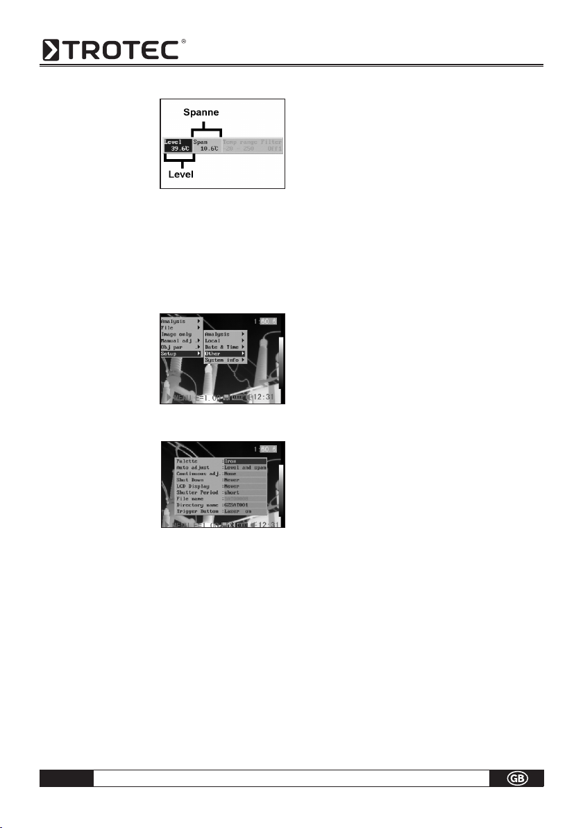
Image adjustment
You can adjust the Level (brightness) and Span (contrast) of the image captured by the IR camera manually
or automatically.
Auto adjust
The IR camera will automatically adjust the brightness
and / or contrast when you press the A key.
Manual adjust
You can adjust the Level and Span of the image manually in the built-in menu system or by pressing arrows
on the omni selector. Press
3
Up and Down arrow
3
to change the span, and press 3Left and Right4 ar-
row to change the level.
1. Press the MENU/EN TER key.
2. Press the Up or
Down arrow on the
3
3
omni selector to select
the [Manual Adjust]
menu.
Page 12
B - 11
Operating manual – Infrared camera
3. Setting Level and
Span.
•Pressthe 3 Left or
Right 4
arrow on the
omni selector to
select a new field.
•Pressthe UporDown arrow on theomni
3
3
selector to set the values.
4. After this operation, press the MENU / ENTER key to
save changes, or press the C key to close the menu
window without saving.
Image Settings
1. Press the MENU / EN TER key.
2. Press 3Left or Right 4
arrow on the omni se lector to select the
[Setup] menu, then
Press the MENU /
ENTER key.
3. Press the Up or
Down
3
arrow on the
3
omni selector to select
[Other], then press the
MENU / ENTER key.
4. Set the Image Settings.
•Pressthe
3
Up or Down arrow on the omni
3
selector to select a new field.
•Press the 3 Left or
Right 4
arrow on the omni
selector to set the values.
5. After this operation, press the MENU / ENTER key to
save changes, or press the C key to close the menu
window without saving.
About the Image Settings:
•Palette
Sets the pseudo colors of the thermal image. The camera provides 6 palettes: Iron, Iron inverted, Rainbow,
Feather, Grey and Grey inverted.
•Auto adjust
Sets the function of the A key. There are three options:
Level and Span, Level, Span.
- Level und Span
The camera will automatically adjust the level (bright ness) and span (contrast) of the image to the optimum
setting.
- Level
The camera will automatically adjust the level
(brightness) of the image.
- Span
The camera will automatically adjust the span
(contrast) of the image.
•Continuous adj
Sets whether the brightness and contrast of the
image shown on screen are adjusted automatically.
- Level and span
The brightness and contrast are adjusted automati cally.
- Level
The camera will automatically adjust the level
(brightness) of the image.
- None
The brightness and contrast will not be adjusted auto matically.
•Automatic shut-down function
The camera turns itself off automatically after a fixed
period.
•LCD display
The LCD display switches to sleep mode after a fixe
period.
The camera itself remains switched on.
•Shutter Speed
The shutter closes in prescribed intervals (short =
approx..each minute / long = approx. every 3 minutes)
• File Name
automatically in ascending order.
Page 13

Operating manual – Infrared camera
B - 12
•Directory Name
The directory name can be increased from GZSAT
001 -250. This means, for example, that each indivi-
dual object can be assigned a special directory.
WARNING: Do not at any time change the name
of the directory to a directory other than one
of those mentioned above! This could lead to
the memory card not being able to recognize
the directory!
•Trigger Button
Different functions can be allocated to the trigger
button on the grip.
Measurement range
The brightness can be decreased by setting the filter
(filter lens for measurements >1000 °C) on or an optional filter using.
1. Press the MENU/ENTER key.
2. Press
3
Up and Down
arrow on the omni
3
selector to select [Ma nual adj.], then press
MENU/ENTER key.
3. Setting measurement
range.
•Press the 3
Left or
Right 4
ar row on the omni se lector to select a
range.
•Press the Up or
Down
3
arrow on the
3
omni select or to set measurement range.
•This option is unavailable when the image
is frozen.
4. After this operation, press the Menu/Enter key to
close the menu window.
Freezing / Activating an image
You can activate / freeze a thermal image by pressing the S key on the selector.
1. Check that the IR camera is in null mode.
2. Press the S key, to
freeze the image.
3. Press the S key
again, then the im age is active.
Setting analysis parameters
1. Press the MENU/ENTER key.
3
2. Press
Up and Down
3 arrow on the omni
selector to se lect [Obj par.], then
press the MENU/
ENTER key.
3. Setting analysis para meter.
•Press the Up or
Down
3
a r r o w o n t h e
3
omni selector to se lect a new field.
• Press3Left ,
Right 4
arrow on the selector
to set the values.
4. After this operation,
press the MENU/ENTER
key to save changes, or
press the C key to clo se the menu window
without saving.
Page 14

B - 13
Operating manual – Infrared camera
About the analysis parameters:
Emiss
Different objects have different emissivity levels. Use different emissivity levels to measure different object.
Distance
Different objects have different distances to the IR camera. Use different distances to measure different objects.
Amb Temp
Input ambient temperature.
Humidity
Input ambient humidity.
The more precise the information for the object in
question, the more accurate the measurement result.
Setting analysis settings
1. Press the MENU/ENTER key.
2. Press the Up and
Down
3
arrow on the
3
omni selector to select
the [Setup] menu, then
press the MENU /
ENTER key.
3
3. Press
arrow on the omni
Up and Down
3
selector to select [Ana lysis], then press the
MENU/ENTER key.
4. Setting analysis para meter.
•Press the Up or
Down arrow on
3
3
the omni selector to
select a new field.
• Press3Left,
Right 4
arrow on the selector
to set the values.
5. After this operation, press the MENU/ENTER key to
save changes, or press the C key to close the menu
window without saving.
About the analysis settings:
Capture Spot (max- / min spot)
Sets spot 4 to automatically track the highest / lowest
spot on the screen.
- Maximum
Sets the spot 4 to track the warmest spot on the screen.
- Minimum
Sets the spot 4 to track the coldest spot on the screen.
Alert
An alarm tone sounds when the camera has been
switched on. It sounds at „Maximum“ when the set
temperature has been reached or exceeded and at
„Minimum“ when the alarm temperature has been
reached or when it has fallen below the prescribed
value. The value on question is determined by spot 4.
Alert temp
Sets the temperature limit of “Alert”.
Correct temp
Corrects the measured temperature value of the camera
to ensure measurement accuracy under special circumstances.
WARNING: Zero point displacement of the cali bration curve in the background.
Isotherm width
Sets the width of isothermal interval. The width can
be adjusted from 0.1 to the upper limit of the maximum temperature measurement range under this
condition.
Isotherm color
Sets the color of the isotherm interval. Transparent,
Green, Black, and White are available.
Page 15

Operating manual – Infrared camera
B - 14
Isotherm-Alert
Sets the alert temperature for the isotherms.
Laser-Adjust
Adjusts the Laser point in the LCD displayer.
Spot analysis
This topic briefly explains how to set the analysis tools
on the thermal image.
1. Press the MENU/ENTER key.
2. Press the Up or
Down
3
arrow on the
3
omni selector to select
the [Analysis] menu.
Isotherm analysis
Select this camera function to Isothermal Analysis
Mode for the IR image in question. The measuring
object within a specific temperature range is then
displayed in the same striking colour. Because this
colour (green or red) does not fit into the colour spectrum for the thermography it immediately catches
the eye. Critical areas on the object can be checked
quickly and easily. The temperature range and the colour of the isotherm depiction can be defined in the
setup menu.
1. Press the MENU/ENTER key.
2. Press the Up and
Down
3
arrow on the
3
omni selector to select
the [Analysis] menu.
3. Setting the spot analysis
•Press the Up or
Down arrow on
3
3
the omni selector to
select a spot, then
press MENU/ENTER
Key. One or more
crosshair will appear
on the screen.
•Spot4willautomaticallytrackthehighestor
lowest spot on the screen.
4. Moving the analysis spot.
•StartfromStep1to
set or select a spot
analysis.
•Press the Up,
Down ,3Left, Right
3
3
4 arrow on
the omni selector to move the activated spot.
The Temperature value of the current
spot will modify automatically.
3
3. Press Up and Down
arrow to select [Iso-
3
therm], then press the
Menu/Enter key. Areas
of concern will be high lighted with color.
4. Set the isotherm range.
•
Start from Step 1
to set or select iso therm analysis
•Press the Up or
Down
3
arrow on the
3
.
omni selector to se lect an isotherm ran ge.
•IL and IH will
appear at the bottom right corner. It is the high
limit (IH) and low limit (IL) of the isotherm range.
Page 16

B - 15
Operating manual – Infrared camera
Remove analysis tools
This topic briefly explains how to remove the analysis
tools you place on the screen.
1. Press MENU/ENTER.
2. Press the Up and
Down arrow on the
3
3
omni selector to select
the [Analysis] menu.
3. Select the analysis
tool you want to re move.
4. Press the C key to re move it.
5. To remove all analysis
tools, press the
and Down
arrow to
3
3
Up
select [Remove all],
then press the Menu/
Enter key.
Saving Images
You can save an image in the menu system after you
freeze an image, or save it directly by holding the S
key on the omni selector for 3 seconds when the camera is in Null mode without freezing an image.
1. Press the MENU/ENTER key.
2. Press the 3 Left,
4 Right arrow on the
omni selector to
select the [File] me nu.
3
3. Press
Up and Down
arrow on the omni
3
selector to select
[Save], then press the
Menu/Enter key to save
the image. The
display mode sho ws the saving mode.
4. The name of the
image will be dis played on the screen.
Voice recording
A voice-recording of 30 sec. is possible for each picture.
1. Install the Bluetooth (optional) headset.
2. Freeze an image, then Press the MENU/ENTER key.
3. Press the Up and
Down
3
arrow on the
3
omni selector to select
the [File] menu.
4. Press the Up and
Down arrow on the
3
3
omn i selector to select
[Voice REC.], then press
the Menu/Enter key.
The [Voice Recording]
message will appear
on the LCD monitor.
5. Speak toward the microphone of the headset. To
stop recording, press the C key.
6. Save the image.
ATTENTION: First save the voice annotation,
then save the image.
Page 17

Operating manual – Infrared camera
B - 16
Setting Definable Trigger
You can set the definable trigger different function
like saving image, auto adjust, Laser and turning on
illuminator.
1. Press the MENU/EN TER key, then press
3
Up and Down
3
ar row on the
omni selector to
select the [Setup]
menu, and then press
the MENU / ENTER key.
2. Press the Up and
Down
3
arrow on the
3
omni selector to select
the [Others] menu, and
then press the MENU/
ENTER key.
3
3 . Press
Up and Down on the selector to select
3
the [Trigger Button] menu, the Press the 3 Left,
Right 4 arrow on the omni selector to select the
function you need.
About the function of the definable trigger
None: No function selected.
Save: Saves the image.
Auto adjust: Corresonds to A key.
Laser on: You can activate the laser pointer by
pressing the trigger.
Lightingon: You can activte/ deactivate the illuminator by
pressing the trigger.
06. PLAYBACK AND DELETE
Opening Images
You can view and analyze the recorded images on the
LCD monitor.
1. Press the MENU/ENTER key.
2. Press the Up and Down arrow on the omni selec-
3
3
tor to select the [File] menu.
3
3. Press
arrow on the omni
Up and Down
3
selector to select
[Open], the press
the Menu / Enter key.
4. Select an image then
press MENU / ENTER
key to open it.
How to select an image
1. After selecting [Open] or [Delete] option under [File]
menu, a message shown as below will appear in the
lower left of the screen.
<DIR> GZSAT001
Open SAT00001.SAT
2. If the image you wish to open or delete is not in the
current folder, press the [
The Folder name
The Image name
3
Up] arrow on the omni
selector until the following message appear.
.. <DIR>
Enter or cancel
3. Press the C key, then the S key to activate the image.
Select the name of the current folder
1. Press the MENU/ENTER key.
Page 18

B - 17
Operating manual – Infrared camera
2. Press the Up and
Down arrow on the
3
3
omni selector to se lect the [Setup] menu,
then press the MENU/
ENTER key.
3. Set back file name.
Press the Up and
Down
3
arrow on the
3
omni selector to select
the [Others] menu, then
press the MENU/ENTER
key.
4. Press the
3
Up and Down arrow on the omni selec-
3
tor to select the [Directory name] menu, then press
the 3 Left and
Right 4
arrow to select the folder.
Playback Memos
1. Install the Bluetooth
(optional) headset
and open an image.
2. Press MENU / ENTER
key
then press 3 Left,
Right 4
arrow on the
omni selector to select
the [File] menu.
3
3. Press
arrow on the omni
Up and Down
3
selector to select [Voice
Play], then press the
Menu/Enter key. A
[Playing Record]
message will appear
on the LCD monitor.
4. You can terminate the playback of voice comment
by pressing the C key.
Deleting Images
Please note that erased images cannot be reco vered. Be careful before erasing an image!
1. Press MENU/ENTER
key then press the
3
Up and Down ar-
3
row on the omni
selector to select
the [File menu].
2. Press
arrow on the omni
Up and Down
3
3
selector to select
[Delete], then press
the Menu / Enter
key.
3. Select an image, then
press MENU / ENTER
key to delete the
selected image.
4.
Press the C key to exit
.
07. DOWNLOAD IMAGES
Download the images via SD card
You can get the SD card out of the camera, and download the images to the computer via the supplied SD card
reader.
1 . Open the battery / SD
card cover and press
the SD card lightly, then
the SD card will popup
automatic.
2. You can download the IR images directly from SD
card or via SD card reader.
Page 19

Operating manual – Infrared camera
B - 18
WARNING: Do not at any time change the file
name to one that you have thought up yourself.
This could lead to the memory card not being
able to identify the file and stop the memory
from booting successfully.
08. CONNECTION AND DOWNLOAD
Connecting to a monitor
A video-compatible monitor connected via the supplied video cable can be used to view and analyze the
images you shoot.
1. Turn off the IR camera.
2. Attach the video cable
to the video out
terminal on the multi functional dock.
3. Plug the other end of
the video cable to the
video in jack on the
monitor
.
4. Turn on the monitor and the IR camera.
5. If necessary please switch the video format in the setup
menu of the camera from PAL into NTSC or reversed.
Connecting to a computer (only for Real-Time)
Insert the software-CD into your computer. The installation routine starts automatically.
Actually USB real time monitor only supports
Windows XP operation system. You only can
connect one USB camera at one time.
First connect the dongle to a USB-port of your computer. Without that dongle the software can not be opened. Then Go to „Monitor“ and choose the IR-camera
model that should be connected to the computer. In
case of an EC-camera you do not need to turn off the
computer or camera when making this connection. The
EC-cameras can be connected via the multifinctional
docking-station. In case of any problems, please refer
to your computer manual or your administrator for more
information regarding the location of the USB port. The
USB-Port of the camera can only be used in combination with the optional USB Real-Time software.
If using an IC-/Hotfind-camera please follow this
chronological order:
Connect one end of the USB cable to your PC.
Power up the camera and wait several seconds until
the vertical colour bars appear on the LCD.
Connect the other end of your USB cable to the USB
port of your infrared camera while the colour bars are
still on the display.
As soon as the camera has been identified you will be
automatically requested to install the drivers. Proceed
as described in the following passages
Installing the driver (Only for Real-Time Software/
optional)
Users of Windows XP Professional must first log in as
Administrators (computer system administrators) to
install programs.
1. If the camera has been
connected to the PC
properly after a few
moments, the following
dialog will appear.
2. Select [No, not this time]
then click [Next >].
3. Select [Install from a list
or location (Advanced)]
then click [Next >].
Page 20

B - 19
Operating manual – Infrared camera
4. Select [Include this lo cation in the search:]
then click [browse].
Locate the directory of
the driver, and click
[OK] to return to the
previous window.
Then click [Next >].
5. Click [Continue Any way].
6. Click [Finish] to com plete the driver instal lation.
Transfer Video via USB
You can transfer infrared video to a computer directly via
the USB by the optional real-time software.
1. Power on the computer.
2. Connect the camera and computer via USB cable.
3. The operation system will recognize the camera as a
mass storage device. The camera will be installed to
you computer without any additional driver.
4. You can see the ther mal video, analyze it
realtime and record it
in your CD via the
software.
Trouble shooting
If you have any problems connecting the IR camera to
a computer to use optional on-line software, check this
first.
First, check the following:
1. Does your computer comply with these requirements?
Ensure the system has a built-in USB port and comes
with Windows 98 (First or Second Edition), Windows Me,
Windows 2000, or Windows XP/VISTA preinstalled.
The USB interface is not supported by systems not
complying with the conditions above.
2. Is the camera correctly connected to the computer?
See „Connecting to a computer“
3. Is the battery sufficiently charged?
You should use a household power source to power
the camera when it is connected to a computer for a
longer period.
4. If the USB Driver is not correctly installed, it is possible
that Windows doesn´t recognize the Driver. Please
contact your motherboard’s manufacturer for the la
test driver.
5. The USB2.0 real-time transmission function may not
properly work under some model of motherboard’s
chipset. In this case, connect the IR camera to another
computer based on the chipset in the chipset sup porting list and try again.
Using the Bluetooth headset
The camera comes with a Bluetooth module.
You can use the Bluetooth headset (optional)
to record voice memos. Follow the steps to
install the Bluetooth headset (optional).
1. Turn off the camera and Bluetooth head set.
2 . Turn on the Bluetooth headset first.
Press and hold the power button (A) for about
10 seconds. You can see the power indicator
begins to flash red then blue. The headset is in pai ring mode after 120 seconds.
Page 21

Operating manual – Infrared camera
B - 20
3 . Turn on the camera time displaced to point 2. You
can see the power indicator of the camera lights
green and flashes blue at the same time. In this
mode, the camera prepares to recognize the
Bluetooth headset.
4 . Press and hold the power button of the Bluetooth
headset for about 2 seconds to the headset and
camera. After conneting succesfully, the headset
power lights green. Then you can see on the
middle-bottom screen.
5. Now the camera and headset are conected. Next
time, turn on the headset, the power indicator
flashes blue, and then turn on the camera, it is
ready for use it. Press the C key and Enter key
together to deactivate the connection to the Blue tooth headset.
6. The headset allows you to record voice memos or
play back memos.
09. CARE AND MAINTENANCE
Use the following procedures to clean the camera
body, lens, LCD monitor and other parts.
Camera Body
Wipe the body clean with soft cloth or eyeglass lens
wiper.
Lens
First use a lens blower brush to remove dust and dirt,
then remove any remaining dirt by wiping the lens
lightly with soft cloth.
Never use synthetic cleaners on the camera body or
lens.
LCD monitor
Use a lens blower brush to remove dust and dirt. If necessary, gently wipe the LCD monitor with soft cloth
or an eyeglass lens wiper to remove stubborn dirt.
Never rub or press forcefully on the LCD monitor. These actions may damage it or lead to other problems.
Never use thinners, benzene, synthetic cleaners or
water to clean the camera. These substances may
distort or damage the equipment.
Page 22

B - 21
Operating manual – Infrared camera
10. TROUBLE SHOOTING
Problem Cause Solution
Power is not turned on.
Camera doesn´t work
Insufficient battery voltage. Fully charge the battery.
Poor contact between camera and
battery terminals.
The camera has hung up
Internal memory is full
Camera will not record.
Internal memory not formatted
correctly.
Turn on the camera.
See Turning the Power On / Off.
Wipe the terminals with a clean,
dry cloth.
Reset the camera
Delete some images to make
some space.
Format the internal memory
in FAT16 format.
Battery pack capacity reduced
Battery pack consumed quickly.
because of disuse for one year or
more after being fully charged.
Battery life exceeded. Replace the battery pack.
Poor contact between battery pack
Battery pack will not charge.
and battery charger.
Battery life exceeded. Replace the battery pack.
11. EMISSIVITY TABLE
Material Temperature
(°C)
Emissivity
approximation
Aluminium
Polished aluminium 100 0,09
Commercial
aluminum foil
100 0,09
Electrolytic
chromeplate
25 ~ 600 0,55
alumina
Mild alumina 25 ~ 600 0,10 ~ 0,20
Strong alumina 25 ~ 600 0,30 ~ 0,40
Copper
Cuprous oxide 800 ~ 1100 0,16 ~ 0,13
Replace the battery pack with a
new one.
Clean the battery terminals with
clean cloth. Connect the power
cord to the battery charger and
insert its plug firmly into the
power outlet.
Material Temperature
(°C)
Emissivity
approximation
Copper
Copper mirror 100 0,05
Strong copper oxide 25 0,078
Liquid copper 1080 ~ 1280 0,16 ~ 0,13
Brass
Brass mirror 28 0,03
Brass oxide 200 ~ 600 0,61 ~ 0,59
Chrome
Polished chrome 40 ~ 1090 0,08 ~ 0,36
Gold
Gold mirror 230 ~ 630 0,02
Page 23

Operating manual – Infrared camera
B - 22
11. EMISSIVITY TABLE
Material Temperature
(°C)
Emissivity
approximation
Iron
Polished cast iron 200 0,21
Processed cast iron 20 0,44
Polished tempered
iron
40 ~ 250 0,28
Polished steel ingot 770 ~ 1040 0,52 ~ 0,56
Raw welded steel 945 ~ 1100 0,52 ~ 0,61
Surface ferric oxide 20 0,69
Completely rusty
surface
22 0,66
Rolled iron plate 100 0,74
Oxidized steel 198 ~ 600 0,64 ~ 0,78
Cast iron
(Oxidizing at 600°C)
Steel
(Oxidizing at 600°C )
Electrolytic ferric
oxide
198 ~ 600 0,79
125 ~ 520 0,78 ~ 0,82
500 ~ 1200 0,85 ~ 0,89
Iron plate 925 ~ 1120 0,87 ~ 0,95
Cast iron,
heavy ferric oxide
Tempered iron,
ferric oxide
25 0,80
40 ~ 250 0,95
Melting surface 22 0,94
Melting cast iron 1300 ~ 1400 0,29
Melting mild steel 1600 ~ 1800 0,28
Liquid steel 1500 ~ 1650 0,42 ~ 0,53
Pure lead 1515 ~ 1680 0,42 ~ 0,45
Silver
Polished Silver 100 0,05
Material Temperature
(°C)
Emissivity
approximation
Nickel
Nickel-chrome
(heat-resistance)
50 ~ 1000 0,65 ~ 0,79
Nickel-chrome alloy 50 ~ 1040 0,64 ~ 0,76
Nickel-chrome alloy
(heat resistance)
50 ~ 500 0,95 ~ 0,98
Nickel-silver alloy 100 0,14
Lead
Pure lead
(Non-oxidization)
125 ~ 225 0,06 ~ 0,08
Stainless steel
18 - 8 25 0,16
304 (8Cr, 18Ni) 215 ~ 490 0,44 ~ 0,36
310 (25Cr, 20Ni) 215 ~ 520 0,90 ~ 0,97
Tin
Commercial tin plate 100 0,07
Strong oxidization 0 ~ 200 0,60
Zinc
Oxidizing at 400°C 400 0,01
galvanized shining
iron plate
28 0,23
Ash zinc oxide 25 0,28
Magnesium
Magnesia 275 ~ 825 0,55 ~ 0,20
Hg 0 ~ 100 0,09 ~ 0,12
Nickel
Electroplate polishing 25 0,05
Electroplate 20 0,01
Nickel wire 185 ~ 1010 0,09 ~ 0,19
Nickel alloy (oxide) 198 ~ 600 0,37 ~ 0,48
Page 24

B - 23
Operating manual – Infrared camera
11. EMISSIVITY TABLE
Material Temperature
(°C)
Emissivity
approximation
Non-metal materials
Brick 1100 0,75
Fire-Brick 1100 0,75
Graphite (lamp lack) 96 ~ 225 0,95
Porcelain enamel
(white)
18 0,90
Asphaltum 0 ~ 200 0,85
Glass (surface) 23 0,94
Calcimine 20 0,90
Oak 20 0,90
Carbon piece 0,85
Isolation piece 0,91 ~ 0,94
Sheet metal 0,88 ~ 0,90
Glass pipe 0,90
Porcelain enamel
products
Porcelain enamel
designs
0,90
0,83 ~ 0,95
Solid materials 0,80 ~ 0,93
Ceramics (vase type) 0,90
Film 0,90 ~ 0,93
Heat-resistance glass 200 ~ 540 0,85 ~ 0,95
Material Temperature
(°C)
Emissivity
approximation
Non-metal materials
Mica 0,94 ~ 0,95
Flume mica 0,90 ~ 0,93
Glass 0,91 ~ 0,92
Semiconductor 0,80 ~ 0,90
Transistor
(plastics sealed)
Transistor
(metal) Diode
0,30 ~ 0,40
0,89 ~ 0,90
Pulse transmission 0,91 ~ 0,92
Level chalkiness Layer 0,88 ~ 0,93
Top loop 0,91 ~ 0,92
Electric materials
Epoxy glass plate 0,86
Epoxy hydroxyben-
zene plate
0,80
Gilded sheet copper 0,30
Solder-coated
copper
0,35
Tin-coated lead wire 0,28
Brass wires 0,87 ~ 0,88
Block talcum
terminal
0,87
Page 25

Operating manual – Infrared camera
B - 24
12. SPECIFICATION
Technical data V Series LV Series
Article no.
Measurement Temperaturerange
Accuracy
Detector type
Detector resolution
Spectral range
Field Of View (FOV)
Image output
radiometric
Geometric resolution
Thermal sensitivity
Image refresh rate
Focus
Min. focussing distance
Image performance visual
Image representation
digital photo camera
Video norm
Image display
Image display options
Measuring point
Isotherm
Measuring
functions
Emission factor
Measurement correction
Storage medium
Data format radiometric
Image storage
Data format visual
Voice recording
IC 080 V: 3.110.003.011
IC 0120 V: 3.110.003.019
-20 °C to +600 °C
-20 °C to +1.500 °C
IC 080 LV: 3.110.003.012
IC 0120 LV: 3.110.003.020
-20 °C to +600 °C
-20 °C to +1.500 °C
±2 °C, ±2% of the measured value
Focal Plane Array (FPA), uncooled microbolometer
160 x 120 pixels 384 x 288 pixels
8 to 14 µm
20 °C x 15 °C
7,5 to 14 µm
24 °C x 21 °C
2,2 mrad 1,1 mrad
0,1 °C at 30 °C
0,08 °C at 30 °C
50/60 Hz
manuel
0,10 m
Colour depiction 680 x 480 Pixel, integrated photo lamp
PAL/NTSC
2.5“ LCD, pseudo colours, 6 colour palettes
IR-image, digital-image, 4 DuoVision-combinations
of IR- and digital image
Up to four moveable measuring points (3 x manual and 1 x
automatic)
Yes (between the upper and lower limit values)
Variably adjustable from 0.01 to 1.0
Automatic on the basis of user-defined specifications for
environmental temperature, distance, relative humidity
interchangeable memory card slot for mini-SD card
14-bit radiometric IR format
CCD
Comments can be stored with each IR image (optional Bluetooth
expansion kit and Bluetooth headset necessary)
Page 26

B - 25
Operating manual – Infrared camera
Technische Daten V Serie LV Serie
Laser
Type
Classification
Battery type
Power supply
Operating time
Mains operation
Energy saving mode
Ambient
conditions
Operating temperature
Storage temperature
Air humidity
Protection class
Shockproof
Vibration-proof
Physical parameters
Dimensions
Weight
Stand mounting
Interfaces PC
Video output
Package
contents
Standard lens
Standard equipment
Camera with standard lens, LCD display and laser, battery charger 110/230
Volt (IC090 Ex-protected) with charging status indicator, Li-ion battery (IC090 two Ex-protected special rechargeable batteries), video cable,
operating instructions, carry case, software package, temperature test
certificate, mini-SD interchangeable memory card (only V and LV models).
Semiconductor AlGalnP Diode Laser, 1 mw/635nm red
Class 2
Rechargeable standard lithium-ion battery, replaceable
≈ 2,5 h
8 - 11 V DC
user-defined
-15 °C to +50 °C
-40 °C to +70 °C
10 % to 95 % RH (non-condensing)
IP 54 IEC 529
to 25G IEC 68-2-29
to 2G IEC 68-2-6
230 x 80 x 195 mm
500 g
650 g
1/4-inch - 20
USB 2.0
Composite Video
20° x 15° 24° x 21°
optional interchangeable lenses
optional accessories
IC Standard and IC V Series: 38°, 28°, 6.4° (further lenses on request)
IC LV Series: 48°, 12°, 28°
Tripod mount bracket, power supply, 12V adapter for cigarette lighter, additional battery, Bluetooth expansion kit and Bluetooth headset (only V and LV models), software upgrade for
thermographic video recordings and evaluations in real-time
(only V and LV models), further software packages on request.
Page 27

Operating manual – Infrared camera
B - 26
Page 28

Page 29

Page 30

TROTEC® GmbH & Co. KG • Grebbener Straße 7 • D-52525 Heinsberg
Tel.: +49 (0) 24 52 / 962 - 400 • Fax: +49 (0) 24 52 / 962 - 200
www.trotec.de • E-Mail: info@trotec.de
 Loading...