


OPERATING MANUAL
OIL HEATING UNITS
IDS 900
EN
TRT-BA-IDS900-HS-003-EN

Table of contents
02. Description
01. Safety .......................................A - 1
02. Description ...................................A - 1
03. Instructions for the installer .......................A - 2
04. Start-up .....................................A - 4
05. Care and maintenance ..........................A - 6
06. Transport and repositioning .......................A - 7
07. Faults and troubleshooting .......................A - 7
08. Functional diagram and control panel ...............A - 9
09. Circuit diagram ...............................A - 11
10. Technical data ................................A - 12
11. Available accessories ..........................A - 13
This release replaces all previous releases. No part of this publication may be reproduced without written
permission. The same applies for electronically processing, duplicating or spreading the publication. Subject
to technical changes. All rights reserved. Trademarks are used without guarantee that they may be used freely
and primarily following the spelling of the manufacturer. The product names used are registered and should be
treated appropriately. The right to make construction changes in the interests of constant product improvement
as well as changes to the shape and colour is reserved. The scope of delivery may vary from product images.
This document was produced with all due care. We accept no liability whatsoever for mistakes or omissions.
®
© TROTEC
01. Safety
The applicable laws and regulations concerning the use of air heaters must be observed for the installation, regulation and use of this
device.
Please observe the following instructions:
• Strictly adhere to the instructions contained in this operating
manual.
• Avoid positioning air heaters in rooms with explosion hazard or
where fire is prohibited.
• Do not store combustible materials near the device (minimum
distance 3m).
• Take the necessary fire protection measures.
• Provide for sufficient ventilation of the room where the air heater
is positioned.
• Position the device near a chimney and an electrical supply control
panel complying with the specified parameters.
• Check the device prior to start-up and regularly during operation.
In particular, make sure that children or animals cannot approach
the device unnoticeably.
• Always remove the plug from the socket after operation. Furthermore, pay attention to the operating conditions of the air heater,
particularly:
• Do not exceed the maximum thermal output of the heater
("TECHNICAL DATA").
• Make sure that the air supply is not below the nominal air
supply. Therefore check that there are no obstacles or obstructions
in the inlet and/or outlet pipes, such as cloths or blankets
placed on the device, or walls or large objects situated in the
immediate vicinity of the device. If the air flow rate is
insufficient, the combustion chamber will heat up and the overheating
protection thermostat L1 will switch the device on and off
continuously ("FAULTS AND TROUBLESHOOTING"). .
The air heaters of the IDS series are designed for heating
medium-sized and large rooms requiring a fixed or mobile heating
source. They heat the air by emitting the thermal energy generated
by combustion via the metal surfaces of the combustion chambers
and via the heat exchanger. The air passage duct and the smoke
passage duct are hermetically sealed from each other.
The combustion air, i.e. the air required for combustion, is directly
sucked in by the integrated burner in the following way:
• from outdoors via the air inlet nozzle (available as accessory) to
avoid reducing the oxygen content of the room to be heated or
• directly from the room to be heated. In the latter case the room must
be adequately ventilated to guarantee a sufficient air exchange.
The hot air flow is moved by the motor-driven high-performance fan.
The fresh air is heated by the combustion gases via the dense metal
surface of the combustion chamber. The combustion gases are
directed to an exhaust gas duct so that they can escape via a
chimney or chimney pipe with sufficient dimensions to ensure the
discharge of the flue gases.
The end piece of the hot air outlet duct can be replaced by the
following ducts:
• with 2 or 4 outlet openings, all of which are kept open.
The air heater IDS 900 can be operated with burners running on
diesel fuel, natural gas (G20) or liquid gas LPG (butane, G30, and
propane, G31) with ON-OFF operating mode.
m
Only the burners selected and supplied by the manufacturer
may be used.
The CE label on the device becomes obsolete
if the burner is replaced with a non-original burner, even
if the latter has similar characteristics.
The IDS900 is equipped with an electronic flame monitoring system
and the following equipment:
• Safety equipment (safety thermostat with manual reset, flame
monitoring, air pressure switch) responding in case of severe
operational disruptions and triggering a safety shutdown: in this
case the air heater switches off, the burner display(h) is permanently illuminated in red and operation can only be continued after
the cause of the failure has been identified and eliminated.
• Control equipment (temperature controller for regulating the air
outlet temperature, fan thermostat and burner thermostat, voltage
monitoring) triggering in case of minor malfunctions or disruptions
in the power supply and causing a temporary shutdown of the air
heater. In this case the air heater resumes operation automatically
once the normal operating conditions have been restored.
If one of these safety devices is triggered, always identify the cause
and repair the damage before pressing the corresponding restart
button to switch the air heater back on ("FAULTS AND TROUBLESHOOTING").
In the event of an overheating of the combustion chamber, the overheating thermostat responds. It switches the device off and switches
it back on after the device has cooled down (light (h) turns on and
off again).
A - 1 Operating manual – IDS 900 EN

03. Instructions for the installer
m All operations described in this chapter must be carried out
by appropriately qualified personnel.
3.1 POWER CONNECTIONS AND SETTINGS
The standard version of the air heater contains all control and
safety equipment required for operating the device. The electric
switch panel, burner, fan thermostat, overheating thermostat and
safety thermostat with manual restart are already connected.
Connect the power cable to a properly secured socket. On construction
sites, there must be an RCD upstream of the socket according to
VDE 0100/0105.
Before commissioning the air heater and thus before connecting the
device to the electricity grid check that the values of the electricity
grid correspond to the specifications on the identification plate.
m All activities listed under this section may only be carried
out by specialists.
3.2 FLOOR OR CEILING INSTALLATION
The air heater can be mounted as follows:
• on the floor in a stable position
• suspended from the ceiling using ropes and/or chains with a
suitable size and length fastened to the four suspension points
NO
The minimum distance to walls, to the floor and/ or to the ceiling
should be at least 1m.
m Make sure that the angle of the ropes and/or chains to
the vertical axis does not exceed 5°, that the ropes do not
cross each other and that a different rope is used for each
hook.
3.3 CONNECTION TO THE HOT AIR FEED DUCTS
The air heater is designed for direct air distribution. The hot air
opening can be replaced with a 2-way or 4-way distributor head
in order to divide the hot air flow by means of flexible channel
modification. In such a case, you have to disassemble the original
outlet nozzle and replace it with the 2-way or 4-way distributor head.
The equipment mentioned above can be connected to ducts with
the corresponding diameter whenever this is required for special
applications. In this case or if there are substantial changes in the
hot air distribution circuit (change of the length or diameter of the
pipe, number of curves etc.), checks and adjustments are required.
In any case you have to:
• Check that the power consumption of the fan motor does not
exceed the specified value.
• Check that the air flow rate corresponds to the nominal flow rate.
EN Operating manual – IDS 900 A - 2

3.4 CONNECTION TO THE FUEL SUPPLY
Always observe the installation, adjustment and operating
regulations stipulated by the local and/or national laws regarding
the use of air heaters.
• Before planning the exhaust system, inform the responsible
chimney sweep according to DIN18160.
• Risk of injury due to poisoning!
• Improper installation of the exhaust system can cause health
problems.
• Have the device installed by an expert technician!
• Have the exhaust emission of the burner checked at regular
intervals.
In order to connect the device to the fuel oil pipe, the fuel oil tank can
be connected to the burner pump:
• directly using the fuel oil pump of the burner while observing
the dimensions and lengths specified in the burner's operating
manual included in the annex of this operating manual;
• indirectly using an auxiliary pump for the fuel oil.
In this case please contact the technical service for a proper
dimensioning of the system.
Connect the end of the air intake pipe with the wall duct. The
pipe must be fitted with a protective grid so that small animals or
rubble cannot enter it.
3.5 CONNECTION OF THE BURNER'S AIR INLET
The combustion air inlet(3) can be connected to the outdoor area
of the room to be heated so that fresh air can be sucked in without
reducing the oxygen content of the room.
A pipe must be provided for this purpose to prevent narrowing due
to the negative pressure of the intake air. The pipe should have a
diameter of at least 100mm and a length not exceeding 6m.
m Shorten pipes which are too long. There must be no kinks
and/or curves which might obstruct the intake of air.
Connecting the air inlet of the burner:
• Remove the cover(1) of the burner housing.
• Remove the end plate(2) of the burner housing.
• Guide the air hose(3) through the hole in the end plate(2) and
fasten it to the air intake snorkel(4) of the burner.
• Slide the cover(1) of the burner housing along the air hose(3)
and attach it to the burner housing. While doing so, make sure
that the air hose(3) does not slip off the air intake snorkel(4).
• Fasten the plate(1) to the air inlet of the burner. It must be rotated so that the air hose(3) is blocked.
m Adjust the burner air according to the "TECHNICAL DATA"
table.
3.6 CONNECTION TO THE SMOKE OUTLET DUCT
The smoke outlet ducts must be made of steel and in accordance
with EN1443.
The combustion efficiency and the proper burner operation depend
on the chimney draught. For connection to the chimney pipe, the
applicable legal regulations and the following provisions must be
observed:
• The chimney connection must be as short as possible and
ascending (minimum height 1m);
• There must be no sharp curves or reductions in cross-section;
• Always provide a wind shield to prevent the penetration of rain
water or clogging of the smoke outlet due to wind;
• The draught of the chimney pipe must not be lower than the
nominal value;
• Every air heater must have its own chimney;
The following image shows how to position the chimney:
A - 3 Operating manual – IDS 900 EN

A) Minimum distance 1 m
B) As short as possible
C) Minimum distance 1 m
D) H-shaped chimney cowl
m The use of concentric pipes for smoke outlet or intake of
combustion air is expressly prohibited for these devices.
It can severely and permanently affect their functioning.
04. Start-up
m The initial start-up must always be carried out by a
specialist who verifies whether the combustion
parameters are correct.
m The burners are preset at the factory. This setting may
deviate from the required setting. It must therefore be
checked and, if necessary, corrected during start-up.
The settings (fuel oil pressure of the burner, combustion head
position, air regulation) can be found in the "TECHNICAL DATA" table.
The probe used for regular checks of the combustion and exhaust
gas temperature must be inserted as follows:
NO
The combustion is stable and clean if the combustion parameters
have the following values:
Bacharach index: 0 (white)
CO
: 11 ÷ 12.5 %
2
Oxygen (O
CO
): 4.5 ÷ 6 %
2
max: 500 ppm
Depending on the fuel used and on the installation conditions (height
level, combustion air intake with or without air inlet etc.), readjustment of
the burner may be required if the combustion parameters are incorrect.
After completion of the acceptance inspections, the hole for inserting
the probe must be sealed with a material that is heat-resistant and
guarantees tightness of the duct.
4.1 SWITCH-ON
• Lift the panel(n) of the control box.
• Make sure that the switch(a) is set to "0".
• Switch on the air heater using the circuit breaker at the control
box. The green power indicator light(b) lights up.
• Turn the switch(a) to "H" or "V+H": the burner starts the starting
or pre-purging cycle. Then the flame is ignited. After the
combustion chamber has been preheated for several minutes, the
main fan switches on.
EN Operating manual – IDS 900 A - 4
m In V+H operating mode, the fan runs continuously. This
also applies when the burner switches off after reaching
the predefined room temperature.
m In H operating mode, the fan only operates when the
combustion chamber is sufficiently heated. When the
predefined room temperature is reached, the burner
switches off and the fan keeps running until the combustion
chamber has cooled down completely.
In case of a failure of the air heater during start-up or operation,
please refer to the "FAULTS AND TROUBLESHOOTING" chapter to
find the cause for the malfunction.
m After a safety shutdown of the burner, the lamp/button
(m) lights up and the burner reset button (m) must be
pressed and held for three seconds to be able to restart
the air heater.
m After a safety shutdown caused by the safety thermostat
(indicator light h), you have to press the reset button(i) to
be able to restart the air heater.
m Never carry out more than two consecutive restarts.
Unburned fuel oil can accumulate in the combustion
chamber and might suddenly ignite during the
subsequent restart.
4.2SWITCH-OFF
To switch the device off in case of manual operation, set the main
switch (a) to "0". For automatically operated devices, the room
thermostat must be used.
The burner stops (indicator light h goes out) while the fan keeps
running. The fan switches on and off several times until the combustion
chamber has cooled down completely.
m The air heater's operation must not be stopped by simply
removing the plug from the supply control panel. The
electrical supply may only be interrupted after the fan has
come to a standstill.
4.3VENTILATION
If you want to use the air heater for continuous ventilation only, set
the switch(a) to "V".
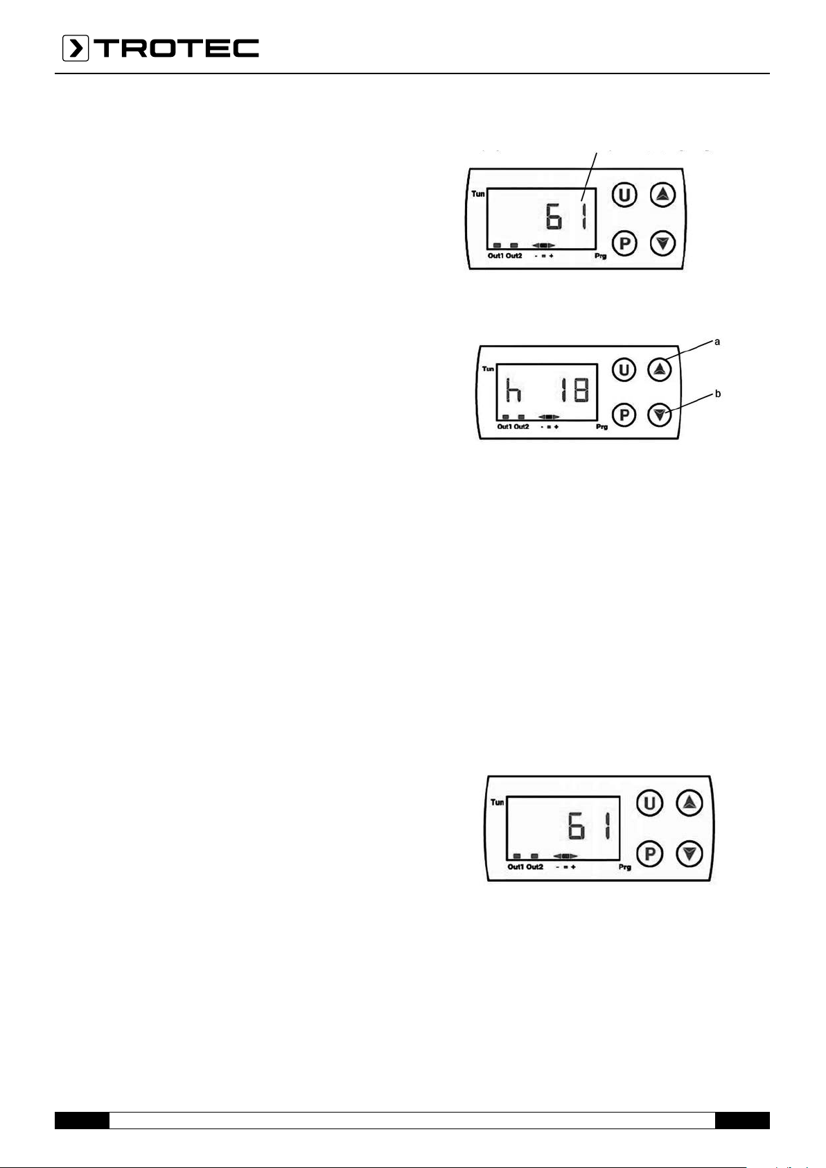
Detection of the air outlet temperature
The detected temperature [°C] is shown on the display:
Recording of the operating hours
If you press the button (a) twice, the operating time in hours[h] will
be displayed:
m The indicated time is not the effective heating time but
the time during which the device has been supplied with
current and switched on.
Proceed as follows to reset the counter:
• Turn the device's main switch to "0" (OFF).
• Press and hold the P button of the temperature controller for at
least three seconds. The word "PASS" flashes for five seconds.
• Enter the code "-481". To do so, repeatedly press the button(b)
until the desired character appears. Then press the P button to
confirm and move to the next character.
• Finally, press the U button: The air outlet temperature is displayed
again.
4.5 CONTROL OF THE TRIGGER TEMPERATURE OF THE FAN
THERMOSTAT
Control of the trigger temperature of the fan thermostat
4.4TEMPERATURE CONTROLLER
The air heater is equipped with a temperature controller (g) with
LCD display that can be used to display and control the following
parameters:
• Detection of the air outlet temperature
• Recording of the operating hours
• Control of the trigger temperature of the fan thermostat
• Control of the trigger temperature of the burner thermostat
The temperature controller is programmed in a way that it
automatically switches the main fan on or off depending on the
temperature set for the combustion chamber. This prevents cold air
from being blown out when the burner starts and the combustion
chamber is not yet sufficiently heated.
It also guarantees a discharge of the internal residual heat upon
switch-off.
The default temperature setting is 35°C with a hysteresis of 5°C.
A - 5 Operating manual – IDS 900 EN

The red "OUT1" LED indicates the operating condition of the fan
thermostat:
• When it is illuminated, the fan is running (ON);
• When it is not illuminated, the fan is switched off (OFF).
4.6 CONTROL OF THE TRIGGER TEMPERATURE OF THE BURNER
THERMOSTAT
Control of the trigger temperature of the burner thermostat
• Proper operation of the device requires regular maintenance
activities. Make sure that you disconnect the air heater from
the electrical power supply before starting these activities.
Maintenance
Measure
Check the air heater
Check the fuel oil supply line
Daily Weekly
x
x
Semi-
annually
Annually
The temperature controller is programmed in a way that it
automatically switches the burner on or off depending on the
maximum temperature set for the combustion chamber. This
prevents overheating of the combustion chamber and thus triggering
of safety thermostat L2, which would switch off the air heater (see
also "Faults and troubleshooting" chapter).
The default thermostat setting for the maximum temperature of the
combustion chamber is 95°C with a hysteresis of 5°C.
The red "OUT2" LED indicates the operating condition of the burner
thermostat: The LED sequence "- = +" indicates the current
temperature compared to the set temperature:
• If the red arrow above the "-" symbol lights up, the temperature
is below the set value and thus the thermostat enables operation
of the burner.
• If the green LED above the "=" symbol lights up, the temperature
equals the set value.
• If the red arrow above the "+" symbol lights up, the temperature
is above the set value and thus the thermostat disables operation
of the burner.
m The trigger temperatures of the fan thermostat and burner
thermostat can be modified. However, this should only
be done if it is absolutely necessary. For this purpose,
please contact the Trotec service to obtain the information
required for reprogramming the temperature controller.
Clean the outside of the device
Clean the motor and fan
Check the electrical connections
Check and test the burner
Check the thermostats
Clean the inside of the device
Inspect and clean the combustion
chamber
x
x
x
x
x
x
x
5.1 CHECKING THE AIR HEATER AND THE FUEL OIL SUPPLY LINE
Please check the following:
• Make sure that the device is not positioned in areas with a high
risk of fires or in potentially explosive atmospheres
• Make sure to maintain a safety distance from flammable
• substances
In case of fuel oil leaks:
• Close the fuel oil shut-off valve
• Locate and repair the fuel oil leak
• Do not use the machine until the removed panels have been
reattached
• Make sure that the room to be heated is sufficiently ventilated
• Make sure that the air intake and outlet pipes are not blocked in
any way
• Make sure that there are no sheets or blankets placed on the
device
• Make sure that the device is in a firm and stable position
• Make sure that the air heater is regularly monitored
during operation and checked prior to start-up
05. Care and maintenance
For a smooth operation of the device, the following tasks must be
performed regularly. Please note that the power supply of the air
heater must be interrupted beforehand.
m All operations described in this chapter must be carried out
by appropriately qualified personnel. Before starting work,
make the following preparations:
• Switch off the device as described above in the "SWITCHOFF" section.
• Cut off the power supply using the circuit breaker.
• Wait until the device has cooled down.
5.2 CLEANING THE OUTSIDE OF THE DEVICE
For a failure-free operation, we recommend that you clean the following parts:
• Burner:
- Thoroughly remove dirt and residues
- Make sure that the air inlet is not clogged
• Clean the housing, lines, pipes, connectors and joints with a cloth
• Air inlet/outlet:
- Thoroughly remove dirt and residues
- Make sure that the air inlet is not clogged
EN Operating manual – IDS 900 A - 6

5.3 CLEANING THE MOTOR AND THE FAN
To clean the fan wheel and the motor, please proceed as follows:
• Loosen the fastening screws of the fan and remove the fan.
• Clean the motor with compressed air.
• Clean the fan wheel with a hard brush.
• Reinstall the fan.
5.4 CHECKING THE ELECTRICAL CONNECTIONS
After unplugging the power supply cable, check all electrical
connections as follows:
• Make sure that the connections are intact and properly seated.
• Remove any dirt and corrosion or replace the connections if
necessary
• Replace damaged wires or connectors if necessary
5.5 CHECKING AND TESTING THE BURNER
To access the burner:
5.8 CLEANING THE HEAT EXCHANGER AND THE COMBUSTION
CHAMBER
To maintain the device's high efficiency, the cleaning work
described here must be performed at least once at the end of
each operating season, or several times in case of excessive soot
formation. The latter can occur, for instance, if the chimney draught
is not ideal, if low quality fuel is used, if the burner is improperly
adjusted, or if the device is switched on and off frequently.
06. Transport and repositioning
Hold the front handles when repositioning or transporting the device.
The heater will move on its rear wheels.
m Before repositioning the device, make the following prepara-
tions:
• Switch off the device.
• Interrupt the power supply by removing the plug from the
socket.
• Wait until the heater has cooled down.
• Unscrew the fastening screw of the burner
• Pull out the burner and perform the inspection and cleaning work
according to the instructions in the burner's operating manual
• Reattach the burner unit
• Perform the work steps required to measure the combustion
parameters and ensure a stable and clean combustion, which are
described in chapter4
5.6 CHECKING THE THERMOSTATS
Proceed as follows to check the thermostats:
• Remove any connection ducts from the air outlet
• Locate the thermostats mounted on the inner wall of the air heater
• Clean the thermostats with a dry cloth and pay attention not to
kink or damage the capillary tube
5.7 CLEANING THE INSIDE OF THE DEVICE
For thorough cleaning the air heater can be washed with water both
on the inside and on the outside.
However, you have to observe the following:
• The power cable must be removed from the socket
• All inspection panels must be completely closed
• When cleaning with a water jet, the maximum permissible
pressure is 70 bar with a distance below 30 cm
• All parts must have dried completely before the power cable is
reconnected
Only use the provided lifting gear for lifting the device. Attach ropes
or chains to the four lifting points. Before lifting the device make sure
that the lifting gear used is actually suited to lift the device. You will
find the weight of the device in the technical data table.
m Do not try to lift the device with pure muscle power: The
heavy weight can cause serious physical damage.
07. Fault and troubleshooting
In case of a severe operational disruption, various safety devices can
cause a safety shutdown of the device. This is signalised as follows:
• at the control box
This is the block signal indicating that safety thermostatL2
has triggered. The reset button is located inside the burner
housing.
• at the burner
Safety shutdown signal indicating that the burner's flame
monitoring has triggered.
m In the event of a safety shutdown, do not carry out two
consecutive restarts. Unburned fuel components can accumulate in the combustion chamber and might suddenly
ignite during the subsequent restart.
If the inspections and corrective measures do not produce any results, please contact your nearest sales and service centre.
A - 7 Operating manual – IDS 900 EN

Malfunction Cause Troubleshooting
• Device does not start
• No power supply
• Incorrect main switch position
• Room thermostat only functions
sporadically
• The safety system (burner,
thermostat L2, thermal relay of
the fan) was not reset after repair
• Overheating of the combustion
chamber
• Tripping of thermostat L2 (warning
light (9) lights up)
• Tripping of thermal relay RM
(light (10) lights up)
• Overheating of the combustion
chamber
• Excessive power consumption of
the fan motor
• Check the functioning and position of the
switch
• Check the characteristics of the electrical line
• Check the electrical connections
•
Check whether the fuses are intact
• Set to the right position
• Check and correct the thermostat position
• Check whether the thermostat is operational
• Press the reset button:
• Burner (button on control system)
• Thermostat L2 (button (6))
• Thermal relay of the fan (button (11))
• Check fuel supply• Tripping of thermostat L1
• Check the correct positioning of any flaps,
nozzles etc.
• Remove any parts which might be stuck in the air
ducts or ventilation grilles
• Check as described above
• If unsuccessful, please contact your supplier
• Heater with axial fan: Remove any obstacles from
the air intake. Reduce the lengths of the air ducts
• The burner starts, the flame does
not ignite and the reset indicator on
the control system is illuminated
• The fan does not start or starts with a
delay
• The fan makes noises or vibrates
• Irregular operation of the burner
• No power supply
• Thermostat F damaged
• Motor winding burnt or
interrupted
• Motor capacitor burnt
(Mod. "M")
• Motor bearing blocked
• Foreign objects on fan blades
• Insufficient air circulation
• Heater with centrifugal fan: Check the fan belt
setting as described in the "CONNECTION TO
AIR DUCTS" chapter
• In any case check that the power consumption is
lower than the value indicated on the nameplate
• Should this situation reoccur after pressing the
restart button and starting the device, please contact
the technical customer service
• Check whether the fuses are intact
• Check the electrical connections
• Check, adjust or exchange the thermostat
• Exchange fan motor
• Exchange capacitor
• Exchange bearing
• Remove foreign objects
• Remove any obstacles affecting air circulation
• Insufficient heating
• Insufficient heat output of the
burner
• Please contact the technical customer service
EN Operating manual – IDS 900 A - 8

08. Functional diagram and control panel
1 USCITA ARIA CALDA
SORTIE AIR CHAUD
WARMLUFTAUSTRITT
HOT AIR OUTFLOW
SALIDA DE AIRE CALIENTE
ВЫХОДГОРЯЧЕГОВОЗДУХА
2 CAMINO
CHEMINEE
SCHORNSTEIN
CHIMNEY
CHIMENEA
ДЫМОХОД
3 VENTILATORE RAFFREDDAMENTO
VENTILATEUR REFROIDISSEMENT
KÜHLVENTILATOR
COOLING FAN
VENTILADOR DE ENFRIAMIENTO
ВЕНТИЛЯТОРОХЛАЖДЕНИЯ
4 CAMERA DI COMBUSTIONE
CHAMBRE DE COMBUSTION
BRENNKAMMER
COMBUSTION CHAMBER
CÁMARA DE COMBUSTIÓN
КАМЕРАСГОРАНИЯ
5 BRUCIATORE
BRULEUR
BRENNER
BURNER
QUEMADOR
ГОРЕЛКА
6 SCAT OLA TERMOSTATI L2
BOITIER THERMOSTATS L2
THERMOSTATGEHÄUSE L2
THERMOSTATS L2 BOX
CAJA DE TERMOSTATOS L2
КОРОБКАТЕРМОВЫКЛЮЧАТЕЛЕЙL2
7 STAFFE DI SOLLEVAMENTO
ÉTRIERS DE LEVAGE
TRAGWANGEN
HOISTING BRACKETS
SOPORTES DE ELEVACIÓN
ПОДЪЕМНЫЕКРОНШТЕЙНЫ
8 PIEDE / MANIGLIA
SUPPORT/POIGNEE
STUTZE/HANDGRIFF
SUPPORT/HANDLE
AYUDA Y MANIJA
НОЖКА/РУЧКА
9 RUOTA
ROUE
RAD
WHEEL
RUEDA
КОЛЕСО
10 SCATOLA BRUCIATORE
BOÎTIER BRÛLEUR
BRENNERGEHÄUSE
BURNER BOX
CAJA DEL QUEMADOR
КОЖУХГОРЕЛКИ
11 PARAURTI
PARE-CHOCS
PUFFER
BUFFER
PARACHOQUES
АМОРТИЗИРУЮЩИЕПРОКЛАДКИ
12 SCATOLA QUADRO ELETTRICO
BOÎTIER TABLEAU ÉLECTRIQUE
SCHALTKASTEN
ELECTRICAL PANEL BOX
CAJA DEL CUADRO ELÉCTRICO
КОЖУХЭЛЕКТРОШКАФА
A - 9 Operating manual – IDS 900 EN

a INTERRUTTORE RISCALDAMENTO-VENTILAZIONE
INTERRUPTEUR CHAUFFAGE-VENTILATION
SCHALTER HEIZUNG-LÜFTUNG
HEATING-VENTILATION SWITCH
INTERRUPTOR CALEFACCION/VENTILACION
ПЕРЕКЛЮЧАТЕЛЬНАГРЕВА-ВЕНТИЛЯЦИИ
b LAMPADA TENSIONE
TEMOIN TENSION
LEUCHTE SPANNUNG
VOLTAGE LAMP
TESTIGO TENSIÓN
ИНДИКАТОРНАПРЯЖЕНИЯ
c LAMPADA TERMOSTATI DI SICUREZZA L2
TEMOIN THERMOSTATS DE SURCHAUFFE, L2
KONTROLLLEUCHTE SICHERHEITSTHERMOSTATE L2
OVERHEAT THERMOSTATS CONTROL LAMP, L2
TESTIGO TERMOSTATOS DE SEGURIDAD, L2
ИНДИКАТОРПРЕДОХРАНИТЕЛЬНЫХ
ТЕРМОВЫКЛЮЧАТЕЛЕЙL2
d PRESA PER TERMOSTATO AMBIENTE
PRISE THERMOSTAT D’AMBIANCE
RAUMTHERMOSTAT STECKDOSE
ROOM THERMOSTAT PLUG
ENCHUFE TERMOSTATO AMBIENTE
РАЗЪЕМДЛЯТЕРМОСТАТАОКРУЖАЮЩЕЙСРЕДЫ
e PRESA PER FILTRO PRERISCALDO
PRISE POUR FILTRE PRÉCHAUFFAGE
ANSCHLUSS FÜR FILTER VORWÄRMANLAGE
INTAKE FOR PRE-HEAT FILTER
TOMA PARA FILTRO DE PRECALENTAMIENTO
ГНЕЗДОДЛЯФИЛЬТРАПОДОГРЕВА
f PRESSACAVO PER CAVO ALIMENTAZIONE
PRESSE-CÂBLES POUR CÂBLE D‘ALIMENTATION
KABELDURCHFÜHRUNG FÜR STROMVERSORGUNGSKABEL
CABLE CLAMP FOR POWER CABLE
PRENSACABLE PARA CABLE DE ALIMENTACIÓN
КАБЕЛЬНАЯВТУЛКАДЛЯСИЛОВОГОКАБЕЛЯ
g TERMOREGOLATORE
THERMORÉGULATEUR
TEMPERATURREGLER
TEMPERATURE CONTROLLER
TERMORREGULADOR
ТЕРМОРЕГУЛЯТОР
h LAMPADA BRUCIATORE
VOYANT BRÛLEUR
BRENNERANZEIGE
BURNER LIGHT
TESTIGO DEL QUEMADOR
ИНДИКАТОРГОРЕЛКИ
LAMPKA SYGNALIZACYJNA PALNIKA
i PULSANTE DI RIARMO TERMOSTATO DI SICUREZZA, L2
POUSSOIR DE RÉARMEMENT THERMOSTAT DE SÉCURITÉ, L2
ENTSTÖRTASTE DES SICHERHEITSTHERMOSTATEN, L2
SAFETY THERMOSTAT RESET BUTTON, L2
BOTÓN DE REARME DEL TERMOSTATO DE SEGURIDAD, L2
КНОПКАСБРОСАПРЕДОХРАНИТЕЛЬНОГОТЕРМОВЫКЛЮЧАТЕЛЯ,L2
l LAMPADA BLOCCO VENTILATORE (solo per modelli trifase)
TÉMOIN BLOCAGE VENTILATEUR (uniquement pour modèles triphasés)
KONTROLLLEUCHTE SICHERHEITSABSCHALTUNG DES VENTILATORS (nur Modelle mit
3-Phasen-Betrieb)
FAN BLOCK LAMP (for 3-phase models only)
TESTIGO BLOQUEO VENTILADOR (sólo para modelos trifásicos)
ИНДИКАТОРБЛОКИРОВКИВЕНТИЛЯТОРА(толькодлятрехфазныхмоделей)
m LAMPADA / PULSANTE DI RIARMO BRUCIATORE
TÉMOIN / POUSSOIR DE RÉARMEMENT
BRÛLEUR
LAMPE / ENTSTÖRTASTE BRENNER
BURNER RESET BUTTON / LAMP
TESTIGO/BOTÓN DE REARME DEL QUEMADOR
ИНДИКАТОР/КНОПКАСБРОСАГОРЕЛКИ
n PANNELLO SCATOLA QUADRO ELETTRICO
PANNEAU BOÎTIER TABLEAU ÉLECTRIQUE
ABDECKUNG SCHALTKASTEN
ELECTRICAL PANEL BOX PANEL
PANEL DE LA CAJA DEL CUADRO ELÉCTRICO
ПАНЕЛЬКОЖУХАЭЛЕКТРОШКАФА
o QUADRO ELETTRICO
TABLEAU ÉLECTRIQUE
SCHALTKASTEN
ELECTRICAL PANEL
CUADRO ELÉCTRICO
ЭЛЕКТРОШКАФ
EN Operating manual – IDS 900 A - 10
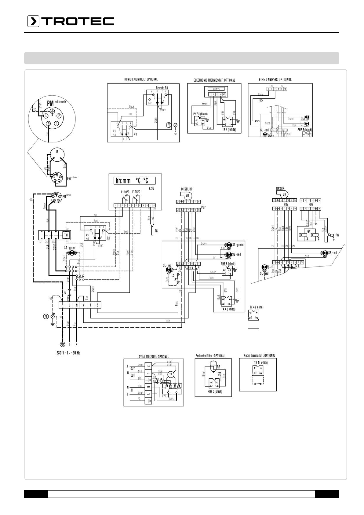
09. Circuit diagram
C Capacitor
M Fan motor
F Air controller
FB Fuse for burner 6A
TM Remote switch for fan
RM Thermal relay for fan
ST Indicator light
SB Fan "OFF" indicator light
A - 11 Operating manual – IDS 900 EN
BR Burner
TA Room thermostat
PB Burner
L1 Overheating protection thermostat, L1
L2 Safety thermostat with manual release, L2
RV Switch heating-stop-ventilation
SL Overheating protection indicator light, L1, L2

10. Technical data
Article number
Air flow rate
Fan
Max. nominal heat input
Nominal heat output
Temperature increase* (ΔT)
Input voltage
Current consumption
Max. oil consumption
Air transport hose connector ø
Chimney connection ø
Thermostat connection
Tank contents
Sound level (distance 1m)
Length
Width
Height
Weight kg
Combustion
1.430.000.160
Type IDS 900
12,500 m³/h
axial fan
235 kW
221 kW (181,427 kcal)
47 °C
230 V / 50 Hz
12 A
21.67 l/h
1 x 700 mm** 2 x 600 mm** 4 x 400 mm**
200 mm
standard
208 l
81.3 dB(A)
2,245 mm
982 mm
1,584 mm
351 kg
indirect
* ΔT indicates the temperature increase. The outlet air temperature is calculated from ΔT + ambient temperature.
** Optionally available accessories required.
EN Operating manual – IDS 900 A - 12

11. Available accessories
Accessory Article number
Hose
connector
Two-way
hose distributor
Four-way
hose distributor
Thermostat
with 10 m cable
Connection kit
for external oil tank
Oil pre-heating
Filler neck oil filter
1 x ø 700 mm,
standard equipment
2 x ø 600 mm,
Article no. 6.100.006.174
4 x ø 400 mm,
Article no. 6.100.006.175
Article no.
6.100.007.016
Standard equipment
Article no.
6.100.006.177
Article no.
6.100.006.161
Oil tank pedestal IDS900,
capacity 208 litres
Exhaust gas pipe rigid,
length 1 m
90° arc connection
for exhaust gas pipe
Exhaust gas pipe
rain cover
Air hose Tronect
SP-C³, length 7.6m
Article no.
6.100.006.176
Article no.
6.100.006.214
Article no.
6.100.006.220
Article no.
6.100.006.226
Article no.
6.100.001.273
A - 13 Operating manual – IDS 900 EN

EN Operating manual – IDS 900 A - 14

Trotec GmbH & Co. KG
Grebbener Str. 7
D-52525 Heinsberg
+49 2452 962-400
+49 2452 962-200
info@trotec.com
www.trotec.com
 Loading...