

Page 1
BB20
EN
OPERATING MANUAL
LAYER THICKNESS
MEASURING DEVICE
TRT-BA-BB20-TC2019-05-001-EN
Page 2
Table of contents
Notes regarding the operating manual................................. 2
Safety .....................................................................................2
You can download the current version of the operating manual
and the EU declaration of conformity via the following link:
Information about the device................................................3
Transport and storage...........................................................5
Operation ...............................................................................5
Menu structure ....................................................................10
PC software..........................................................................11
Errors and faults..................................................................11
Maintenance and repair ......................................................11
Disposal ...............................................................................12
Notes regarding the operating manual
Symbols
Warning of electrical voltage
This symbol indicates dangers to the life and health of
persons due to electrical voltage.
Warning
This signal word indicates a hazard with an average
risk level which, if not avoided, can result in serious
injury or death.
Caution
This signal word indicates a hazard with a low risk
level which, if not avoided, can result in minor or
moderate injury.
Note
This signal word indicates important information (e.g.
material damage), but does not indicate hazards.
Info
Information marked with this symbol helps you to carry
out your tasks quickly and safely.
Follow the manual
Information marked with this symbol indicates that the
operating manual must be observed.
BB20
https://hub.trotec.com/?id=43284
Safety
Read this manual carefully before starting or using the
device. Always store the manual in the immediate vicinity
of the device or its site of use!
Warning
Read all safety warnings and all instructions.
Failure to follow the warnings and instructions may
result in electric shock, fire and/ or serious injury.
Save all warnings and instructions for future
reference.
This appliance can be used by children aged from
8years and above and persons with reduced physical,
sensory or mental capabilities or lack of experience
and knowledge if they have been given supervision or
instruction concerning use of the appliance in a safe
way and understand the hazards involved.
Children shall not play with the appliance. Cleaning and
user maintenance shall not be made by children
without supervision.
• Do not use the device in potentially explosive rooms.
• Do not use the device in aggressive atmosphere.
• Protect the device from permanent direct sunlight.
• Do not remove any safety signs, stickers or labels from the
device. Keep all safety signs, stickers and labels in legible
condition.
• Do not open the device.
• Observe the storage and operating conditions as given in
the Technical data chapter.
Intended use
Only use the device for coating thickness measurements.
Observe and comply with the technical data.
To use the device for its intended use, only use accessories and
spare parts which have been approved by Trotec.
2 EN
layer thickness measuring device BB20
Page 3
Improper use
1
2
8
7
9
5
4
3
10
6
Do not use the device in potentially explosive atmospheres, for
measurements in liquids or at live parts. Trotec accepts no
liability for damages resulting from improper use. In such a
case, any warranty claims will be voided. Any unauthorised
modifications, alterations or structural changes to the device are
forbidden.
Personnel qualifications
People who use this device must:
• have read and understood the operating manual, especially
the Safety chapter.
Residual risks
Warning
Risk of suffocation!
Do not leave the packaging lying around. Children may
use it as a dangerous toy.
Warning
The device is not a toy and does not belong in the
hands of children.
Information about the device
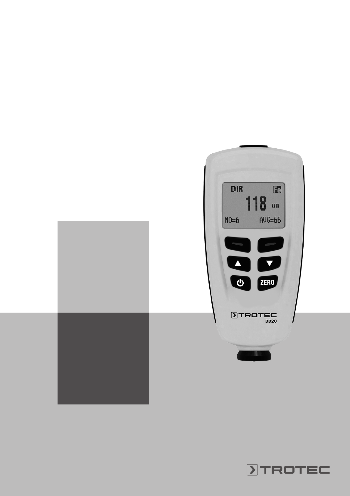
Device description
The deviceBB20 is used to determine the coating thickness on
ferromagnetic and non-ferromagnetic metal surfaces. The
measuring device functions according to the magnetic induction
principle (for coatings on ferromagnetic surfaces) or the
turbulent flow principle (for coatings on non-ferromagnetic
surfaces).
The BB20 is a compact and versatile device suitable for quick,
precise and non-destructive measurements of coating
thicknesses.
Device depiction
Warning
Dangers can occur at the device when it is used by
untrained people in an unprofessional or improper way!
Observe the personnel qualifications!
Caution
Keep a sufficient distance from heat sources.
Note
To prevent damages to the device, do not expose it to
extreme temperatures, extreme humidity or moisture.
Note
Do not use abrasive cleaners or solvents to clean the
device.
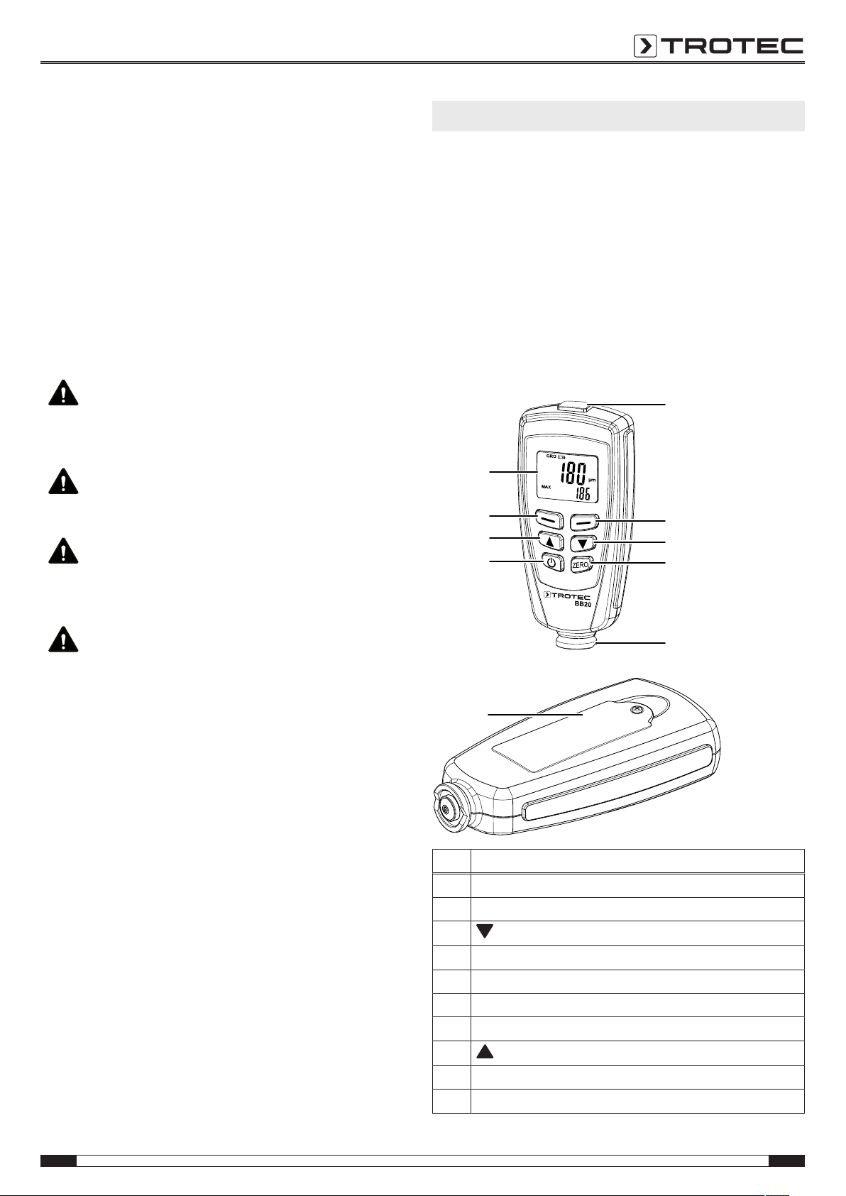
No. Designation
1 USB interface
2 Blue button (back/ cancel)
3
button
4 ZERO button
5 Sensor
6 Battery compartment with cover
7 Power button
8
button
9 Red button (select/ confirm)
10 Display
EN 3
layer thickness measuring device BB20
Page 4
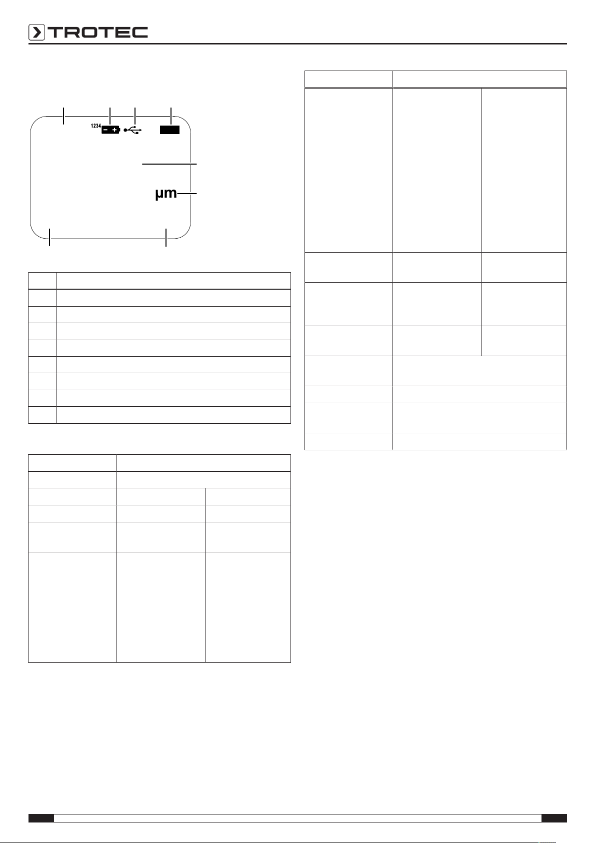
Display
DIR GRO
NO=3 MAX=63
NFe
58
18 17
16
15
14
13
11
12
No. Designation
11 Working mode display
12 Battery indication
13 PC access display
14 NFe/Fe display
15 Indication of the unit
16 Layer thickness display
17 Statistical data display: AVG, MAX, MIN, SDEV
18 Number of measured values
Technical data
Parameter Value
Accuracy 0 to 50μm
(0.1μm)
50 to 850μm
(1μm)
850 to 1250μm
(0.01mm)
0 to 1.968mils
(0.001mils)
1.968 to 33.46mils
(0.01mils)
33.46 to 49.21mils
(0.1mils)
Minimum bending
radius
Diameter of the
smallest measuring
surface
Critical primary layer
thickness
Ambient temperature
Power supply 2 batteries 1.5 V AAA
Dimensions (length
x width x height)
Weight 152 g
1.5 mm 3 mm
7 mm 5 mm
0.5μm 0.3μm
0 to 40°C (32 to 104°F) at 20 to
90%RH
114x 27x 54 mm
0 to 50μm
(0.1μm)
50 to 850μm
(1μm)
850 to 1250μm
(0.01mm)
0 to 1.968mils
(0.001mils)
1.968 to 33.46mils
(0.01mils)
33.46 to 49.21mils
(0.1mils)
Parameter Value
Model BB20
Sensor
Functional principle Magnetic induction Turbulent flow
Measuring range 0 to 1250 μm
Guaranteed
tolerance (of the
measured value)
F N
0 to 49.21 mils
0 to 850μm
(±3 % ±1μm)
850 to 1250μm
(±5 %)
0 to 33.46mils
(±3 % ±0.039mils)
33.46 to 49.21mils
(±5 %)
0 to 1250 μm
0 to 49.21 mils
0 to 1000μm
(±3 % ±1.5μm)
850 to 1250μm
(±5 %)
0 to 33.46mils
(±3 % ±0.059mils)
33.46 to 78.7mils
(±5 %)
Scope of delivery
• 1 x Layer thickness measuring device BB20
• 2 x 1.5 V batteries AAA
• 1 x Transport case
• 1xSteel and aluminium base plate with different film
thicknesses for calibration
• 1 x USB cable
• 1x Operating manual
• 1x PCsoftware
4 EN
layer thickness measuring device BB20
Page 5

Transport and storage
Operation
Note
If you store or transport the device improperly, the
device may be damaged.
Note the information regarding transport and storage of
the device.
Transport
For transporting the device, use the transport case included in
the scope of delivery in order to protect the device from external
influences.
Storage
When the device is not being used, observe the following
storage conditions:
• dry and protected from frost and heat
• protected from dust and direct sunlight
• For storing the device, use the transport case included in
the scope of delivery in order to protect the device from
external influences.
• The storage temperature is the same as the range given in
the Technical data chapter.
• Remove the batteries from the device.
Inserting the batteries
• Insert the supplied batteries before first use.
1. Loosen the screw and open the battery compartment(6).
2. Insert the new batteries in the battery compartment(6)
with correct polarity.
3. Place the cover back on the battery compartment(6) and
reinsert the screw.
Switching the device on
Info
Note that moving from a cold area to a warm area can
lead to condensation forming on the device's circuit
board. This physical and unavoidable effect can falsify
the measurement. In this case, the display shows
either no measured values or they are incorrect. Wait a
few minutes until the device has become adjusted to
the changed conditions before carrying out a
measurement.
1. Press the Power button(7).
ð The display will be switched on and the device ready for
operation.
Menu
Press the Red button(9) to open the main menu.
Press the (3) or button(8) to select the desired menu
item.
In order to confirm the selected menu item, press the Red
button(9) again.
Press the Blue button(2) to return to the previous menu item.
EN 5
layer thickness measuring device BB20
Page 6

Setting the measuring mode
To adjust the measuring mode, please proceed as follows:
1. Press the Red button(9) to open the main menu.
2. In the menu, select the menu item Options and confirm by
pressing the Red(9) button.
3. Select the Measure mode menu item, then, select the
desired mode. Confirm with the Redbutton(9).
Single mode:
After every measurement, an acoustic signal will be emitted. All
measurements are automatically saved.
Continuous mode:
The sensor must not be lifted between the individual
measurements. No acoustic signal will be emitted after the
measurement. All measurements are automatically saved.
Setting the working mode
To set the working mode, please proceed as follows:
1. Press the Red button(9) to open the main menu.
2. In the menu, select the menu item Options and confirm by
pressing the Red(9) button.
3. Select the Working mode menu item, then, select the
desired mode. Confirm with the Redbutton(9).
The device offers two different working modes:
DIRECT:
This mode is suitable for quick and easy measurements.
Measurements are cached during a measurement series.
Once the device is switched off or changes into another working
mode, the measurement results will be deleted. The statistical
analysis programme is able to assess80measurements. Once
the memory is full, the oldest measurements will be overwritten.
GROUP:
The GROUP mode comprises group1to4. In each group,
80individual and 5statistical measurements can be saved.
Calibration and limit values can be adjusted and saved
individually.
Once the memory is full, current measurements will no longer
be saved. Measurements can be carried out as usual.
Setting the sensor mode
To adjust the sensor mode, please proceed as follows:
1. Press the Red button(9) to open the main menu.
2. In the menu, select the menu item Options and confirm by
pressing the Red(9) button.
3. Select the Used probe menu item, then, select the desired
mode. Confirm with the Redbutton(9).
• AUTO:
The sensor automatically selects a measuring mode.
• Fe:
The sensor operates according to the magnetic induction
principle if it is placed on a magnetic surface.
• Not Fe:
The sensor operates according to the turbulent flow
principle if it is placed on non-magnetic metals.
Units
You can choose between metric (μm and mm) and
imperial(mils) units.
If the measured value exceeds850μm, the device switches to
mm.
To change the unit, proceed as follows:
1. Press the Red button(9) to open the main menu.
2. In the menu, select the menu item Options and confirm by
pressing the Red(9) button.
3. Select the Unit setting menu item, then, select the desired
unit. Confirm with the Redbutton(9).
Reset
Resetting deletes the entire data in all memories. In order to
carry out a reset, follow these steps:
1. Switch the device off.
2. Simultaneously press the Zero button(4) and the Power
button(7).
ð sure to reset will be displayed.
3. Press the Red button(9) to confirm or the Blue button(2) to
cancel the process.
The device automatically switches back on.
Background illumination
In the menu, you can control the background illumination using
Options and Backlight, during a measurement, use the
Bluebutton(2).
6 EN
layer thickness measuring device BB20
Page 7

Indication of statistics
In the menu item LCD Statistic, you can choose between the
following indications:
• Average
• Maximum
• Minimum
• Standard deviation (Sdev.)
The selected indication appears in the bottom right corner of the
display in the statistical data indication(17).
Statistics of the measured values appear on the bottom left
corner in the display in the measured values indication(18).
To view all statistical values of the respective groups, go to the
menu and select Statisticview.
Measured value indication
To view all measured values of the respective groups, go to the
menu and select Measureview.
Automatic switch-off
The device switches off after 3 minutes of inactivity. To
deactivate automatic switch-off, go to the Options section in the
menu and select the Auto poweroff function. Select Disable and
confirm by pressing the Red(9) button.
Device calibration
Carry out a calibration before each measuring operation.
You can perform the calibration e.g. at an untreated or uncoated
spot of the object to be tested or use the set included in the
scope of delivery.
Calibration mode
1. Press the Red button(9) to open the main menu.
2. Select the Calibration menu item, then select Enable.
ð You return automatically back to Calibration.
3. Press the Blue button(2) to return back to the start screen.
Calibration is carried out here.
ð The following messages appear on the display:
• cal zero: There is no one-point or two-point calibration.
• cal1to2: There is a one-point or two-point calibration.
• zeroy: There is a zero-point calibration.
Info
Please bear in mind that the device at hand is a
precision measuring device that can determine coating
thicknesses of no more than a few micrometres (1µm
is equivalent to one thousandth of a millimetre).
The surface condition of most measuring objects is
hardly ever perfectly even and homogeneous, even
though it might appear differently to the naked eye.
Observed under the microscope, even the smoothest
surface looks much like a mountain and valley
landscape. The teensiest of scratches, cavities or
contaminations can therefore already have a negative
effect on the expected measurement result, seeing as
they will also be a part of the measurement to a
greater or lesser extent. It does, however, not affect
the accuracy of the device. Even after the calibration
unexpected measurement deviations of a few
micrometres always have to be regarded in this
context.
Hence it is important to handle the supplied calibration
accessories with care to avoid scratches and dirt on
their respective surface as far as possible.
EN 7
layer thickness measuring device BB20
Page 8

Zero point calibration
ü An uncoated sample is required.
1. Place the sensor onto an uncoated sample. The calibration
sample is to be identical with the actual sample in terms of
material composition, shape and surface condition.
ð The following message will be displayed:
<x.x μm>
2. Lift the sensor again and keep it away from the sample (at
least 10cm).
3. Press and hold the Zero button(4) for approx. 2seconds.
ð The following result appears on the display:
<0.0μm>
CAL1
ZeroY
ð The calibration is terminated.
One-point calibration
This calibration is suited for high-precision measurements, e.g.
for thin coatings.
ü A calibration film, a coated and an uncoated sample are
required.
1. Activate the calibration mode as described before.
2. Carry out a zero-point calibration.
3. Place the calibration film on an uncoated sample.
4. Place the sensor on the sample.
ð The measurement is effected.
5. Lift the sensor again.
6. Adjust the required film thickness by using the Down/
Right(3) or the Up/Left(8) button. The film thickness
should be at least the size of the estimated coating
thickness.
7. Repeat this step several times.
8. Now carry out the measurement on a coated sample.
9. Press the Zero button(4) to adopt the current calibration.
10. To exit the current calibration, press the Blue button(2).
Two-point calibration
This calibration is especially suited for measurements on rough
surfaces or for high-precision measurements.
ü You need two films of different film thickness. The thicker
film should be approx.1.5 times thicker than the thinner
film.
1. At first, carry out a zero-point calibration.
2. Using the first film, carry out a one-point calibration.
3. Repeat this step with the second film.
4. Place the sensor onto the coating that is to be measured.
After a brief acoustic signal is emitted, you can lift the
sensor again.
ð The measured value appears on the display.
Calibration on radiated surfaces
Values of layer thickness measurements carried out on radiated
surfaces are usually too high. The average thickness can be
determined as follows:
Method A
1. Carry out the steps for one-point and two-point calibration
as described above. Use a smooth sample with the same
surface curvature and material type as the measuring
object that is to be used later on.
2. In order to determine the average value Xo, carry out
approx.10 measurements on the uncoated sample.
3. Afterwards, carry out approx.10 measurements on the
coated sample to determine the average value Xm.
ð The difference between both average values is the
average coating thickness Xeff. Take the standard
deviation of both values Xm and Xo into account.
Xeff= (Xm - Xo)±S
Method B
1. Carry out a zero calibration with approx.10measurements
on an uncoated sample.
2. Afterwards, carry out a film calibration on the uncoated
sample.
3. Repeat this calibration with films of different thicknesses
(max. thickness50μm). Together, these films should be as
thick as the assumed layer thickness.
ð The layer thickness can be read from the display.
Method C
1. Carry out the steps for two-point calibration with two films
as described above.
2. Use several 50μm films to approach the actual surface as
precisely as possible.
ð The layer thickness can be read from the display.
8 EN
layer thickness measuring device BB20
Page 9

General information on measurements
If the calibration has been carried out correctly, the measured
value lies within the guaranteed measuring tolerance. Incorrect
measured values can be deleted in the menu. The last value
results from the statistical calculation and the guaranteed
degrees of tolerance of the measured value.
Strong electrical or electromagnetic fields can influence the
measured values.
The measuring tip is to be cleared of contamination prior to
each calibration.
Wait for at least 4seconds after each measurement before
proceeding to the next measurement as the device does not
respond to measurement sequences carried out too quickly.
Deleting functions
In order to delete measured values, select Delete in the menu,
then select the measured values you would like to delete.
• Current Data
Deletes the last measured value.
• All Data
All data can be deleted during the respective working
mode.
• Group Data
Comprises Delete all data. In addition, the limit values and
one-point and two-point calibration values will be deleted.
Statistical measurements
The device is able to calculate statistics based on
80measurements. A total of 400measured values can be
saved.
No measured values are saved in direct mode, however,
calculating statistics is possible.
If you change between the different working modes or if the
device is switched off, statistics are deleted from the direct
mode.
The following statistical values are calculated:
• NO.: Number of measured values in working mode
• AVG: Average
• Sdev.: Standard deviation
• MAX: Maximum value
• MIN: Minimum value
Memory space full
If the memory space is full in group mode, statistics will no
longer be updated. However, measurements can still be carried
out. These measurements will not be part of the statistics.
In single measurement mode, FULL appears on the display.
If the memory space is full in direct mode, old measurements
are replaced by new ones and statistics will be updated.
Limit value functions
Limit values can be entered using the Limit function. It is
possible to enter limit values before, during or after carrying out
measurement series.
1. Press the Red button(9) to open the main menu.
2. Select the Limit menu item, then select Limit setting.
ð Using the (3) and (8) buttons, you can
determine the upper limit value in the High limit section
and the lower limit value in the Low limit section.
Each measured value beyond the fixed tolerance limit appears
on the display as follows:
H: Measured value is above upper limit value.
L: Measured value is below lower limit value.
EN 9
layer thickness measuring device BB20
Page 10

Menu structure
Main menu Submenu 1 Submenu 2
Statistic view
(Statistic view)
Options Measuring mode Single mode
Limit values (Limit) Limit value settings
Average view
Minimum view
Maximum view
Number view
Standard deviation
view (Sdev.view)
Working mode
(Working mode)
Used probe
(Used probe)
Units
(Unit setting)
Background illumination (Back-
light)
LCD Statistic
LCDStatistic
Automatic switchoff (Autopoweroff)
(Limitsettings)
Delete limit value
(Delete limit)
-
Continuous mode
Direct
Group 1
Group 2
Group 3
Group 4
AUTO
Fe
Not Fe
μm
mils
mm
On
Off
Average
Maximum
Minimum
Standard deviation
Activate
Deactivate
Upper limit value
Lower limit value
-
Main menu Submenu 1 Submenu 2
Delete Current data -
All data
Group data
Measured value
- indication (Measure
view)
Calibration Activate (Enable) -
Deactivate
(Disable)
Delete zeroN
Delete zeroF
10 EN
layer thickness measuring device BB20
Page 11

PC software
Errors and faults
Using the software CoatingThicknessTester stored
measurement data can be called up and saved via USB cable.
The software is available for download at www.trotec.de.
Info
The supplied free software is designed for useful basic
functionalities. Trotec assumes no liability with regard
to this free software and also provides no support on
that score. Trotec accepts no liability concerning the
use of this free software and is under no obligation to
make adjustments or to further develop updates or
upgrades.
Installation requirements
Ensure that the following minimum requirements for installing
the PC software are fulfilled:
• Supported operating systems:
– Windows 7
– Windows 8
– Windows 8.1
– Windows 10
• Hardware requirements:
– Standard USB interface
– Min. 7MB of free hard disk space
– Recommended resolution: 1280*1024 with16bit
– .NET Framework 2.0 or higher
The device has been checked for proper functioning several
times during production. If malfunctions occur nonetheless,
check the device according to the following list.
The device does not switch on:
• Check the charging status of the batteries. Change the
batteries, if required.
• Check that the batteries are properly positioned. Check the
polarity is correct.
• Never carry out an electrical check yourself; instead,
contact your Trotec customer service.
Table of faults
The following error codes can be displayed:
Error code Cause of error
Err1, Err2, Err3 Faulty contact between sensor and
mainboard
Err1 Faulty signal of eddy-current sensor
Err2 Faulty signal of magnetic induction sensor
Err3 Faulty signals of both sensors
Err4, Err5, Err6 No meaning, reserved for later versions of
the device
Err7 Faulty measurement. There might be a
hardware problem.
Installing the PC software
1. Insert the data medium with the software into the drive or
download the current software from the Service area of
Trotec download centre.
2. Double-click the installation file Setup.exe.
3. Follow the instructions of the installation wizard.
Starting the PC software
1. Connect the device to the PC using the supplied USB cable.
2. Start the PC software.
ð The software connects to the device.
ð Data stored on the device can now simply be visualised
in form of a chart or graphic.
Saving measured values (export)
You can export a selected group as csv or txt file and save it on
your PC. There the table looks as it does in the software.
1. Open the desired file.
2. You select either Save *.TXT or Save *.CSV.
Maintenance and repair
Battery change
A battery change is required, when the battery indication(12)
lights up or the device can no longer be switched on. See
chapter Operation
Cleaning
Clean the device with a soft, damp and lint-free cloth. Make
sure that no moisture enters the housing. Do not use any
sprays, solvents, alcohol-based cleaning agents or abrasive
cleaners, but only clean water to moisten the cloth.
Repair
Do not modify the device or install any spare parts. For repairs
or device testing, contact the manufacturer.
EN 11
layer thickness measuring device BB20
Page 12

Disposal
The icon with the crossed-out waste bin on waste
electrical or electronic equipment stipulates that this equipment
must not be disposed of with the household waste at the end of
its life. You will find collection points for free return of waste
electrical and electronic equipment in your vicinity. The
addresses can be obtained from your municipality or local
administration. For further return options provided by us please
refer to our website https://de.trotec.com/shop/.
The separate collection of waste electrical and electronic
equipment aims to enable the re-use, recycling and other forms
of recovery of waste equipment as well as to prevent negative
effects for the environment and human health caused by the
disposal of hazardous substances potentially contained in the
equipment.
In the European Union, batteries and accumulators must not be
treated as domestic waste, but must be disposed of
professionally in accordance with Directive 2006/66/EC of the
European Parliament and of the Council of 6September 2006
on batteries and accumulators. Please dispose of batteries and
accumulators according to the relevant legal requirements.
12 EN
layer thickness measuring device BB20
Page 13

Trotec GmbH
Grebbener Str. 7
D-52525 Heinsberg
+49 2452 962-400
+49 2452 962-200
info@trotec.com
www.trotec.com
 Loading...