

Page 1

1.0.01
Page 2
Index
Pages
3 Safety Notice
4-5 Features and About
6-7 Introduction
8-10 Tools,Motor, ESC, Blade and Batterie Compartment
11-15 Head Assembly
15-24 Tail Assembly
24-34 Upper Main Frame Assembly
30 Motormount and Pinion
35-38 Lower Main Frame Assembly
39 Landing Gear Assembly.
40-41 Aileron Servo Assembling.
41 Battery Tray
Content
42 Main Drive Preparation
43 Assembling Rotorhead to Frame.
44 Anti Rotation Guide.
45 Tail Boom to Main Frame Assembly.
37 Head and Main Drive to Frame
38 Anti Rotation Guide
39 Rotation Direction and Canopy
40 Final Setup, Canopy and Pre-Flight Check
41 Dimensions and Weight
42 Gear Ratios
Page 3

Safety notice
Operate the helicopter in open areas with no people nearby.
Follow your countries air regulation rules.
You may need to join a local club and become a member before you can y the model.
Do NOT operate the helicopter in the following places and situations (or else you risk
severe accidents).
In places where children gather or people pass through, in residential areas and parks,
indoors and in limited space, in windy weather or when there is rain, snow, fog or other
precipitation. If you do not observe these instructions you may be held liable for personal
injury or property damage!
Always check the R/C system prior to operating your helicopter.
Keep in mind that other people around you might also be operating a R/C model. Never use a frequency which someone else is using at the same time. Radio signals will be
mixed and you will lose control of your model.If the model shows irregular behavior, bring
the model to a halt immediately and disconnect the batteries. Investigate the reason and
x the problem. Do not operate the model again as long as the problem is not solved, as
this may lead to further trouble and unforeseen accidents.In order to prevent accidents
and personal injury, be sure to observe the following:Before ying the helicopter, ensure
that all screws are tightened. A single loose screw may cause a major accident.
Replace all broken or defective parts with new ones, as damaged parts lead to crashes.
Never approach a spinning rotor. Keep at least 5 meters/yards away from a spinning rotor
blades.Do not touch the motor immediately after use. It may be hot enough to cause
burns. Perform all necessary maintenance.
PRIOR TO ADJUSTING AND OPERATING YOUR MODEL, OBSERVE THE FOLLOWING
Operate the helicopter only outdoors and out of people’s reach as the main rotor operates at high rpm!
Note that a badly assembled or improperly adjusted helicopter is a safety hazard!
In the beginning, novice R/C helicopter pilots should always be assisted by an experienced pilot.
SAFETY FIRST! ALWAYS.
Tronhelicopters
3. Ke Yuan South Road, Guang Cheng
Qu.Dongguan City.
Dongguan 523009.
China.
Page 4
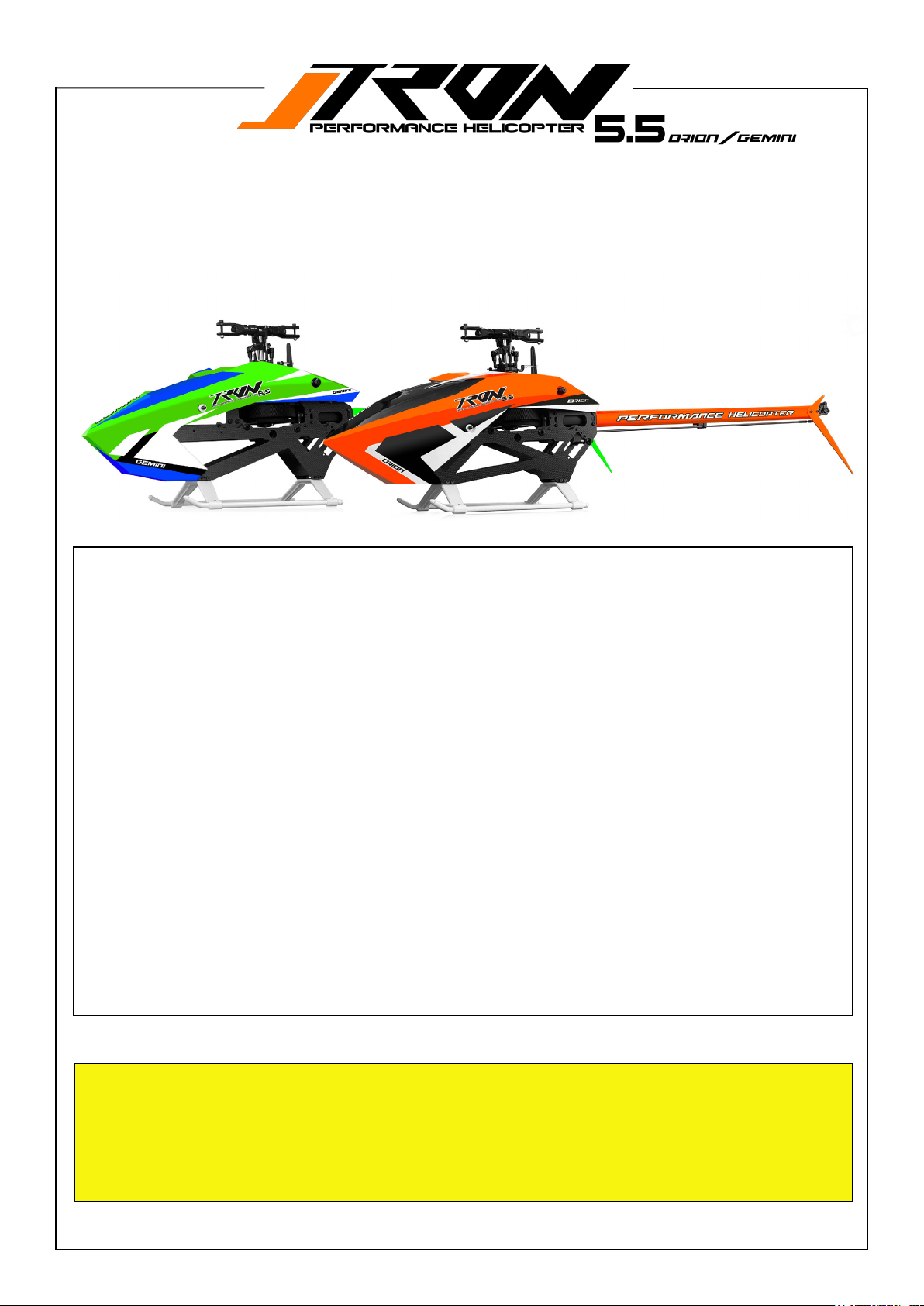
Features.
• Recommended main blade size 550mm. (550mm - 560mm possible). Tail blade size 86 - 98 mm.
• Supersonic canopy mounts included in kit. ( Backside )
• Fusioneditiondesignincludedinkit.(coloredboomandtailn)
• Wide battery compartment with quick lock and release system.
• Light,yetverystiandrobust.
• Dry weight= (1400) grams without blades and electronics.
• Full-size tail servo.
• Motor mounting features a bearing block supported pinion, reducing overall wear on the power
system and drive train.
• Compatible with a wide range of motor sizes. 4020, or 4025 series (1100KV-1200KV) recommended for 6s ( 6mm shaft diameter with min 15mm lenght required )
• 14T/6mm motor pinion included. (13,14,15,17T optional available)
• POM-CNCmachinedmaingear136T/whichprovidesveryecientoperation.
• Heavy duty one way bearing and hub design.
• Innovative FBL tray. ( Adjustable dampening hardness)
• Octa boom design with oval side shapes, no boom supports needed.
• Battery typical: 6S. ( 6S-4500mAh to 5500mAh.)
• Perfectly thought-out servo layout in conjunction with the FBL system and ESC.
• Easy cable routing with various options to ensure a clean setup. Modern, sporty and func
tional design.
• Highvisibilitycanopyforperfectorientationinight.2stylesavailable.OrionorGemini
Pre-assembled parts streamline the packing process with less waste and facilitate a quicker build.
This approach ensures assembling the helicopter is fast and straightforward. Additionally, it guarantees a high stan-
dard of quality control, ensuring all components t precisely without any unexpected issues or missing parts.
The provided drawings serve as references for part identication and clarication. Screws requiring checking or
loctiting are clearly labeled in the manual. Only remove these designated screws, apply Loctite 243 as instructed,
and securely tighten them back into place.
Page 5
About Tronhelicopters
Ricky Yin
Ricky is deeply involved in the manufacture, development and production of RC model helicopters
for a very long time. That goes back to the beginnings of Synergy Helicopters, which he took over
in 2010 after Stephen Fan passed away.
Dario Neuenschwander.
Dario has long been known in the RC helicopter scene. Dario can look back on a long career with
well-known manufacturers, where he was involved in the development and testing of products. To
name one, the MSH Protos Helicopters series and the development of the famous MSH Brain FBL
unit. Dario also did R@D work for SpinBlades where he is a longtime Factory Pilot. In 2017 Dario
tookabreakfromRCHelicopterstogetinvolvedinFPVracing.Hedidwellandtooktheocial
FPV-FAI world champion title in 2017.
Joachim Etter
Known for his business ideas and his ability to make products a success in combination with his
designs. Before that, he was closely associated with various manufacturers, for whom he did designs and business consultancy. Joachim was also the key founder, designer and builder of the
xnovamotors brand.
CAUTION:
This radio controlled helicopter is not a toy.
The product is not suitable for children under 14 years of age.
SAFETY PRECAUTIONS:
This kit includes some preassembled components. Please check for any
loose screws and tighten them before you proceed with assembly. Use loctite where required as
shown in this manual!
You are responsible for assembly, safe operation, maintenance, inspection and adjustment of the
model.
Before beginning assembly, please read these instructions thoroughly.
Checkallparts.Ifyoundanydefectiveormissingparts,contactyourlocaldealer.
For the USA market, The Academy of Model Aeronautics (AMA) is
a national organization representing modelers in the United States.
Please refer to the National Model Aircraft safety code from Academy of
Model Aeronautics.
Page 6
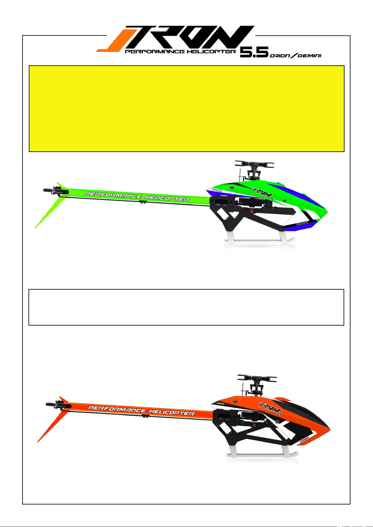
ORION AND GEMINI. What is the philosophy behind it and what are the dierences?
The two models are completely identical in terms of mechanics. The purpose is to provide you with a variety of style
choices.
Forthersttime,amanufacturerispresentingtheoptiontoselectfromtwodistinctdesignaesthetics.
TheOrionandGeminifeaturedierentstylesofcanopyanduniquelyshapedlowerframes.Youcaneasilyalteryourhelicopter‘sappearancebysimplyswappingthelowerframesandrepositioningthefrontcanopystand-omountstoteither
the Gemini or Orion canopy mount locations.
This feature allows for a fresh new look for your Tron 5.5 whenever desired.
Tron 5.5 GEMINI style
ThenewTron5.5GeminiandOrionstylesoerthelatestadvancementsinRChelicopterdesign,quality,andperformance.
Theysetnewstandardsforightcharacteristicsandprecisioninthetrue550class.Withunmatchedcustomizationoptions
andallpossibleupgradesincluded,thesemodelsdeliveranexceptionalyingexperience.
Experience the next level of RC helicopter design and performance!
Tron 5.5 ORION style
Page 7
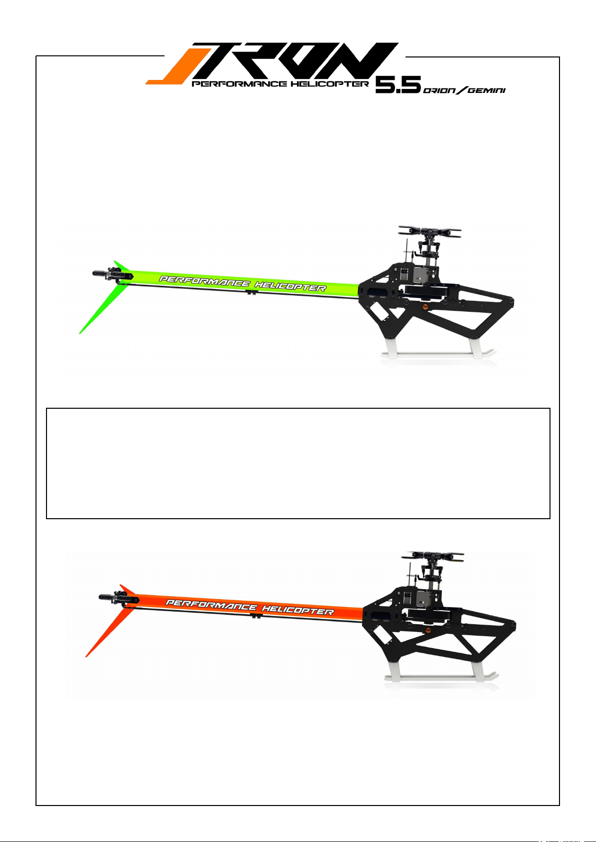
Tron 5.5 GEMINI style
Upgrades? No need!
• 2 high quality CNC battery trays included.
• 70 shore AND 90 shore head dampeners included.
• The innovative belt tensioner from Tron Helicopters is included.
• 2nd belt idler bearing system for tail box included which improves tail performance! ( can be also purchased seperately
for Tron 5.5/ Nitron90/Dnamic/Nitron 50)
• Color boom included
• Supersonic canopy qick release system included. (backside)
• Colortailnincuded.
Tron 5.5 ORION style
Page 8
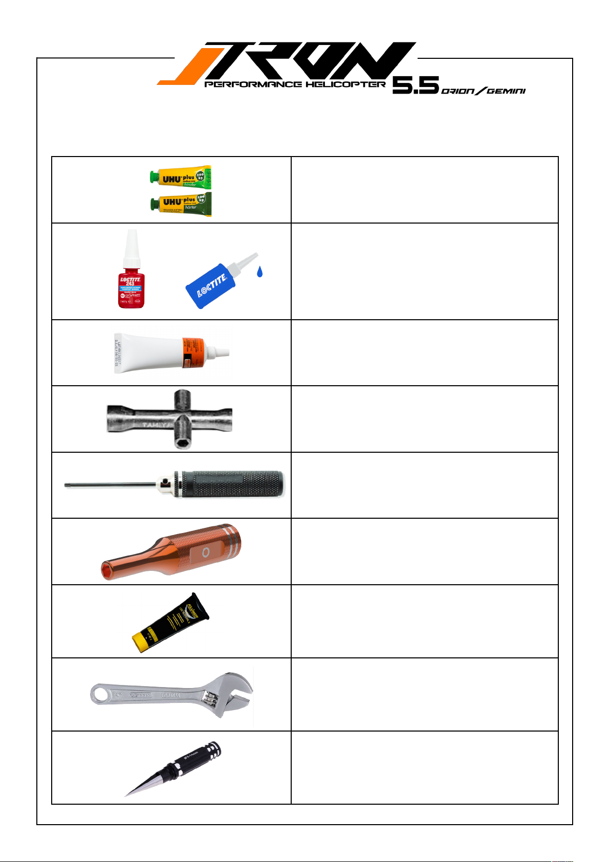
Tools required
2 component epoxy
=
Loctite 243 / medium strength
Grease
2* 5.5mm Wrenches for tail shaft nut
Hex screwdriver 1.5mm/2mm/2.5mm-
/3mm/4mm/5mm
TR501-518 Pair of customized nut wrench
for tail shaft assembly.
Optionally available at your Dealer.
SPRAG GREASE (SUCH AS ISOFLEX LDS18
Special A)
Adjustable Wrench
Canopy Reamer
Page 9
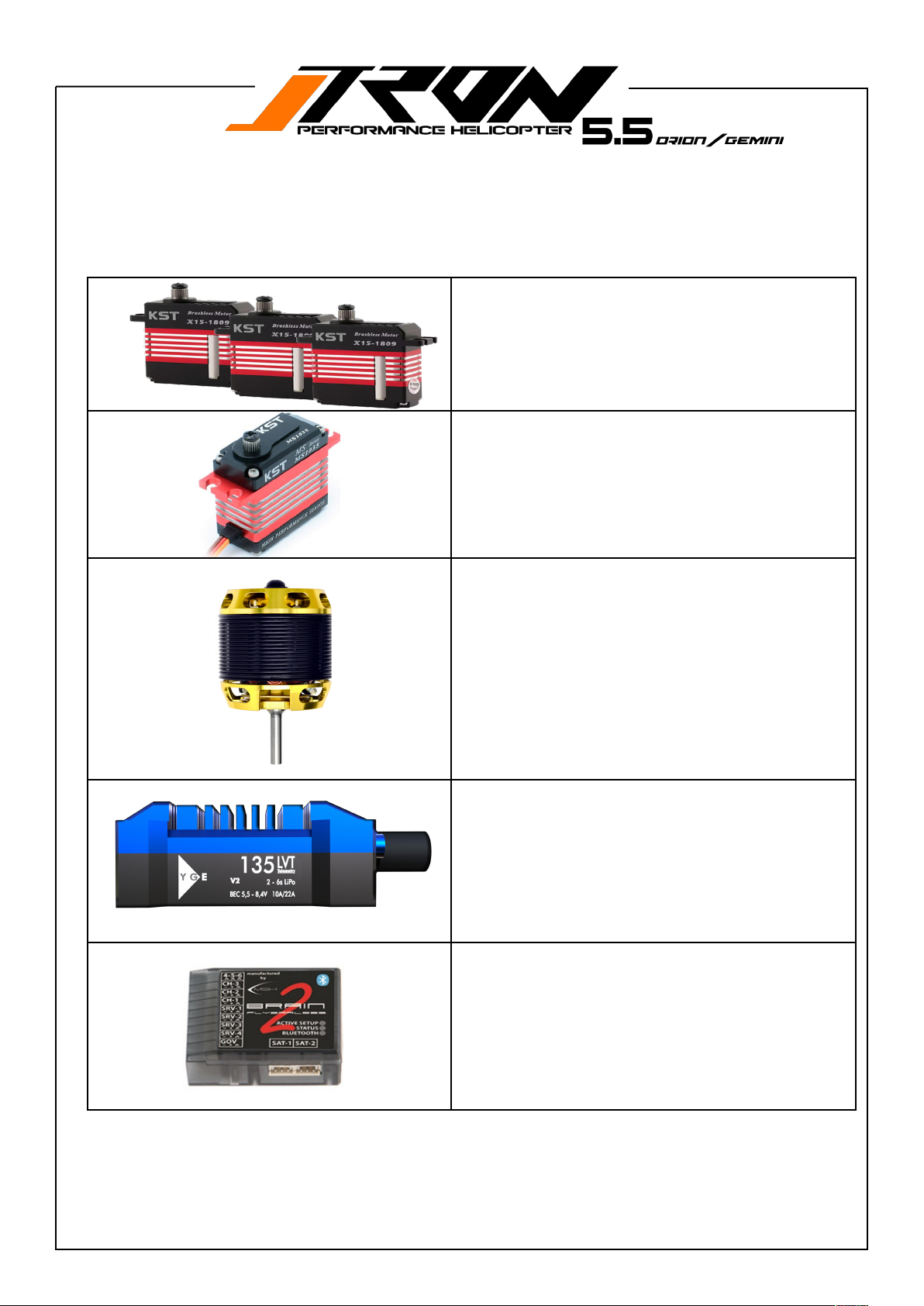
Electronics required
3*mini size servos for swashplate
1* mini or full size servo for tail
4020-4025 size motor (1100-1200kv)
80A-160A ESC (6S-8S)
FBL unit
Page 10
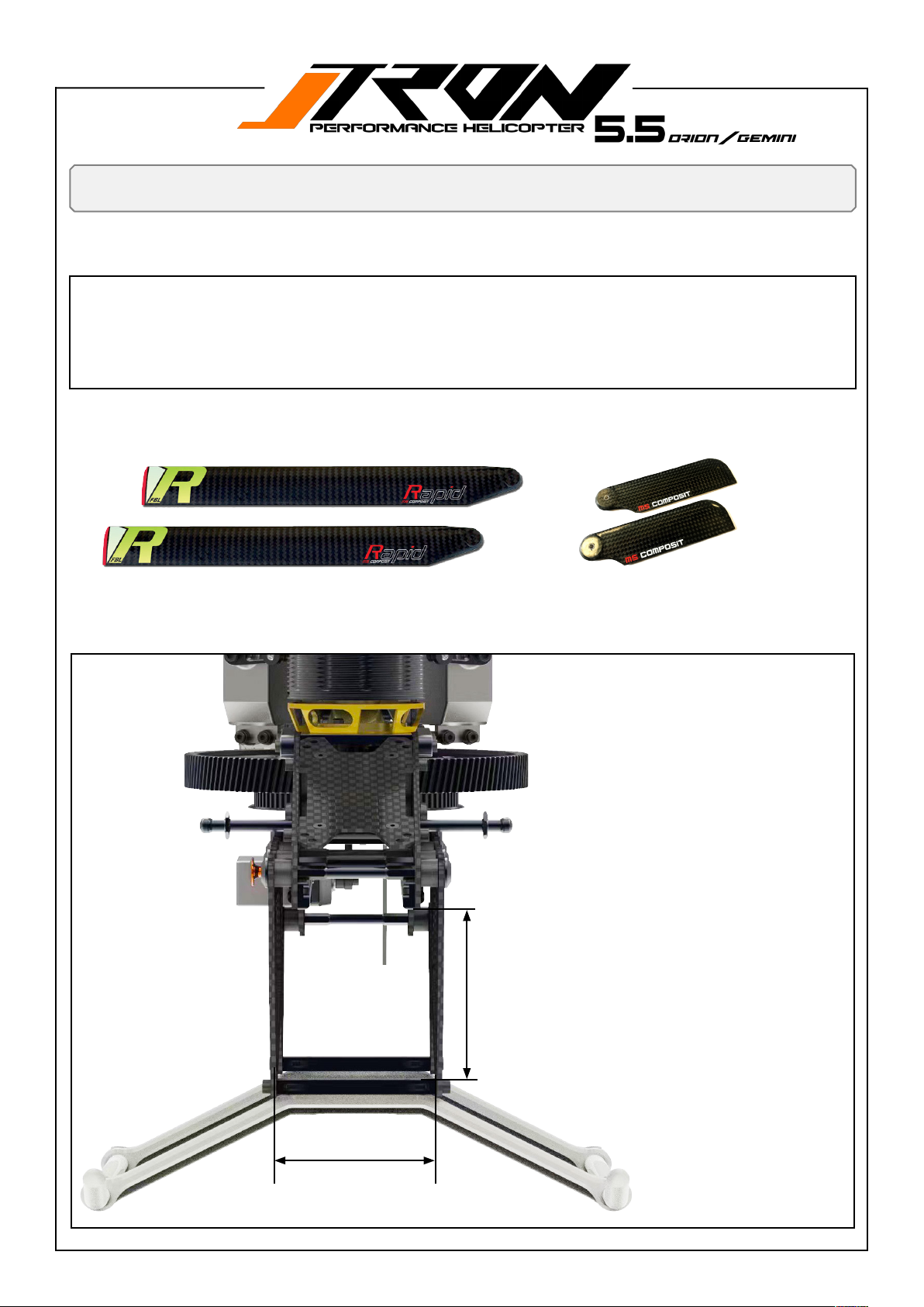
Information on equipment
Motor and ESC recommendation for Tron 5.5 ( 550- 560mm blade length )
• Motor: 4020-4025 size / 1100-1200kv for 6S /6mm shaft with 15mm min length. ( not included)
• Main gear tooth count 136T / Available motor pinion 13/14/15/16/17T ( 16T included in kit)
• ESC: 80-160A / 6-8S.
• Battery: 6S-4500-5600mah
• 3* mini type for cyclic servo and 1* mini or full size for tail servo
Main blade recommendation for Tron 5.5 (550mm-560mm length).
Tail blade recommendation for Tron 5.5 (85mm-97mm length).
56mm without
straps.
Battery compartment spacing:
height 64mm x width 56mm x
225mm length
( without straps! )
64mm without straps ( bottom to CNC battery tray )
Page 11
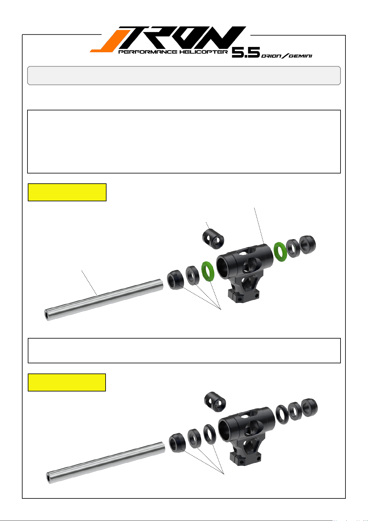
You will need:
Loctite 243 = blue
The center hub assembly has been pre-assembled at the factory.
Disassembly is not required if you use FIGURE 1 = medium as the default dampening conguration!
Thismakesbuildingthehelicopterquickandeasy.Youalsobenetfromahighlevelofqualitycontrol,ensuringthatallparts
ttogethercorrectly,withnounpleasantsurprisesormissingparts.
Thefollowingdrawingsareforreferenceandpartsclarication.Wehaveclearlyidentiedscrewsthatstillneedtobeche-
cked and/or loctited. Only remove screws labeled in the manual, apply Loctite 243, and screw them back in.
FIGURE 1 / MEDIUM
Stock conguration
TR550-011 Center Hub , 70 shore dampeners included.
TR503-204 Feathering shaft support.
Head assembly
TR502-103 Feathering shaft with Screws
TR550-011 Head dampeners 70 shore green, for Sport and moderate
3Dying.(default)
If you prefer to use FIGURE 2, please exchange the green O-rings (70 shore) with the black O-rings (90 shore), which are also
included in the kit.
FIGURE 2 / HARD
For hard 3D ying
TR550-011Headdampeners90shoreforhighrpmandhard3Dying
style.
Page 12
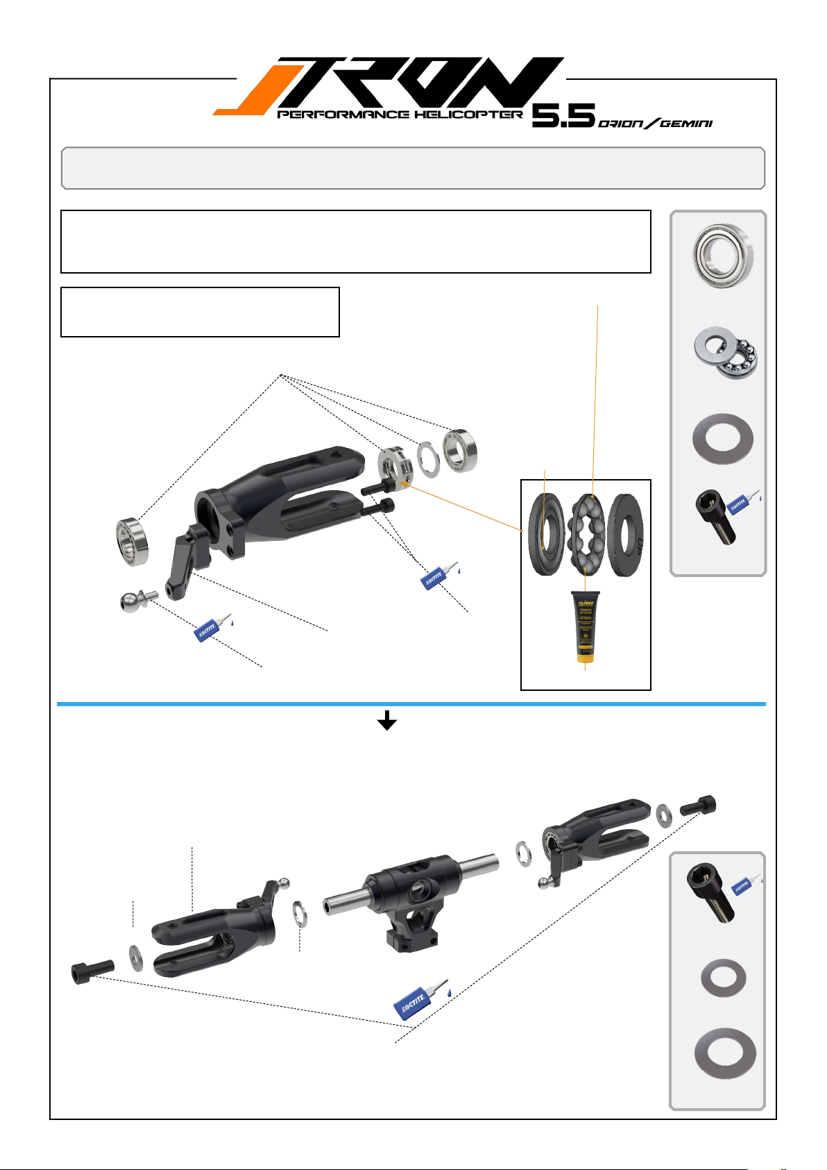
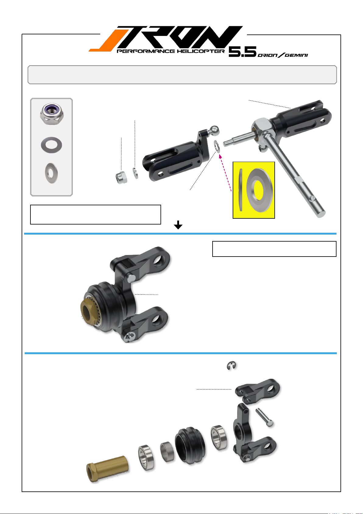
You will need:
Loctite 243 = blue
1. Remove the bearings to apply grease to the thrust bearings.
2. Reassemble them in the order shown in the render below.
3. Assemble the main grip arms and apply Loctite 243 to screws labeled as D.
4. Assemble the pivot balls and apply Loctite 243.
Main blade grip assembly
A
The blade grip have been pre-assembled at the
Pay attention to the orientation of the ball cage.
factory. Disassembly is required to apply grease
to the thrust bearings.
TR550-805 Main grip bearings set, with thrust bearings and shims.
C
B
D
A
TR580-003 Main grip arms.
TR550-110 Pivot steel ball set
for head.
D
M2.5x8mm Hex-Socket-screw
A
Internal hole bigger.
Apply grease.
4*Radial Bearing
8x14x4mm
B
2*Thrust Bearing
8x14x4
C
2*shim 18*8*0.5
D
4*M2.5x8mm Hex-So-
cket-screw
TR550-012 Main blade grip including bearings.
Shim 12x5x2mm
B
C
A
Shim 12x8x1mm
M5*12mm Hex-Socket-
screw
C
A
B
A
2*M5x12mm Hex-So-
cket-screw
C
2*shim 12x5x2mm
B
2*shim 12x8x1mm
Page 13
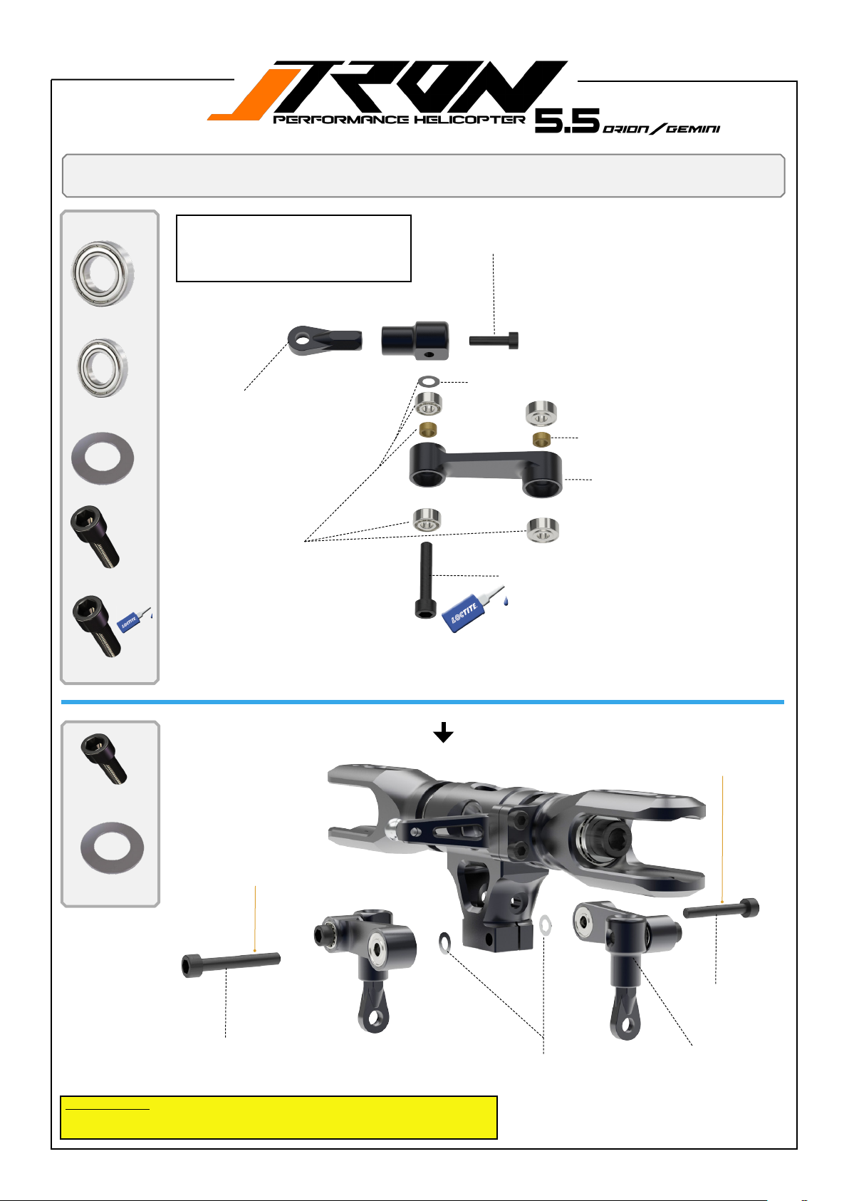
You will need:
Loctite 243 = blue
Head assembly
A
4*Radial Bearing
3x8x3mm
B
4*Radial Bearing
3x7x3mm
C
2*shim 3x5x0.15mm
D
2*M2.5x8mm Hex-So-
cket-screw
E
2*M3x16mm Hex-So-
cket-screw
The anti-rotation arms have been preassembled at the factory. Disassembly
is not required! Only remove screw E,
apply Loctite 243, and screw it back in.
TR504-100 Plastic ball link
set 2,5mm
TR550-103 Bearing set and
spacers for anti rotation arms.
M2.5x8mm Hex-Socket-
C
Shim 3x5x0.15mm
B
B
E
screw
D
A
Shim 3x2mm
TR550-105 Anti rotation arm set
with bearings,shims,screws and
ball links.
A
M3x16mm Hex-Socket-screw
A
2*M3x20mm Hex-So-
cket-screw
B
Shim 3x5x0.15mm
Do not tighten now!
B
A
M3x20mm Hex-Socket-screw
Important note!
Do not tighten the M3*20mm screws here. Apply Loctite 243 and tighten them after
assembling the main shaft to the center hub.
B
Shim 3x5x0.15mm
Do not tighten now!
A
M3x20mm Hex-So-
cket-screw
TR550-105 Anti rotation arm set
with bearings,shims,scews and
ball links.
Page 14
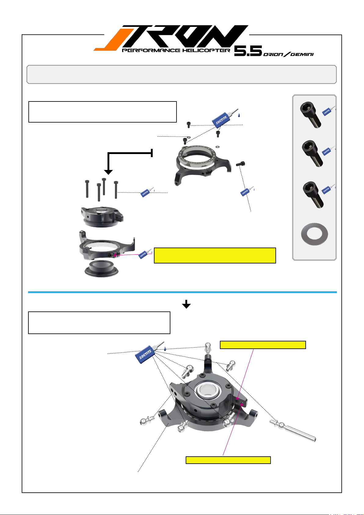
You will need:
Loctite 243 = blue
Swashplate is preassembled at the factory.
Disassembling is not required.
Only remove screws add Lotide 243 and screw back in.
Shim 2x5x0.5mm
Head assembly
B
D
B
B
D
M2*4mm Hex-So-
cket-screw
A
1*M2.5x8mm Hex-So-
cket-screw
C
C
C
C
Swashplate is preassembled at the factory.
Disassembling is not required.
Please use loctite 243 on all pivot ball threads.
A
M2x14mm Hex-Socket-screw
M2.5x8mm Hex-Socket-screw
Please tighten screw A with minimal force
only! please use loctite 243!
B
3*M2x4mm Hex-Socket-
screw
C
4*M2x14mm Hex-Socket-
screw
D
2*shim 2x5x0.5mm
TR580-110 Pivot steel ball set
for head. (16pcs.)
TR550-108 Complete swashplate assembly. (included pivot ball)
Inner thread for precise ying style.
Outer thread for agile ying style.
Page 15
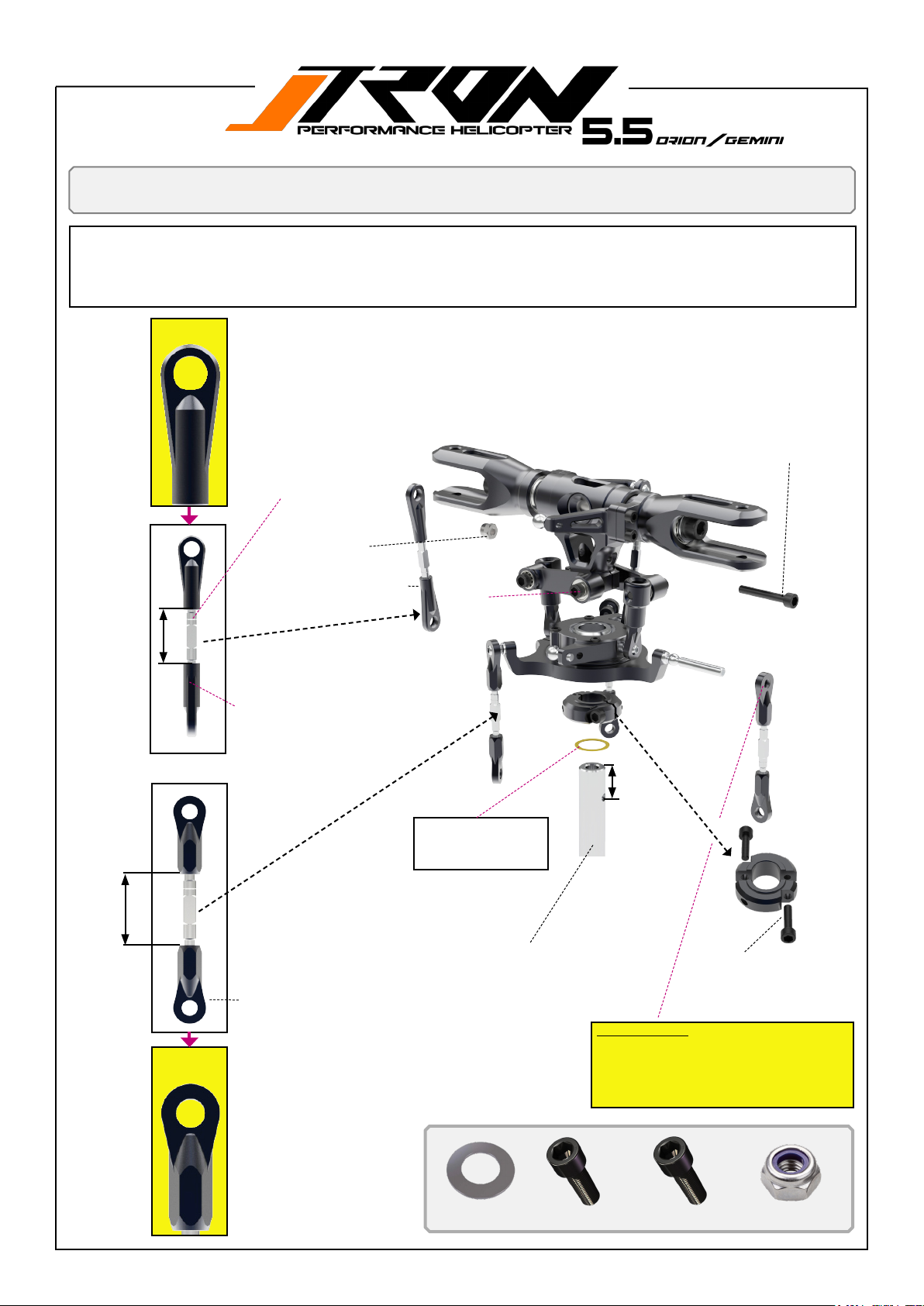
You will need:
Head assembly
Loctite 243 = blue
1. Insertmainshaftintocenterhubrst.
2. Tighten screw B to lock nut D.
3. Tighten the screws A =M3x20mm which are shown on page 13 left and right step by step (use loctite 248).Make sure the
shim A do not fall out.
Swashplate to
main grip.
Groove indicates CCW
thread!
TR502-230 Linkage rod set. Contains 3* rod for linkage of swashplate servo or
swasplate to main grip. (Rod for servos to swashplate and swashplate to grip
arms are identical)
M3x20mm Hex-Socket-screw
(15mm)
(19mm)
Servo to
swashplate
1* Lock nut M3
TR704-100 Plastic ball link
2* Linkage rod, swashplate to main grip.
CW thread!
Kepp shim E in a save
place! You will need it
3* Linkage rod, servo horns to
swashplate.
TR582-104 Hollow main shaft
TR504-100 Plastic ball link
set 2,5mm
D
A
at page 44
B
E
12mm
C
C
Do not tighten yet!
2*M3x12mm HexSocket-screw
Important note!
The ball links have a larger and a smaller
diameter. Always make sure the larger diameter is pointing towards the pivot ball when
assembling!
E
1* Shim 1x10x0.3mm
A
1*M3x20mm Hex-Socket-screw
B
2*M3x12mm Hex-Socket-screw
D
1* Lock nut M3
Page 16
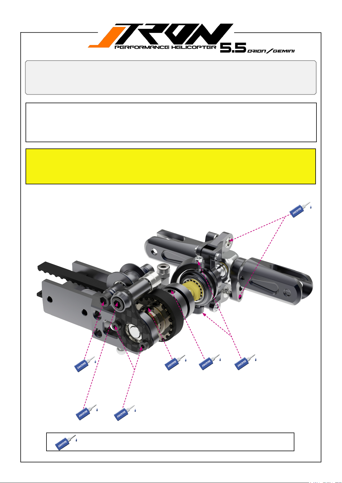
You will need:
Loctite 243 = blue
The tail housing assembly have been pre-assembled at the factory.
Removal of screws to add locktite is necessary!
Thismakesthehelicopterbuildveryquickandeasy.Youalsobenetfromahighlevelofqualitycontrolasweensureall
partsttogethercorrectly,eliminatingunpleasantsurprisesandmissingparts.
The tail thrust bearings have been greased by the factory! If you are building a new kit, it is not necessary to remove
the tail blade holders to add grease to the thrust bearings!
Pay attention to the two M2.5x8mm (A) screws that hold the tail pitch arm support, as shown on page 17. These
screws need to be loctited as well!
Tail assembly
=Remove screw, add locktite and screw it back in
Page 17
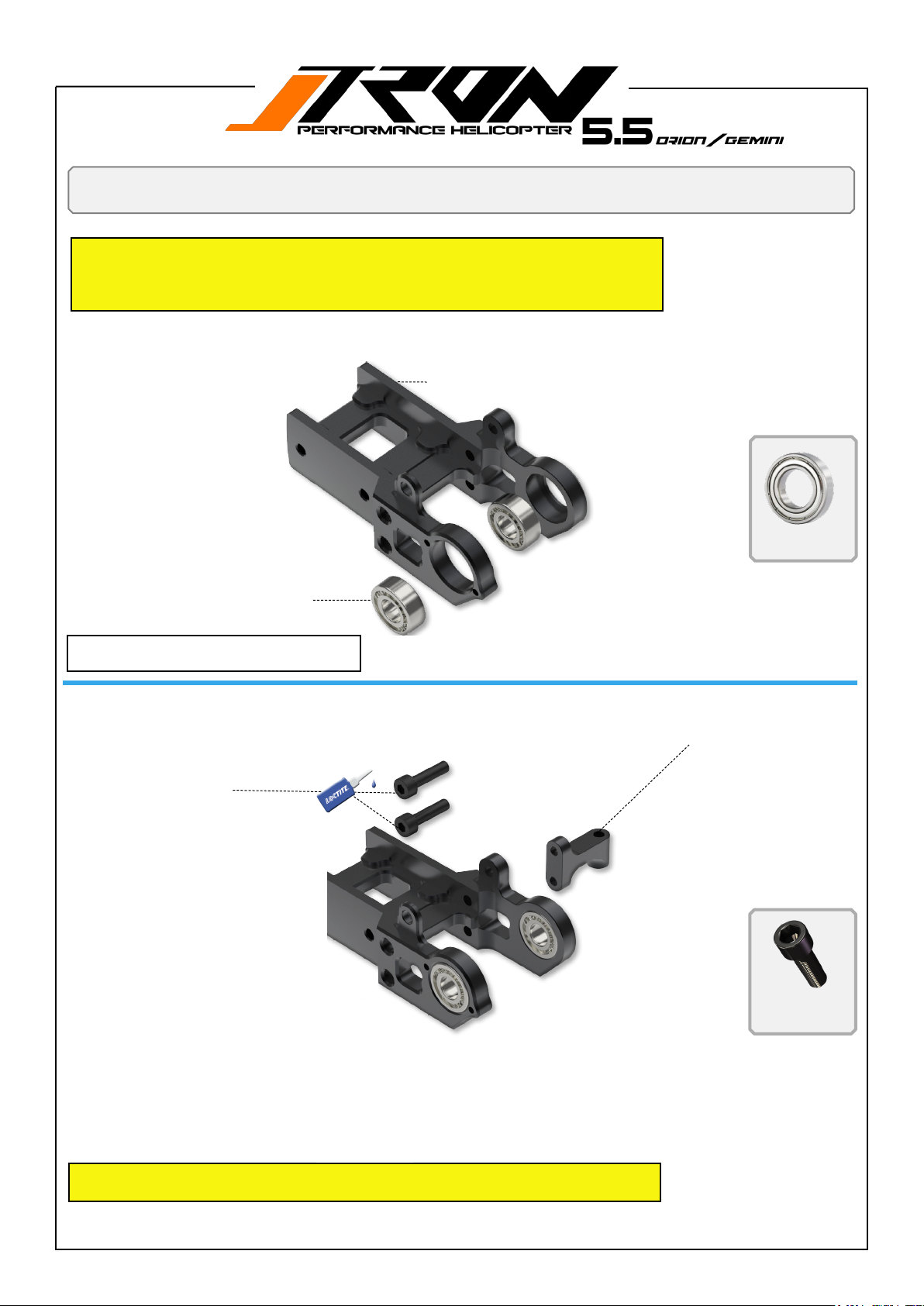
You will need:
Loctite 243 = blue
1. The following drawings showing the tail drive housing are for reverence and parts
clarication.
2. Keep in mind that when purchasing spare parts separately, you should add Loctite
where specied!
TR550-403 Tail case assembly including
bearings.
TR506-511 Tail case bearings
Tail assembly
2*Radial Bearing
5x11x4mm
The tail case bearings ar assembled at the
factory. Disassembly is not required.
M2.5x8mm Hex-Socket-screw
TR501-408 Tail pitch arm support
A
A
A
2*M2.5x8mm Hex-So-
cket-screw
Keep in mind that when purchasing spare parts separately, you should add Loctite
where specied!
Page 18
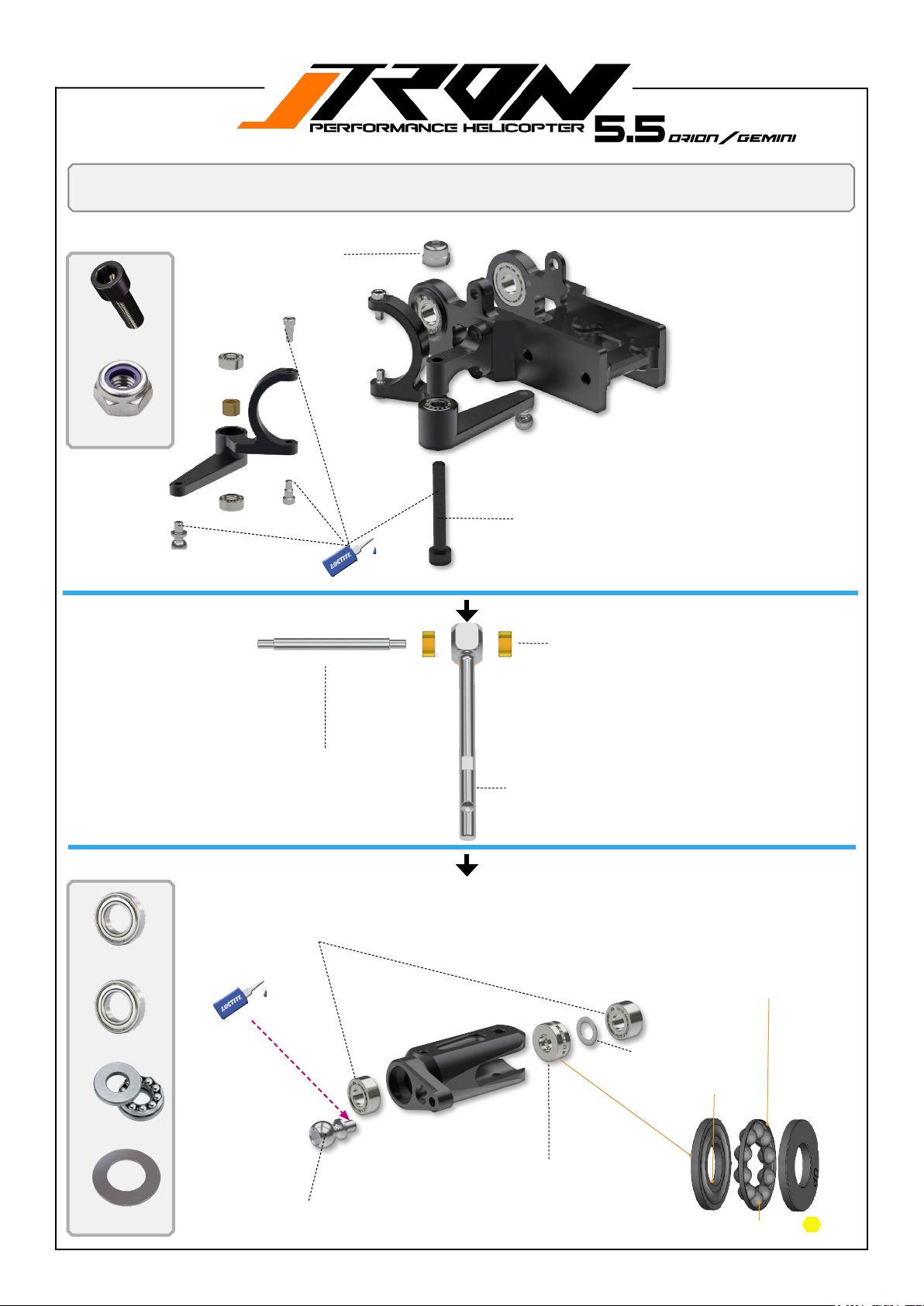
You will need:
Loctite 243 = blue
Tail assembly
1* Lock nut M3
A
1*M3x22mm Hex-So-
cket-screw
B
1* Lock nut M31* Lock nut M3
Tail pitch arm assembly TR550-316
B
M3x22mm Hex-Socket-screw
A
TR504-404 Tailshaft dampening set.
A
2*Radial Bearing
4x8x4mm
B
2*Radial Bearing
4x9x4mm
C
2*Thrust Bearing
4x9x4
D
2*shim 4x8x0.3mm
TR502-324 Tail blade holder spindle.
TR550-401 Tail blade holder
bearing set.
A
TR550-110 Pivot steel ball set for
head. (16pcs.)
TR582-407 Tail shaft with dampeners.
C
D
TR506-491 Tail blade holder thrust
bearing set.
Pay attention to the orientation
B
of the ball cage.
Shim 4x8x0.3mm
Internal hole bigger.
Apply grease.
Page 19
You will need:
Loctite 243 = blue
A
2* Lock nut M3
Tail assembly
TR550-525 Tail blade holder set
complete.
Shim 6x3x0.8mm
Lock nut M3
B
2*shim 6x3x0.8mm
A
C
2*customized shim
Wrench size for nut B = 5.5mm.Outer diameter should
not exceed 9.2mm and min. 20mm length required.
Optional ( TR:501518 )
B
C
TR588-004 customized shim
Pay attention to the correct
orentation of the shim!
The tail pitch slider is assembled at the factory.
Disassembly is not required.
TR550-428 Tail pitch slider assembly.
(complete)
TR550-322 Tail pitch linkage with c-clips
and shafts.
Page 20
You will need:
Loctite 243 = blue
TR501-319 Tail pulley 19T (default) ratio 4.21
TR501-318 Tail pulley 18T (optional) ratio 4.44
TR501-320 Tail pulley 20T (optional) ratio 4.00
Tail assembly
C
1*shim 5x8x0.15mm
M4x4 mm set screw
Do not screw them in yet
A
2*M4x4mm set screw
A
C
Shim
5x8x0.15mm
1. Insert the tail shaft (step 1) into the tail pitch slider (step 2). Ensure the pulley aligns with the pitch pins (step 3) then
slide the tail shaft into the tail housing bearings, tail shaft collar, tail pulley, and the shim (12x8x0.5 / C) Step 4.
2. Align the at spot on the tail shaft with the set screws.
3. Slightly tighten the 2 set screws (A-B) on the pinion and collar. DO NOT APPLY LOCTITE TO THEM IN THIS STEP.
REFER TO PAGE 22!
B
M4x5 mm set screw. Do not screw
them in yet
TR501-306 Tail shaft collar
B
2*M4x5mm set screw
A
Step 4
Step 3
B
Step 2
Step 1
Page 21
You will need:
Loctite 243 = blue
1. Attach the tail slider pitch links to the tail blade grip pivot balls. Refer to the render below for the correct order.
2. Assemble the carbon tail idler plate (Figure 1).
3. Add tail belt.
Add the tail belt before assembling
the belt idler bearing (see page 22).
Tail assembly
A
A
TR550-406 Mounting brackets Belt pusher / complete assembly
This tail performance upgrade can be used
for Tron 5.5 V1 / Nitron 50 and 90 / Tron 5.8
and Tron 7.0 DNAMIC
TR504-550 Tail belt
Figure 1
M2.5x6mm Hex-Socket-screw
A
2*M2.5x6mm Hex-So-
cket-screw
Page 22
You will need:
Loctite 243 = blue
Tail assembly
E
2*Radial Bearing
3x8x3mm
D
D
1*M3x28mm Hex-So-
cket-screw
A
C
B
C
1*M3x8mm Hex-Socket-
screw
E
E
B
2*Radial Bearing
3x7x3mm
B
A
1*M3x10mm Hex-So-
cket-screw
The collar design is to remove tail shaft lateral play.
1. After tighten the pulley set screw A ,slightly push the collar to the right while pushing the tail shaft to the left side.
2. Then tighten the set screw B on the collar.
Important note!
Screw C, M3*8mm, can be used to adjust the play
for the bearing belt space. Leave approximately
0.1mm of play after the belt is under tension.
A
B
Tech tip!
Payattentiontotheorientationoftheatspotsonthetailshaft
when tightening the set screws. Use a minimal amount of Loctite
243 for the set screws.
Page 23
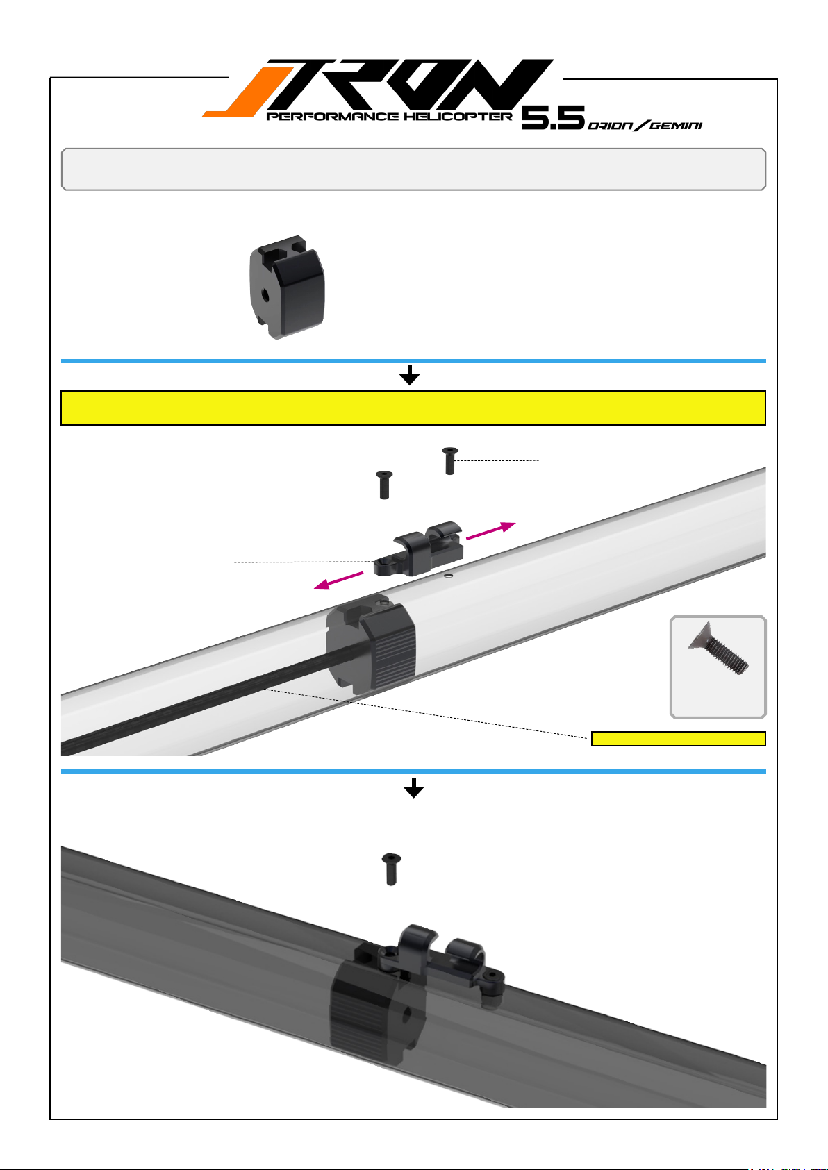
Boom assembly
TR504-501 New tail pushrod assembly tool for T5.5/5.8/Nitron
Insert the tail push rod with the nuts facing up into the boom. Ensure that when you tighten the screws for the tail push rod guide, your
mounting device faces up as shown in the illustration.
TR503-217 Tail pushrod
guide. Included screw and nut
FRONT
A
2*M2.5*8mm Hex-Socket-screw
A
TAIL ROTOR
A
2*M2.5x8mm Hex-So-
cket-screw
Use the tail pushrod temporary.
-Tail Boom Orange TR501-657/ default for ORION
-Tail Boom Yellow TR501-658
A
-Tail Boom Pink TR501-659
-Tail Boom Green TR501-660 /default for GEMINI
-Tail Boom BlackTR501-656
Page 24
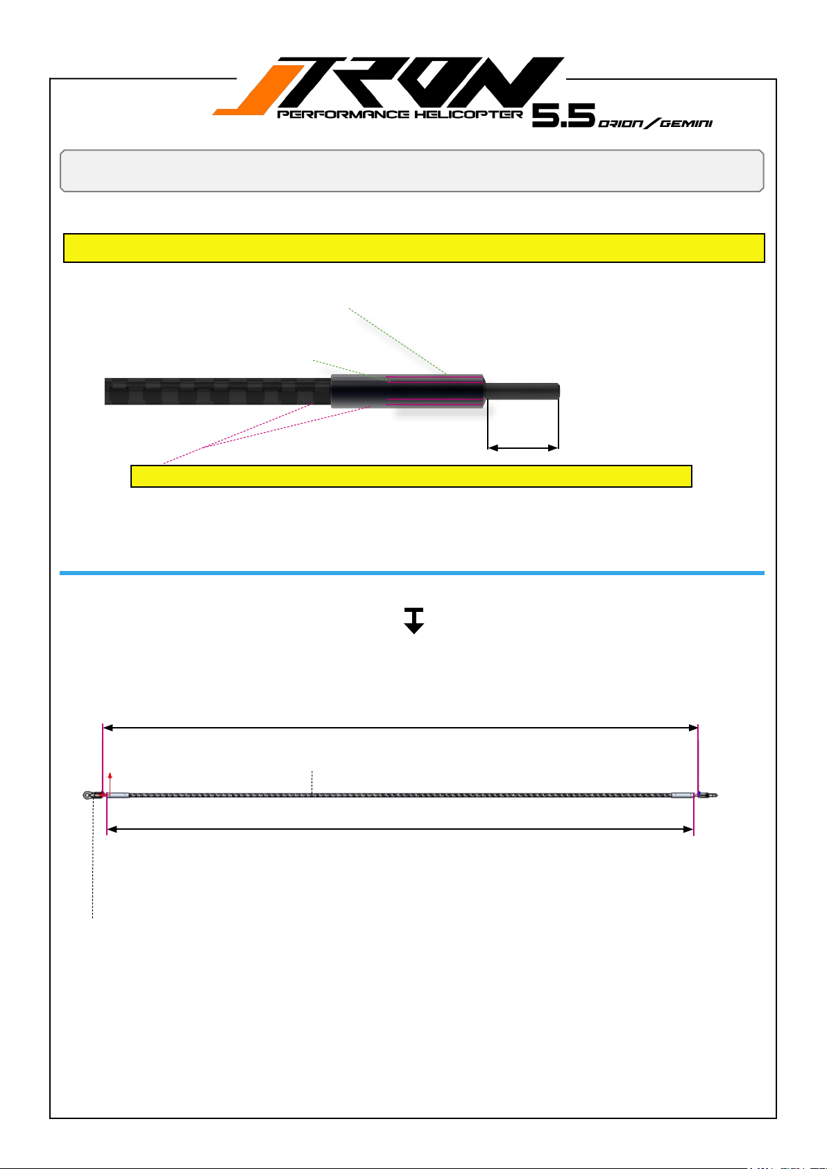
You will need:
2 component epoxy
Tail assembly
Apply a two-component epoxy to glue the thread into the tail push rod and the shell on the outside of the rod. This double safety measure ensures that the thread cannot turn if you adjust the ball-link after the assembly has fully hardened.
Apply 2 component epoxy on the outside of the carbon rod.
Apply a two-component epoxy inside the hole of the carbon rod to secure the threaded rod to the carbon rod.
Ensure that the assembly remains stationary while drying. Secure it on both sides to prevent any movement.
12mm on both sides.
Use 2 component epoxy!
12mm
TR504-100 Plastic ball link set 2,5mm
(593mm)
TR550-513 Tail pushrod assembly
(583mm)
Page 25
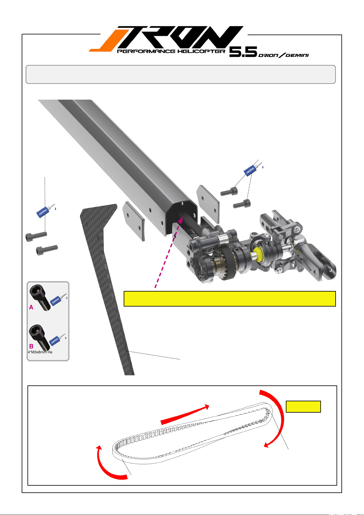
You will need:
Loctite 243 = blue
Front (main frame side)
2*M3x10mm Hex-Socket-Screw
A
A
Tail assembly
2*M3x8mm Hex-Socket-Screw
B
B
Insert the tail belt through the tail boom until it comes out the other end. Make
sure it is twisted as shown below. For reference, follow the image below.
A
2*M3x10mm Hex-So-
cket-Screw
B
4*M3x8mm Hex-Socket-
Screw
Ensure to have your tail belt oriented as shown in the illustration
Back (tail rotor side)
-Tail Fin Orange TR505-421/ default for ORION
-Tail Fin Yellow TR505-422
-Tail Fin Pink TR505-423
-Tail Fin Green TR505-424 / default for GEMINI
Figure 1
Back (tail rotor side)
Front (main frame side)
Page 26
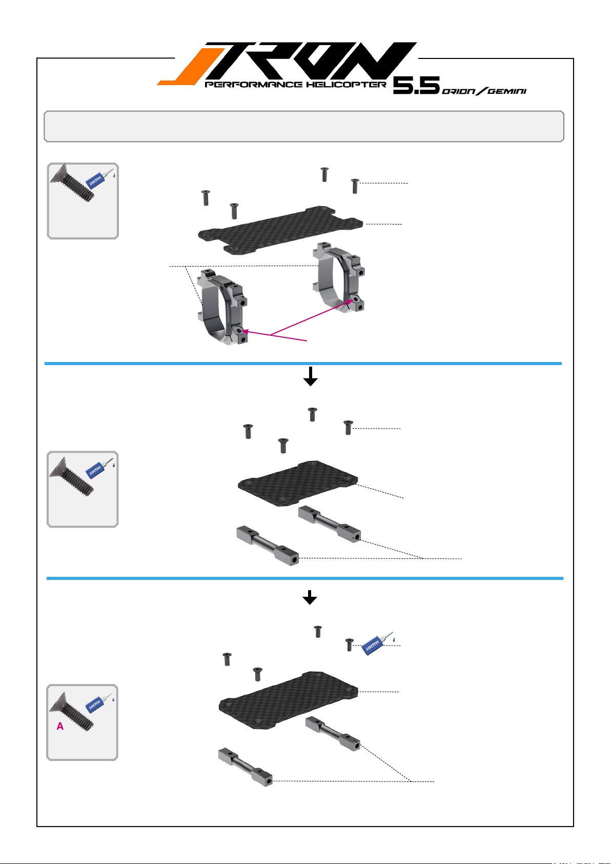
You will need:
Locktite 243 = blue
Upper main frame assembly
A
4*M2.5x6mm Hex-So-
cket-screw
TR501-512 Tail boom clamp
set
A
A
4*M2.5x6mm Hex-Socket-screw
A
A
TR585-211 Radio mounting tray
Pay attention to the correct orientation!
A
A
A
A
4*M2.5x6mm Hex-Socket-screw
A
4*M2.5x6mm Hex-So-
cket-screw
A
4*M2.5x6mm Hex-So-
cket-screw
GYRO CF Plate TR505-212
Tray mounting spacers
TR501-200
A
A
4*M2.5x6mm Hex-Socket-screw
A
A
ESC carbon tray TR505-215
Tray mounting spacers TR501-200
Page 27
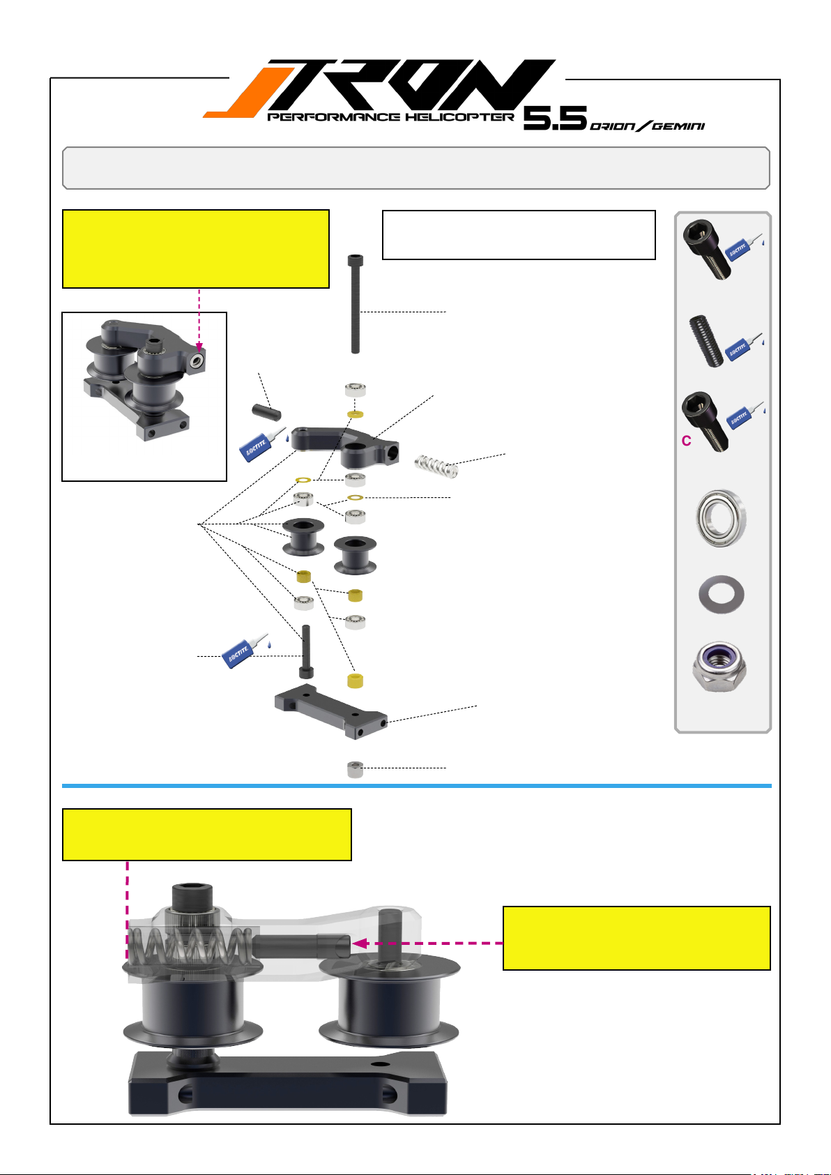
You will need:
Locktite 243 = blue
Belt tensioner and battery lock assembly
Tech tip!
Ensure the spring is aligned with the idler
arm during assembly. After the boom and
belt are in place, tighten the set screw by (3)
turns. Refer to page 51 for reference!
1*M4x8mm set screw
B
TR550-408 Belt tensioner assembly complete
E
TR550-240 Tron belt tensioner arm assembly
D
C
1*M3x16mm Hex panhead
screw
The belt tensioner is preassembled at the factory. Disassembly is not required.
A
Please add loctite 243 on screws B and C only
A
1*M3x30mm Hex-So-
cket-screw
1*M3x30mm Hex-Socket-screw
B
1*M4x8mm set screw
D
TR550-240 Tail idler pulley
mounting plate assembly
TR702-810 Spare spring for
belt tensioner
D
D
2*shim 8*0.5mm
E
C
1*M3x16mm Hex
panhead screw
D
D
6*Radial Bearing
3x7x3mm
E
D
2*shim 3x5x0.15mm
F
TR550-406 Mounting breackets
belt tesnioner
1* M3 lock nut
Tech tip!
Ensure the spring is aligned with the idler arm
during the assembly of the helicopter.
F
1* M3 lock nut
Adjust the set screw to load the belt tensioner by (3) full turns after the entire tail boom
has been assembled to the main frame.
Refer to page 51 for reference!
TR550-408 Belt tensioner assembly complete
Page 28
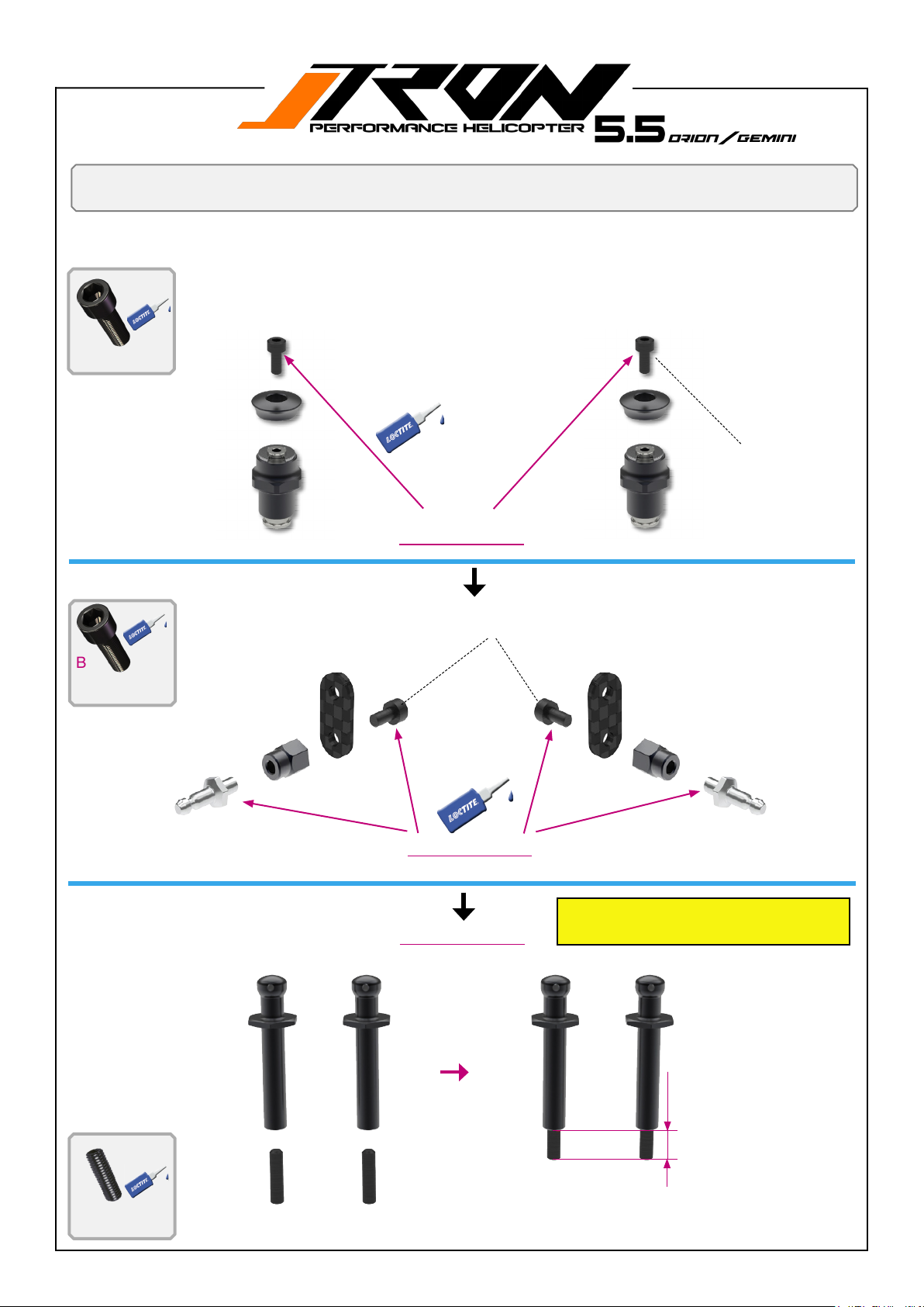
You will need:
Loctite 243 = blue
A
2*M2.5x6mm Hex-So-
cket-screw
Upper main frame assembly
TR505-245 Back Supersonic canopy
mounts
A
A
M2.5x6mm Hex-Socket-screw
!
Apply loctite !
M3x6mm Hex-Socket-screw
B
2*M3x6mm Hex pan-
head screw
B
Apply loctite !
Apply loctite !
B
Gemini and Orion style front ca-
nopy stando posts.
TR561-123 NiTronFront
8mm
canopy mounts
A
2*M3x12mm set
screw
A
A
Page 29
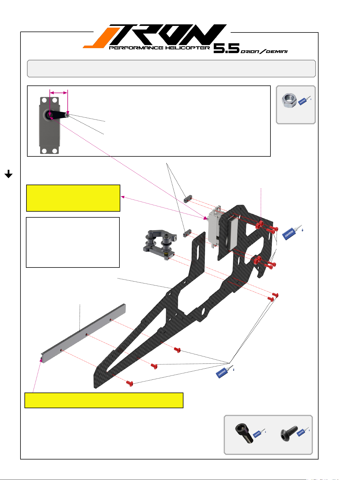
You will need:
Loctite 243 = blue
(15-16mm)
1. Servo horn position at 90 degree and ball link length for ELEVATOR SERVO.
2. Please note: The length of the servo horn ball link may vary slightly depending on
theservomanufacturerandtheybarmanufacturerbrand.
1* Nut M2
TR550-112 Pivot steel ball set for servo horns
Tech tip!
Pay attention to the orientation of the servo
horn arm and the position of the spline
when assembling to the frame!
1. Keep the belt tensioner spring
ush with the pulley arm.
2. Use set screw M3*16mm for
adjusting.
3. Preload spring after assembling
the boom and belt to the main
gear by ( 3 ) full turns. Page 46,
step 7
Upper left frame assembly Orion/Gemini
1* Nut M2 for secure
pivot steel bal
TR501-122 Servo mount plates (midi size servos)
TR501-102 Black
anodized washers /
2.5mm x 8
A
M2.5x8mm Hex-Socket-
screw
A
TR505-202 Upper left frame mini servo
TR503-215 Rail guide for battery tray
B
!
Note the orientation of the rail, which is facing towards the inside
and the guide rail is facing up.
B
B
B
B
M3x6mm Hex-Socket-screw
A
4*M2.5x8mm Hex-So-
cket-screw
B
5*M3x6mm Hex pan-
head screw
Page 30
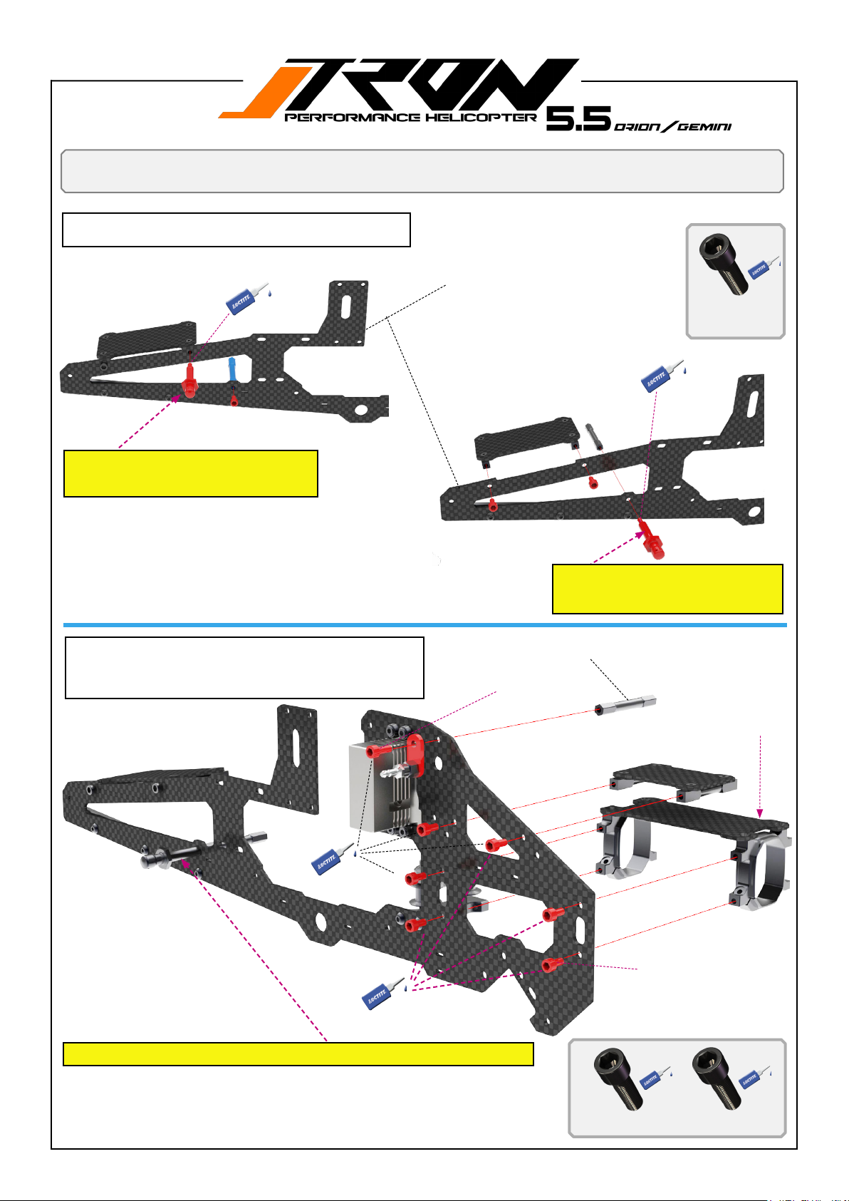
You will need:
Loctite 243
1. Assemble ESC tray to upper main frame.
2. Assemble canopy stando to upper main frame.
Upper left frame assembly Orion/Gemini
A
A
GEMINI style canopy stando
position! (see page 27)
1. Assemble boom clamps with tray to upper main frame
2. Assemble gyro mount tray to main frame
3. Assemble canopy support with spacer to upper main
frame.
TR505-202 Upper left frame mini servo
A
A
ORION style canopy stand-
o position! (see page 27)
TR501-219 Frame spacers
1*M3x8mm Hex-Socket-screw
A
2*M3x6mm Hex-Socket-
screw
B
A
TR505-212 Gyro CF Plate
A
A
A
Render does show ORION style canopy stando position.
TR585-211 Radio mounting tray
A
A
6*M3x6mm Hex-Socketscrew
6* M3x6mm Hex-Socket-
A
screw
B
1*M3x8mm Hex-Socketscrew
Page 31
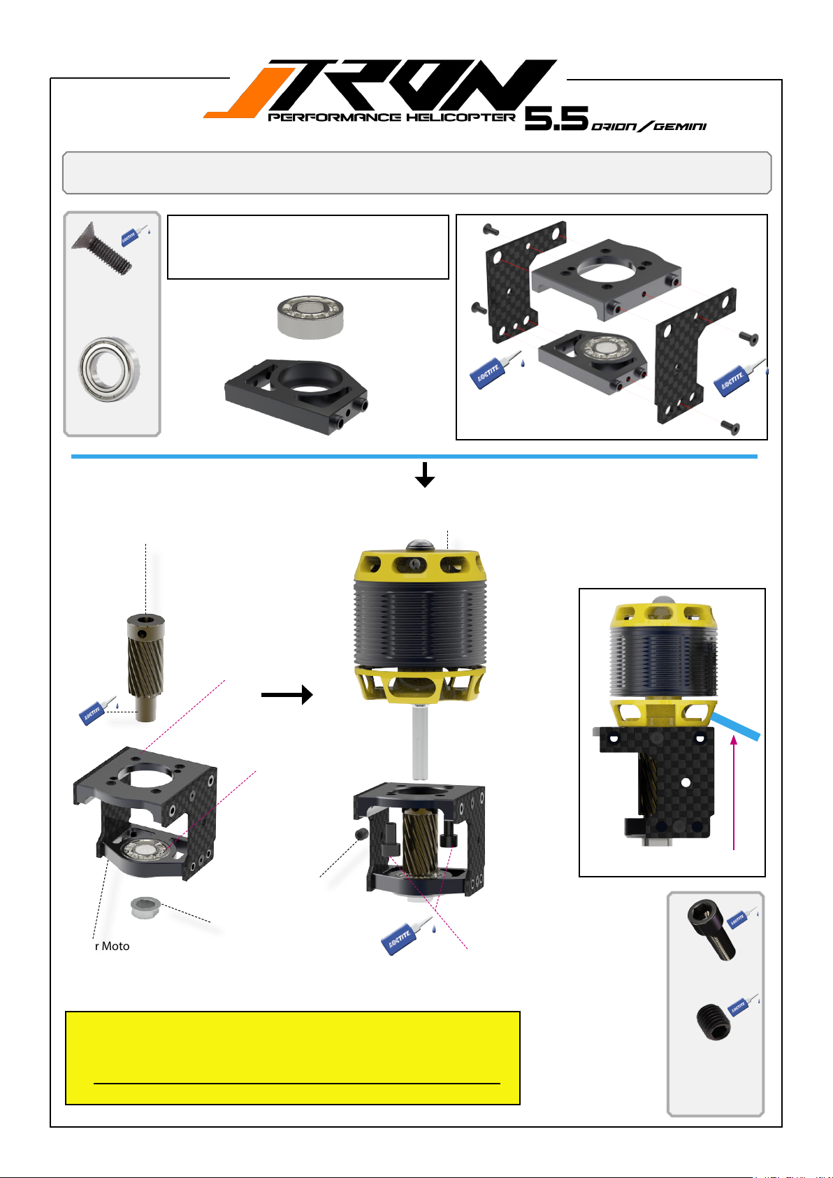
You will need:
Loctite 243 = blue
Motor mount and pinion
Motormount is preassembled at the factory.
Disassembling is not required.
Just remove 4* M 2.5x6 screws, add loctite 243
and screw it back in.
A
4*M2.5x6mm Hex-So-
cket-screw
B
1*Radial Bearing
8x19x6mm
TR582-016 Motor Pinion 16T 6mm
(included in kit)
A
B
BL motor 4020-4025 size 1100-1200kv
(not included)
A
A
A
Upper Motor mount
TR550-208
min. 15mm motor-
Motor mount Support
plates TR550-210
A
B
M4x4mm set screw
Locking nut for motor pinion
Lower Motor mount TR550-209
shaft length required.
B
M4x8mm set screw
Available pinions for Tron 5.5 Orion / Gemini
• 13T/6mm TR582-013 / included lock nut 10.46 ratio
• 14T/6mm TR582-014 / included lock nut 9.71 ratio
• 15T/6mm TR582-015 / included lock nut 9.06 ratio
• 16T/6mm TR582-016 ( default, included in kit ) 8.50 ratio
• 17T/6mm TR582-017 / included lock nut 8.00 ratio
Motor cable direction.
B
2*M4x8mm Hex-Socket-
screw
A
1*M4x5mm set screw
!
Page 32
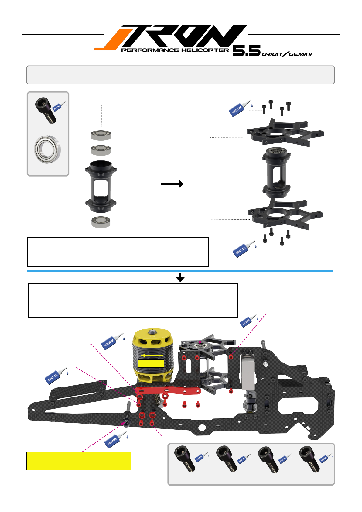
You will need:
Loctite 243 = blue
Upper left frame assembly Orion/Gemini
TR506-105 Main shaft bearing set
4*M2.5x6mm Hex-Socket-screw
A
8*M2.5x6mm Hex-So-
cket-screw
B
TR501-205 Servo mount unit
B
B
4*Radial Bearing
10x19x5mm
TR501-206 Main shaft
support with bearings.
TR501-205 Servo mount unit
B
The mainshaft support tube has been assembled at the factory. Disassembly is not required, and no Loctite is needed to secure the bearings.
If the bearings need to be replaced, you may want to use a hair dryer to
slightly heat up the support tube.
A
A
4*M2.5x6mm Hex-Socket-screw
1. Assemble motor mount with motor support stiener to the main frame. Do not
tighten and loctite screws A and B yet.
2. Push motor support towards the leftside and slightly secure the motormount.
This will be benefcial for convenient main gear assembling later on.
3. Assemble servo frame to the upper main frame.
2 bearings on top!
TR501-102 Black anodized
washers / 3mm x 8
2*A =M3x12mm Hex-Socket-screw
Push to left.
Point 2 above!
D
D
D
D
A A
C
C
B B
2*B =M3*8mm Hex-Socket-screw
Render do show ORION style
canopy stando position.
A
2*M3x12mm Hex-Socket-screw
B
2*M3x8mm Hex-Socketscrew
4*D =M3x6mm Hex-Socket-screw
C
2*M3x10mm Hex-Socket-screw
D
4*M3x6mm Hex-Socketscrew
Page 33
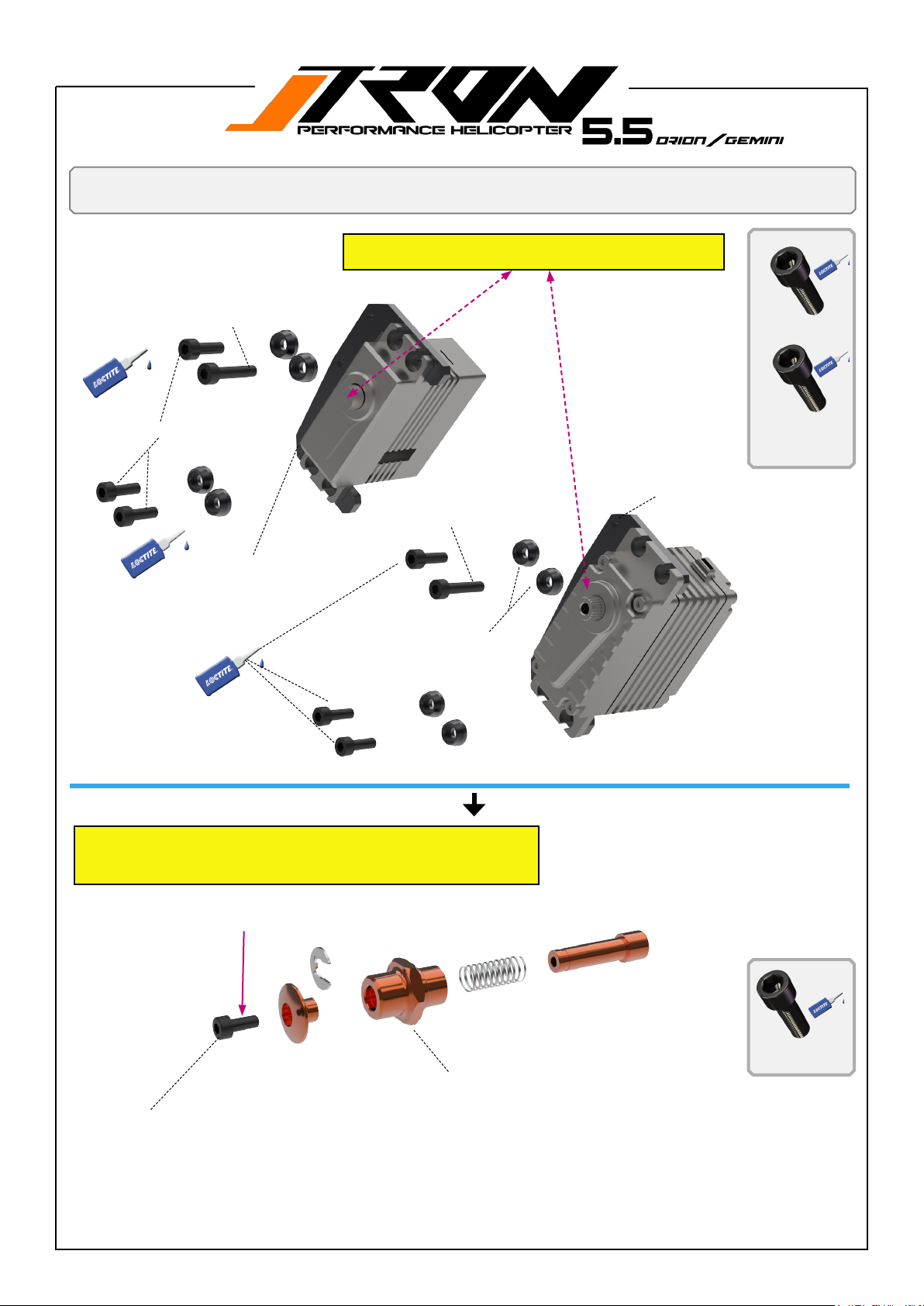
You will need:
Loctite 243 = blue
Tail servo mount / battery release knop
Pay attention to the orientation of the servo horn arm and
the position of the spline when assembling to the frame!
1*M2.5x12mm Hex-Socket-screw
A
B
3*M3x8mm Hex-Socket-screw
A
A
Tail mini size Servo Mount
TR501-127
M3x8mm Hex-Socket-screw
Midi size tail servo.
1*M3x12mm Hex-Socket-screw
A
TR501-102 Black anodized
washers / 2.5mm x 8
A
A
A
3*M2.5x8mm Hex-So-
cket-screw
!
Tail Full size Servo Mount
TR501-128
B
B
1*M2.5x12mm Hex-So-
cket-screw
Supersonic batterie release knob is pre assembled at the factory.
Disassembling is not required.
Only remove M 2.5*8 screw, add loctite 243 and screw it back.
Add loctite 243 to the M2.5*8mm screw!
A
!
TR550-420 Release knop for battery tray
M2.5x8mm Hex-Socket-screw
(pre assembled by factory)
Full size tail servo.
A
M2.5x8mm Hex-Socket-
screw
Page 34
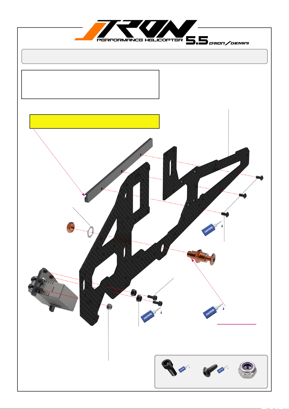
You will need:
Loctite 243 = blue
1. Assemble battery rail guide to the upper main frame. Pay attention to the correct way the guide is mounted!
2. Assemble battery release knob assembly to the main frame.
3. Assemble tail servo frame ( full size or mini ) with the tail servo
assembled to the upper right main frame.
Note the orientation of the rail, which is facing towards the inside and the guide rail is facing up.
Upper right frame assembly Orion /Gemini
!
TR505-201 Upper right main frame.
B
Steel spring shim
2*M2.5x6mm Hex-So-
cket-screw
A
A
TR501-102 Black anodized washers / 2.5mm x 8
B
3*M2.5x6mm Hex
panhead screw
!
Apply loctite !
B
1* Lock nut M2.5mm
A
4*M2.5x6mm Hex-So-
cket-screw
B
3*M3x6mm Hex pan-
head screw
C
1* Lock nut M2.5mm
Page 35
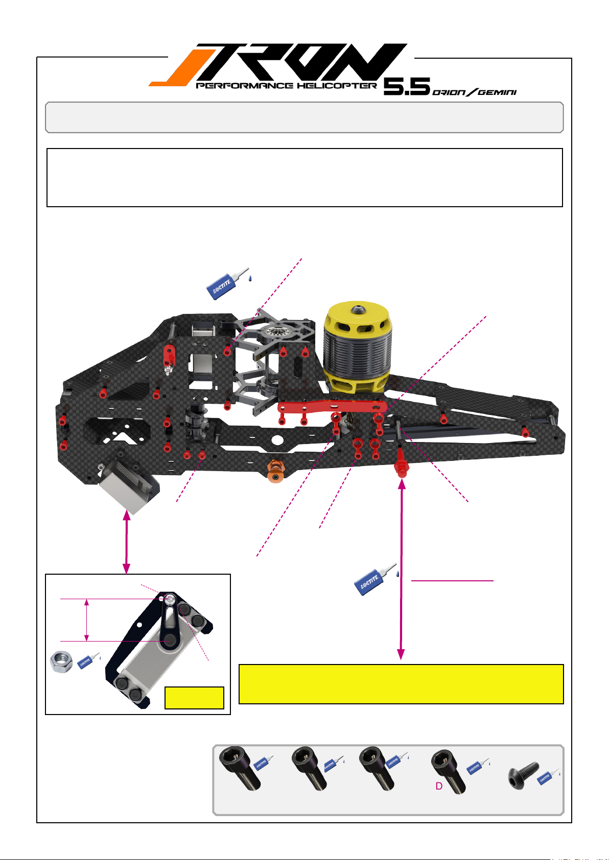
You will need:
Loctite 243 = blue
1. Assemble motor support stienrer to the uppar right mainmain frame. Do not tighten and loctite screws A and B yet.
2. Push motor mounts support towards the rightside and slightly secure the motormount. This will be benetial for
convinient main gear assembling later on.
3. Assemble canopy stands-o for back and front (supersonic mounts backside)
4. Assemble tail servo horn accordingly gure 1.
Upper right frame assembly Orion/Gemini
12*A =M3x6mm Hex-Socket-screw
TR501-102 Black anodized washers 2*
D
A
A
A
A
A
A
E
2*E=M3x6mm Hex panhead screw
TR550-112 Pivot steel ball set for servo horns
15mm
A
A
A
B B
A
E
2*D =M3x8mm Hex-Socket-
2*C=M3x12mm Hex-Socket-screw
screw
A
A
B
B
TR501-219 Frame spacers
Apply loctite !
1* Nut M2 for secure
pivot steel bal
1* Nut M2
Figure 1
ORIONstylefrontcanopystandomounting
position
A
12*M3x6mm Hex-Socket-screw
B
2*M3x10mm Hex-Socket-screw
C
4*M3x12mm Hex-Socket-screw
D
2*M3x8mm Hex pan-
head screw
E
5*M3x6mm Hex pan-
head screw
Page 36
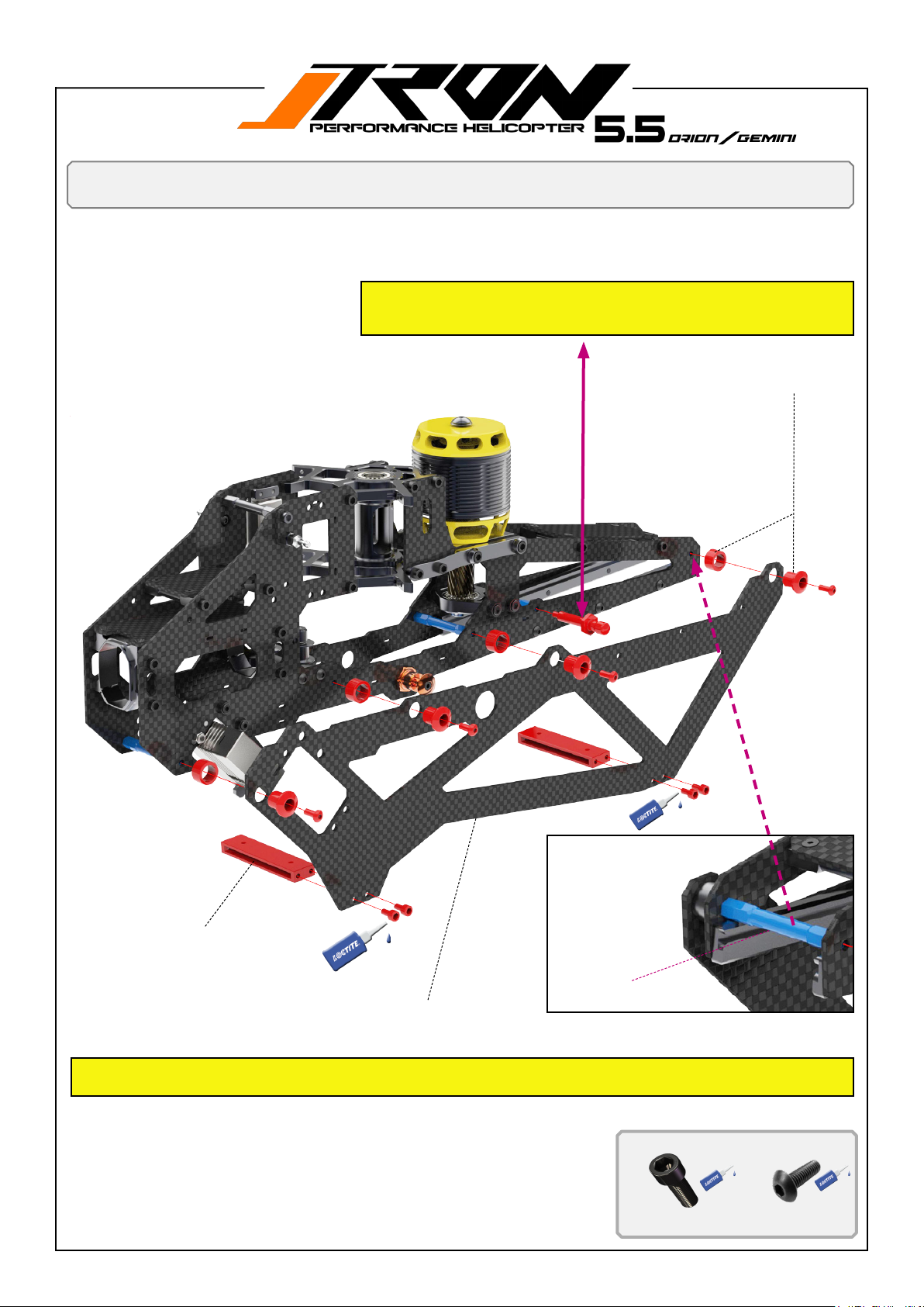
You will need:
Loctite 243 = blue
Lower Orion frame assembly
ORIONstylefrontcanopystandomounting
position. Already assembled on page 35!
Lower ORION frames.
Left and right side are identical.
B
4*break way part TR503-968
B
B
B
A
A
A
TR550-207 Landing gear support
TR505-203 lower frame Orion
Pay attention to the 4 blue color frame spacers =TR501-219 which need to be added in this step to support the lower 2
side frames. Apply to Orion and Gemini.
A
TR501-219
A
4*M3x6mm Hex-Socket-
screw
B
4*M3x8mm Hex pan-
head screw
Page 37
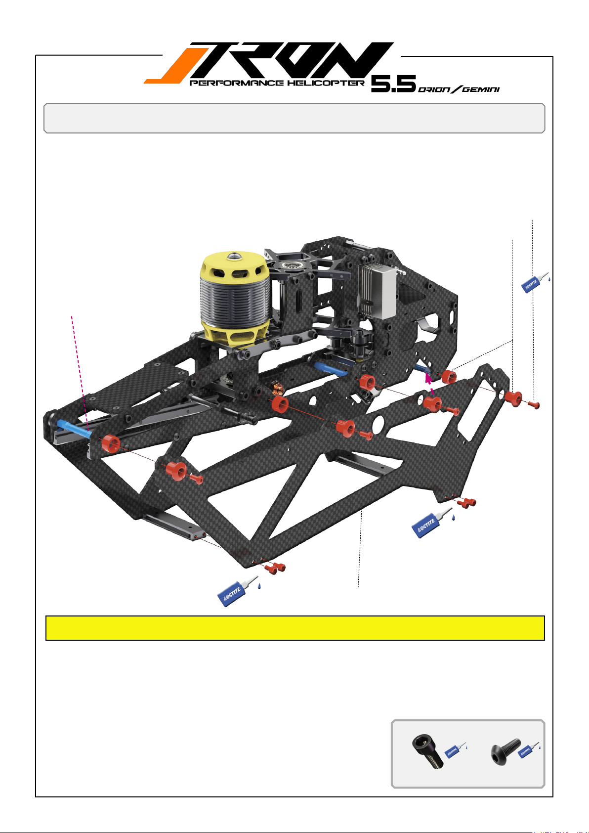
You will need:
Loctite 243 = blue
Lower Orion frame assembly
4*M3x8mm Hex-Socket-screw for left side and right side lower Orion frame
TR501-219 Frame spacer
4*breack way TR503-968 on left and right
side lower Orion frame
B
B
B
B
A
A
A
A
TR505-203 lower frame Orion
Pay attention to the 4 blue color frame spacers =TR501-219 which need to be added in this step to support the lower 2
side frames. Apply to Orion and Gemini.
A
4*M3x6mm Hex-Socket-
screw
B
5*M3x8mm Hex pan-
head screw
Page 38
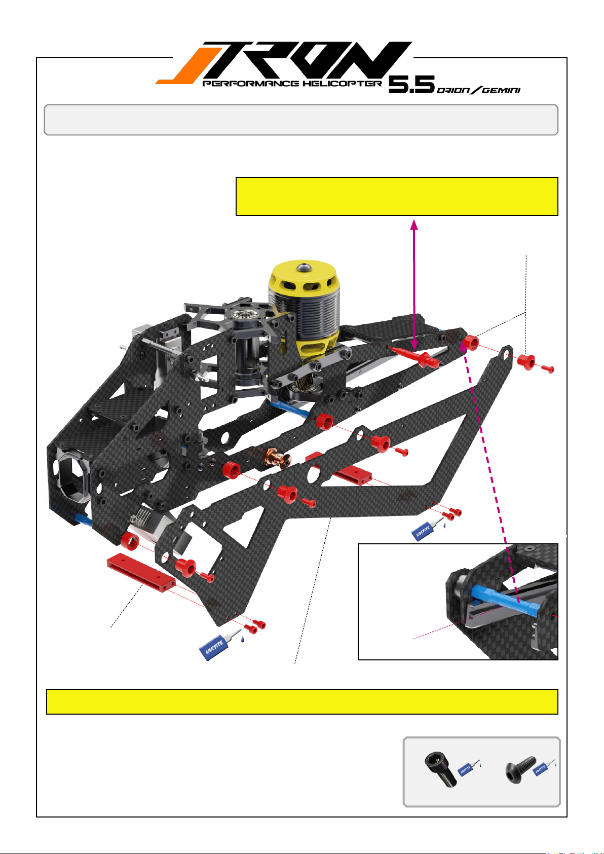
You will need:
Loctite 243 = blue
Lower Gemini frame assembly
GEMINIstylefrontcanopystandomounting
position.
Lower GEMINI frames.
Left and right side are identical
4*break way part TR503-968
B
B
B
A
A
B
TR501-219 Landing gear support
TR505-204 lower frame Gemini
Pay attention to the 4 blue color frame spacers =TR501-219 which need to be added in this step to support the lower 2
side frames. Apply to Orion and Gemini.
A
A
TR501-219
A
4*M3x6mm Hex-Socket-
screw
B
4*M3x8mm Hex pan-
head screw
Page 39
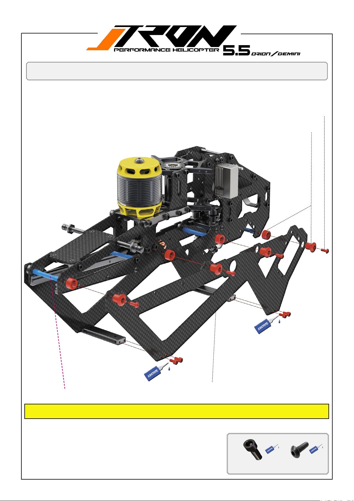
You will need:
Loctite 243 = blue
Assembling lower GEMINI frames.
Left and right side are identical.
Lower Gemini frame assembly
4*M3x8mm Hex-panhead-screw for left side and right side lower Orion frame
4*breack way TR503-968 on left and right side lower Orion frame
B
B
B
A
A
A
A
TR501-219 Frame spacers
Pay attention to the 4 blue color frame spacers =TR501-219 which need to be added in this step to support the lower 2
side frames. Apply to Orion and Gemini.
TR505-204 lower frame Gemini
B
A
4*M3x6mm Hex-Socket-
screw
B
5*M3x8mm Hex pan-
head screw
Page 40
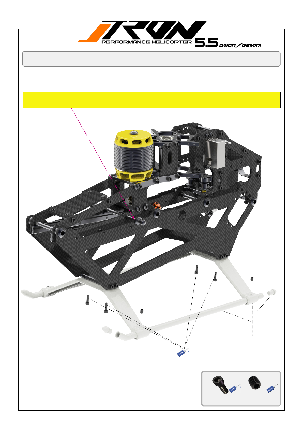
You will need:
Loctite 243 = blue
Landing gear assembly
Render do show ORION style front canopy mounting stands o position and ORION frame
style. Landing gear assembly is identical for Orion and Gemini.
A
B
A
A
B
A
Landing gear set TR550-133 or
Landing Gear 1 Pair TR504-123
A
4*M3x10mm Hex-So-
cket-screw
B
B
4*M4x4mm set screw
Page 41
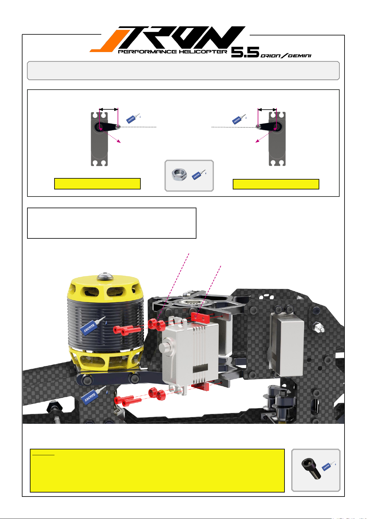
You will need:
Loctite 243 = blue
Cyclic servo assembling
( 15-16mm)
TR550-112 Pivot steel ball set for
servo horns.
Pay attention on the orientation of the servo horn arm and
Right cyclic servo ( Nr.3 / v-bar)
We added 2mm CF servo shims to the kit. For servos of certain brands
with larger dimensions. This allows more clearance from the wires versus
the main frame while mounting them to the servo frames. (CF plates can
be found in the spare parts bag inside the kit)
the position of the spline.
2*M2* nut
4* TR501-102 Black anodized washers
( 15-16mm)
Left cyclic servo ( Nr.2 / v-bar)
2* TR505-216
A
A
A
A
Tech tip!
Use 2* M2.5*6mm screws crosswise for easy centering by the screw head when align servo position. Assemble the M2.5 scew until the head enters the recess of the servo mounting holes. Then
use the other 2 crossbars to x the servo. Remove the temporary center screws and mount the
remaining M2.5x10mm with the washer.
A
4*M2.5x10mm Hex-So-
cket-screw
Page 42
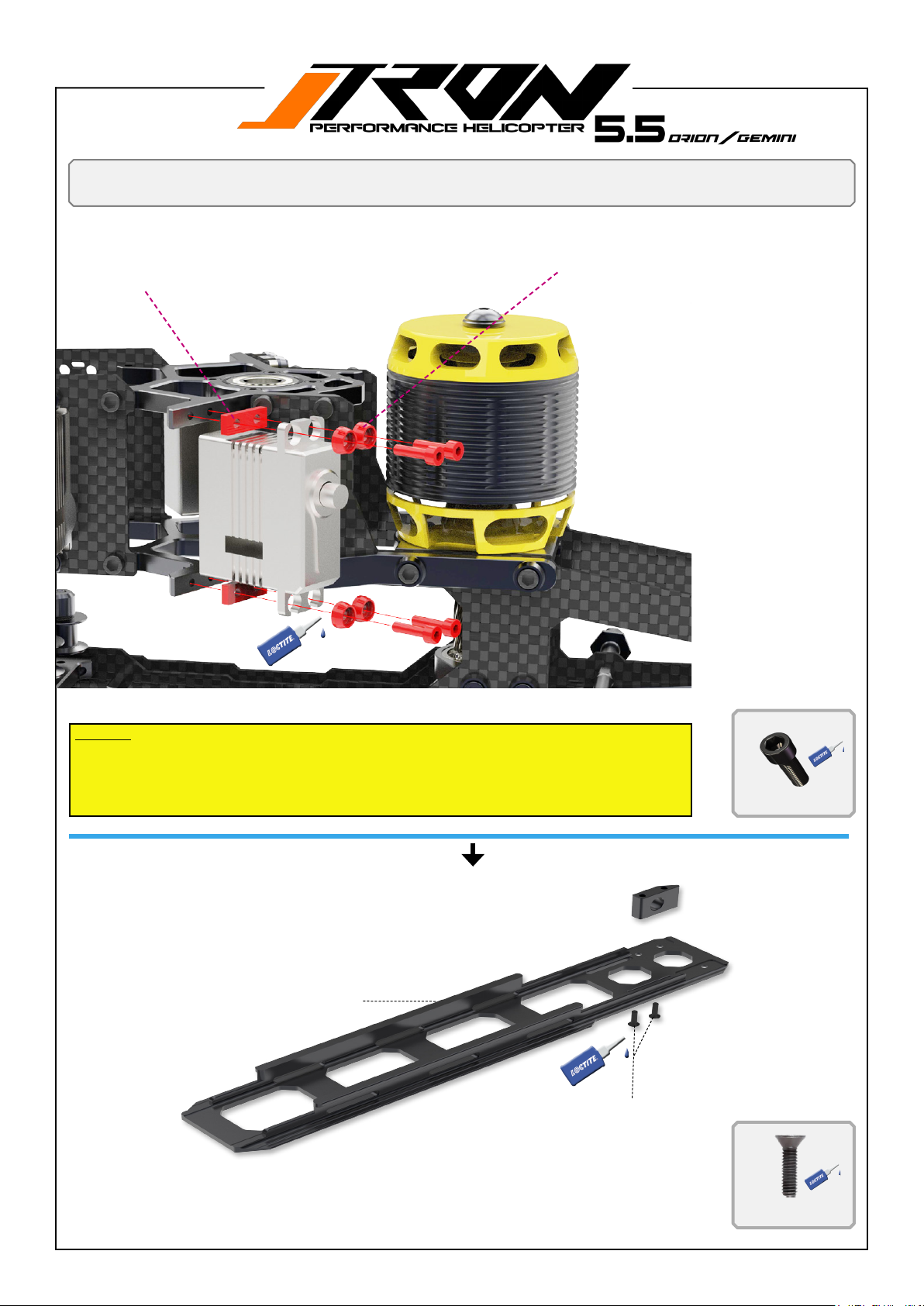
You will need:
Locktite 243 = blue
2* TR505-216
Pitch servo assembling and battery tray
4* TR501-102 Black anodized washers
A
A
A
A
Tech tip!
Use 2* M2.5*6mm screws crosswise for easy centering by the screw head when align servo
position. Assemble the M2.5 scew until the head enters the recess of the servo mounting holes.
Then use the other 2 crossbars to x the servo. Remove the temporary center screws and
mount the remaining M2.5x10mm with the washer.
TR550-712 Battery tray assembly
A
4*M2.5x10mm Hex-So-
cket-screw
2*M2.5*8mm countersunk hex screw
A
2*M2.5x8mm counter-
sunk hex screw
Page 43
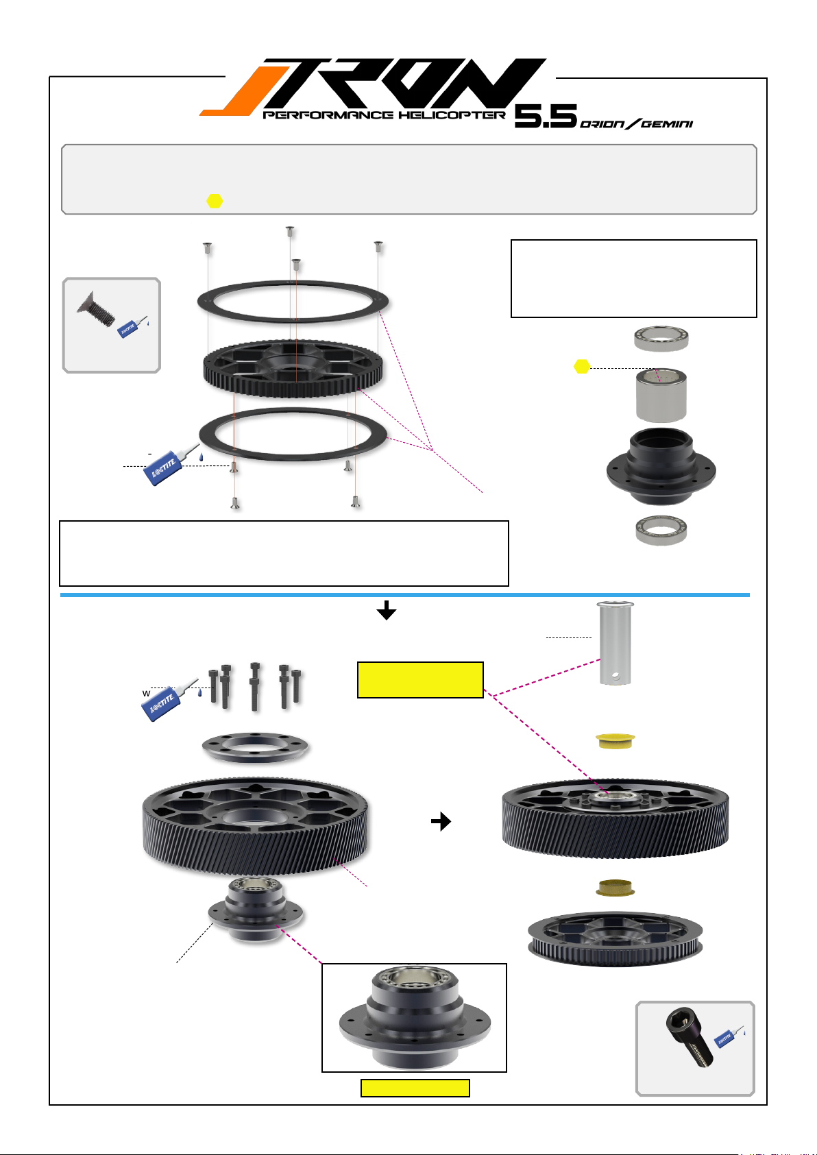
You will need:
Loctite 243 = blue
Grease or oil
B
B
8*M2.5x4mm Hex-Socket-screw
Main drive preparation
B
B
B
One way drive assembly is preassembled
at the factory.
Disassembling is not required.
Only add a few drops of oil to the one way
bearing if you like.
M2x4mm Hex-So-
cket-screw
B
B
Main drive assembly is preassembled at the factory.
Disassembling is not required.
Just remove 8*A=M2.5x12mm screw and 8*B=M2x4mm add loctite 243 and
screw back.
8* A
8*M2.5x12mm
Hex-Socket-screw
B
B
TR501-304 One way bearing sleeve
including 2 bushings
Add a few drops of
oil or grease.
TR550-580 Tail belt front pulley.
HD oneway drive inclusive
OWB TR550-524
TR503-136 Machined delrin
main gear 136T
Note orientation!
A
8*M2.5x12mm Hex-Socket-screw
Page 44
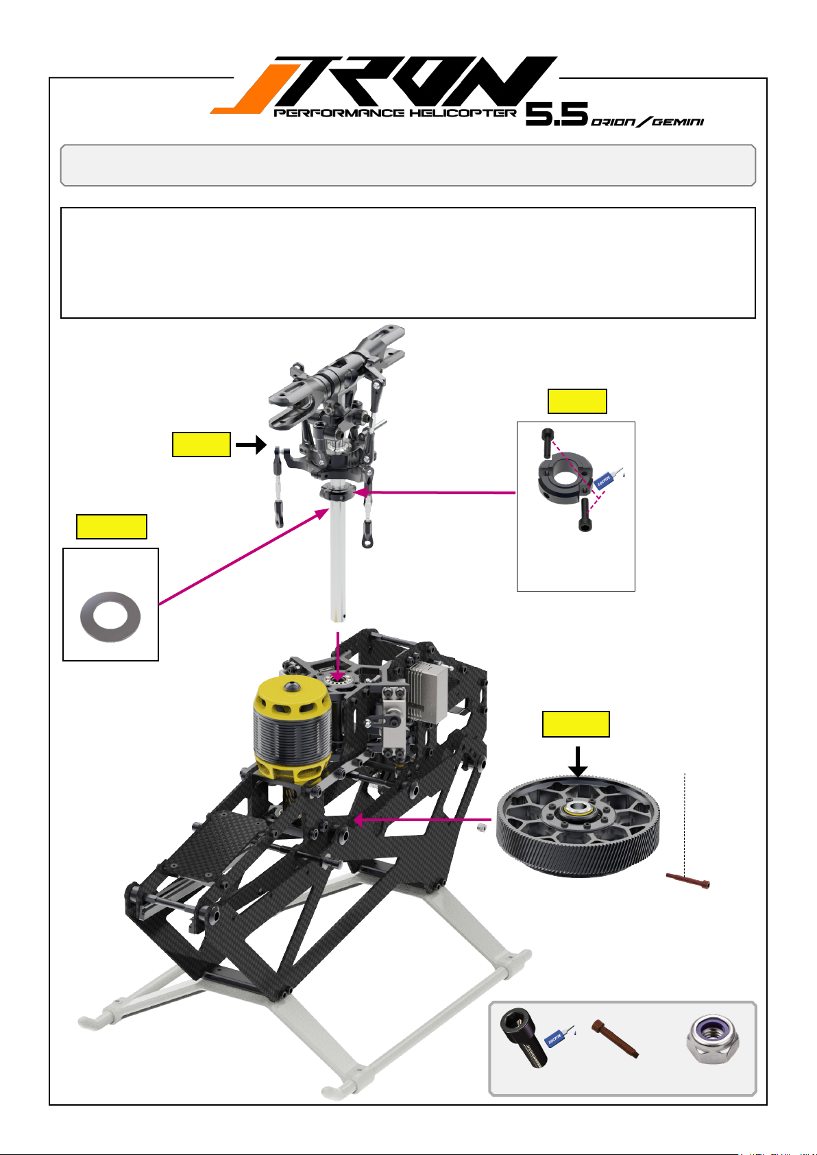
You will need:
Loctite 243 = blue
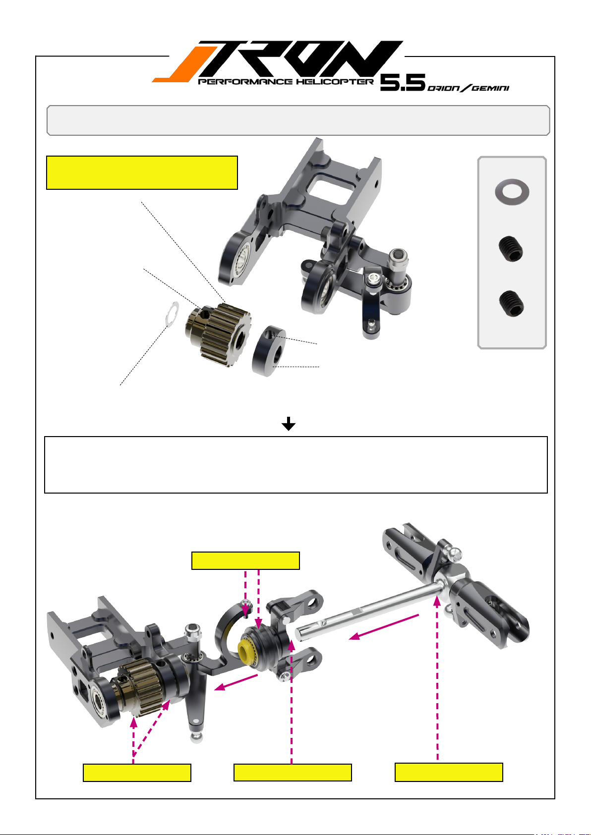
1. Insert main gear assembly into frame = step 1
2. Insert rotor head assembly through bearing support tube, dont forget to add shim E = step 2 and 3.
3. Make sure your main shaft glide true the one way bearing sleeve and line up with the jesus bolt screw holes.
4. Insert jesus bolt screw, B and secure it with the M3 nut lock, C
5. Move down the main shaft collar to have zero up and down play on the rotor head assembly, then tighten screw A
step by step = step 4.
6. Make sure to have an equal gap on the collar to achieve best holding results for the main shaft= step 3
Assembling head and maingear to frame
step 4
step 2
Add shim now.
(page 15)
E
1* Shim 1x10x0.3mm
step 3
A
A
Tighten screws now.
2*M3x12mm HexSocket-screw
step 1
1* jesus bolt spez scew. TR587-326
C
A
2*M3x12mm Hex-Socket-screw
B
1* jesus bolt spez scew:
TTR587-326
B
C
1* Lock nut M3
Page 45
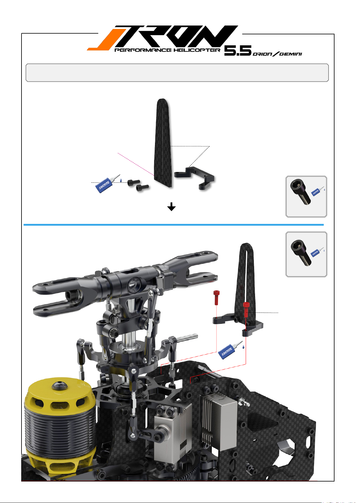
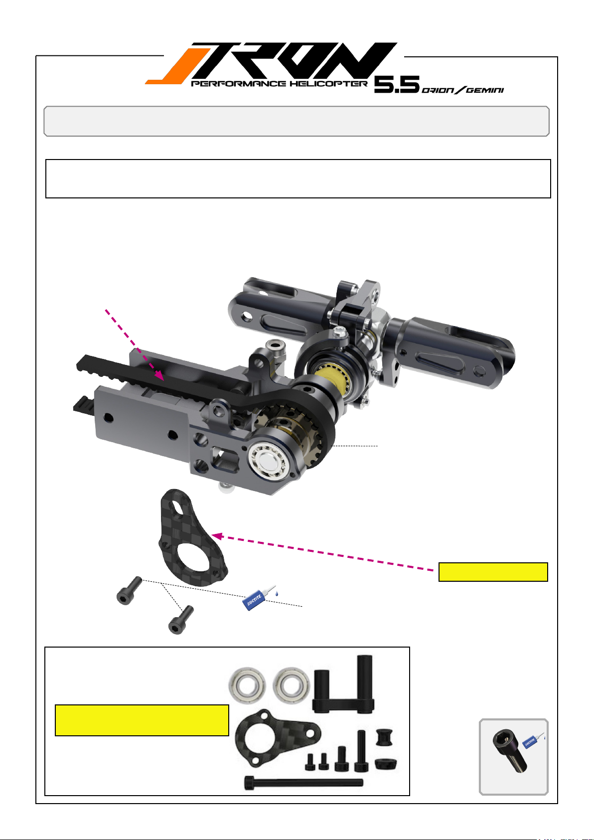
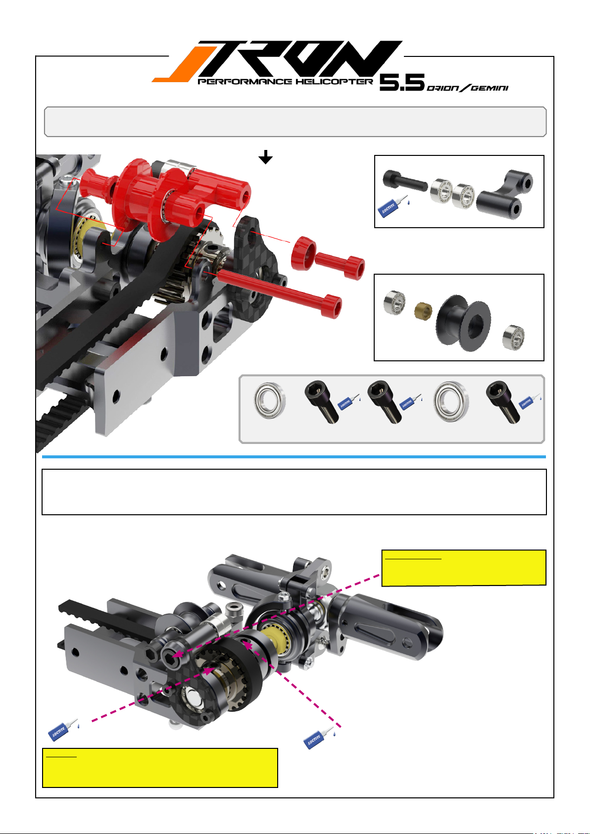
You will need:
Loctite 243 = blue
Anti rotation guide
Sanding the edges on the guide
makes assembly easier.
M2.5x6mm Hex-Socketscrew
TR550-202 Anti rotation guide.
A
A
A
2*M2.5x6mm Hex-Socket-screw
B
2*M2.5x8mm Hex-So-
cket-screw
B
B
M2.5x8mm Hex-Socket-
screw
Page 46
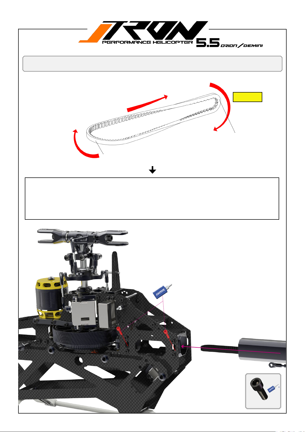
You will need:
Loctite 243 = blue
Ensure to have your tail belt oriented as shown in the illustration
Tail boom to main frame assembly
Figure 1
Back (tail rotor side)
Front (main frame side)
1. Insert boom as shown into the tail boom clamps, pay attention to the corect orientation of the tail belt.
2. Slide the belt through the idler pulleys from the belt tensioner, use a cable tie for help.
3. Pull the tail belt over the front belt drive pulley.
4. Pull the boom backwards and apply tension to the belt.
5. Tighten the boom clamp screws with screw A. Add loctite 243 / blue!
6. Ensure the tail is rotation in the corect direction when turning the main rotor head clockwise. ( Figure1 )
7. Apply ( 3 ) turns on the belt tensioner set screw. See also page 51.
2*M3x12mm Hex-Socket-screw
A
A
A
2*M3x12mm Hex-Socket-screw
Page 47
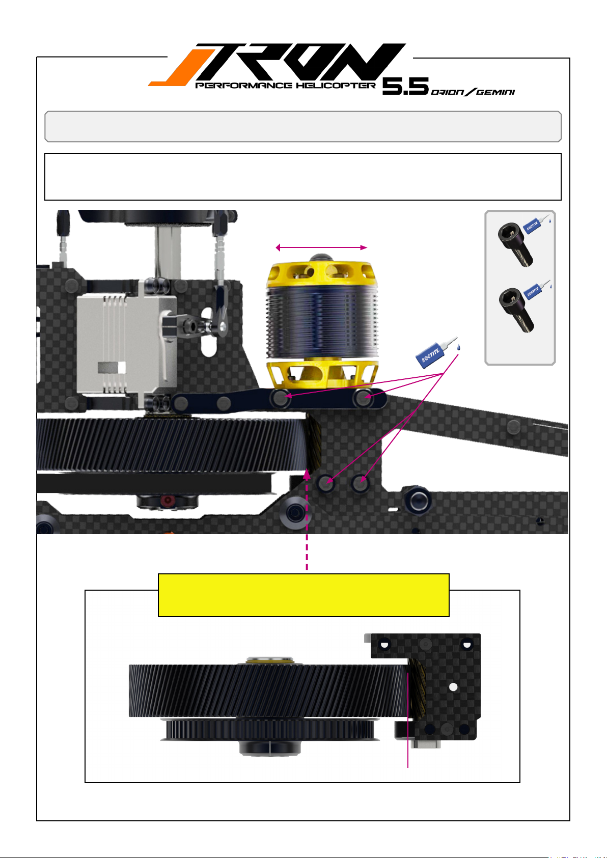
You will need:
Loctite 243 = blue
1. Set gear mesh as shown beow in the illustration ( 0,1mm gap )
2. Carefully thighten screws A crosswise left and right while you slightly pressing down the motor mount to have it 90
degree to the main gear. Use loctite 243 = blue on all A and B type screws!
3. Make sure after all A screws are thight the main gear turn free with a minimal gear play.
Adjusting motor pinion verus main gear
Decrease mesh Increase mesh
B
2*M3x8mm Hex-Socket-
screw
A
2*M3x12mm Hex-So-
cket-screw
A
Tech tip!
Ensure proper gear mesh by adjusting the gears until they engage smoothly
without excessive play or tightness. Proper gear mesh is critical for optimal
performance and longevity of the components.
A
B
B
(0.1mm) gear mesh
Page 48
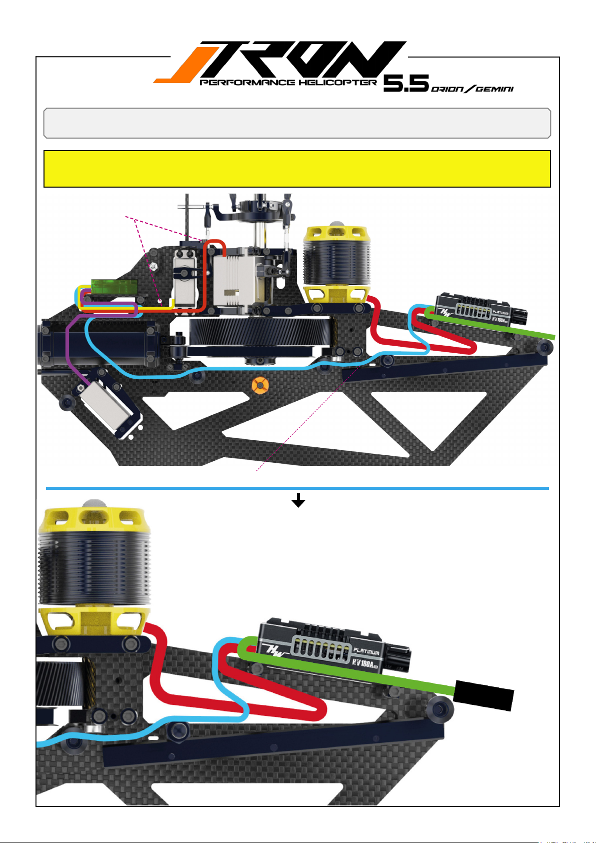
Tipps!
Tech tip!
You may want to use servo wire protection shrink tube to avoid cung or cutting on servo wires. Please make sure all
edges on the frames which are in contact with wires are eased with sandpaper.
Servo to FBL cables routing
Wiring electronics
ESC to FBL cables routing ( routing can be done inside the frames)
Page 49
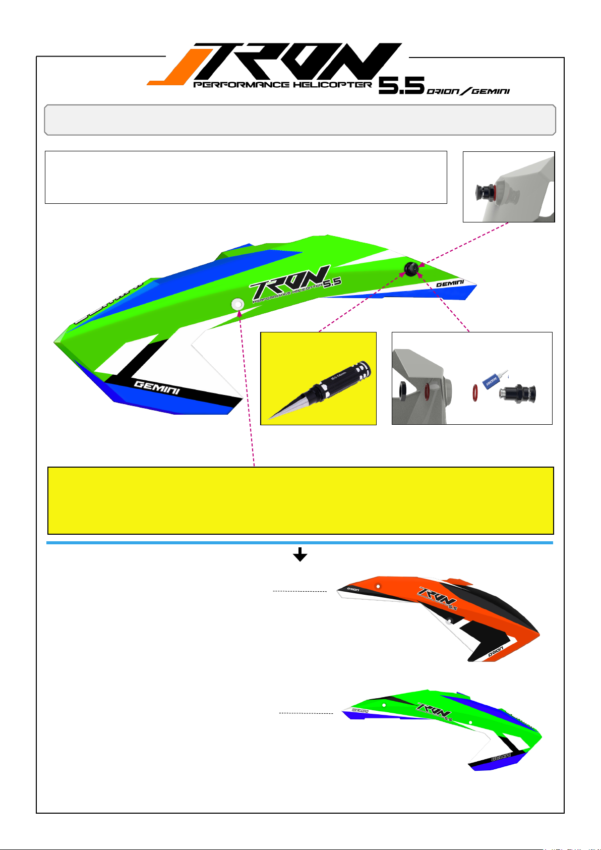
You will need:
Loctite 243 = blue
1. Enlarge the real canopy holes to (9mm) use a propper canopy reamer!
2. Assemble the supersonic mounts as shown in the illustration ( use loctite to secure the
nuts )
3. Use the rubber grommets for the front holes.
Canopy
Use a canopy reamer to enlarge the holes to t the supersonic canopy mounts.
Tech tip!
You may need to slightly enlarge the canopy mounting holes to perfectly t the supersonic canopy mounts. Please use
a proper canopy reamer and NOT an ordinary drill!
Use CA glue for the two front canopy grommets. Slightly chamfer the front holes on the canopy for the grommets to
extend their lifespan.
Orion Canopy orange black TR502-154
TR505-245 Supersonic
rear canopy mounts
Gemini Canopy neongreen shockblue
TR502-163
Page 50
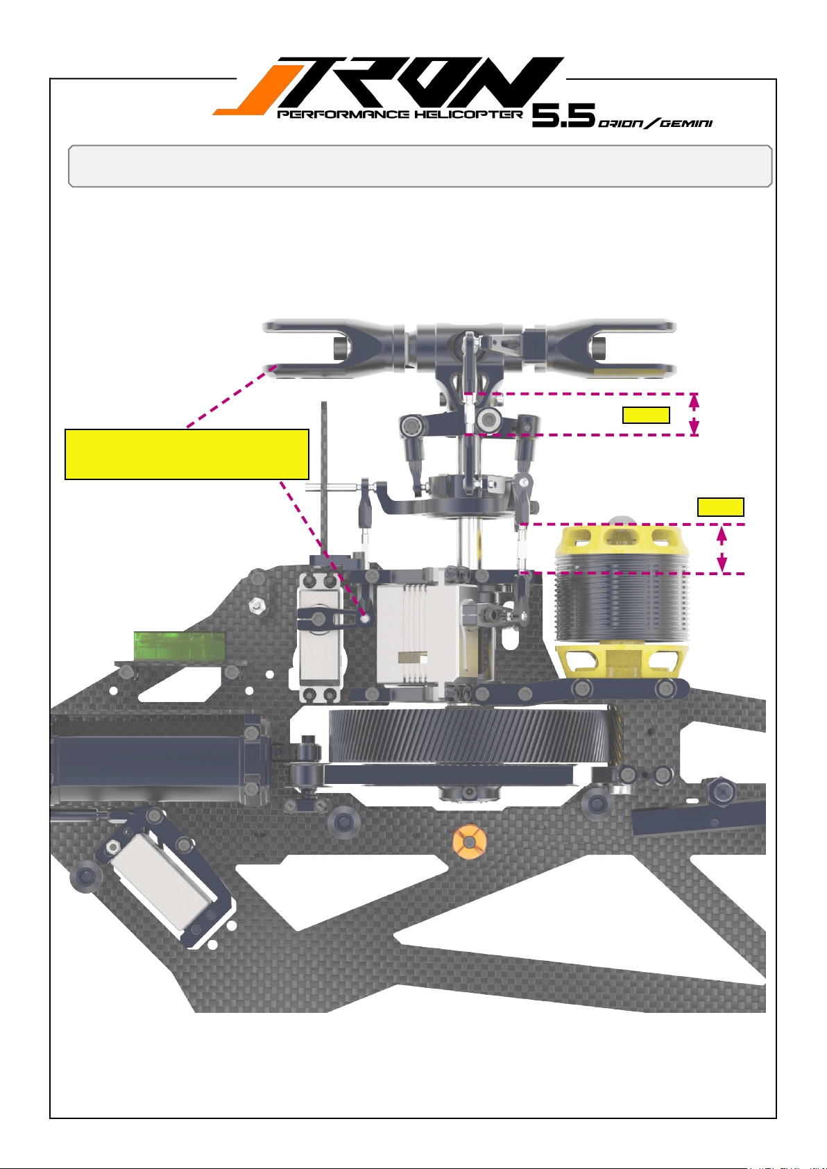
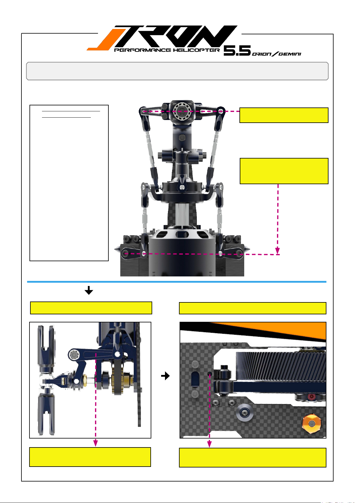
• Zero degree pitch at center stickposition
• Cyclic servos at 90 degrees position
Final setup and pre-ight check
15mm
(19mm)
Page 51
Final setup and pre-ight check
1. Disconnect your Motor
wires from the ESC!
2. FBL controller should be
set to the mode where
you can level your servo
center position and, or
swashplate level mode.
3. Fine tune your servo
center position as precise
as you can by the position
of the servo horns. For
netuning use Sub trims in
the FBL software.
4. Adjust your linkage from
the servos to the swashplate as shown in the
illustration. (90 degree)
5. Adjust your swashplate
to Blade grip linkage to
achieve 0 pitch at center
stick position.
6. Continue setup as required in your FBL controller
software.
• Zero degree pitch at center
position.
• Zero degree pitch at center
stick position
• Cyclic servos at 90 degrees
position
Tail rotor linkage setup.
For best tail authority performance adjust center position of your tail pushrod linkage ( tail servo) same as
shown in the illustration ( 90°) degree.
Belt tensioner setup.
A
After tightening the tail belt by pulling the tail boom backwards,
pre-load the set screw A on the belt tensioner with three full
turns. No further adjustments are required after this step.
Page 52
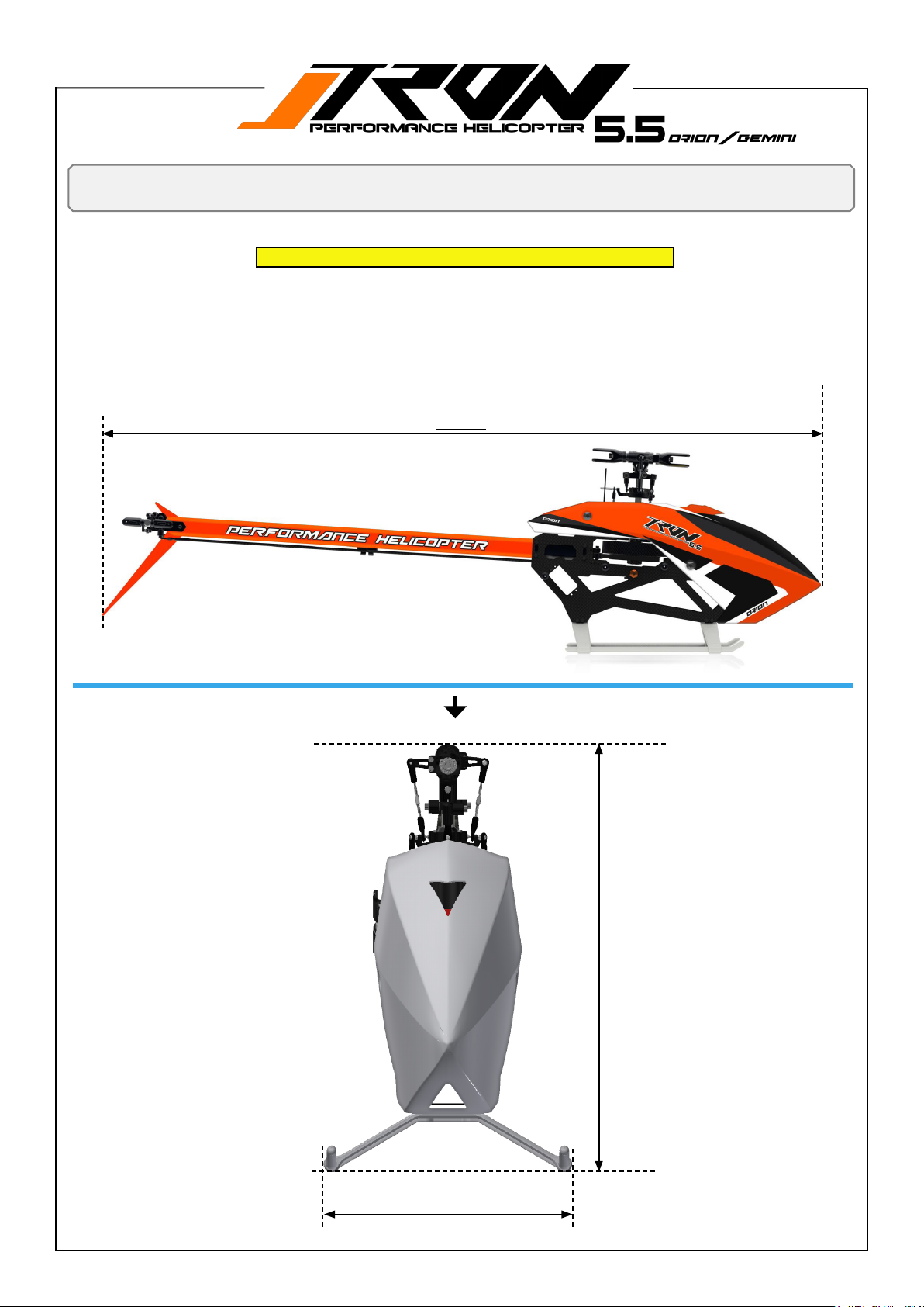
Dimensions and wheight
Tron 5.5 ORION and GEMINI have identical dimensions
1. Dry weight = 1630 gram without blades and electronics
2. With = 194mm
3. Heigth = 318mm
4. Length = 1135mm
5. Max main blade size = 560mm
6. Max tail blade size = 98mm
1135mm
194mm
318mm
Page 53
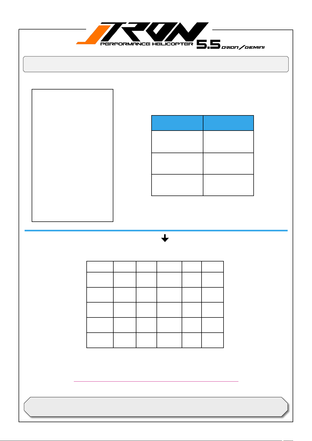
1. Make sure your battery tray is
securely locked. Use 2 -3 battery straps.
2. Inspect your blades for possible
damage and if they are slightly
tighten.
3. Inspect your linkages if they are
all in place and not have been
popped o turing transport of
your model.
4. Conrm that the FBL unit is
correctly initialized.
5. Make sure your canopy is secured safely.
6. If you are a beginner, always
seek advice by a experienced
pilot, especially for your rst
ight.
7. Do regular maintanance and
inspect Ball links for wear and
also Tail belt, main gear and bearings. Make sure your srcews
remain save and tight.
Preight check and gear ratios
Recommended head speed.
Flying styles Head speed
Beginner and sport
ying.
Advanced sport, 3D
ying.
Hardcore3Dying.
1800-2400rpm.
2400-2600rpm.
2600-2800rpm.
Main and tail rotor gear ratios.
Main gear Pinion Ratio Tail drive Tail Ratio
136
136
136
INCLUDED IN KIT
136
136
Make sure to check your model on a regular basis, do a preight check every time you plan to y
Max. head speed for main rotor head must not exceed 3000 RPM!
For sales: [email protected] / for support: [email protected]
13T /6mm
14T /6mm
15T/6mm
16T/6mm
17T/6mm
10.46 80T 18T 4.44
9.71 80T 19T 4.21
9.06 80T 20T 4.00
8.50
8.00
your model.
Contact:
tronhelicopters.com
INCLUDED IN KIT
 Loading...