

Page 1
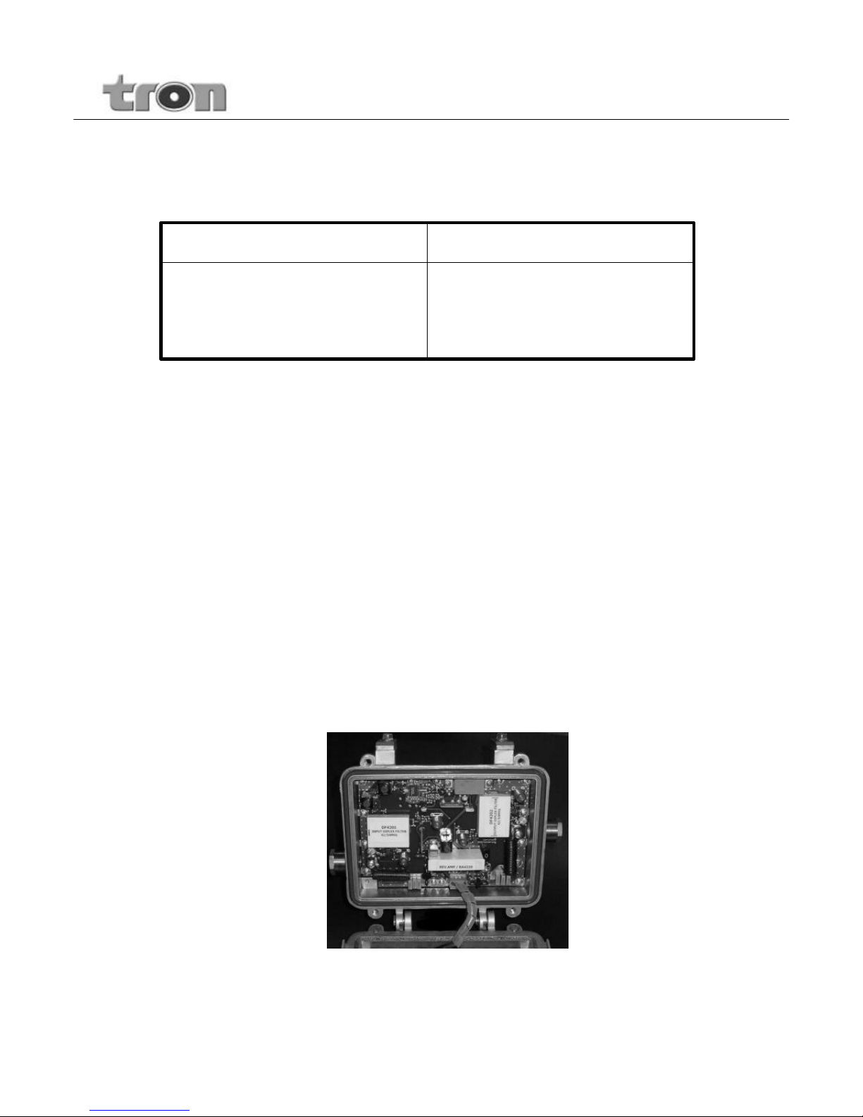
TLE 35128R Two Way 870MHz CATV
Distribution Amplifiers
5-30 / 47-870 MHz
5-42 / 54-870 MHz
5-65 / 85-870 MHz
TLE35128
Bandwidths Model
TLE35128 series CATV Distribution Amplifiers are broadband outdoor, with GaAsHybrid / Power Doubler technology designed for the cable powered (35-90VAC)
distribution systems where a high quality low noise figure ampl ifier is necessary
to amplify the signals in both the forward and return paths.
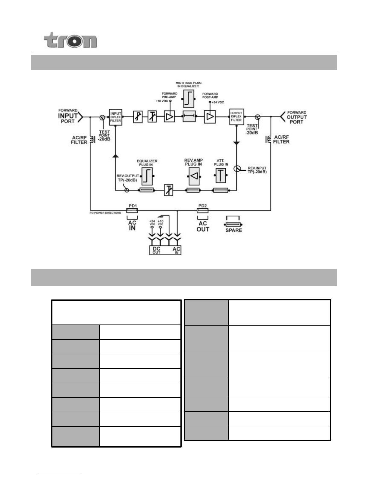
These are all designed with flat operational gain of 35 dB in the forward bandwidth
and 20 dB in the reverse bandwidth with a plug-in module. They have an input
variable equalizer and plug-in interstage equalization feature in the forward
bandwidth, a post stage plug-in equalization feature in the reverse bandwidth.
Forward bandwidth features 20 dB variable gain control at the in put stage.
Reverse bandwidth features a fixed value attenuator pad at the input stage and a
20dB variable gain control attenuator at the output stage.
These amplifiers are remote powered, 35-90VAC over coaxial network .
User Manual
TLE35128 _usermanualV3_Sept 06
Page 2
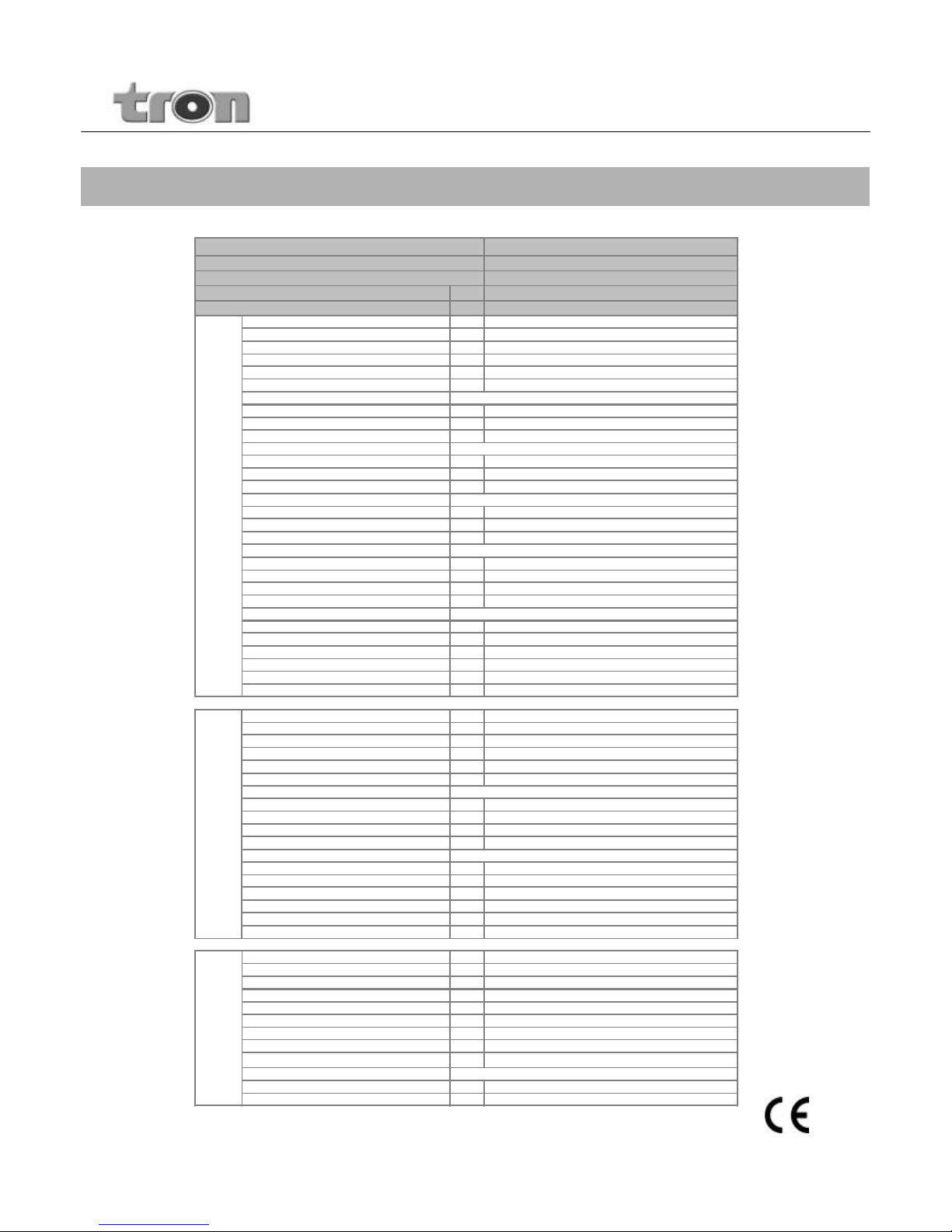
Technical Specifications
Specifications are subject to change without notice
Typical, for T=20degC, Zin=Zout=75ohms
User Manual – TLE35128
MHz
MHz
Gain dB
Gain Response Flatness dB
Gain Control dB
Cable Slope Control dB
Interstage Equalizer Control dB
RF Test Points dB
Distortions, EN50083-3
CTB dBc
CSO dBc
XMOD dBc
Distortions, EN50083-3
CTB dBc
CSO dBc
XMOD dBc
Distortions, 79 Channels
CTB dBc
CSO dBc
XMOD dBc
Distortions, 79 Channels
CTB dBc
CSO dBc
XMOD dBc
Noise Figure dB
Group Delay (with 42/54 Diplex Filters)
48.25 - 52.83 MHz nSec.
55.25 - 58.83 MHz nSec.
61.25 - 64.83 MHz nSec.
Other nSec.
85-86 MHz nSec.
Return Loss (Input & Output) dB
TLE35128
Technology GaAs - Hybrid Power Doubler
Model
Remote 30-90VAC, cascadable
Bandwidth-Forward (Plug-in Diplex Filters) 47-862 / 54-862 / 85-862
Powering
Bandwidth-Reverse 5-30 / 5-42 / 5-65
F
o
r
w
a
r
d
P
a
t
h
35
+/- 0.75
0..-20 , continious , input
0..-20 , continious, input
Plug-in / 0, 2, 4, 6, 10, 12, 14, 20
-20dB, input & output
Cenelec 42 Ch. -60dBc, Flat output
112
115
108
Cenelec 42 Ch. -60dBc, 10dB interstage slope
114
117
110
-16
47dBmV Flat Output
10dB Interstage Slope (54-862MHz), ref 47dBmV
-72
-68
-61
-78
-74
-65
6
max. 30
max. 30
max. 15
max. 4
max. 10
Gain dB
Gain Response Flatness
Gain Control - Input dB
Gain Control - Output dB
Cable Slope Control - Output dB
RF Test Point dB
Distortion 4 Channel
CTB dBc
CSO dBc
XMOD dBc
Return Loss (Input & Output) dBuV
Group Delay (with 42/54 Diplex Filters)
5-6 MHz nSec.
13-14 MHz nSec.
29-30 MHz nSec.
41-42 MHz nSec.
64-65 MHz nSec.
Noise Figure dB
AC Input VAC
Power Consumption W
Hum Modulation dB
Surge Withstand
Port Current A
AC Power Direction
RFI Isolation (5-1000MHz) dB
Temperature degC
Water Immersion
Dimensions mm
Weight kgs
R
e
v
e
r
s
e
20dB
+/- 0.50
max. 20
max. 30
40dBmV flat output
-61
-86
Fixed Value Plug-in / 0, 2, 4, 6
0..-20 , continious
Fixed Value Plug-in / 0, 2, 4, 6, 8, 10
7
max. 20
G
e
n
e
r
a
l
Input and Output Ports
over coaxial network, 30-90VAC
14.5W(with reverse amplifier module- 1.3W)
15psi for 10 seconds @ 20degC
<-100
-100 @ 10A
@all ports , IEEE C62.41 Cat B3 (6kV,3kA)
IN, OUR or THRU
-40 to +55
190*170*75
1.6
max. 50
max. 4
-78
-16
-20dB, output
Standard 5/8''-24UNEF stainless steel bushing
Typ=10 , Max=15
Page 3
Forward Equalizer Module,
XX : ( Value in dB) : 2-4-6-10-12-14-20dB
(0dB factory pre-installed)
9PEQ2-862/xx
Output Diplex Filter Module,
for 42/54MHz version
DF4202
Input Diplex Filter Module,
for 30/47MHz version
DF3001
Output Diplex Filter Module,
for 30/47MHz version
DF3002
Note:
All products are factory installed with 1 set of Diplex Filters, 0dB
Attenuator Pad and 0dB Equalizer Modules on the Reverse and
Forward Paths.
Input Diplex Filter Module,
for 65/85MHz version
DF6501
Definition
Ordering Code for
Accessories
Input Diplex Filter Module,
for 42/54MHz version
DF4201
Output Diplex Filter Module,
for 65/85MHz version
DF6502
Reverse Amplifier Module
for 65/85MHz version
RA6520
Reverse Amplifier Module
for 42/54MHz version
RA4220
Reverse Equalizer Module for
65/85MHz version
XX: (Value in dB) : 2-4-6-8-10 dB
(0dB factory pre-installed)
REQ-65/xx
Reverse Equalizer Module for
42/54MHz version
XX: (Value in dB) : 2-4-6-8-10 dB
(0dB factory pre-installed)
REQ-42/xx
Reverse Equalizer Module for
30/47MHz version
XX: (Value in dB) : 2-4-6-8-10 dB
(0dB factory pre-installed)
REQ-30/xx
Reverse Fixed Attenuator Pad
XX: (Value in dB) : 2-4-6-8-10-12dB
(0dB factory pre-installed)
RFA/xx
Reverse Amplifier Module
for 30/47MHz version
RA3020
Ordering Information
Block Diagram TLE35128
User Manual – TLE35128
Page 4
CAUTION
The exclamation point within an
equilateral triangle is intended to alert
you to the presence of important
operating and maintenance (servicing)
instructions in the literature
accompanying the product.
The Lightning flash with arrowhead symbol within
an equilateral triangle is intended to alert you to
the presence of uninsulated " dangerous voltage "
within the products supplementary external power
supply enclosure that may be of sufficient
magnitude to constitute a risk of electrical shock to
persons.
Risk of Electric Shock
Do not Open Power
Supply section
WARNING : AC POWER IS PRESENT AT CONNECTOR TERMINALS
REMEMBER TO REPLACE COVER AFTER ADJUSTING. COVER MUST BE IN PLA CE FOR CE, SAFETY AND
PROTECTION
NO SERVICEABLE PARTS INSIDE. REFER SERVICING TO QUALIFIED SERVICE PERSONNEL .
Safety
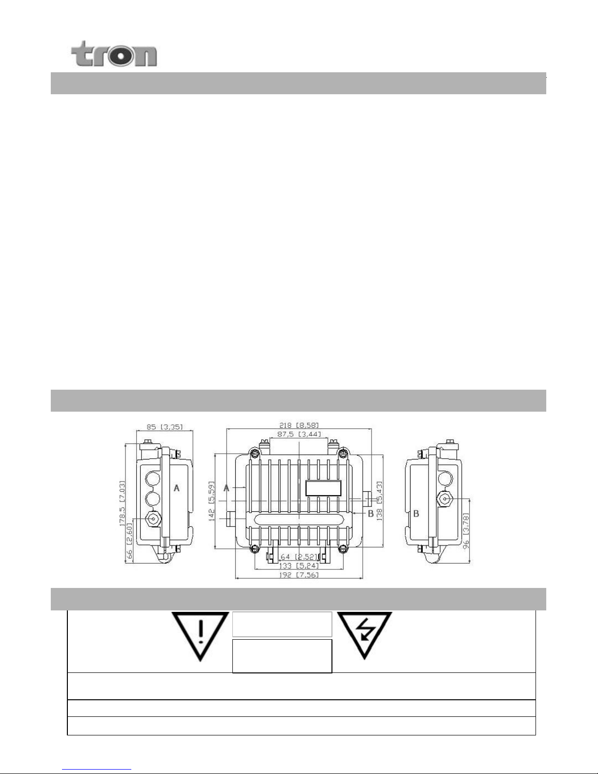
Dimensions
All dimensions are in mm(inch)
Forward Level Setup:
1. Before applying power to the amplifier make sure that the
input level to the amplifier is not too high, or damage to the
amplifier might occur. To be on the safe side, you should set
the input gain control adjustment to minimum gain (fully
counter clockwise) before powering the amplifier.
2. Set the input equalizer control for minimum slope (fully
clockwise) and install a 0dB plug in equalizer (factory installed)
into the midstage equalizer socket.
3. Now apply power to the amplifier and measure the amplifier
output level at the 20dB output test point. If it is very low then
turn the input gain control clockwise to increase the gain until
the desired output level is reached at the highest operating
frequency. Remember that the level measured at the test point
is 20dB lower than the real signal level at the output port.
4. Turn the input equalizer control to adjust the output level to
be flat across the full bandwidth. The input signal level will now
be flat too. Under this condition there will be best CNR across
the full bandwidth.
5. Now install a plug-in equalizer into the midstage equalizer
socket to get as close as possible to the desired output signal
slope. The desired output slope is determined by your system
design. Consult your system planner or your system maps for
this information.
6. Make a final adjustment of the output slope and output level
with the input gain and slope controls. Always adjust the gain
control, then the slope control in that order.
7. If you are having trouble obtaining the expected output
levels then check the input test point to verify that the levels
are as expected at the input of the amplifier.
8. Record the in/out operating levels and mid equalizer option
used in this station on the lid label, and proceed to the reverse
band level setup.
Reverse Level Setup:
1. If the forward amplifier is not set up, stop and do it now. It is
recommended that the forward amplifier be set up first since its
high gain requires extra precautions be taken before powering.
2. A commercially available reverse sweep and balance test
system is recommended for setting up the TLE35128 reverse
amplifier. With this test system the forward output test point will
be used for a reverse signal injection point, and you should start
your set up at the first amplifier out from the node. Follow the
procedure offered in the test system manual.
3. If you don't have a reverse sweep and balance test system
then you will need two people to set up the reverse band, and
they will need to communicate with each other.
4. The procedure is simply explained as follows:
- Reverse signals are all combining to arrive at the node
destination. Therefore the signals should be set up to have
constant levels at each reverse amplifier input.
- Constant input signal levels are achieved by injecting an
XdBmV test signal into the reverse input using the forward
output 20dB test point. Then the reverse amplifier output gain
and slope controls are adjusted to achieve the same XdBmV
input signal level at the following amplifier (or node) input. The
person at the node reports the resulting levels to the person
injecting and adjusting. This gives a unity gain setupfor each
reverse span.
- The person at the node does not have to move to the
adjacent amp each time the setup person moves to the next
amp. This is because the system is being set up for unity gain.
- Remember that the reverse test points and the injection point
are 20dB directional couplers, so your measured levels and
injected levels should be accordingly adjusted.
Basic Setup Procedure
User Manual – TLE35128
 Loading...