

Page 1

LOG SPLITTER
INSTRUCTION MANUAL
Carefully read the instruction manual before you use this machine,
and save this instruction manual for future reference.
MODEL NO.:12232
Page 2

2
1
2
3
4
5
6
7
8
9
10
11
WARNING SYMBOLS
GENERAL SAFETY INSTRUCTIONS
SPECIAL SAFETY INSTRUCTIONS FOR LOG SPLITTER
TECHNICAL SPECIFICATIONS
Technical specifications
Electrical safety
UNPACKING
LOOSE PARTS LIST
FEATURES
ASSEMBLY AND OPERATION
Assembly
Operation
Freeing a jammed log
Replacing hydraulic oil
Sharpening wedge
TROUBLE SHOOTING
EXPLODED VIEW
PARTS LIST
………
……
3-4
4-5
6-7
7-8
7
7-8
9
9
9-10
10-13
10-11
11-12
12
13
13
14
15
16
TABLE OF CONTENTS
Page 3

3
WARNING SYMBOLS
WARNING! Standard graphic symbols are used on all machines in order to ensure complete
safety of all parts of the log splitter. As these symbols are very important, read the information
below attentively.
It is obligatory to read the machine’s use and maintenance manual in full
before using the machine.
It is obligatory to wear safety footwear at all times to provide protection
against the risk of logs accidentally falling on feet.
It is obligatory to at all times to ware gloves which protect the hands
against chips and splinters which may be produced during work.
It is obligatory at all times to wear goggles or a visor which protects the
hands against chips and splinters which may be produced during work.
It is forbidden to remove or tamper with the protection devices and safety
devices.
It is forbidden to stand in the range of action of the machine, apart from
the operator, no other person or animal may be present within a radius of
5 meters from the machine.
Dumping of used oil in the environment is forbidden. The oil must be
disposed of according to current legislation in the country where this
operation is carried out.
Danger of cutting or crushing of the hand: never touch hazardous areas
while the wedge is moving.
Warning: always pay attention to the movement of the log pusher.
Page 4

4
Warning: never remove a log trapped in the wedge with your hands.
Warning: Before carrying out any maintenance operation described in
this manual, disconnect the plug of the machine.
Warning: voltage as indicated on the rating plate.
GENERAL SAFETY INSTRUCTIONS
IMPORTANT! When using electrical tools, the following safety instructions should be observed to
prevent the risk of electric shock, personal injury and fire. Read and observe these instructions
carefully before using the tool.
1. Keep work area clean
Cluttered areas and benches invite
injuries.
2. Consider work area environment
Do not expose power tools to rain. Do not
use power tools in damp or wet locations.
Keep work area well lit. Do not use power
tools near flammable liquids or gases.
3. Guard against electric shock
Prevent body contact with grounded
surfaces (e.g. pipes, radiators, ranges,
refrigerators etc.)
4. Keep children away
Do not let visitors contact tool or extension
cord. All visitors should be kept away from
work area.
5. Store idle tools
When not in use, tools should be stored in
a dry, high or locked-up place, out of the
reach of children.
6. Do not force tool
It will do a better job and operate more
safety at the rate for which it was intended.
7. Use right tool
Do not force small tools or attachments to
do the job of a heavy duty tool. Do not use
tools for other than their intended purpose;
for example do not use a circular saw for
cutting tree limbs or logs.
8. Dress properly
Do not wear loose clothing or jewelry.
They can be caught in moving parts.
Rubber gloves and non-skid footwear are
recommended when working outdoors.
Wear protection hair covering to contain
long hair.
9. Use safety glasses
Also use a dust mask during pulverulent
operations and wear ear protection. If the
noise level exceeds 85 dB (A), ear
protection is obligatory. Indicated noise
levels many be exceeded dependent on
the working environment and the material
to be treated.
10. Use dust extraction
If dust extraction and collection devices
are present on the tool, make sure that
they will be used properly.
Page 5

5
11. Do not abuse cord
Never carry tool by cord or yank it to
disconnect it from wall outlet. Keep cord
from heat, oil and sharp edges.
12. Secure work
Use clamps or a vise to hold the
workpiece. It is safer and it frees both
hands to operate tool.
13. Do not overreach
Keep proper footing and balance at all
times.
14. Maintain tools with care
Keep tools sharp and clean for better and
safer performance. Follow instructions for
lubricating and changing accessories.
Inspect tools cords periodically and, if
damaged, have them repaired by an
authorized service facility.
Inspect extension cords periodically and
replace if damaged. Keep handles dry,
clean and free from oil and grease.
15. Disconnect tools
When not in use, before servicing, and
when changing accessories such as
blades, bits and cutters.
16. Remove adjusting keys and wrenches
Form the habit of checking to see that
keys and adjusting wrenches are removed
from the tool before switching it on.
17. Avoid unintentional starting
Do not carry plugged-in tools with finger
on switch. Be sure that the tool is switched
off before plugging in.
18. Outdoor use extension cords
When tools is used outdoors, use only
extension cords intended for use outdoors
and so marked.
19. Stay alert
Watch what you are doing. Use common
sense. Do not operate tools when you are
tired.
20. Check damaged parts
Before further use of the tool, a guard or
other part that is damaged should be
carefully checked to determine that it will
operate properly and perform its intended
function. Check for alignment of moving
parts, binding of moving parts, breakage of
parts, mounting, and any other conditions
that may affect its operation. A guard or
other part that is damaged should be
properly repaired or replaced by an
authorized service center unless
otherwise indicated elsewhere in the
instruction manual. Do not use tool if
switch does not turn it on and off.
21. Warning
The use of any other accessory or
attachment other than recommended in
the instruction manual may present a risk
of personal injury.
22. Have your tool replaced by an expert
This electric appliance is built in
accordance with the relevant safety rules.
Repair of electric appliances must only be
carried out by experts otherwise it may
cause considerable danger for user.
Store these instructions for future reference
Page 6

6
SPECIAL SAFETY INSTRUCTIONS FOR LOG SPLITTER
1. The log splitter must always be used by
one operator only.
2. Nobody must be allowed to use the log
splitter unless they have read the
instruction manual and have been
instructed in the regulations to follow for
correct and safe use.
3. The machine must be used by adults only.
Use of the log splitter by apprentices of not
less than 16 years of age must be
supervised by an adult authorized to use
the machine.
4. Never wear loose, unbuttoned clothing
which may become trapped in moving
parts.
5. Position the machine on a support surface
of 60-75 cm height, free from any objects
that could prevent complete freedom of
movement for the operator while working.
The surface must be perfectly leveled to
prevent the machine from falling during
operation.
6. it is prohibited to work with the machine on
the ground. This is not only an
uncomfortable working position but it it can
also be dangerous because the operator
has to bring his face close to the machine,
and thus risks being struck by chips or
debris.
7. Check that the logs to be split are free
from nails or wire, which may fly up or
damage the machine, the ends of the logs
must be cut square, branches must be cut
off flush with the trunk.
8. Never try to split logs larger than those
indicated in the technical specifications.
This could be dangerous and may
damage the machine.
9. Break wood in the direction of the grain,
do not place wood across the log splitter
and leave it in that position for splitting; it
may be dangerous and may seriously
damage the machine.
10. Never attempt to cut two logs at once, one
may fly up and hit you.
11. If the log moves away from the blade,
retract the ram or the blade and turn the
log through 90
0
.
12. Do not attempt to load the log in the log
splitter while the ram is in motion, you
could get trapped and injured.
13. Keep your hands well away from any splits
and cracks which open in the log; these
may close suddenly and crush or
amputate your fingers.
14. Never force the log splitter for more than 5
seconds keeping the cylinder under
pressure in the attempt to split excessively
hard wood. After this time interval, the oil
under pressure is overheated and the
machine could be damaged. It is thus
better to stop and rotate the log by 90
0
to
see whether it can be split in a different
position. In any case, if you are not able to
split the log, this means that its hardness
exceeds the capacity of the machine and
thus that log should be discarded so as
not to damage the lop splitter.
15. Do not force the blade by pushing the log
on the upper part, as this can cause the
blade to break or damage the body of the
machine. Always set the log on the guides.
16. Never leave the machine unattended
while it is running. If you leave the
machine, even for a short time, remove
the power supply or any possible cause of
accidental start-up.
17. The log splitter must never be used by an
operator who is under the influence of
alcohol, drugs, medicines, or who is tired.
A clear mind is essential for safety.
18. Never request the assistance of another
Page 7

7
person to help you remove a jammed log.
19. Do not use machines with electric motor if
natural gas, petrol fumes or other
inflammable vapours are present.
20. Check that the electric circuit is
adequately protected and that it
corresponds with the power, voltage and
frequency of the motor, check that there is
a ground connection, and a regulation
differential switch upstream.
21. Never open the switch box on the motor.
Should this be necessary, contact a
qualified electrician.
22. Make sure that the machine and the cable
never come in contact with water.
23. Treat the power cable with care, do not
attempt to move the machine by pulling
the cable, do not yank the cable to unplug
it; keep the cable away from excessive
heat, oil and sharp objects.
24. Never leave the machine unattended with
the power supply “on”, also disconnect the
power cable when not in use, when
carrying out maintenance work, when
changing attachment or moving the
machine.
TECHNICAL SPECIFICATIONS
Technical specifications
Voltage
Frequency
Power input
No load speed
Insulation class
Protection degree
Max. splitting force (tons)
Max. cylinder travel
Diameter of cylinder
Log Capacity
Diameter
Length
Hydraulic oil capacity (Lt.)
Net weight
Gross weight
L
pa
(sound pressure level)
L
wa
(sound power level)
230V~
50Hz
1500W
2,950min-1
Class B
IP 54
5
390mm
55mm
50-250mm
520mm
2.8
40kgs
42kgs
66.3 dB(A)
79.3dB(A)
Electrical Safety
WARNING! Always check that the power
supply corresponds to the voltage on the
rating plate.
WARNING! Connect the main leads to a
standard 230V±10% (50Hz±1Hz) electrical
supply which has protection devices of
under-voltage, over-voltage, over-current
as well as a residual current device (RCD)
which maximum residual current rated at
30mA.
Page 8

8
Replacing cables or plugs
Immediately throw away old cables or plugs
when they have been replaced by new ones. It
is dangerous to insert the plug of a loose cable
in the wall outlet.
Using extension cables
1. As a supply for this machine always use
an unloaded line and/or extension with
conductor of at least 2.5mm
2
and
protected with a 20A fuse. Be sure that
this extension cable is not longer than 10
meters. Excessively long cables or
inadequate section can cause voltage
drops that prevent motor from developing
its full power.
2. Only connect your machine and/or
extension cable to an earthed electricity
mains.
3. This machine can be switched to the
single-phase network (230V/50Hz), if you
are in doubt about the earth of the
electricity provisions, consult an electrician
first.
Grounding
In the event of an electrical short circuit,
grounding reduces the risk of electric shock by
providing a path of least resistance to disperse
electric current. This machine is equipped with
a power cord having a equipment-grounding
prong
1. Reduce the risk of electrocution by
keeping all connections dry and off the
ground. Do not touch plugs with wet hands.
Failure to follow these warning could result
in serious injuries.
2. This machine must have a ground prong
in the plug to help ensure that it is
grounded. Do not remove ground prong
from plug to fit into a two-pronged outlet! If
the plug will not fit the outlet, have the
proper outlet installed by a qualified
electrician.
UNPACKING
WARNING! To prevent accidental starting that
could cause possible serious personal injury,
assemble all parts to your log splitter before
connecting it to power supply. Log splitter
should never be connected to power supply
when you are assembling parts, making
adjustments, installing or removing drill bit, or
when not in use.
l Carefully remove all parts from the carton
and place the log splitter on a level work
surface of the height not less than 60cm.
Separate and check against the list of
loose parts.
WARNING! If any parts are missing, do not
operate this machine until the missing parts
are replaced. Failure to do so could result in
serious personal injury.
l Do not discard the packing materials until
you have carefully inspected the log
splitter, identified all parts, and
satisfactorily operated you new log
splitter.
Note: If any parts are damaged or missing, do
not attempt to plug in the power cord and turn
the switch on until the damaged or missing
parts are obtained and are installed correctly.
Page 9
9
LOOSE PARTS LIST
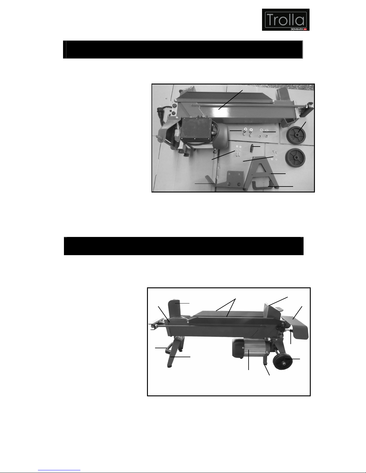
Check all loose parts from the box with the list below. Assemble according to the instruction on the
following pages
1. Machine body assembly
2. Rolling wheels
3. Supporting leg
4. Safety guard for
ZHB hydraulic control
lever
5. Rubber knob for
ZHB hydraulic control
lever
6. 2 sets of screws, elastic
washers and flat washers for
assembling safety guard
7. 2 sets of Nuts and flat washers for assembling wheels
8. 2 sets of bolts, elastic washers and flat washers for assembling carrying handle
9. 2 sets of bolts, elastic washers and flat washers for assembling supporting leg
FEATURES
1. Before attempting to use, familiarize yourself with all the operating features and safety
requirements of your log splitter.
1. Wedge
2. Oil tank
3. Carrying handle
4. Supporting leg
5. Motor w/push switch
& circuit breaker
6. Rubber feet
7. Rolling wheel
8. ZHB hydraulic
control lever
9. Safety guard for
hydraulic control lever
10. Log pusher
11. Log retention brackets
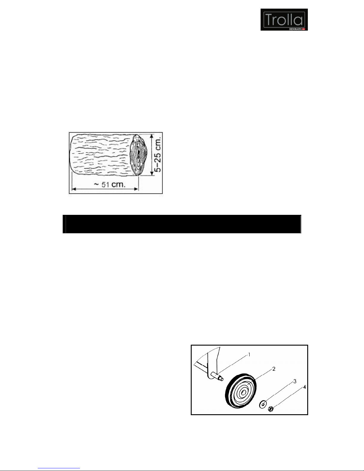
2. Size of the logs to be split
The figure 1 shows the maximum log sizes
that can be split.
The diameter of the log is indicative: a small
log can be difficult to split if it has knots or a
particularly tough fiber. On the other hand, if
1
2
3
5
4
6
7
8
9
10
10. Carring handle
1
2
3
4
5
6
7
8
9
10
11
Page 10
10
the wood has regular fibers it is not difficult to
split logs with diameter greater than the
maximum shown in fig. 1. It is important not
to insist when the log does not split on the
first attempt, as the pump may be damaged
by the overheating of the oil when the
machine is made to work under the
maximum stress in the attempt to split
excessively hard wood.
Fig. 1
3. Recommended oils
We recommend use of the following oils for
the hydraulic cylinder.
SHELL TELLUS T22
ARAL VITAM GF22
SP ENERGOL HCP22
MOBILE DTE 11 OR equivalent
DO NOT USE OTHER GRADE OILS
4. Application conditions
This log splitter is a home use model. It is
designed for operating under ambient
temperature between +5
0
C and 400C and for
installation at altitudes no more than 1000mm
above M.S.L. The surrounding humidity
should less than 50% at 40
0
C. It can be stored
or transported under ambient temperatures
between -25
0
C and 550C.
ASSEMBLY AND OPERATION
Warning! For your own safety, do not connect the log splitter to the power source until the
machine is completely assembled and you read and understand the entire instruction
manual.
Warning! For your own safety, never forget to bolt the support leg to the log splitter, lift the
log splitter by the handles at both ends and place it on a 60-75cm high, stable, flat and level
work surface.
Warning! Never use the log splitter if it is not in perfect order or if it needs servicing. Before
starting work, check correct functioning of all the safety devices (ZHB, push button).
Assembly
1. Before operating the log splitter, it is
necessary to fit the rolling wheel (2) Fig. 2,
on supporting shaft (1) as shown. Insert
the wheels on the shaft, block it using the
washer (3), and fasten by the lock nut (4).
2. Assemble the supporting leg on the
machine body, use the two bolts, elastic
washers and flat washers to fasten the
supporting leg on the machine body.
Fig. 2
Page 11
11
3. Use two screws, elastic washers and flat
washers to fasten the safety guard on the
supporting bracket to protect the ZHB
hydraulic control lever.
4. Turn the rubber knob onto the ZHB
hydraulic control lever for comfortable
operation.
Operation
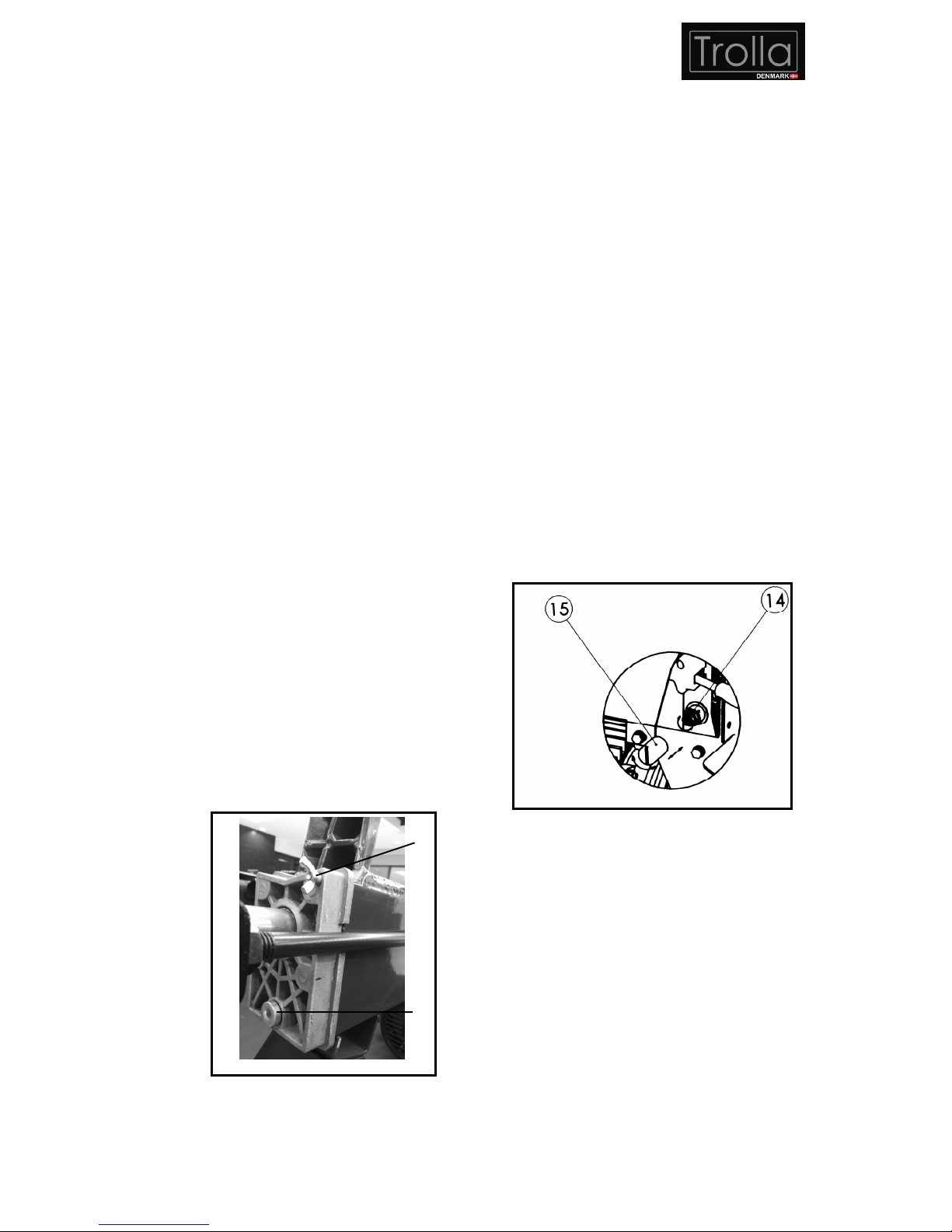
Warning! Before operating the log splitter,
the Bleed Screw (13) Fig. 3, should be
loosened by some rotations until air can go
in and out of the oil tank smoothly.
Air flow thru the Bleed Screw hole should
be detectable while the log splitter is under
operations.
Before moving the log splitter, make sure
the Bleed Screw is tightened to avoid oil
leaking from this point.
FAILED TO LOOSEN THE BLEED SCREW
WILL KEEP THE SEALED AIR IN
HYDRAULIC SYSTEM BEING
COMPRESSED AFTER BEING
DECOMPRESSED. SUCH CONTINUOUS
AIR COMPRESSION AND
DECOMPRESSION WILL BLOW OUT THE
SEALS OF THE HYDRAULIC SYSTEM AND
CAUSE PERMANENT DAMAGE TO THE
LOG SPLITTER.
Fig. 3
DO NOT ADJUST THE MAX PRESSURE
LITITING SCREW (14) IN FIG. 4!
Max pressure was set before the log
splitter ex work and the max pressure
limiting screw is tightened to ensure the
log splitter works under pressure no more
than 4 tons. The setting was done by
qualified mechanic with professional
instruments.
Unauthorized resetting will cause the
hydraulic pump fail to output enough
splitting pressure or RESULT IN SERIOUS
INJURY AS WELL AS DAMAGE TO THE
MACHINE.
The max pressure limiting screw is
protected by a plastic cap (15) as shown in
Fig. 4, and never to loose and adjust it.
Fig. 4
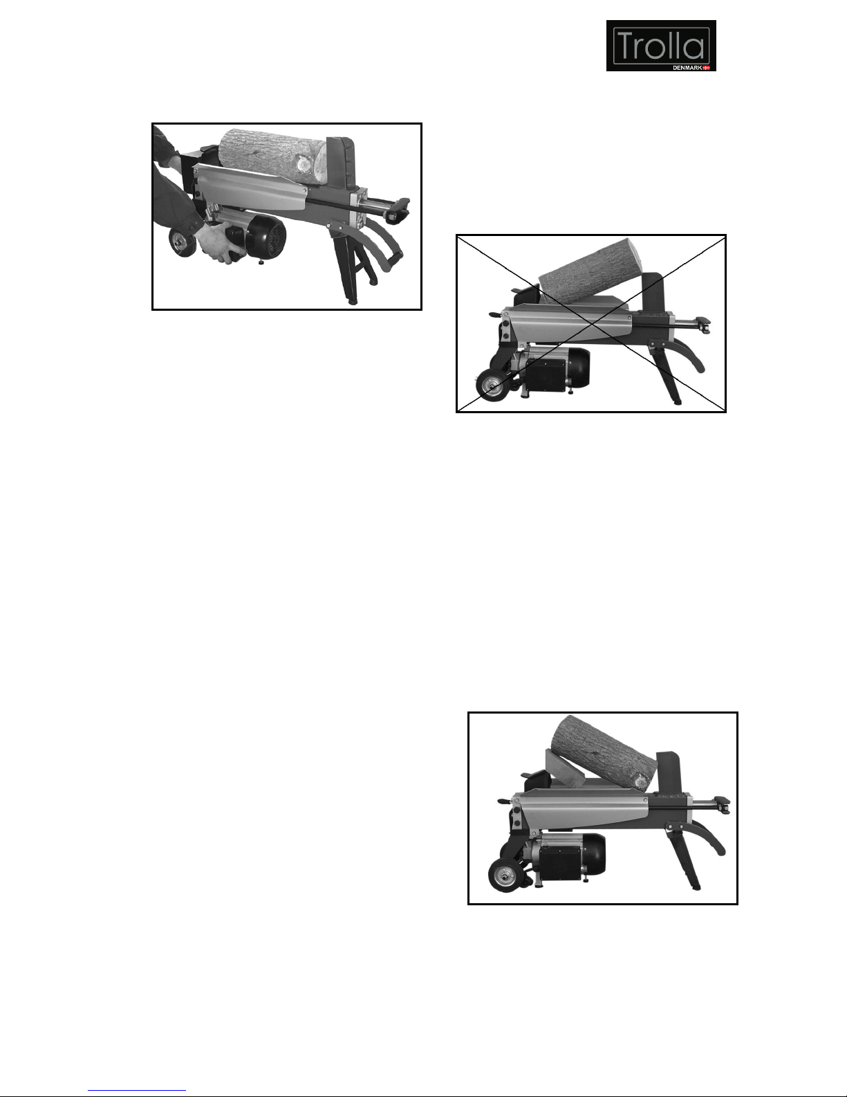
This log splitter is equipped with “ZHB” control
system that requires to be operated by both
hands of the user – left hand controls the
hydraulic control lever while right hand
controls the pushbutton switch as shown in Fig.
5. The log splitter will freeze upon absence of
either hand. Only after both hands release the
controls, the log pusher starts to return
backward to the starting position.
Never force the log splitter for more than 5
seconds by keeping pressure on it to split
13
12
Page 12
12
excessively hard wood.
Fig. 5
After this time interval, the oil under pressure
will be overheated and the machine could be
damaged. For such extremely hard log, rotate
it by 90
0
to see whether it can be split in a
different direction. In any case, if you are not
able to split the log, this means that its
hardness exceeds the capacity of the machine
and thus that log should be discarded to
protect the log splitter.
NOTE: During operation, the metal part
connected to the motor remains cold or in any
case reaches a temperature only slightly
higher than the ambient temperature. After
several hours of use with particularly difficult
wood, the pump may become very hot. This is
not a dangerous situation for the machine,
which returns to full functioning capacity after
being cooled. On the other hand, it is very
important not to cause overheating of the oil,
and thus the pump, by forcing the machine in
an attempt to split logs that exceed the
capacity of the machine.
Always set logs firmly on the log retaining
plates and work table. Make sure logs will
not twist, rock or slip while being split. Do
not force the blade by splitting the log on
the upper part. This will break the blade or
damage the machine.
Break log in the direction of its grown grain. Do
not place log across the log splitter for splitting.
It may be dangerous and may seriously
damage the machine.
Do not attempt to split 2 pieces of logs at the
same time. One of them may fly up and hit
you.
Fig. 6
Freeing a jammed log
1. Release both controls.
2. After the log pusher moves back and
completely stops at its starting position,
insert a wedge wood under the jammed
log.
3. Start the log splitter to push the wedge
wood to go completely under the jammed
one.
4. Repeat above procedure with sharper
slope wedge woods until the log is
completely free.
Fig. 7
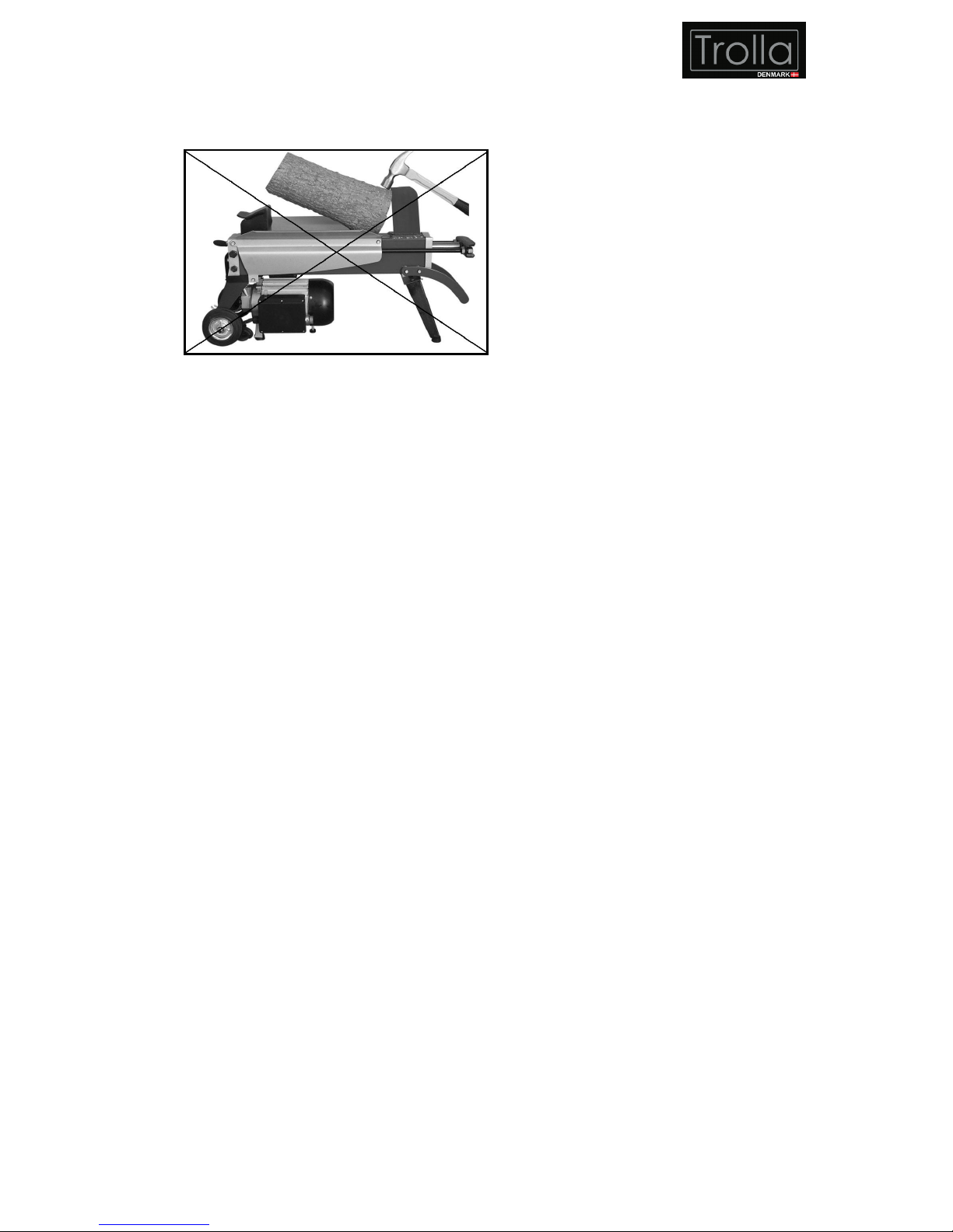
Do not try to knock the jammed log off.
Knocking will damaged the machine or
Page 13
13
may launch the log and cause accident.
Fig. 8
Replacing hydraulic oil
Replace the hydraulic oil in the log splitter after
every 150 hours of use. Take following steps
to replace it.
1. Make sure all moving parts stops and the
log splitter is unplugged.
2. Unscrew oil drain bolt with dipstick to
remove it.
3. Turn the log splitter on the motor side over
an 3 liters capacity container to drain the
hydraulic oil off.
4. Turn the log splitter on the support leg
side.
5. Refill fresh hydraulic oil at the volume as
per the hydraulic oil capacity of a particular
model indicated in the specifications table.
6. Clean the surface of Dipstick on the oil
drain bolt and put it back into the oil tank
while keep the log splitter vertically.
7. Make sure the level of the refilled oil is just
between 2 grooves around the dipstick.
8. Clean the oil drain bolt before thread them
back. Make sure they are tightened to
avoid leakage before placing the log
splitter horizontally.
Periodically check oil level to ensure it is
between 2 grooves around the dipstick.
Upon lower oil level, oil refilling is required.
Warning: Never mix oil with general waste!
Used oil must be disposed of according to
current regulations in the country where
the machine is used.
Sharpening the wedge
After using the log splitter for some time,
sharpen the wedge of the log splitter using a
fine-toothed file and smooth any burrs or
crushed area along the cutting edge.
Page 14

14
TROUBLE SHOOTING
PROBLEM PROBABLE CAUSE REMEDY SUGGESTED
Motor stops
starting
Overload protection device disengaged to
protect the log splitter from being damaged
Let motor cool down, and push the
button of the overload protection
device to re-start the motor
Log is improperly positioned Refer to “Log splitter operation”
section for perfect log loading
The sizes or hardness of the log exceeds
the capacity of the machine
Reduce the log size before splitting
it on the log splitter
Wedge cutting edge is blunt Refer to “Sharpening
wedge“ section to sharpen the
cutting edge.
Oil leaks Locate leak(s) and contact the
dealer
Fails to split
logs
Unauthorized adjustment was made on
Max. Pressure Limiting Screw. Lower
max pressure rating was set.
Contact the dealer
The log pusher
moves jerkily,
taking
unfamiliar
noise or
vibrating a lot
Lack of hydraulic oil and excessive air in
the hydraulic system
Check oil level for possible oil
refilling. Contact the dealer.
Air sealed in hydraulic system while
operating
Loosen bleed screw by some
rotations before operating the log
splitter
Bleed screw is not tightened before
moving the log splitter
Tight the bleed screw up before
moving the log splitter
Oil drain bolt with dipstick is not tight. Tighten the oil drain bolt with
dipstick
Oil leaks
around
cylinder ram or
from other
points
Hydraulic control valve assembly and/or
seal(s) worn.
Contact the dealer
Page 15
15
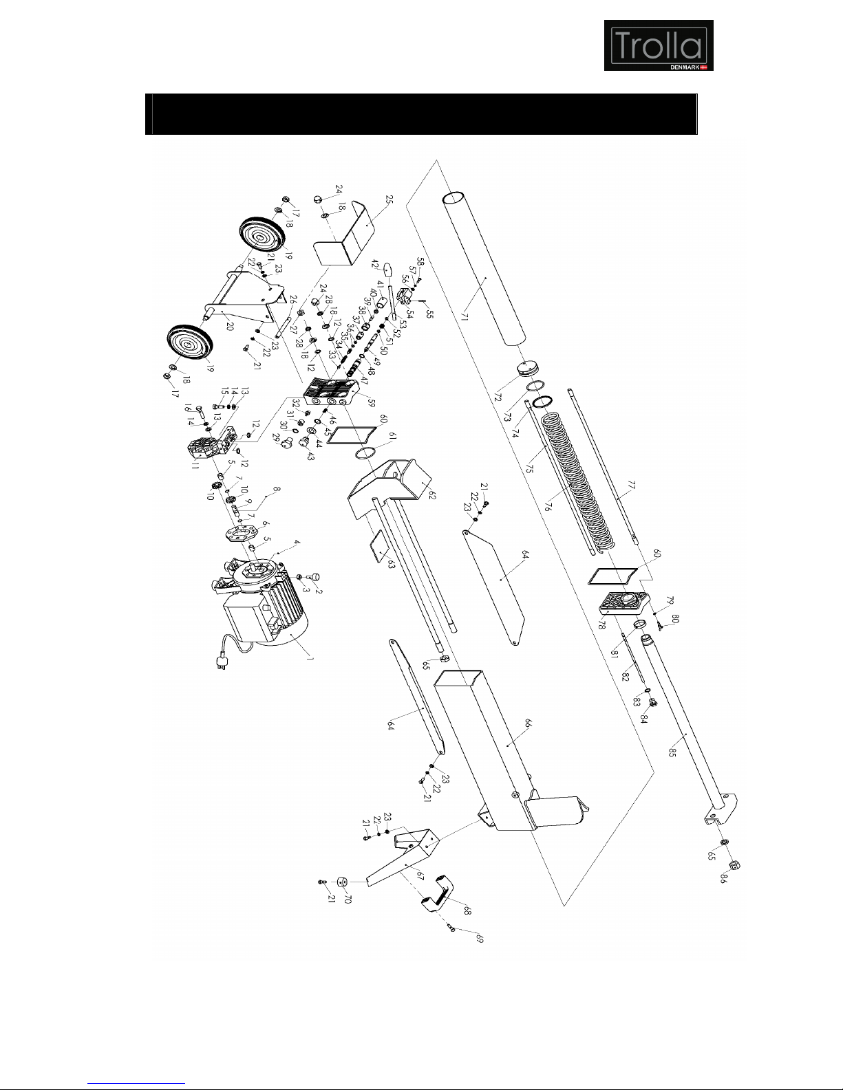
EXPLODED VIEW
Page 16
16
PARTS LIST
Part No.
Description
Q’ty
Part No.
Description
Q’ty
1
Motor
1 44
Copper washer 14
1
2
Rubber pad
1 45 O-
ring 14×1.8G
1
3 Nut M8 1 46
Spring
Ⅱ
1
4
Pin φ2.5×4
1 47
Controlling valve
(GS)
1
5 Axle sleeve 3 48 O-
ring 11.2×1.8G
5
6
Casting iron plate
1 49
Controlling shaft
1
7
Steel ring 10
2 50
Sealing ring 5.6×1.8G
1
8
Steel ballφ2.5
1 51
Spring
Ⅰ
1
9 Gear shaft 1 52 E-
ring
1
10
Gear
2 53 Handle 1
11
Gear pump cover
1 54
Fixing bracket
1
12 O-
ring 9.5×2.65G
6 55
Elastic pin 3×20
1
13 Flat washer 8 9 56 Flat washer 5 2
14 Elastic washer 8 9 57 Elastic washer 5 2
15 Bolt M8×30 3 58 Screw M5×16 2
16 Bolt M8×55 6 59
Front cover
1
17 Lockin
g nut M10
2 60
Sealing ring
2
18 Flat washer 10 6 61 O-
ring 48.7×3.55G
1
19
Rolling wheel
2 62
Log pusher
1
20
Rolling wheel bracket
1 63
Plastic pad
2
21 Bolt M6×12 18 64
Log retention bracket
2
22 Elastic washer 6 18 65 Nut M14 4
23 Flat washer 6 18 66 Oil tank 1
24 Nut M10 2 67
Supporting leg
1
25
Safety cover
1 68
Carrying handle
1
26
Support shaft
1 69 Bolt M6×25 2
27 Nut M10 2 70 Rubber foot 4
28 Elastic washer 10 4 71
Cylinder tube
1
29 Hex-bolt M14×20 1 72 Piston 1
30 O-
ring 11.8×1.8G
1 73 O-
ring 43.7×3.55G
1
31 Screw 1 74
Plastic ring
1
32 Oil valve 1 75 2-
head rod (A)
2
33 Cone valve 1 76
Spring
1
34
Adjusting spring
1 77 2-
head rod (B)
2
35 Short shaft 1 78
Rear cover
1
36 O-
ring 4.87×1.8G
2 79 O-
ring 3.6×1.8G
1
37 Tube for short shaft 1 80 Screw M4×16 1
38 Nut 1 81
Dust proof ring FC3038×5
1
39 Screw M6×20 1 82 Oil level stick 1
40 Nut M6 1 83 O-
ring 11.2×2.65G
1
41
Plastic cap
1 84
Oil level stick cap
1
42 Knob 1 85 Piston rod 1
43 Position bolt 1 86 Nut M10 2
 Loading...