

Page 1

P5593.1600 Rev A 1
GasHawk TX7000 User Manual
www.trolex.com
TX7000
GasHawk – Personal Gas Monitor
Page 2

2 P5593.1600 Rev A
www.trolex.com
Page 3

GasHawk TX7000 User Manual
P5593.1600 Rev B 3
GasHawk TX7000
Contents
1. Product Overview 5
1.1 Main features 5
1.2 Functions 6
1.3 Accessories 6
1.4 Credentials 6
2. Technical Information 7
3. Preparation 10
3.1 Contents 10
3.2 Charge the battery 11
3.3 Change the battery 11
4. Controls and Indicators 12
4.1 Layout 12
4.2 Main button functions 12
4.3 Short-cut button functions 12
5. Operation 13
5.1 Menu map 13
5.2 ON/OFF 14
5.3 Main display 15
5.3.1 Alarms and messages 16
5.3.2 System and diagnostic alerts 17
5.4 Pump operation 18
6. Facilities 19
6.1 Enter a password 19
6.2 Zero in clean air 21
6.3 Bump test 22
6.4 Extended bump test 23
6.5 Calibrate 24
6.6 Zero CO2 in N
2
26
7. View 27
7.1 About 27
7.2 Peak 27
7.3 TWA 27
7.4 STEL 27
7.5 Alarm settings 28
7.6 Test gas values 29
7.7 Bump and calibration diary 29
7.8 Quick guide 29
8. Setup 30
8.1 Preferences 30
8.1.1 Continuous ON mode 31
8.1.2 Main display 31
8.1.3 Confidence beep 31
8.1.4 Confidence flash 31
8.1.5 Disable vibrator 31
8.1.6 Alarm latch 31
8.1.7 Invert display 31
8.1.8 Require password 31
8.1.9 Change password 32
8.1.10 Time. Date 32
8.1.11 Language 32
8.1.12 STEL period 32
8.1.13 Auto zero on start-up 32
8.1.14 LEL units 33
8.1.15 CO2 Units 33
8.1.16 Factory default 33
8.1.17 LCD power save 33
www.trolex.com
Page 4

4 P5593.1600 Rev B
GasHawk TX7000
Contents
8.2 Calibration Mode 34
8.2.1 Mandate bump test 34
8.2.2 Mandate calibration if fail 34
8.2.3 Mandate calibration when due 34
8.2.4 Test gas values 34
8.2.5 Calibration intervals 35
8.2.6 Bump test intervals 35
8.3 CH4 LEL Alarms 36
8.4 O2 Alarms 36
8.5 CO Alarms 36
8.6 H2S Alarms 36
8.7 Reset LEL alarms 36
9. Data Log & Communications 37
10. Maintenance 37
10.1 Service and calibration 37
10.2 Annual safety check 37
11. Precautions 38
11.1 Operating safety 38
11.2 Hazardous areas 38
11.3 Evacuation 38
11.4 Battery charging 38
11.5 Flammable gas sensors 38
11.6 Toxic gas sensors 39
11.7 Service and repair 39
11.8 Disposal 40
11.9 Contamination 40
11.10 Aggressive chemicals 40
11.11 Atmospheric pressure variations 40
11.12 Condensation 40
12. Accessories 41
13. Certification 42
www.trolex.com
Page 5
GasHawk TX7000 User Manual
P5593.1600 Rev B 5
1. Product Overview
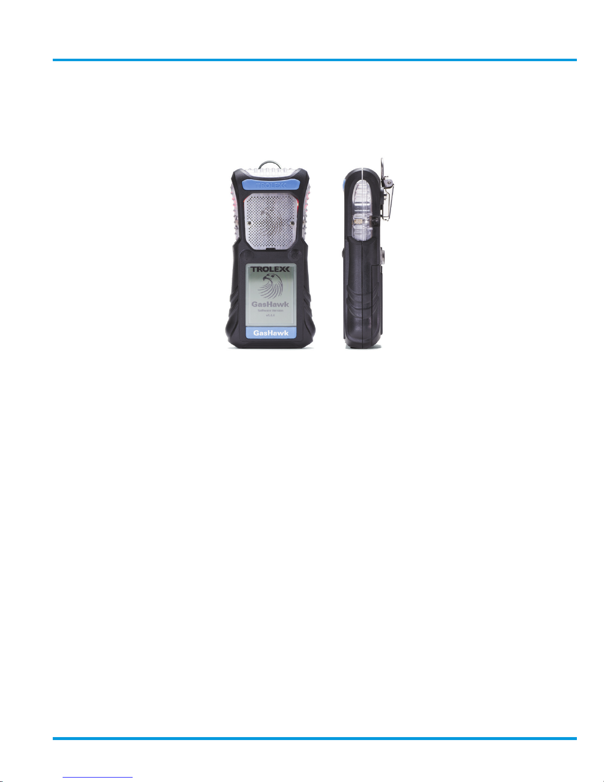
GasHawk is a hand-held personal gas monitor for safety protection of personnel working in
potentially hazardous areas.
1.1 Main Features
• Impact resistant construction with resilient shockproof housing sealed to IP67 ingress protection
• Fully sealed gas ports and sounder
• Rechargeable Prismatic Lithium Ion battery with automatic wireless charging
• Hot–swap intrinsically safe battery pack which can be changed in the hazardous area
• Two large push-buttons for intuitive control of all field functions
• Up to six gas sensors in a choice of combinations of toxic and flammable gases
• High intensity wide-angle LED alarm warning indicator and loud audible alarm both
modulated to signify alarm severity
• Infra red, non-contact data transfer communications
• Option with integrated remote sampling pump for confined space entry alert
• Large high definition illuminated LCD display providing a bright, clear readout and intuitive
message interface
• HawkEye PC application for data log download and setup spreadsheet
• Active atmospheric pressure compensation
• Up to 64 days automatic data logging
www.trolex.com
Page 6

6 P5593.1600 Rev B
1.2 Functions
• Spot reading or continuous reading mode
• Auto Zero
• Two independent adjustable set point gas alarms for HIGH and LOW with function
selection for each channel
• Peak signal retention
• Automatic STEL and TWA calculations as defined by EH40 with alarm warnings
• Continuous data logging with time and date stamp and event record
• Time of day clock and calendar with display
• Language options to specification
• Automatic prompts for bump test and calibration due
• Password protected setup controls
• Active battery management for continuous charging, contents display and condition
warning alarms
• Pump function alarms
• Confidence beep and flash
1.3 Accessories
• Wireless battery charger powered from a universal voltage mains power supply
• Multi-way charging stations in vertical or horizontal formats
• Bump test station with gas application button for convenient and rapid gas response
testing – can be used in the hazardous area subject to local regulations
• Universal docking station – all support functions in one convenient package; bump test,
calibration wireless charging and infrared data link for PC implemented setup or data log
download
• Complete range of carrying accessories
1.4 Credentials
• International certifications for use in underground mining and industrial hazardous areas
with EMC protection
www.trolex.com
Page 7

GasHawk TX7000 User Manual
P5593.1600 Rev B 7
2. Technical Information
Operating temperature: -20°C to +50°C
Storage temperature: -20°C to +60°C
Humidity: 0 to 95% RH (non-condensing)
Pressure: 800 mbar to 1100 mbar ambient
Housing: Moulded polymer with integral resilient over-mould
Ingress protection: IP67
Nett weight: 350g, 375g with pump
Dimensions: L156 x W75 x H35
Battery: Sealed prismatic Lithium Ion with wireless charging. Hot-swap
intrinsically safe battery pack can be changed in the hazardous
area.
Battery run time: 168 hours with LED IR and electrochemical cells installed
20 hours with catalytic and electrochemical sensor installed
Battery charge time: 6 hours with automatic charge management for continuous
standby charging
Display: 52mm x 42mm high definition graphic LCD with automatic
power-down and LED rear illumination
Controls: Two sealed push-buttons for all field functions, profiled for
operation with gloved hands
Alarms: • Flashing wide-angle LED indicator and audible alarm,
modulated indication of gas risk present
• Audible alarm 95dB at 300mm
• Low battery warning
• Confidence tone and flash at user defined interval with green
flashing LED indicator
• Calibration and bump test due prompt
• STEL and TWA preset alarms
Data functions:
• Automatic data log of sensor signals, alarm events and
parameter changes; 30 to 64 days dependant on configuration
• Real-time clock and display showing HH:MM
• Language options to user specification
• Peak signal retention for each gas sensor
• STEL and TWA auto calculation with prescribed alarm level in
accordance with EH40 standards
Pressure compensation • Active atmospheric pressure compensation for the O2, CO2
and infrared CH4 sensors
T90 response time • 30 seconds nominal (dependent on the gas type)
www.trolex.com
Page 8

8 P5593.1600 Rev B
2. Technical Information
Setup functions: • Calibrate ZERO and SPAN
• Alarm level 1 and alarm level 2
• Continuous ON mode selection
• Password security protection
• Display invert
• Auto ZERO enable
• Gas units of display
• Calibration alert interval
• Bump test alert interval
• Disable a gas sensor
• Main display format
• Confidence alert
• Date and time
• Language options
• STEL/TWA function
• LEL equivalence
PC Communications: HawkEye PC application for USB data exchange when the
GasHawk is loaded into a TX7005 Universal Docking Station.
• GasHawk cloning
• Data log download
• Historical data analysis
• Service records
• Printout requests
Diagnostics: • Individual gas sensor display
• Calibration due indicator
• Bump test due indicator with days remaining
• Service due indicator with days remaining
• Battery power remaining
• Alarm test
• Test gas report
• Sensor fault
• LED fault
• Audible fault
• Vibration fault
• Pump fail
www.trolex.com
Page 9
GasHawk TX7000 User Manual
P5593.1600 Rev B 9
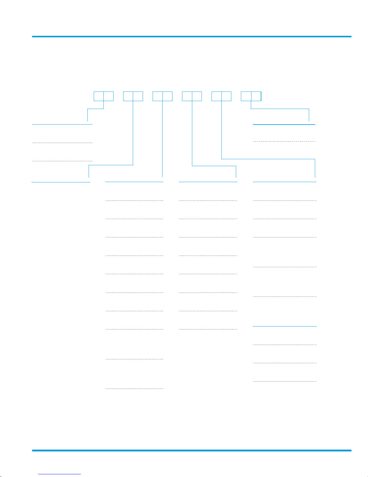
TX7000 . . . . . .
ATEX/IECEx Group I 19
ATEX/IECEx Group II 20
CH45% v/v IR 04
CH4 100% LEL (4,4%) IR 05
CH4100% LEL (5%) IR 06
CH4
+
CO
2
5% v/v
5% v/v
07
CH4
+
CO
2
100% LEL (4,4%)
5% v/v
08
CH4
+
CO
2
100% LEL (5%)
5% v/v
09
CH45% v/v 10
CH4100% LEL (4.4%) 11
CH4100% LEL (5%) 12
No pump 00
With pump 01
O
2
25% v/v 01
CO 500 ppm 01
CO 2000 ppm 20
CL210 ppm 02
H2 1000 ppm 03
H2S 50 ppm 04
NO 250 ppm 05
NO220 ppm 06
SO220 ppm 07
CO
+
H2S
500 ppm
200 ppm
08
H2S
+
SO
2
100 ppm
20 ppm
09
SENSOR A SENSOR CSENSOR B SENSOR D
CO 500 ppm 01
CO 2000 ppm 20
CL210 ppm 02
H2 1000 ppm 03
H2S 50 ppm 04
NO 250 ppm 05
NO220 ppm 06
SO220 ppm 07
Product options:
www.trolex.com
Page 10
10 P5593.1600 Rev B
3. Preparation
3.1 Contents
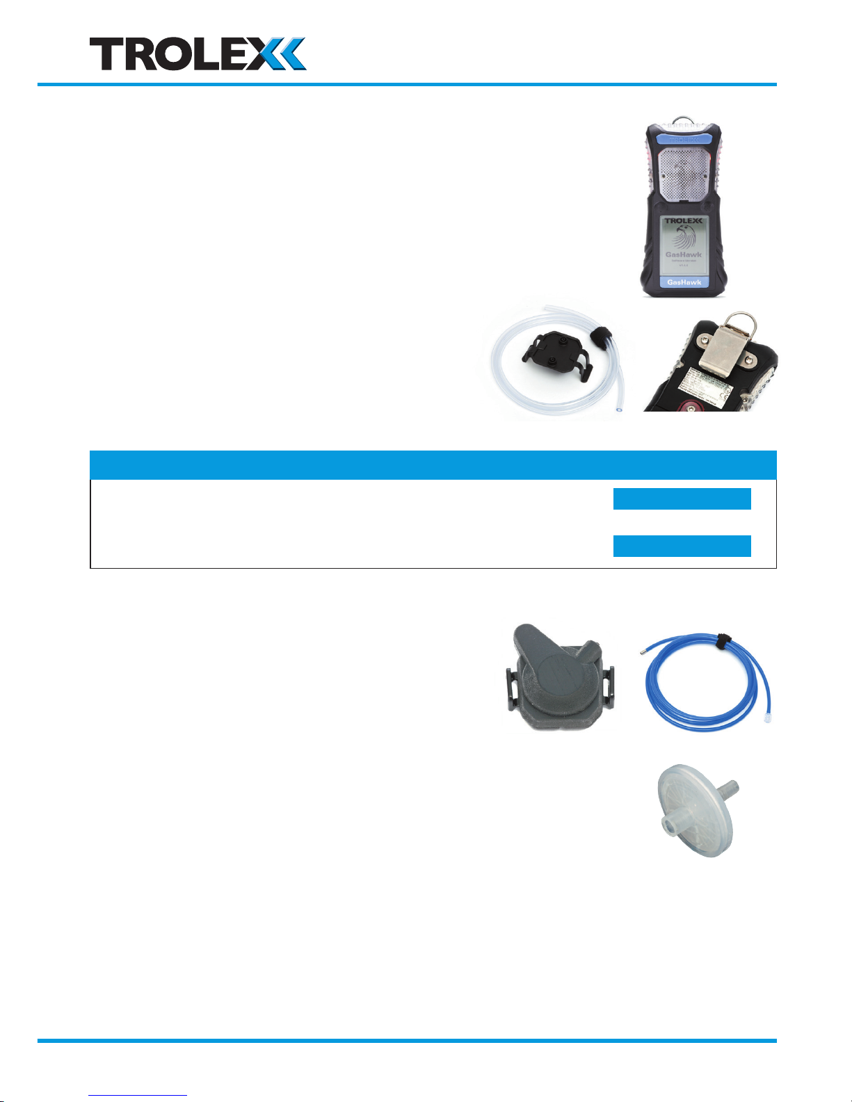
No Pump TX7000.xx.xx.xx.xx.xx.00
1 x GasHawk instrument
Complete with battery pack
1x Test gas hood with flexible tube – 1m long
1x Workwear clip
1x User manual
No Pump TX7000.xx.xx.xx.xx.xx.01
Additional items included
1x Pump hood complete
1x 3m long flexible FKM suction tube with fittings
1x Hydrophobic line filter
Checkpoint
• Check that the gas sensor make-up of the instrument is
correct for the gas risks anticipated.
• View the gas sensor make-up in the MAIN DISPLAY
when the instrument is switched on.
Section 5.3 >>
Section 2 >>
www.trolex.com
Page 11
GasHawk TX7000 User Manual
P5593.1600 Rev B 11
3.2 Charge the battery
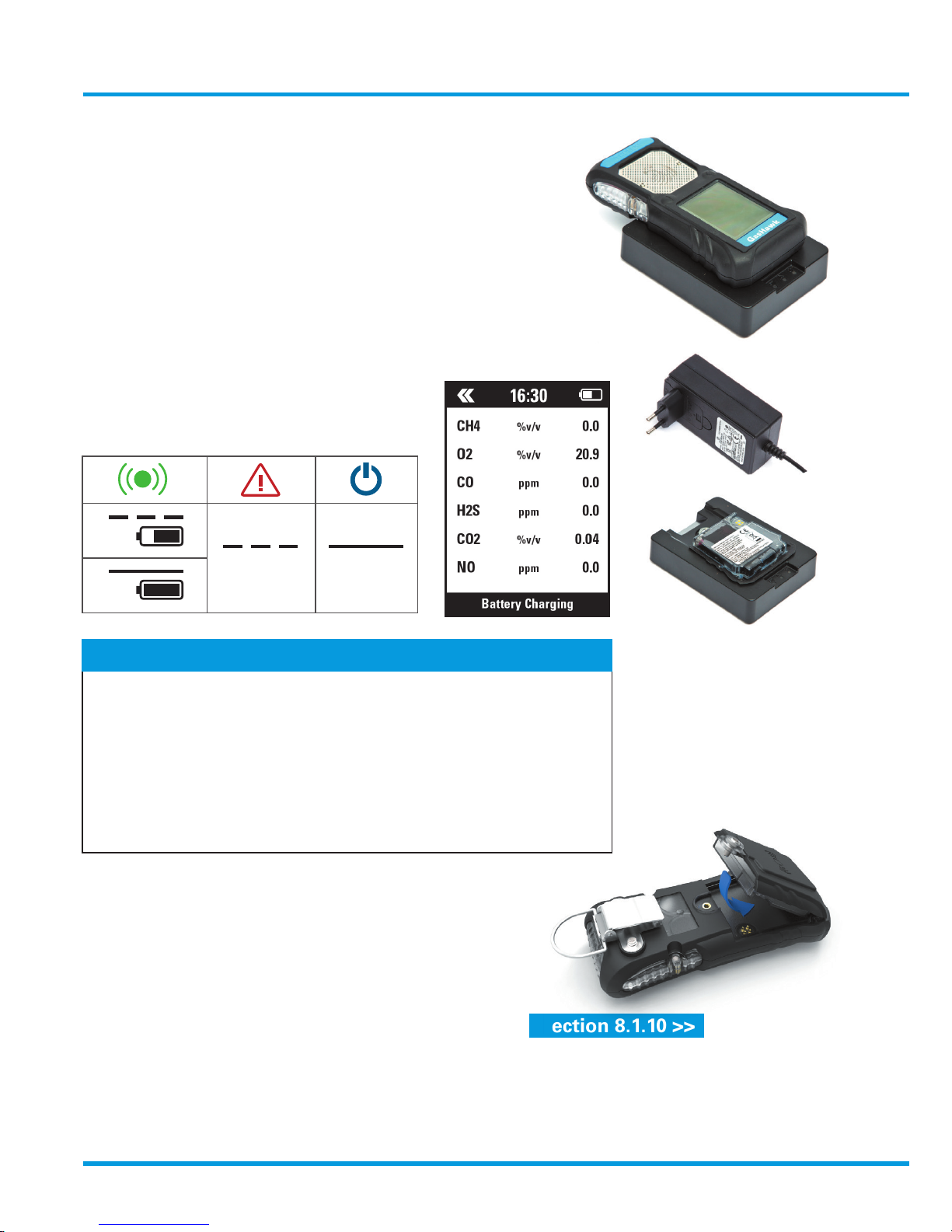
Charger type: • TX7001 Charger
• TX7005 Universal Docking Station
Power supply: Universal mains power supply
90 – 265V AC 50/60Hz 250mA
Initial charge: 10 hours
Routine charge: 6 hours
Charge cycles: 500 approx
3.3 Change the battery
Checkpoint
• Charge periodically to maintain battery condition
• GasHawk may be docked on permanent charge standby
• Only Trolex GasHawk chargers may be used
• Do not charge in the hazardous area
• Transport regulations demand that the TX7010 spare battery pack
must be shipped in a fully discharged state. Charge before use.
• Spare batteries are best stored in a low state of charge
Fault On
3.4 Clock update
The clock and calendar may need to be updated.
Section 8.1.10 >>
>>
=
www.trolex.com
Page 12
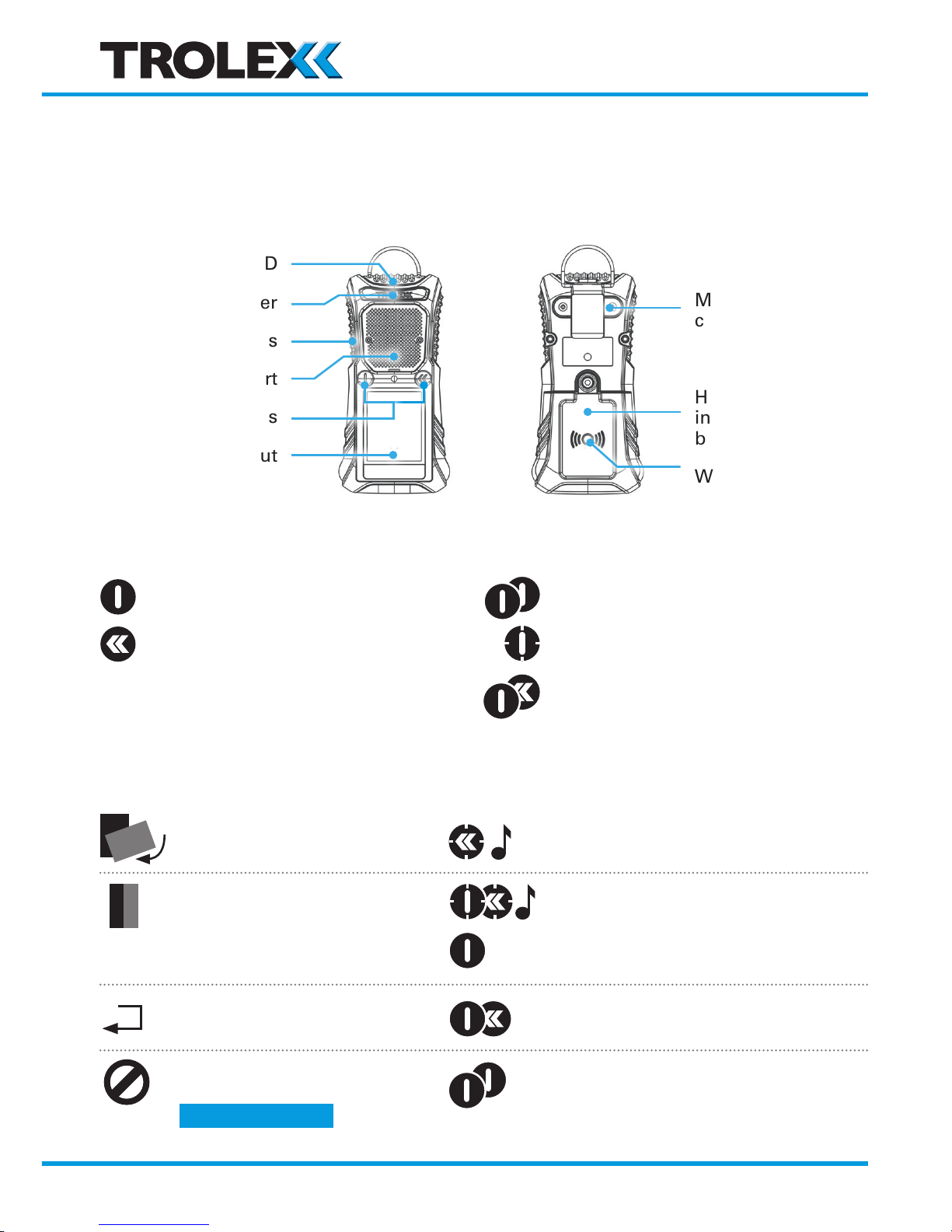
12 P5593.1600 Rev B
Invert display Click and hold
Adjust display contrast Click and hold both to access...
...then click to adjust
Return to MAIN DISPLAY Click both from any point in a MENU
Start/Stop pump Double click
4. Controls and Indicators
4.1 Layout
4.2 Main Function Buttons
4.3 Short-cut button functions
ON/OFF or select a function
Scroll menus
Double click
Click and hold
Click both together
Section 5.4 >>
Green On LED
Pump inlet cover
Red Alarm LEDs
Gas entry port
Push buttons
LCD readout
Mounting for
carrying clips
Hot swap
intrinsically safe
battery pack
Wireless
charging zone
www.trolex.com
Page 13
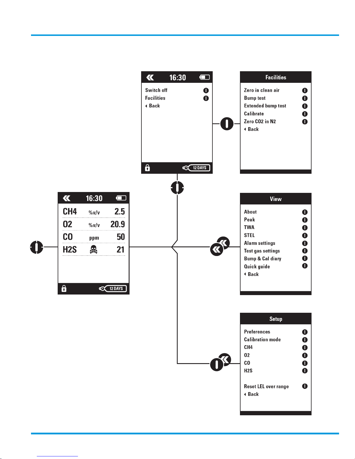
GasHawk TX7000 User Manual
P5593.1600 Rev B 13
5. Operation
5.1 Menu map
MAIN DISPLAY
Section 5.3
Section 6
Section 7
Section 8
www.trolex.com
Page 14
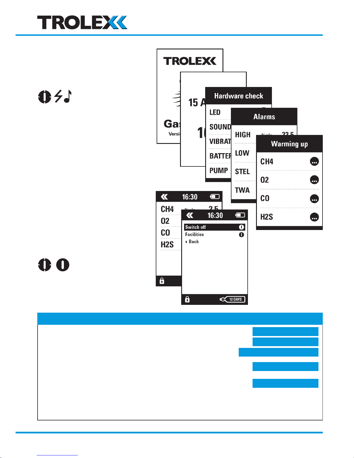
14 P5593.1600 Rev B
5.2 Switch On/Off
Switch ON
• Hardware condition check list
• Alarm settings for each sensor
• Sensor warming up
• Main display
Switch OFF
Checkpoint
• The switch ON sequence may be interrupted by FAULT messages.
• If BUMP TEST or CALIBRATE have been MANDATED any
further operation of the instrument will be suspended and the
FACILITIES screen displayed for resolution.
• Auto zero in clean air may occur in the sequence, where it has been
previously set up
• The CONDITION CHECK sequence will not
function if the battery pack is less than 25%
Section 5.3.2 >>
Section 8.2.1 >>
Section 8.1.12 >>
Section 9.1.13 >>
Section 8.2.2 & 6 >>
www.trolex.com
Page 15
GasHawk TX7000 User Manual
P5593.1600 Rev B 15
Checkpoint
System alerts
System alerts may occur at this point if a fault is present and will prevent any further operation.
Display illumination
The display illumination will automatically switch down to low level standby after a short period. It can
also be setup to switch completely OFF dependant upon which power saving mode is selected.
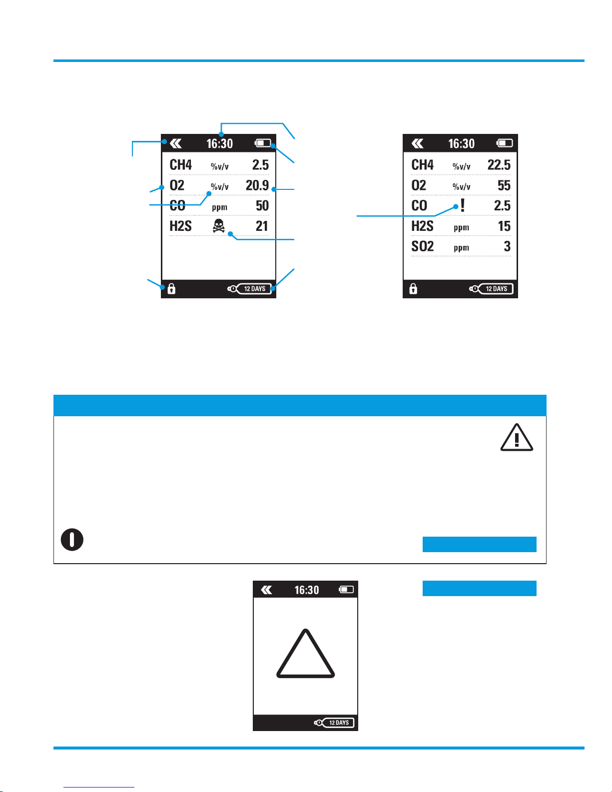
5.3 Main display
Function heartbeat
Type of gas
Units of gas
Continuous mode
Clock
Battery power
Gas concentration
Low alarm
High alarm
Days remaining
to calibration
Four Gas Format
LED fault
Alternative overview format
Five Gas Format
Section 8.1.16 >>
Section 8.1.2 >>
Click to restore display
SAFE
www.trolex.com
Page 16
16 P5593.1600 Rev B
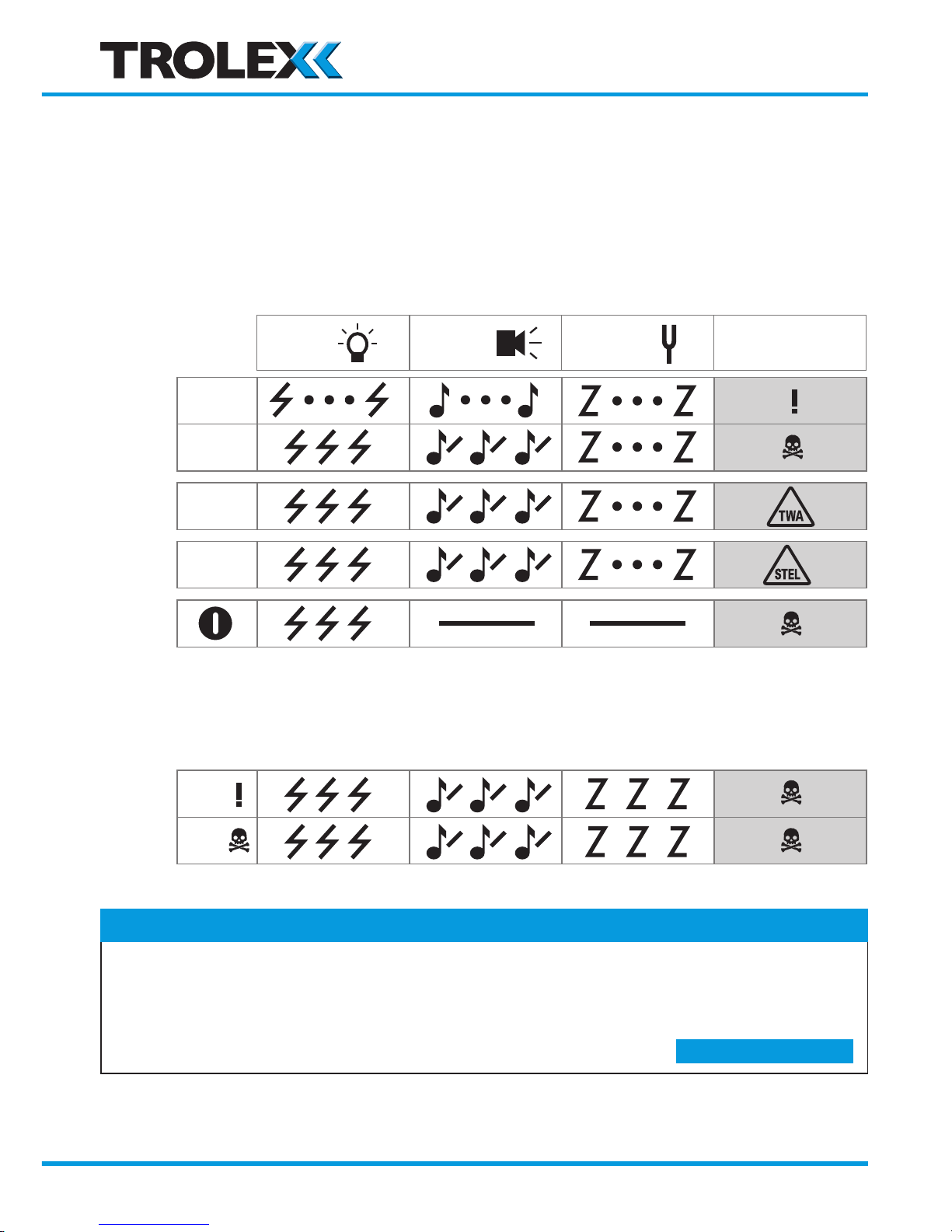
5.3.1 Alarms and messages
Gas alarms
Each gas sensor fitted has two independently adjustable alarm warning levels.
Some toxic gas sensors also have an independently adjustable TWA alarm warning level, plus
an independently adjustable STEL alarm warning alarm warning level.
Oxygen sensors have two independently adjustable CRITICAL alarms:
one for HIGH (Excess)
one for LOW (Depletion)
LED Audible Vibrator
Display
(Typical)
Low
High
Low
High
High
High
GAS
OXYGEN
TWA
STEL
MUTE
CO 10
CO 20
CO 20
O2 19
O2 23
CO
30
CO
200
Checkpoint
• LOW alarms can be set up to AUTO RESET or to LATCH
• HIGH alarms will always LATCH
• Audible alarms can be MUTED
• LATCHED alarms can be RESET when the gas concentration has receded
Section 8.1.6 >>
www.trolex.com
Page 17
GasHawk TX7000 User Manual
P5593.1600 Rev B 17
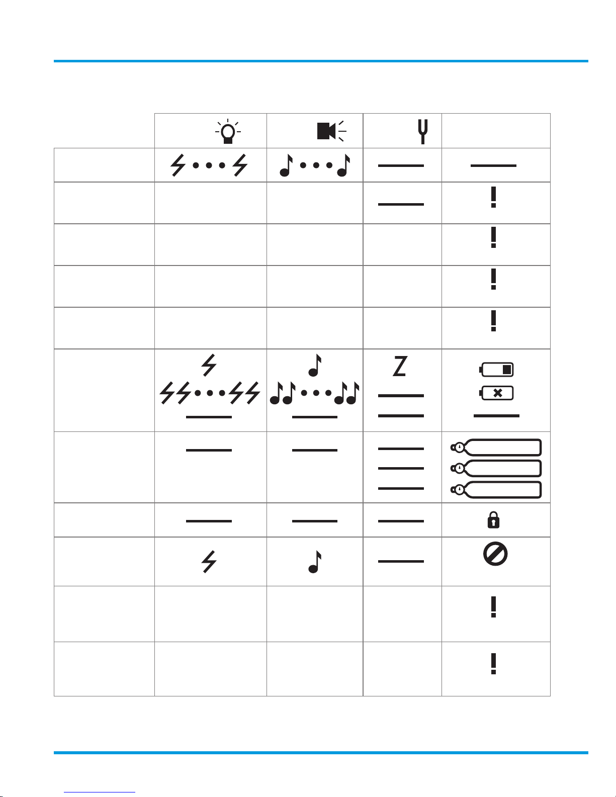
5.3.2 System and diagnostic alerts
LED Audible Vibrator Display
Condence alert
Sensor fault
Sensor fault
LED fault
LED fault
Audible fault
Audible fault
Vibrator fault
Vibrator fault
Battery low
Battery min
Shut down
Days to calibration
1 day to calibration
Overdue
Continuous ON
mode
Pump blocked
Pump blocked
Calibration is
overdue and is
mandated
Calibration required
Bump test is
overdue and is
mandated
Bump test required
12 days
1 day
0 days
www.trolex.com
Page 18
18 P5593.1600 Rev B
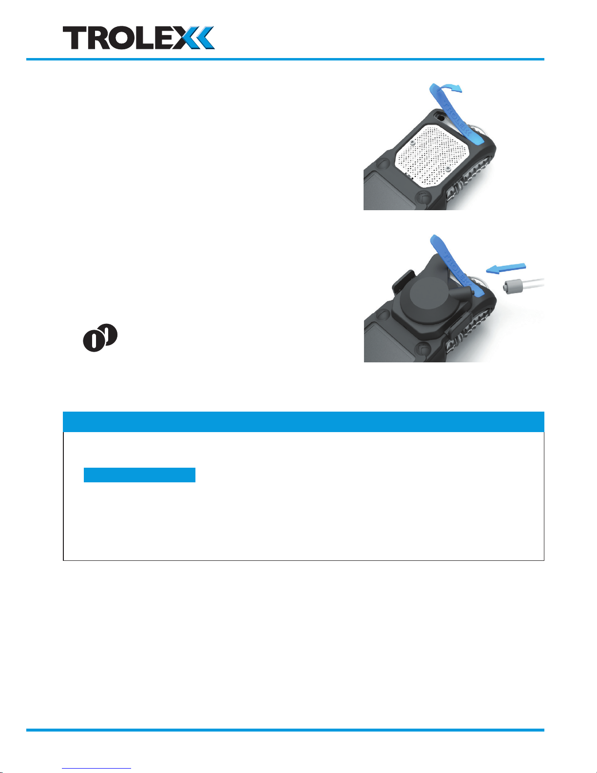
5.4 Pump operation
Some versions of the GasHawk are fitted with an
integral pump for assisted gas infusion in confined
space entry applications.
TX7000.xx.xx.xx.xx.xx.01
1. Lift the pump inlet cover
2. Clip the pump hood over the gas entry grill
ensuring that the gas entry inlet is fully engaged
3. Connect the suction tube
4. Double click to Start/Stop the pump
Checkpoint
• A pump alarm will be generated if the suction tube is blocked, or the filter in the pump hood is
blocked.
• The increased power requirement of the pump will reduce the normal battery run-time dependant on
frequency of use.
• Gas concentration reading can be diluted in conditions where air may be drawn into the
intake pipe along with the subject gas.
Section 10.3 >>
www.trolex.com
Page 19
GasHawk TX7000 User Manual
P5593.1600 Rev B 19
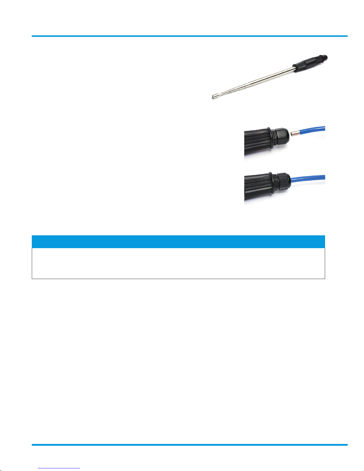
Telescopic Probe
Trolex accessory TX7012 Telescopic Probe can
be used to support the flexible suction tube to
aid access into restricted locations and confined
space applications:
• Extend the Telescopic Probe to the required length
• Push the suction tube through the clamping ring into the
Telescopic Probe and feed-in up to a positive stop.
• Hand tighten the clamping ring to hold the tube in position
Line Filter
A disposable Hydrophobic line filter should be fitted to the end of the flexible
suction tube or the Telescopic Probe to prevent water or particle ingress.
Checkpoint
• When extending or collapsing the Telescopic Probe, move each section one-at-a-time, to the desired
length. Rapid end-to-end pulling and pushing may stress and damage the sliding couplings.
• Apply light lubricating oil to the Probe when required to ensure smooth operation.
www.trolex.com
Page 20
20 P5593.1600 Rev B
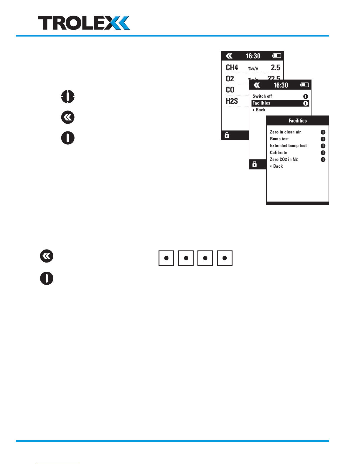
6. Facilities
Selection and control of the ancillary functions
when required
6.1 Enter a password
A password may be requested for Facilities menu if security is active. Factory default 1959.
Enter a digit
Confirm and step
www.trolex.com
Page 21
GasHawk TX7000 User Manual
P5593.1600 Rev B 21
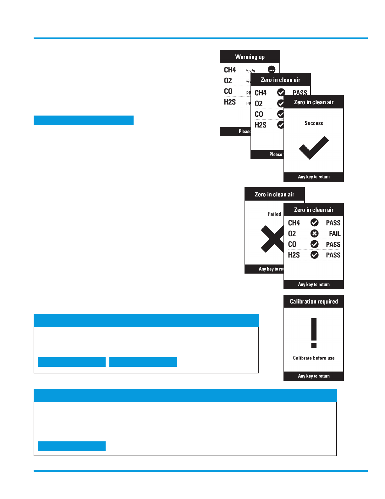
6.2 Zero in clean air
All gas sensors will be simultaneously reset to
Zero assuming clean air.
Zero in clean air can also be setup to occur
automatically during the switch ON routine
• Progressive display of each sensor status
• The SUCCESS event is logged in the main
log register
Individual sensor result listing, alternates with a FAILED alert
The FAILED alert is logged in the main log register
CALIBRATE THE INSTRUMENT AS SOON AS POSSIBLE
Checkpoint
• Ensure that the local atmosphere is clean and free of subject gases
• Zero in clean air will set a CO2 sensor to 0.4% CO
2
• Options are available to set the oxygen ‘zero’ at either 20.8% v/v or 20.9% v/v
Checkpoint
• If CALIBRATE has been MANDATED in the setup menu, it will not be
possible to use the instrument on the next occasion that it is switched
ON, until calibration has been performed.
Section 5.2 and 8.1.13 >>
Section 8.2.2 >> Section 8.2.3 >>
Section 8.4 >>
www.trolex.com
Page 22
22 P5593.1600 Rev B
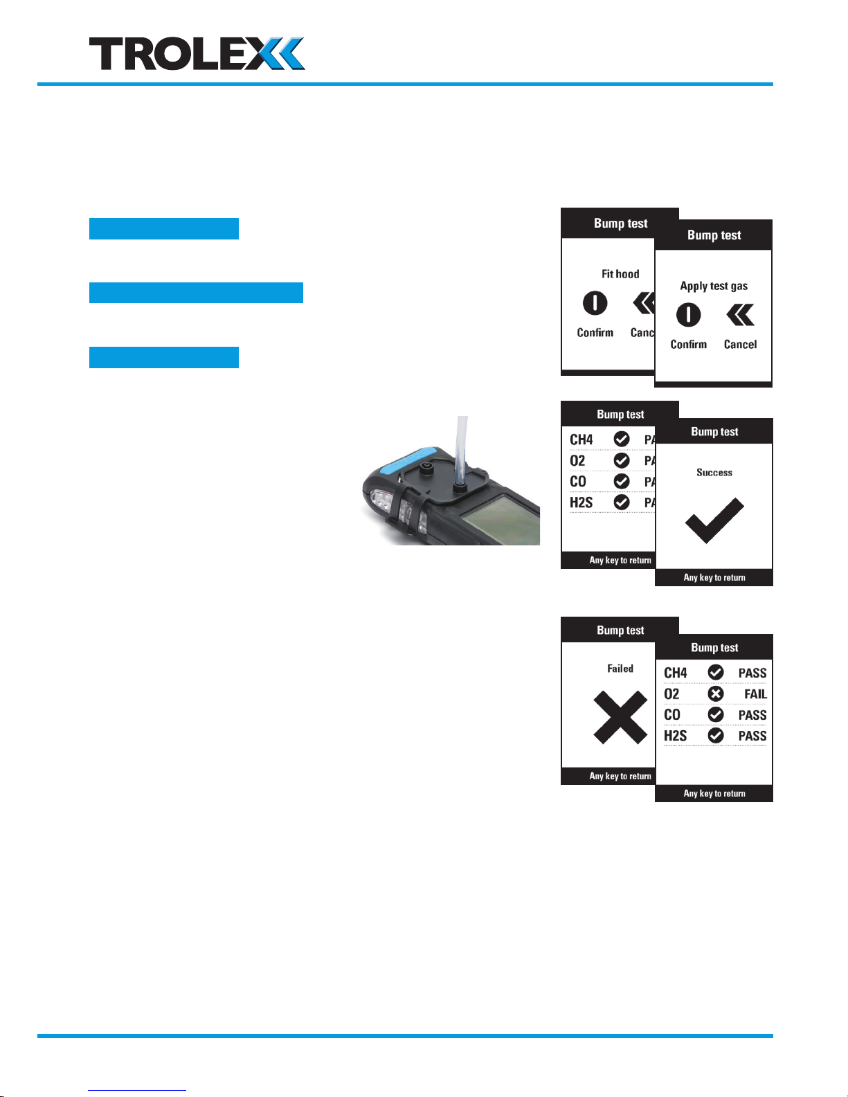
6.3 Bump Test
Apply a test gas for each type of sensor installed to check the overall functional response.
The test gas concentration values must be initially set up and must concur with the values
marked on the gas canister.
The Bump Test event can be OPTIONAL or MANDATED
The BUMP TEST DUE interval can be setup
Connect on of the gas ports
of the Test Gas Hood to the
Test Gas Canister
Switch on gas supply
Each gas sensor attains 30%
full scale value within 30 seconds
The SUCCESS event is logged in the Bump and Calibration
diary, and in the Main Log Register
Individual sensor results log alternates with a
FAIL alert
The FAILED event is logged in the bump and
Calibration diary, and in the main Log Register
CALIBRATE THE INSTRUMENT AS SOON AS POSSIBLE
Section 8.2.4 >>
Section 8.2.6 >>
Section 8.2.1 and 7.7 >>
www.trolex.com
Page 23
GasHawk TX7000 User Manual
P5593.1600 Rev B 23
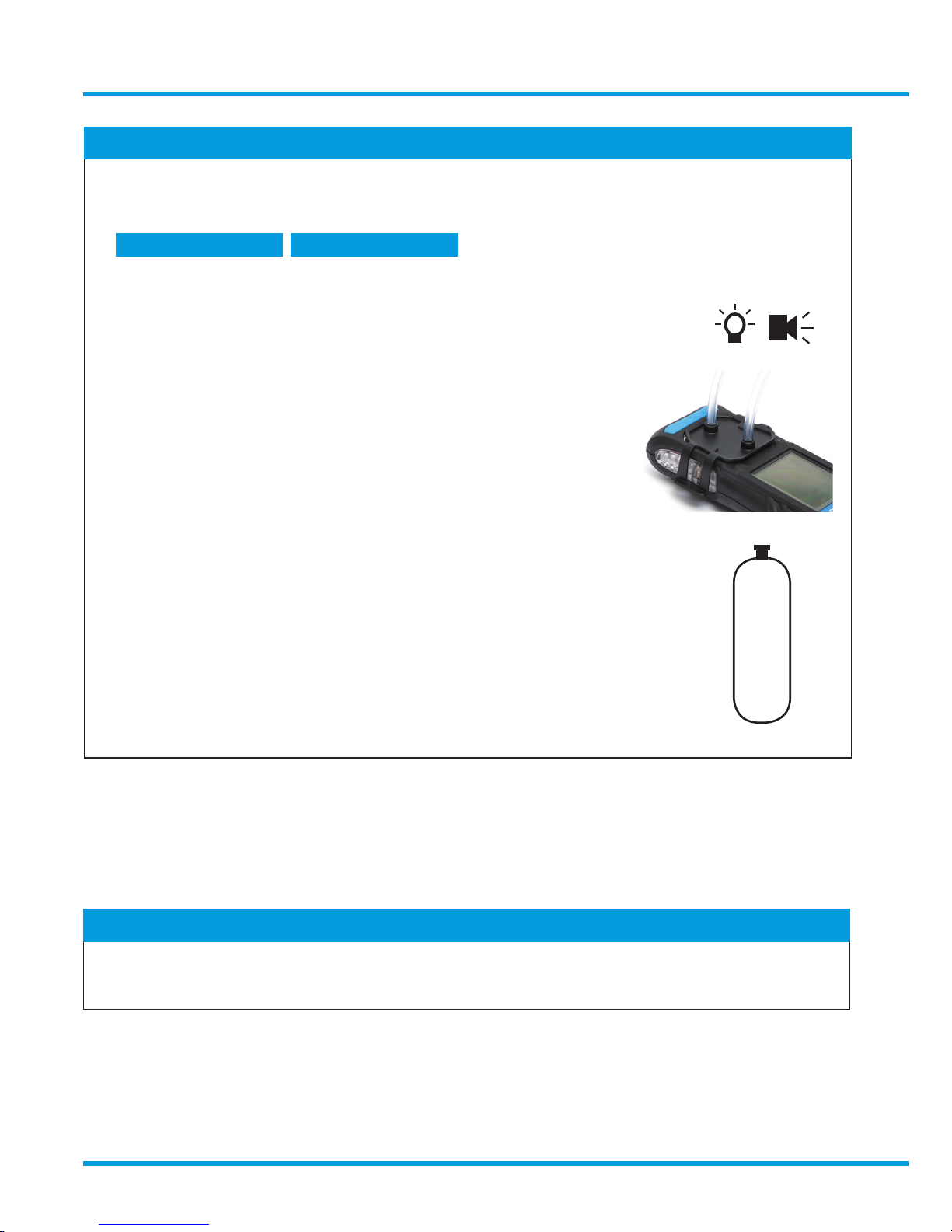
6.4 Extended bump test
An extended bump test is the same procedure as a standard bump test.
Sensor response qualification: Attain 90% FS within 60 seconds.
Checkpoint
• If CALIBRATE has begun MANDATED in the setup menu, it will not
be possible to use the instrument on the next occasion that it is switched
ON, until calibration has been done
• All ACTIVE sensors must qualify for a successful bump test
• Audible and visual alarms will be generated during the bump test where alarm
set-points are exceeded.
• A second gas port is available on the test gas hood for exhausting
the gas to a ventilated area if required.
• The bump test procedure described assumes a single gas canister - one for each
gas sensor. Mixed gas sources may also be used, calibrated for the range of
sensors installed.
Checkpoint
• A longer bump test is inherently more accurate, as response is extended over a wider scale range.
• Test time will be increased, so more test gas will be consumed.
Section 8.2.2 >> Section 8.2.3 >>
CH
4
+
O2
+
CO
+
H2S
www.trolex.com
Page 24
24 P5593.1600 Rev B
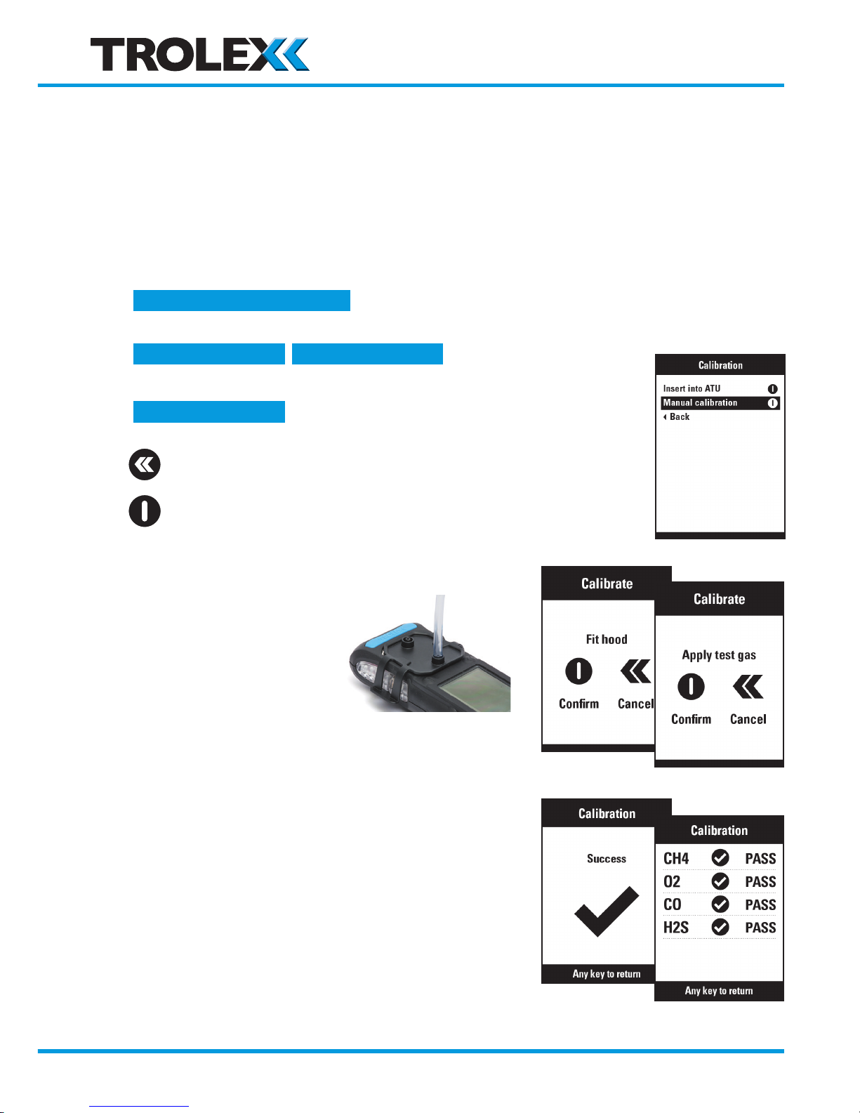
6.5 Calibrate
There are two methods of calibration using calibrated test gas:
1. Use a Trolex TX7005 Universal Docking Station
2. Manual calibration using the standard test gas hood supplied with the instrument.
• The test gas concentration values must be initially set up and must concur with the
values marked on the gas canister.
• The CALIBRATION event can be OPTIONAL or
MANDATED.
• The CALIBRATION DUE interval can be setup.
Scroll to MANUAL CALIBRATION
Select
• Connect one of the
gas ports of the Test
Gas Hood to the Test
Gas Canister
• Switch on gas supply
• Each gas sensor is calibrated within a fixed
time limit
• The SUCCESS event is logged in the Bump and
calibration diary and the main Log Register.
Section 8.2.2 >> Section 8.2.3 >>
Section 8.2.5 >>
Section 8.2.1 and 7.6 >>
www.trolex.com
Page 25
GasHawk TX7000 User Manual
P5593.1600 Rev B 25
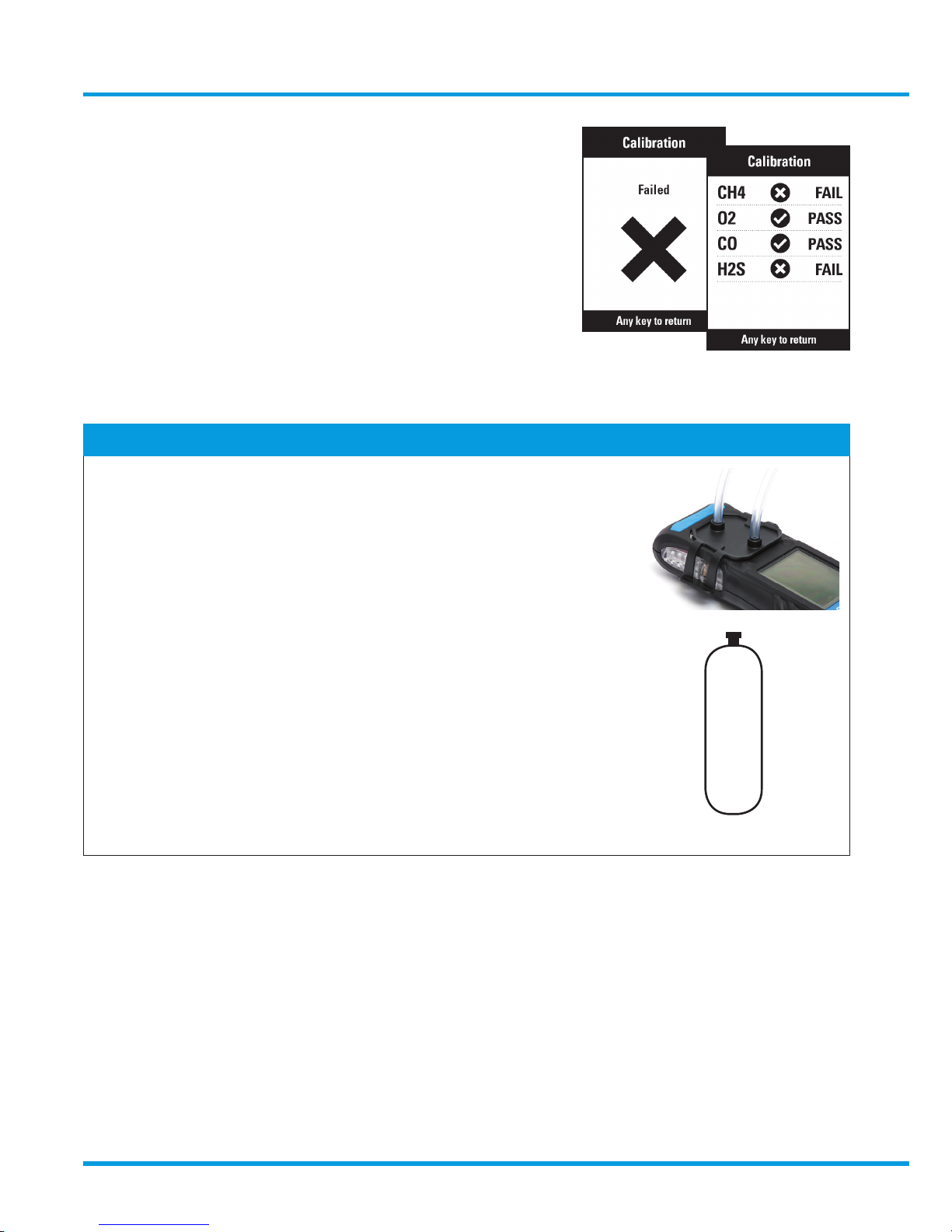
• Individual sensor results listing alternates with a
FAIL alert
• The FAILED event is logged in the Bump and
Calibration Diary, and in the Main Log Register
• SERVICE THE INSTRUMENT AS SOON AS POSSIBLE
Checkpoint
• A second gas port is available on the test gas hood for exhausting
the gas to a ventilated area if required.
• The calibration procedure described assumes a single gas canister
- one for each gas sensor. Mixed gas sources may also be used calibrated
for the range of sensors installed.
CH
4
+
O2
+
CO
+
H2S
www.trolex.com
Page 26
26 P5593.1600 Rev B
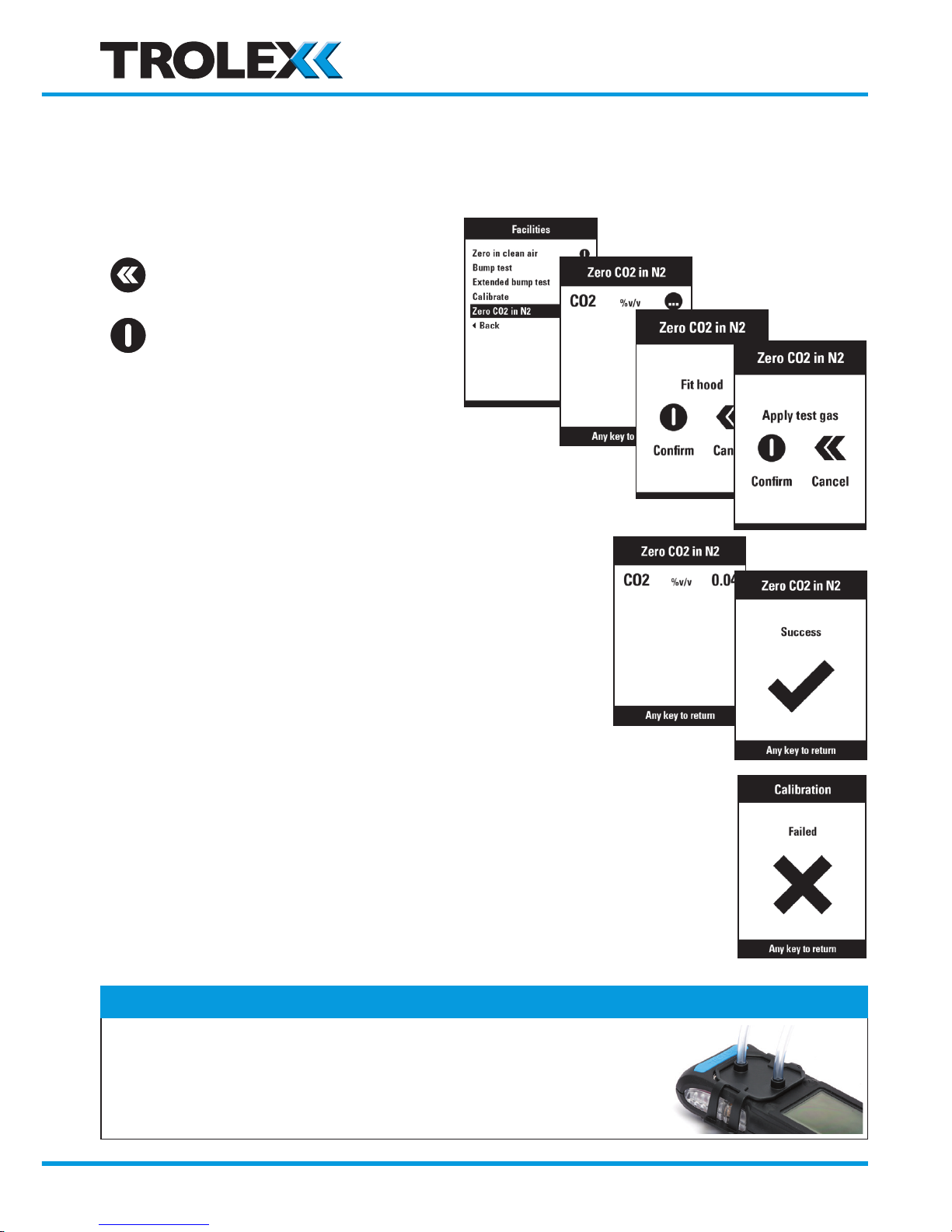
6.6 Zero CO2 in N2
When a CO2 sensor is fitted it should be reset to zero using Nitrogen gas in place of the
normal fresh air method.
Scroll to Zero CO2 in N2
Select
• Warm up
• Connect one of the gas ports of the Test Gas
Hood to the Test Gas Canister
• Switch ON gas supply
• The gas sensor will zero within a fixed time period
• The SUCCESS event is logged in the Bump and
Calibration diary and the main Log Register
• Individual sensor results listing, alternates with a FAIL alert
• The FAILED event is logged in the Bump and Calibration Diary, and in
the Main Log Register
• SERVICE THE INSTRUMENT AS SOON AS POSSIBLE
Checkpoint
• A second gas port is available on the test gas hood for exhausting
the gas to a ventilated area if required.
www.trolex.com
Page 27
GasHawk TX7000 User Manual
P5593.1600 Rev B 27
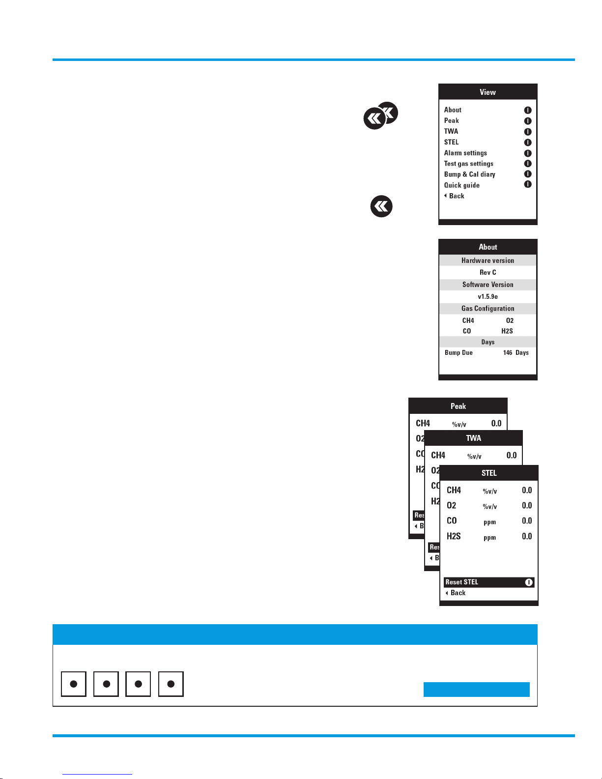
7. View
• Double click to view menu
• System information, setup data and current
stored data can be viewed.
• Displayed data cannot be changed
• Auto step BACK after a short period
7.1 ABOUT
• View system data and software versions
7.2 PEAK
• View peak sensor values attained since last reset
• Reset PEAK values to Zero
7.3 TWA
• View the TIME WEIGHTED AVERAGE accumulated values
• Reset TWA accumulated values to Zero
7.4 STEL
• View SHORT TERM EXPOSURE LIMIT accumulated values
• Reset STEL accumulated values to Zero
Checkpoint
A PASSWORD may be required for the reset PEAK, reset TWA and reset STEL functions if security is active
Factory default: 1959
Section 8.1.8 >>
www.trolex.com
Page 28
28 P5593.1600 Rev B
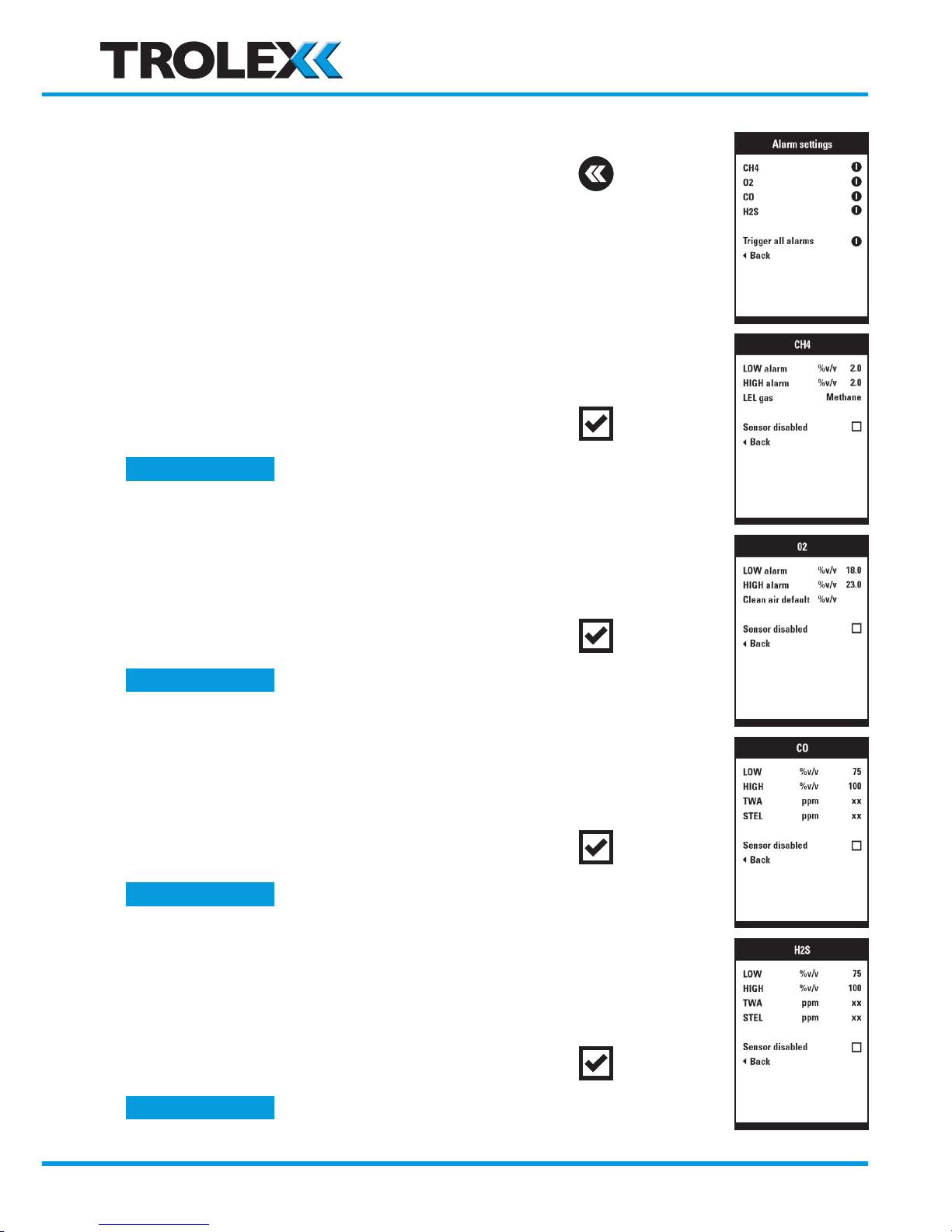
7.5 Alarm Settings
• Select which sensor is to be viewed
• Momentarily trigger all alarm set points to test
response of the alarm systems
CH4 and LEL alarms
• View the preset alarm levels
• View the alternative flammable gas substitute
• The sensor has been DISABLED and is not active
O2 Alarms
• View the preset alarm levels
• View selected clean air default value
• The sensor has been DISABLED and is not active
CO Alarms
• View the present alarm levels
• View the TWA and STEL alarm levels
• The sensor has been DISABLED and is not active
H2S Alarm levels
• View the preset alarm levels
• View the TWA and STEL alarm levels
• The sensor has been DISABLED and is not active
Section 8.4 >>
Section 8.5 >>
Section 8.6 >>
Section 8.3 >>
www.trolex.com
Page 29
GasHawk TX7000 User Manual
P5593.1600 Rev B 29
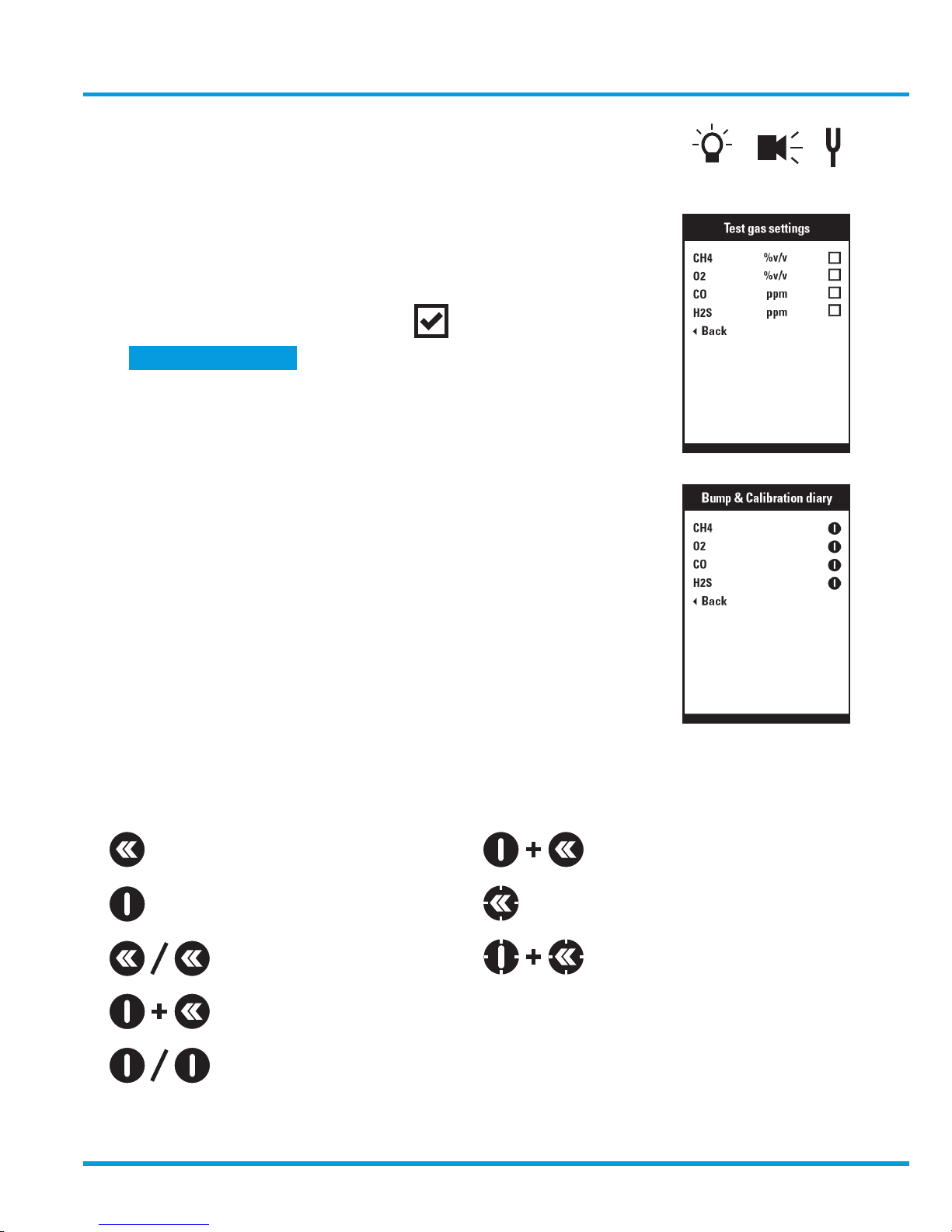
7.6 Test Gas Values
• View the preset expected test gas values to be applied
to each gas sensor
• A test gas has been INCLUDED
7.7 Bump and Calibration diary
View information about:
• Bump Test and Calibration status
• Last Bump Test date
• Days remaining to next Bump Test
• Last Calibration date
• Calibration Due Days remaining
7.8 Quick guide
• Brief overview of push button operations
Trigger all alarms
Scroll down
Select
View
Setup
Pump stop-start
Back from a menu
Hold: Invert display
Hold: Access contrast
Section 8.2.4 >>
www.trolex.com
Page 30
30 P5593.1600 Rev B
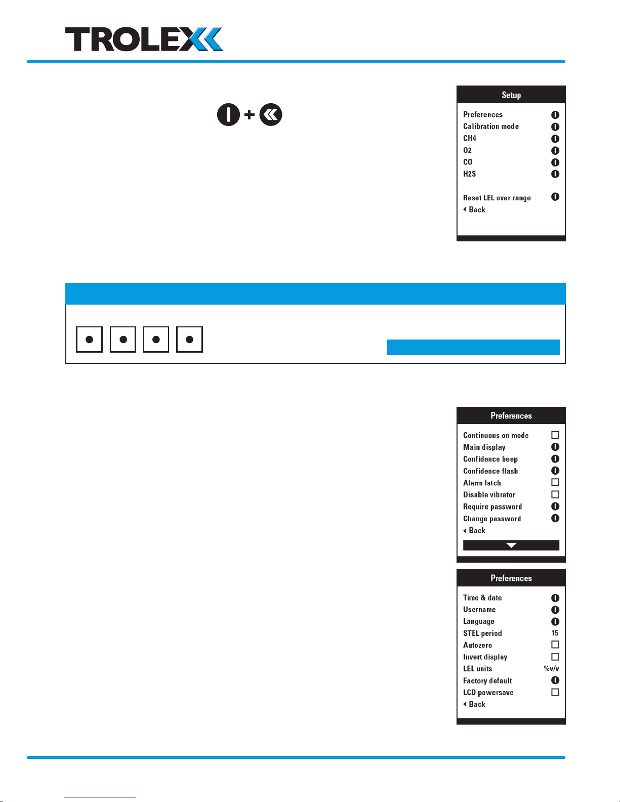
8. Setup
Click both for setup menu
• Setup the functional parameters of GasHawk
• Setup the calibration parameters
• Setup each sensor alarm function
• Reset a LEL catalytic sensor that has previously ‘Latched’
after an over-range condition
8.1 Preferences
Select which functions are to be setup to user preference
Checkpoint
• A password will be requested for access to the SETUP menu if security is enabled
Factory default: 1959
Section 8.1.8 and 8.1.9 >>
www.trolex.com
Page 31
GasHawk TX7000 User Manual
P5593.1600 Rev B 31
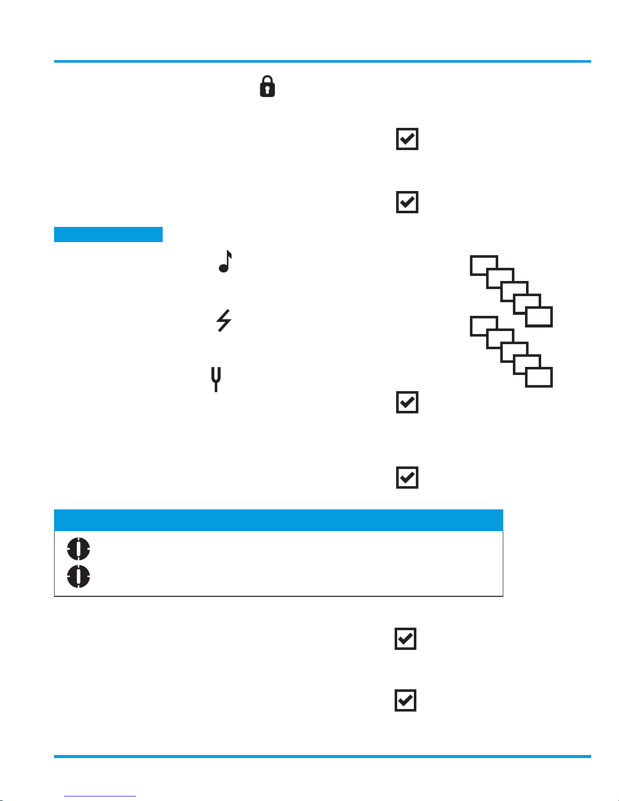
8.1.1 Continuous ON mode
It will not be possible to switch OFF GasHawk
A Require Password will be automatically activated to prevent
access to SETUP functions
8.1.2 Main display
Change the normal main display format to an overview SAFE icon
8.1.3 Confidence beep
Set the interval of the confidence beep
8.1.4 Confidence flash
Set the interval of the confidence flash
8.1.5 Disable vibrator
Switch the vibrator OFF for power saving
8.1.6 Alarm latch
Set LOW alarm signals to LATCH until reset
(a HIGH alarm signal will always LATCH until reset)
8.1.7 Invert display
180o display rotation for inverted viewing
8.1.8 Require password
A password will be requested where security is applied
Section 5.3 >>
OFF
15s
30s
45s
60s
OFF
15s
30s
45s
60s
Checkpoint
Click and hold to MUTE an audible alarm
Click and hold to RESET a LATCHED alarm when the gas concentration has receded.
www.trolex.com
Page 32
32 P5593.1600 Rev B
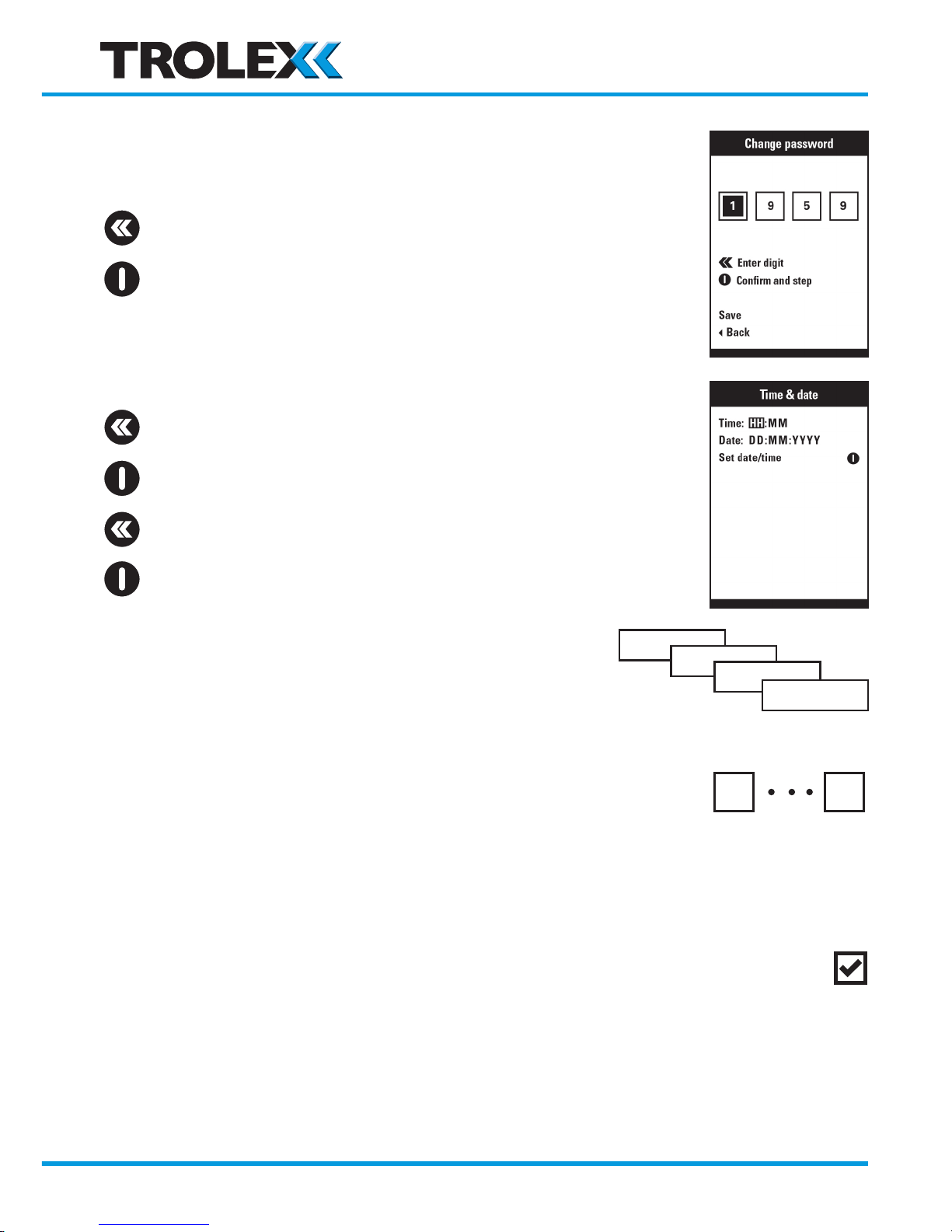
8.1.9 Change password
Enter a four digit password
Enter digits
Confirm and step
8.1.10 Time & Date
Set the time and date
Step through each field
Select a field
Increment the characters
Set Date/Time
8.1.11 Language
Select the display language
8.1.12 STEL Period
Set the STEL sampling period
Selectable: 5 to 15 minutes
8.1.13 Auto zero start up
• Auto zero of all sensors will be done during the start up period
when GasHawk is switched ON
• An additional auto zero progress display will appear in the start up routine
Factory default
5
15
English
Russian
Chinese
Other
www.trolex.com
Page 33
GasHawk TX7000 User Manual
P5593.1600 Rev B 33
8.1.14 LEL Units
Select the units of LEL for flammable gas sensors
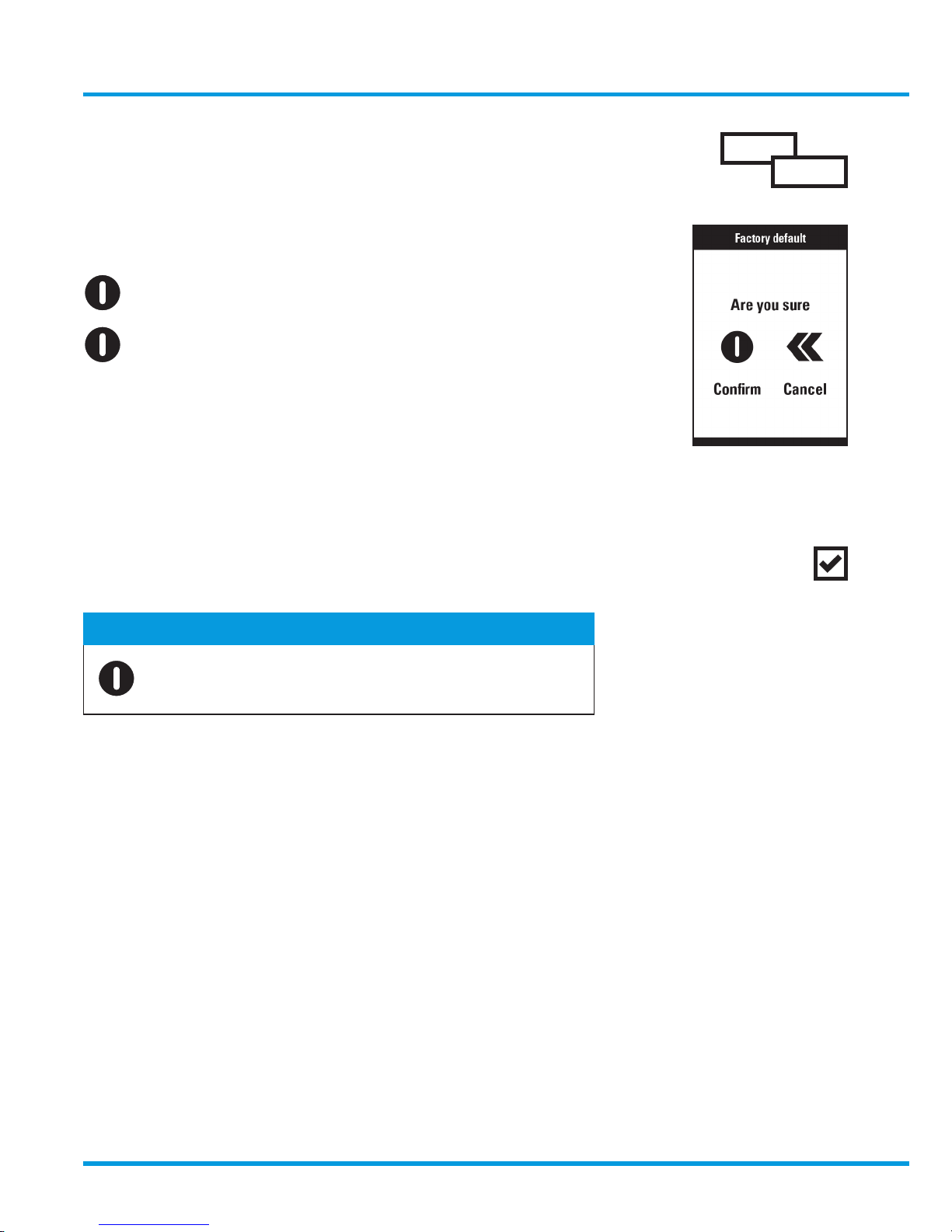
8.1.15 Factory default
Request factory reset default
Click to confirm
8.1.16 LCD power save
The LCD display will automatically switch OFF completely
after a short period to save battery power
Checkpoint
Click to restore the display illumination
%v/v
%LEL
www.trolex.com
Page 34

34 P5593.1600 Rev B
8.2 Calibration mode
Setup the required calibration and bump test operating parameters
8.2.1 Mandate bump
GasHawk operation will be suspended when next switched on until
a bump test is done, if the bump test interval has expired
8.2.2 Mandate calibration if fail
GasHawk operation will be suspended when next switched on, until
a calibration is done, if a gas sensor is out of range
8.2.3 Mandate calibration when due
GasHawk operation will be inhibited, when next switched ON, until
a calibration is performed, if the calibration interval has expired
8.2.4 Test gas values
Set up the values of each test gas concentration that will be applied to
the sensors for bump test and calibration purposes
A test gas can be excluded where a mixed test gas canister is being
used, where one or more of the required test gases are absent
Checkpoint
Click both to delete last digit
The available gas value adjustment range is limited to safe minimum and maximum limits appropriate to
each gas type. Invalid gas value settings will not be entered.
2.3
1.3
1.3
2.3
2.30
Scroll to the gas value to be setup e.g.
Highlight the gas value
Increment a digit
Traverse the digits
www.trolex.com
Page 35
GasHawk TX7000 User Manual
P5593.1600 Rev B 35
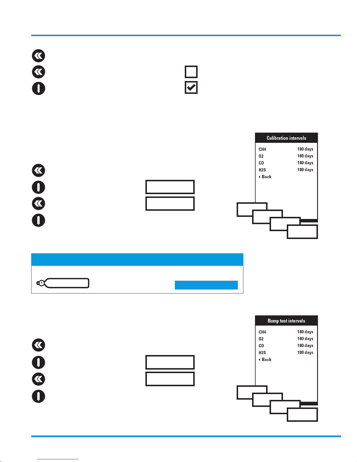
8.2.5 Calibration intervals
Set up the calibration time intervals to be applied to each gas sensor
Scroll to the sensor to be set up
Highlight the time interval
Increment the interval
Exit highlight
Repeat setup for each sensor
8.2.6 Bump test intervals
Setup the bump test time intervals to be applied to each gas sensor.
Scroll to the sensor to be set up
Highlight the time interval
Increment the interval
Exit highlight
Repeat setup for each sensor
Checkpoint
Days remaining to calibration also displayed on the MAIN DISPLAY
Section 5.3 >>
12 days
7 days
30 days
60 days
180 days
Exit highlight
Scroll to gas status
Click to INCLUDE a gas
Repeat setup for each gas
7 days
30 days
60 days
180 days
180 days
180 days
7 days
7 days
www.trolex.com
Page 36
36 P5593.1600 Rev B
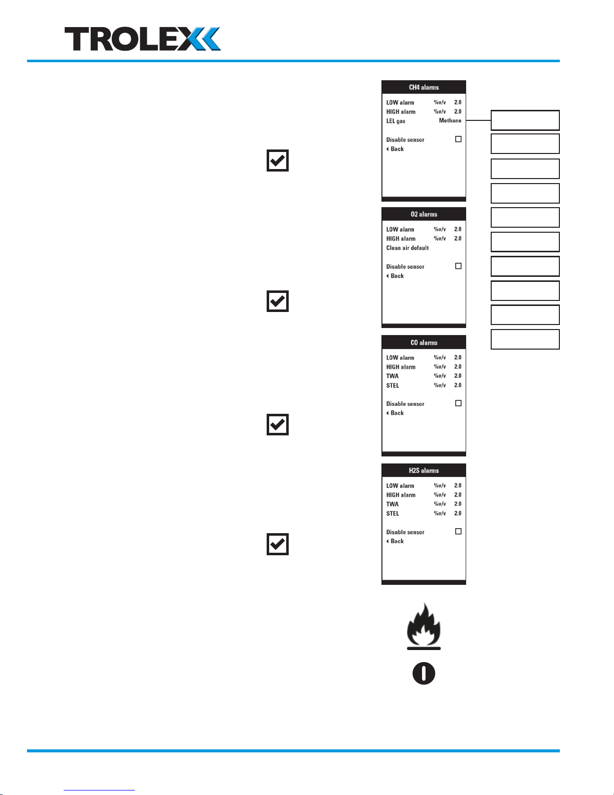
8.3 CH4 LEL alarms
Set the low alarm level
Set the high alarm level
Select an alternative flammable gas
Disable the sensor when not active
8.4 O2 alarms
Set the low alarm level
Set the high alarm level
Select clean air default value
Disable the sensor when not active
8.5 CO alarms
Set the low alarm level
Set the high alarm level
Disable the sensor when not active
8.6 H2S alarms
Set the low alarm level
Set the high alarm level
Disable the sensor
8.7 Reset LEL alarms
A catalytic flammable gas sensor will LATCH in the
HIGH condition when the LEL point is exceeded.
Reset when the gas has receded
Methane
Propane
Butane
Ethylene
Propene
Acetylene
Cyclopropane
Cyclohexane
Benzene
Toluene
www.trolex.com
Page 37
GasHawk TX7000 User Manual
P5593.1600 Rev B 37
10. Maintenance
10.1 Service and Calibration
GasHawk should be calibrated in compliance with appropriate statutory requirements, or at
least every 6 months, to ensure accurate response. A prompt will appear on the display.
Recalibrate the instrument if necessary.
Contact our Product Support Department, or your local distributor, for a choice of service and
calibration options to suit individual requirements
10.2 Annual Safety Check
The instrument is crucial to personal safety and it is recommended that it be returned to our
Product Support Department, or to your local distributor, for an annual safety check.
Itemised details of this safety check can be supplied on request.
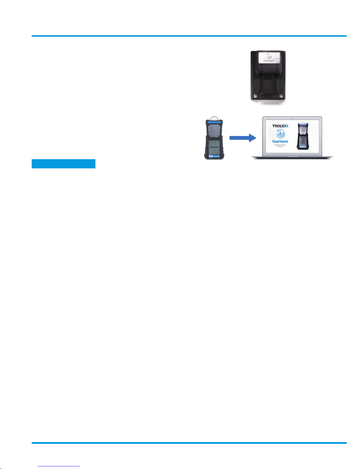
9. Data Logging and Data
Communications
The TX7005 Universal Docking Station provides
bump test, calibration and battery charging all in one
convenient table-top package. The Trolex HawkEye
PC application and USB data exchange also enables
the GasHawk data-log to be downloaded with PC
setup and cloning of GasHawk operating functions.
An SD card slot is also available for data to be stored
as an independent record.
Section 12 >>
www.trolex.com
Page 38

38 P5593.1600 Rev B
11. Precautions
11.1 Operating Safety
The instrument must be operated in accordance with the operating data to maintain safety,
reliability, and to preserve the intrinsic safety integrity.
Gas monitoring procedures should always be carried out in accordance with the regulations
of Safety Authorities and in compliance with any local mandatory safety regulations.
11.2 Hazardous Areas
Do NOT dismantle the instrument whilst in a hazardous area
11.3 Evacuation
If the instrument alarm initiates due to dangerous levels of gas concentration, leave the area
immediately and implement statutory safety procedures.
11.4 Battery Charging
Recharging of the battery must only be carried out using the Trolex charger supplied with the
instrument. Do not charge the battery in a hazardous area.
11.5 Flammable gas sensors
It is good safety practice to perform a sensitivity test of the instrument before each day’s use
with a known concentration of methane between 25% and 50% LEL (1.25% and 2.5% v/v).
Accuracy must be within 10% of actually reading (section 6.3).
If not, the instrument should be recalibrated.
Catalytic combustion gas sensors positively react to the presence of oxygen in the
atmosphere ad should only be used for gas concentration up to the Lower Explosive Limit
(LEL).
After this point, the output of the sensor becomes non-linear and may erroneously indicate
that the gas concentration is below the explosive limit.
They should not be used in oxygen enriched atmospheres and conversely, severe oxygen
deficiency. This will affect the sensitivity of the sensor.
www.trolex.com
Page 39

GasHawk TX7000 User Manual
P5593.1600 Rev B 39
Catalytic combustion gas sensors can detect a wide range of flammable gases but they
cannot discriminate between individual gases. They will respond to most, or all, of the
flammable components present in the atmosphere without distinguishing between them.
If the atmosphere to be monitored contains gas that dilutes or displaces the air, this may
reduce the response of the catalytic sensor. Similarly, steam laden atmospheres and
condensation can reduce the sensitivity.
The response of the catalytic combustion sensors can be affected by airborne contaminants
which will reduce the sensitivity. Substances such as silicones, tetraethyl lead, sulphur
compounds and phosphate can cause permanent degradation and halogenated carbons may
cause temporary inhibition.
Exposure to high concentrations of flammable gas greater than the LEL can affect the
sensitivity of catalytic combustion sensors and the calibration should be checked after such
exposure.
Be aware that most flammable gases and vapours are also toxic at low percentages of LEL.
11.6 Toxic Gas Sensors
It is good safety practice to perform a sensitivity test of the instrument before each day’s use
with a known test concentration of the subject gas.
Recalibrate if necessary.
Electrochemical gas sensors contain an electrolyte that is gradually consumed during use.
The average life is about two years, dependant on the duty cycle. The response should be
checked at regular intervals.
Electrochemical gas sensors for toxic gases can be affected by other interfering gases which
may displace the subject gas being monitored. Steam laden atmospheres and condensation
can also reduce sensitivity.
Be aware that some toxic gases are also ‘flammable’ at high percentage concentrations.
11.7 Servicing and Repair
The instrument is certified intrinsically safe and must be serviced and repaired at Trolex,
or a service agent approved by Trolex, in order to preserve the intrinsically safe integrity.
Substitution of components and any additions or changes to the product will invalidate the
Product Warranty and may contravene the terms of intrinsically safe certificate.
www.trolex.com
Page 40

40 P5593.1600 Rev B
11.8 Disposal
Exhausted batteries and some gas sensor cells contain mildly corrosive substances and
must be disposed of in the correct manner. Make sure that the battery is completely
discharged before disposal.
For guidance regarding end-of-life disposal of a GasHawk unit, please contact the
Environmental Management Representative at Trolex Ltd.
11.9 Contamination
The instrument is sealed against the ingress of dust and water.
It will even tolerate temporary immersion in water but should be removed as quickly as
possible to avoid contamination of the gas sensing ports.
Ensure that the ports are completely dry and free of contamination before further use.
11.10 Aggressive Chemicals
The housing of the instrument is a combination of polycarbonate with a TPE overmould.
These materials are selected for durability and resistance to normal external contaminants.
Consider the integrity of the housing if it is exposed to aggressive chemicals which may be
encountered in the hazardous area.
11.11 Atmospheric Pressure Variations
The response of O2, CO2 and infrared CH4 sensors can be affected by changes in
atmospheric pressure so active pressure compensation is incorporated to maintain stability
over natural variations.
Abnormal rapid changes in pressure, such as passing through an air lock, may cause a
temporary shift in the O2 reading. Allow several seconds for the sensor to equalise and
ensure that oxygen levels are adequate during this period.
11.12 Condensation
The accuracy of infrared sensors can be temporarily reduced by the formation of
condensation.
The sensor will accommodate normal day-to-day variations but rapid changes of temperature
and humidity from a cold condition to a hot and humid environment should be avoided –
allow several minutes for the instrument temperature to equalise before use.
www.trolex.com
Page 41
GasHawk TX7000 User Manual
P5593.1600 Rev B 41
12. Accessories
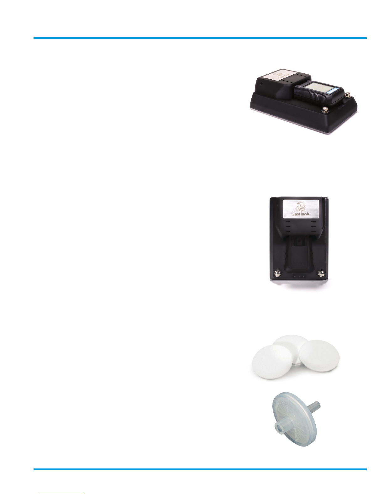
Bump Test Station
TX7004
• Input ports for test gas connections.
• Gas application push button for convenient and safe
operation.
• No electrical power required – can be used in any
location.
• Single or dual gas input channels.
Universal Docking Station
TX7005
• Combined bump test, Calibration and Charging with PC
datacomms in a convenient simple to use package
• Single or dual input ports for a test gas connections
• USB datacomms, data-log transfer using Trolex
HawkEye PC application tool.
• Instrument setup from PC and cloning function
• Gas application switches for convenient and safe operation.
• USB connecting lead
• Universal mains power supply 90–265V AC 50/60Hz 250mA
• Secure in-vehicle docking for rough terrain applications.
Pump hood filters
P5593.87 (pack of 5)
• Annular filters for fitting in to the pump hood
Line filters
P5593.88 (pack of 5)
• Hydrophobic line filter cassette to prevent moisture
ingress into the suction tube.
www.trolex.com
Page 42
42 P5593.1600 Rev B
13. Certification and conformity
13.1 European Union and International Certification
13.1.1 Underground mines
13.1.2 Surface industry with explosive gas atmospheres
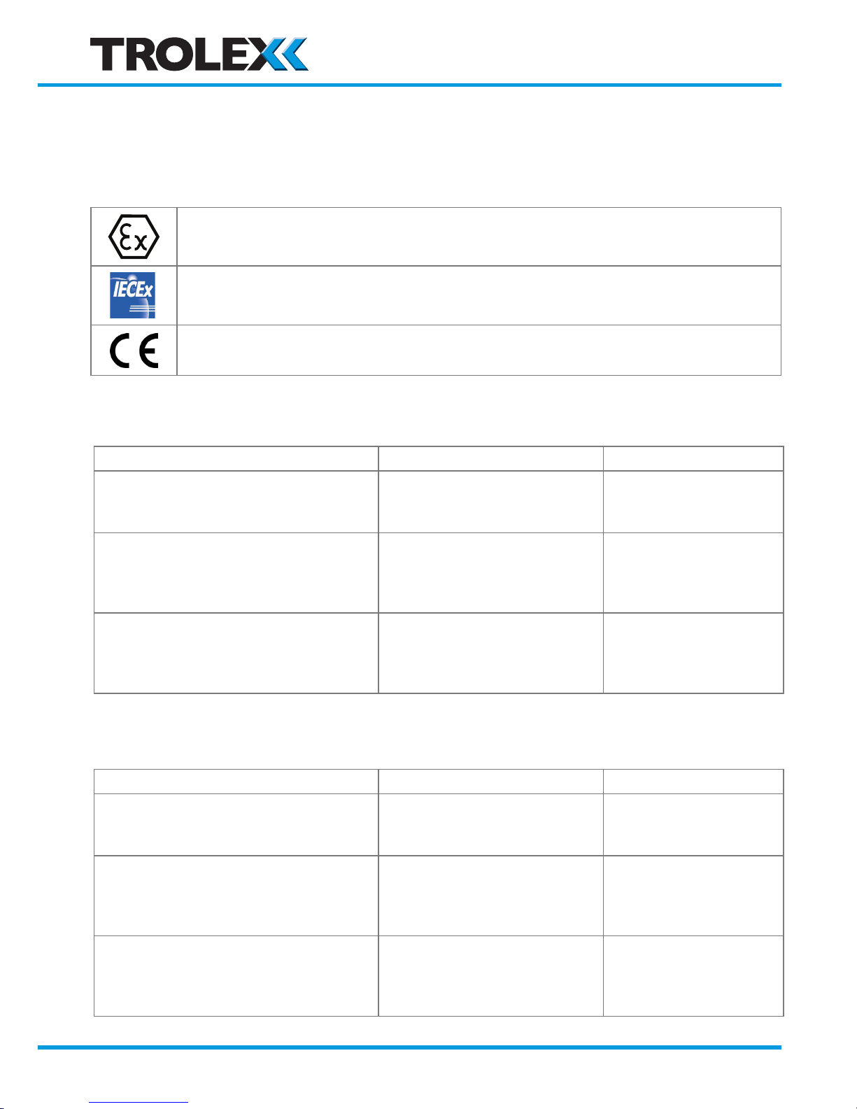
ATEX (European Union) certification for use in underground mines and surface industry
with explosive gas atmospheres.
IECEx (International) certification for use in underground mines and surface industry with
explosive gas atmospheres.
Complies with ATEX Directive 2014/34/EU
Complies with EMC Directive 2014/30/EU
Product Code: Ex Certificate Number: Ex Certification Code:
TX7000.19.xx.xx.xx.xx.xx.xx.xx
CML 15ATEX2122X
IECEx CML 15.0062X
I M1
Ex ia I Ma
-20 °C ≤ Ta ≤ +50 °C
TX7000.19.xx.xx.xx.07.xx.xx.xx
TX7000.19.xx.xx.xx.08.xx.xx.xx
TX7000.19.xx.xx.xx.09.xx.xx.xx
(when used with Ex d Sensor)
CML 15ATEX2122X
IECEx CML 15.0062X
I M1
Ex ia d I Ma
-20 °C ≤ Ta ≤ +50 °C
TX7000.19.xx.xx.xx.01.xx.xx.xx
TX7000.19.xx.xx.xx.02.xx.xx.xx
TX7000.19.xx.xx.xx.03.xx.xx.xx
(when used with Ex da Sensor)
CML 15ATEX2122X
IECEx CML 15.0062X
I M1
Ex ia da I Ma
-20 °C ≤ Ta ≤ +50 °C
Product Code: Ex Certificate Number: Ex Certification Code:
TX7000.20.xx.xx.xx.xx.xx.xx.xx
CML 15ATEX2122X
IECEx CML 15.0062X
II 1G
Ex ia IIC T4 Ga
-20 °C ≤ Ta ≤ +50 °C
TX7000.20.xx.xx.xx.07.xx.xx.xx
TX7000.20.xx.xx.xx.08.xx.xx.xx
TX7000.20.xx.xx.xx.09.xx.xx.xx
(when used with Ex d Sensor)
CML 15ATEX2122X
IECEx CML 15.0062X
II 2G
Ex ia d IIC T4 Gb
-20 °C ≤ Ta ≤ +50 °C
TX7000.20.xx.xx.xx.01.xx.xx.xx
TX7000.20.xx.xx.xx.02.xx.xx.xx
TX7000.20.xx.xx.xx.03.xx.xx.xx
(when used with Ex db Sensor)
CML 15ATEX2122X
IECEx CML 15.0062X
II 2G
Ex ia db IIC T4 Gb
-20 °C ≤ Ta ≤ +50 °C
www.trolex.com
Page 43
GasHawk TX7000 User Manual
P5593.1600 Rev B 43
13.1.3 The following Conditions of Certification and Special Conditions
for Safe Use apply to the above ATEX and IECEx Certificates:
i. No precautions against electrostatic discharge are necessary for portable
equipment that has an enclosure made of plastic, metal or a combination
of the two, except where a significant static-generating mechanism has
been identified. Activities such as placing the item in a pocket or on a belt,
operating a keypad or cleaning with a damp cloth, do not present a significant
electrostatic risk. However, where a static-generating mechanism is identified,
such as repeated brushing against clothing, then suitable precautions shall be
taken, e.g. the use of anti-static footwear.
ii. The equipment must only be re-charged in the safe (non-hazardous) area.
13.1.4 Environmental Protection
13.2 Australia and New Zealand – PENDING
13.3 Eurasian Customs Union – PENDING
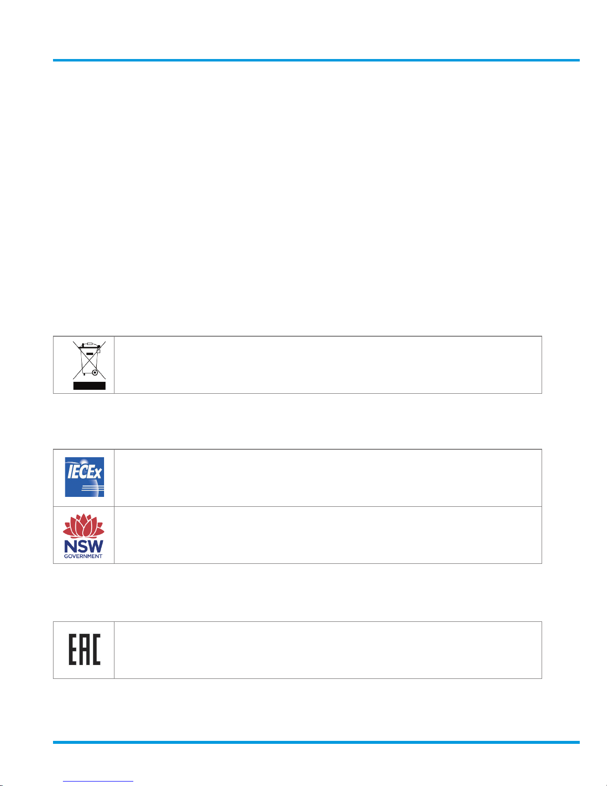
Waste electrical products should not be disposed of with household waste. Please recycle
where facilities exist. Check with your Local Authority or retailer for recycling advice.
IECEx (International) certification for use in underground mines and surface industry with
explosive gas atmospheres in Australia (including Queensland) and New Zealand.
Plant Design Registration for New South Wales in Australia including Performance Testing
for Oxygen, Flammable and Toxic gases.
EAC certification for use in underground mines and surface industry with explosive
gas atmospheres in Eurasian Customs Union (Russia, Kazakhstan Armenia, Belarus,
Kyrgyzstan) including Pattern Approval Certificate for Measuring Instruments.
www.trolex.com
Page 44
44 P5593.1600 Rev B
13.4 India DGMS - PENDING
13.5 South Africa – PENDING
Directorate General of Mines Safety (DGMS) certification for use in coal, metalliferous and
oil mines in India.
MASC (IA) certification for use in underground mines and surface industry with explosive
gas atmospheres in South Africa including Performance Testing for Flammable gases.
www.trolex.com
Page 45

GasHawk TX7000 User Manual
P5593.1600 Rev B 45
Disclaimers
The information provided in this document contains general descriptions and technical
characteristics of the performance of the product. It is not intended as a substitute for and
is not to be used for determining suitability or reliability of this product for specific user
applications. It is the duty of any user or installer to perform the appropriate and complete
risk analysis, evaluation and testing of the products with respect to the relevant specific
application or use. Trolex shall not be responsible or liable for misuse of the information
contained herein. If you have any suggestions for improvements or amendments, or find
errors in this publication, please notify us at [email protected].
No part of this document may be reproduced in any form or by any means, electronic or
mechanical, including photocopying, without express written permission of Trolex.
All pertinent state, regional, and local safety regulations must be observed when installing
and using this product. For reasons of safety and to help ensure compliance with
documented system data, only Trolex or its affiliates should perform repairs to components.
When devices are used for applications with technical safety requirements, the relevant
instructions must be followed.
Trademarks
© 2017 Trolex® Limited.
Trolex is a registered trademark of Trolex Limited. The use of all trademarks in this document
is acknowledged.
Patent pending.
Trolex Ltd, Newby Road, Hazel Grove, Stockport, Cheshire, SK7 5DY, UK
+44 (0) 161 483 1435 [email protected]
www.trolex.com
Page 46

46 P5593.1600 Rev B
www.trolex.com
Page 47

P5593.1600 Rev A 47
GasHawk TX7000 User Manual
www.trolex.com
Page 48

48 P5593.1600 Rev A
www.trolex.com
Trolex Ltd. Newby Road, Hazel Grove, Stockport, Cheshire SK7 5DY, UK
t: +44 (0)161 483 1435 e: [email protected] www.trolex.com
 Loading...