

Page 1

Page 2

Page 3

TX6351 • TX6352 User Manual
P5536.1600 rev A 3
TX6351 • TX6352 Sentro 1 Universal Gas Detector
Contents
1. Product Overview 4
1.1 Operating Features 4
1.2 Application 5
1.3 Product Options 5
1.4 Dimensions 6
1.5 Technical Information 7
1.6 Electrical Details 9
1.7 Sentro eModules 11
2. Certification 18
3. Installation 20
3.1 Safety Precautions 20
3.2 Tools and Test
Equipment Required 21
3.3 Siting Recommendations 21
3.4 Connections 23
3.4.1 0.4 to 2 V Analogue
Output Signal 23
3.4.2 4 to 20 mA Analogue
Output Signal 24
3.4.3 5 to 15 Hz Output Signal 25
3.4.4 Contact Output Signal 25
3.4.5 RS485 Data Output Signal 26
3.5 Connecting in Hazardous
Areas 27
4. Setup and Calibration 28
4.1 Controls and Indicators 28
4.2 Main Display 30
4.3 Security Code Access 31
4.4 Main Menu 32
4.4.1 Calibrate 33
4.4.2 Sentro 1 Setup 36
4.4.3 Output Setup 38
4.4.4 Modbus 41
4.4.5 Module Setup 41
4.4.6 Support 44
5. Diagnostics and
Maintenance 45
5.1 Diagnostic Messages 45
5.2 Maintenance 46
5.3 Maintenance and
Calibration Log 49
5.4 Disposal 50
Disclaimers 51
Trademarks 51
Contact Details 51
Document History 51
www.trolex.com
Page 4
4 P5536.1600 rev A
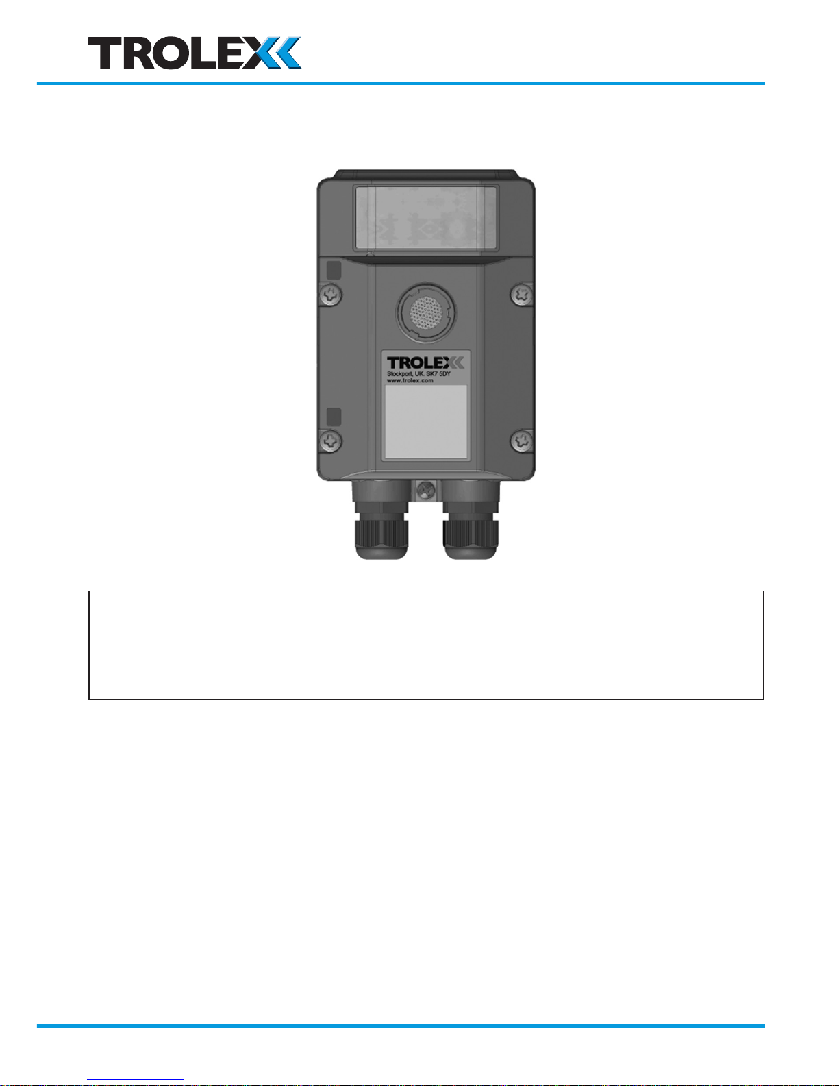
1. Product Overview
TX6351
3/4 wire device with separate output signal and power lines.
Can be used with any Sentro eModule
TX6352
2-wire line powered 4 to 20 mA output signal.
Can ONLY be used with electrochemical Sentro eModules
1.1 Operating Features
• Fixed sensor for detection of Toxic Gases and Flammable Gases
• Exclusive pre-calibrated plug-in gas sensing modules for many types of gas and
climatic conditions
• LCD readout and visual LED alarm indicators
• Choice of supply voltage and output signal format
• Heavy duty housing to IP65, EMC compliant
• STEL and TWA monitoring for selected gases
www.trolex.com
Page 5

TX6351 • TX6352 User Manual
P5536.1600 rev A 5
1.2 Application
Fixed point gas detection for safety monitoring in hazardous areas and general
purpose applications.
Underground Mining and Tunnelling
Ex ia I Ma
TX6351.01
TX6352.01
Supply Voltage: 12 V dc from an
approved power source
Type of protection:
Intrinsically safe. Ex ia
Category: I M1
General Purpose
TX6351.03
TX6352.03
Supply Voltage: 24 V dc
1.3 Product Options
4-wire connection Mining Ex ia General Purpose
0.4 to 2 V output TX6351.01.11 -
4 to 20 mA output TX6351.01.12 TX6351.03.12
5 to 15 Hz output TX6351.01.13 -
Contact output TX6351.01.14 TX6351.03.14
RS485 output TX6351.01.15 TX6351.03.15
*2-wire line powered Mining Ex ia General Purpose
4 to 20 mA output TX6352.01.12 TX6352.03.12
*For use with Toxic Gas Sentro eModules only
www.trolex.com
Page 6
6 P5536.1600 rev A
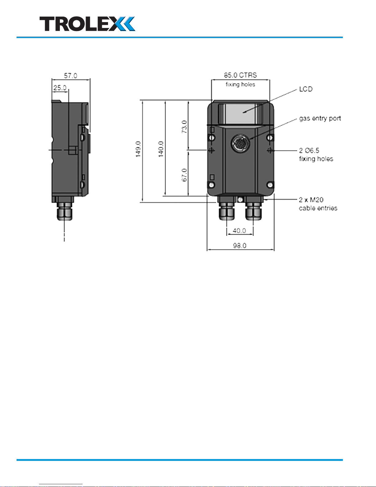
1.4 Dimensions
www.trolex.com
Page 7

TX6351 • TX6352 User Manual
P5536.1600 rev A 7
1.5 Technical Information
Ambient temperature limits -20 to +40°C
Storage temperature -20 to +60°C
Ambient pressure 800 to 1100 mbar
Humidity 90% non-condensing
Protection classification Dust and waterproof to IP65. Gas Port: IP54.
Housing material Reinforced polymer
Nett weight 150 g
Cable entries 2 x M20
Electrical connections 4 mm barrier/clamp terminals
Conductors A maximum of two per terminal
Conductor size A maximum of 2.5 mm²
Terminal torque 2.4 Nm maximum
Information display 128 x 64 dot graphic backlit LCD
Vibration limits Vibration limits (EN 60079-29-1):
• 10 to 30 Hz - 1.00 mm total excursion
• 31 to 150 Hz - 19.6 m/s2 acceleration peak
Impact limits 20 joules (housing)
Calibration and setup Digitally controlled ZERO and SPAN pushbutton
setting
Signal fix The analogue output signal of the sensor is fixed
during calibration to prevent false alarms from
being initiated
Fault indication Under range signal transmitted and fault display
for:
• Loss of communications from the sensing
module
• Sensing module absent for more than 10
seconds
• Sensor over-range protect
Key coding Coding stops prevent insertion of a non-valid
sensing module.
www.trolex.com
Page 8

8 P5536.1600 rev A
Alarms Programmable GENERAL alarms and HIGH
alarms with an LED indicator.
The two adjustable alarm setpoints are preset
during manufacture to default values appropriate
to the type of sensor, determined by the sensing
module being used.
STEL and TWA Automatic calibration of STEL and TWA limits to
EH40 standards.
STEL: Exposure over 15-minute successive
periods
TWA: Exposure over a continuous rolling 8-hour
period
Output signals 0.4 to 2 V
4 to 20 mA
5 to 15 Hz
Dual contacts
RS485 Modbus datacomms
www.trolex.com
Page 9
TX6351 • TX6352 User Manual
P5536.1600 rev A 9
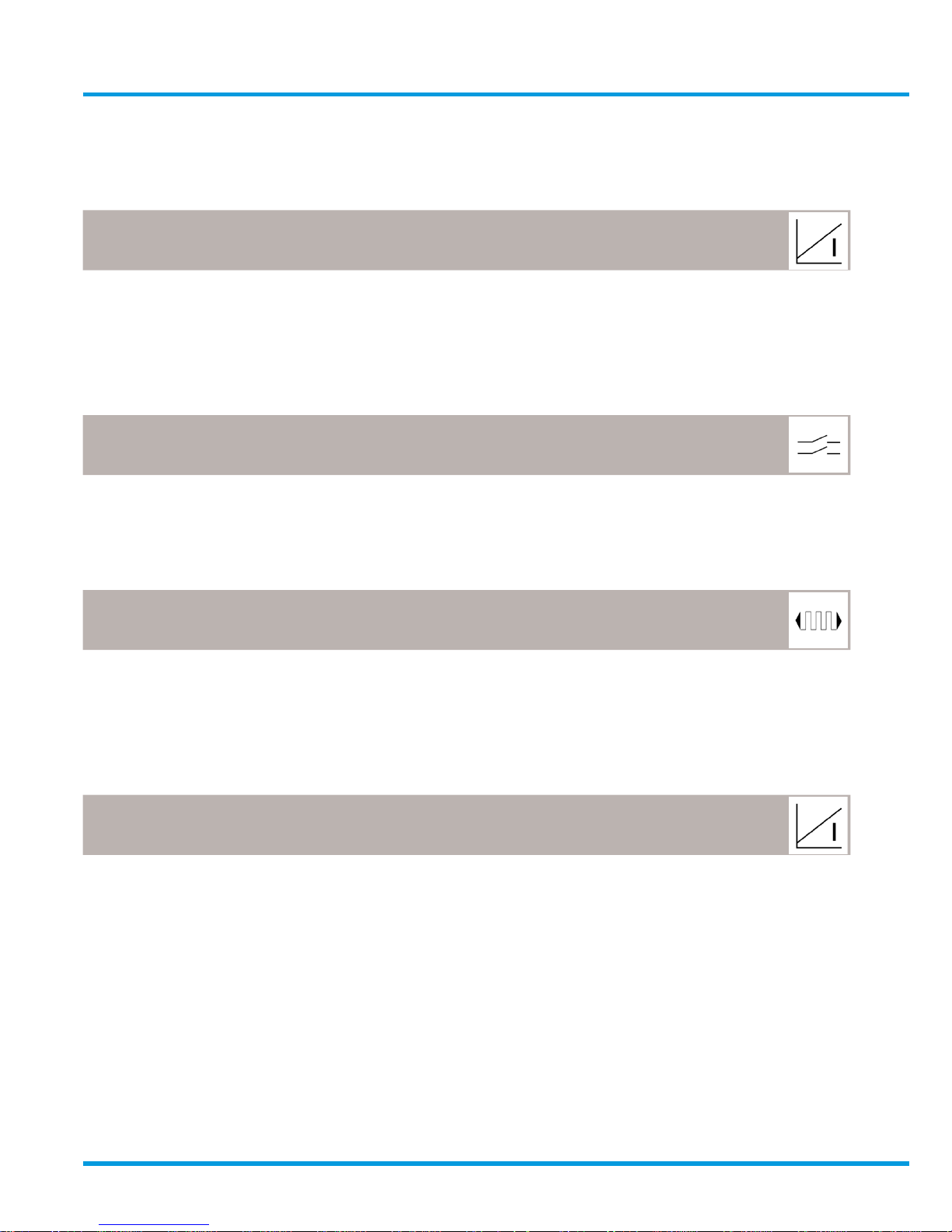
1.6 Electrical Details
General Purpose
TX6351 3/4 wire. Remote powered
4 to 20 mA analogue output
Supply voltage: 18 to 28 V
Max. line load: 500 R at 24 V
Type of sensor: Toxic Flammable Infrared
Supply current: 40 mA 40 mA 60 mA
TX6351 3/4 wire. Remote powered
Dual output contacts
Supply voltage: 20 to 28 V
Type of sensor: Toxic Flammable Infrared
Supply current: 35 mA 45 mA 60 mA
TX6351 3/4 wire. Remote powered
RS485 datacomms output
Supply voltage: 14 to 28 V
Line: Modbus protocol
Type of sensor: Toxic Flammable Infrared
Supply current: 40 mA 40 mA 60 mA
TX6352 2 wire. Line powered
4 to 20 mA analogue output
Supply voltage: 18 to 28 V
Max. Line Load: 300 R
Type of Sensor: Toxic only
www.trolex.com
Page 10
10 P5536.1600 rev A
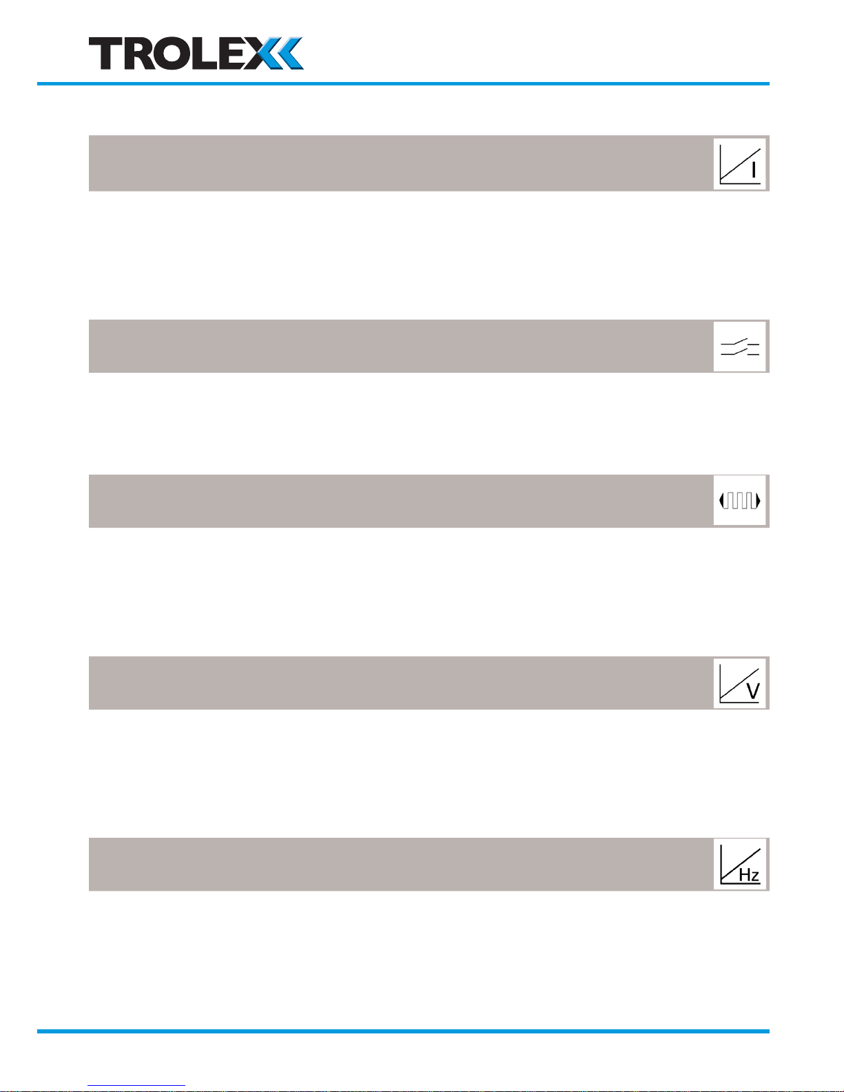
Mining and Tunnelling
TX6351 3/4 wire. Remote powered
4 to 20 mA
Supply voltage: 10 to 14 V
Max. line load: 220 R maximum @ 12 V dc
Type of sensor: Toxic Flammable Infrared
Supply current @ 12 V: 48 mA 70 mA 91 mA
TX6351 3/4 wire. Remote powered
Dual output contacts
Supply voltage: 10 to 14 V
Type of sensor: Toxic Flammable Infrared
Supply current @ 12 V: 60 mA 85 mA 105 mA
TX6351 3/4 wire. Remote powered
RS485 datacomms output
Supply voltage: 10 to 14 V
Line: Modbus protocol
Type of sensor: Toxic Flammable Infrared
Supply current @ 12 V: 25 mA 60 mA 80 mA
TX6351 3/4 wire. Remote powered
0.4 to 2 V analogue output
Supply voltage: 10 to 14 V
Min. line load: 10 KR
Type of sensor: Toxic Flammable Infrared
Supply current @ 12 V: 20 mA 60 mA 80 mA
TX6351 3/4 wire. Remote powered
5 to 15 Hz analogue output
Supply voltage: 10 to 14 V
Max. line load: Opto isolated to 2 mA maximum
Type of sensor: Toxic Flammable Infrared
Supply current @ 12 V: 20 mA 60 mA 80 mA
www.trolex.com
Page 11
TX6351 • TX6352 User Manual
P5536.1600 rev A 11
TX6352 2 wire. Remote powered
4 to 20 mA analogue output
Supply voltage: 10 to 14 V
Max. line load: 90 R
Type of sensor: Toxic only
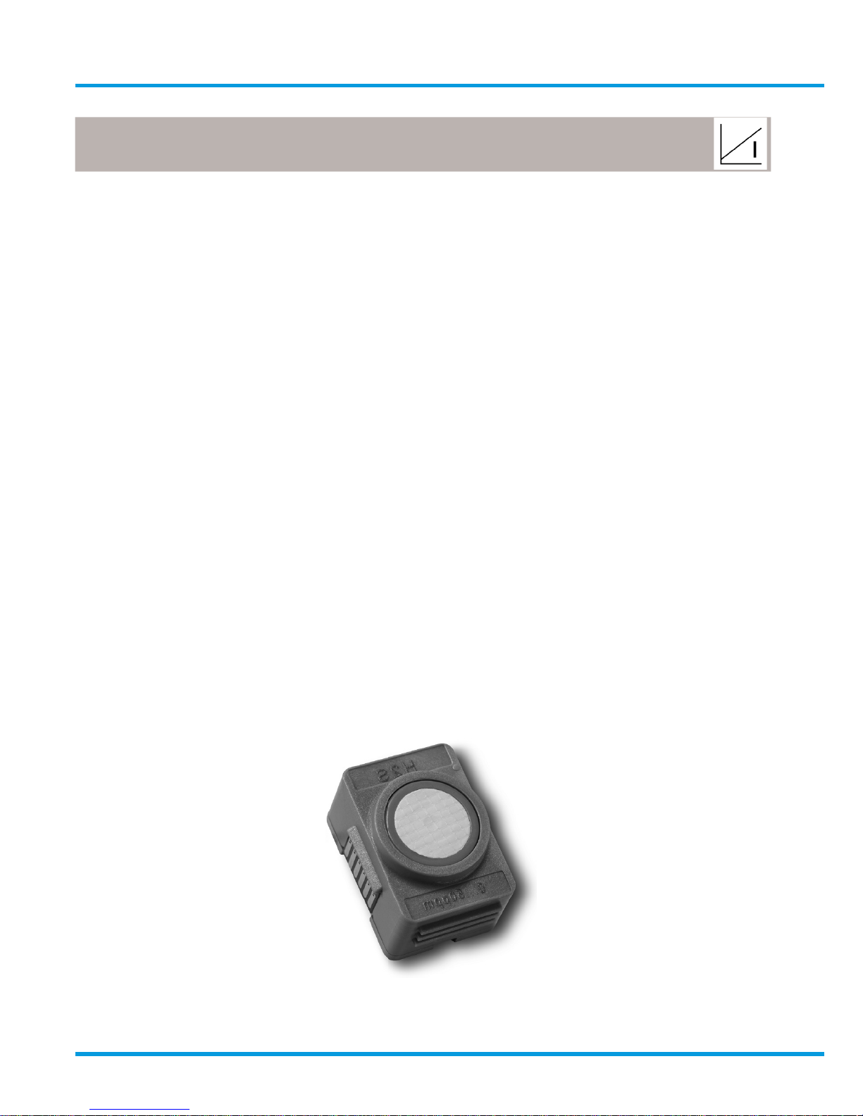
1.7 Sentro eModules
Plug-in pre-calibrated modules with standardised output data.
• Each module stores all the necessary data about its type identification, sensing
range and specific calibration. This data is automatically recognised by Sentro
when the module is loaded into the module bay.
• The modules are pre-calibrated so can be substituted at any time by a
replacement module – usually of the same type, but an alternative may be
inserted if required.
• Insert coding stops to prevent invalid module combinations.
• The sensing module will identify itself when plugged into the sensor housing
and auto configuration will take place.
• All Sentro Modules have two output alarm signals for GENERAL alarm and
HIGH alarm. Default values are entered during manufacture and these can be
changed to preferred values.
• The alarm signals can be set to illuminate built-in flashing LED indicators.
• The signals can operate the two GENERAL alarm and HIGH alarm relays on the
CONTACT OUTPUT version of Sentro 1.
Gas Sensor
www.trolex.com
Page 12
12 P5536.1600 rev A
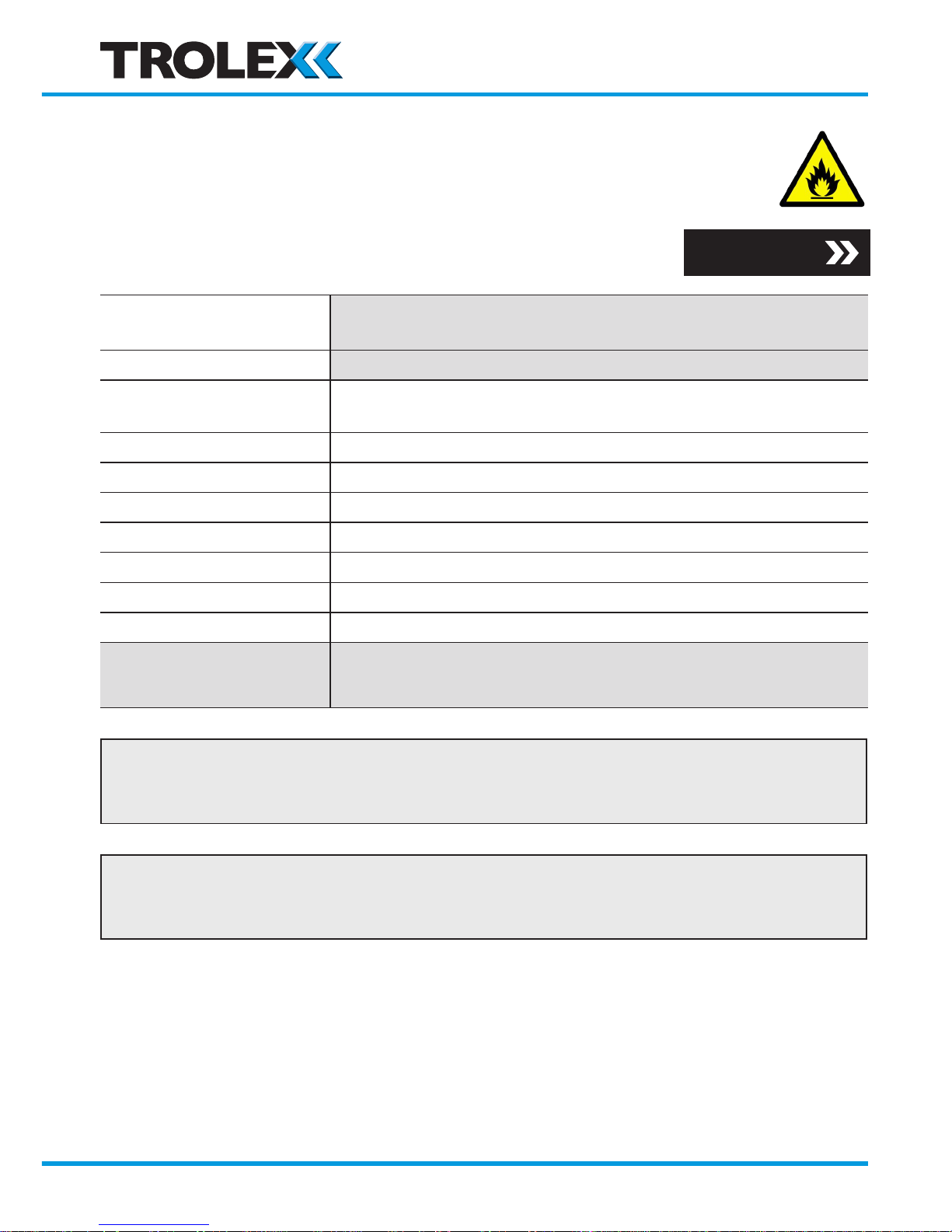
Flammable gases • Poison resistant catalytic sensor
The sensor can be configured to respond to many flammable
gases and vapours. It is usual to calibrate to methane in
terms of %LEL or %volume.
TX6350 .240
.246 .244
Methane CH
4
Methane CH
4
Methane CH
4
Sensing element Poison resistant pellistor with active temperature/humidity
compensation
Sensing range 0 to 100% LEL 0 to 4% v/v 0 to 5% v/v
Linearity Linear up to 3% v/v 3% to 5% ±0.25%
Max. Drift @ 25°C ±0.25% CH4 v/v per month
Response time (T63) <15 secs
Response time (T90) <20 secs
Sensing element life >5 years in clean atmosphere
Warm up time <5 mins in air or 1% v/v CH4 (to 95% of stated accuracy)
GENERAL alarm 10% LEL (.240) 1.25% (.246) 1.25% (.244)
HIGH alarm 20% LEL (.240) 2.00% (.246) 2.00% (.244)
Checkpoint
Not suitable for use with the TX6352 4 to 20 mA two wire, line powered version
of Sentro.
Checkpoint
The pellistor is automatically protected against exposure to excessively high
concentrations of gas.
Section 4.4.5
www.trolex.com
Page 13
TX6351 • TX6352 User Manual
P5536.1600 rev A 13
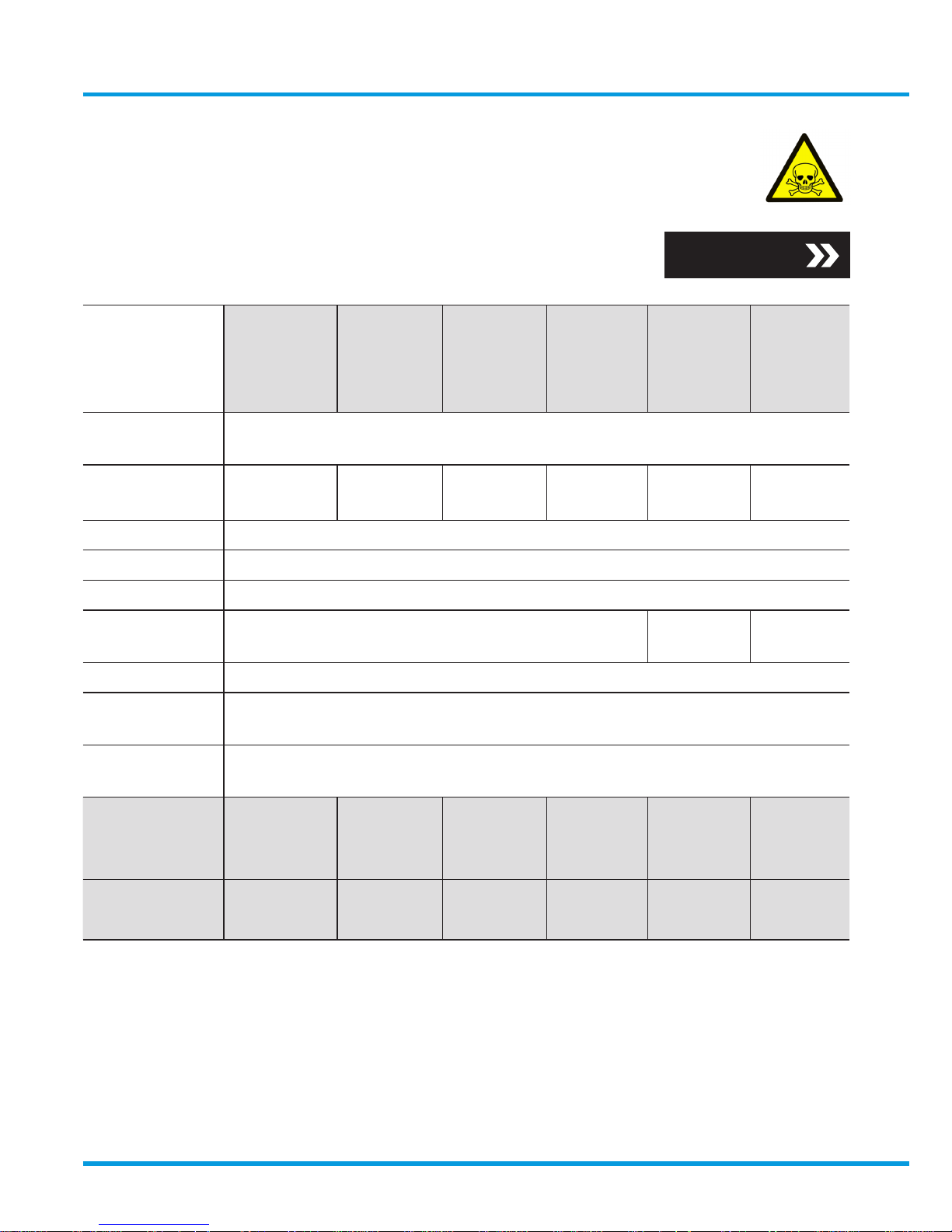
Toxic gases • Electrochemical cells
Selected toxic gas modules are equipped with automatic
STEL/TWA calculation in accordance with EH40.
TX6350 .250.50 .250.250 .250.300 .250.500 .251 .252
Carbon
Monoxide
CO
Carbon
Monoxide
CO
Carbon
Monoxide
CO
Carbon
Monoxide
CO
Hydrogen
Sulphide
H2S
Sulphur
Dioxide
SO
2
Sensing
element
Electrochemical cell
Sensing
range
0 to
50 ppm
0 to
250 ppm
0 to
300 ppm
0 to
500 ppm
0 to
50 ppm
0 to
20 ppm
Linearity ±2% FS
Drift 2% per month
Repeatability ±2%
Response
time T63%
<20 secs <30 secs <20 secs
Operating life 2 years
Relative
humidity
15 to 90% non-condensing
Operating
temperature
-10 to +40°C
GENERAL
alarm
15 ppm 25 ppm 25 ppm 25 ppm 5 ppm 5 ppm
HIGH alarm 30 ppm 100 ppm 100 ppm 200 ppm 10 ppm 10 ppm
STEL & TWA
200 ppm 200 ppm 200 ppm 200 ppm 10 ppm 5 ppm
30 ppm 30 ppm 30 ppm 30 ppm 5 ppm 2 ppm
Section 4.4.5
www.trolex.com
Page 14
14 P5536.1600 rev A
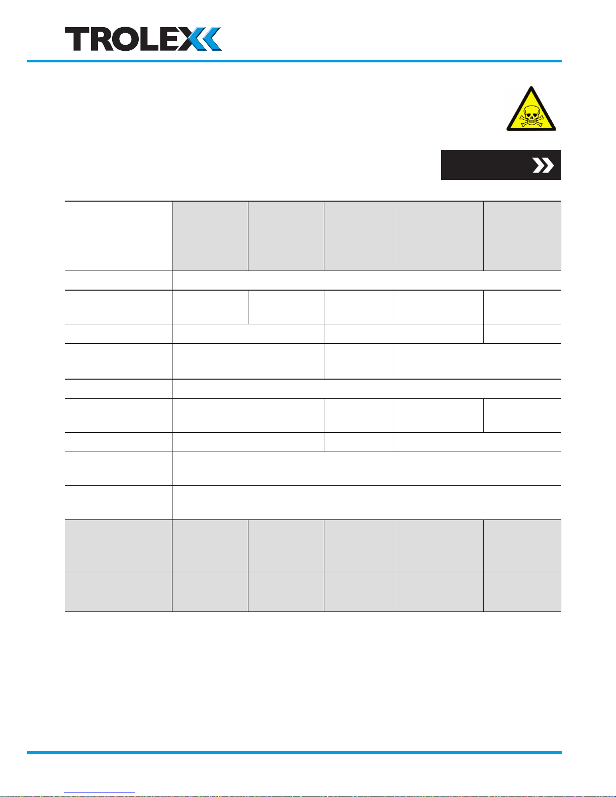
Toxic gases • Electrochemical cells - continued
Selected toxic gas modules are equipped with automatic
STEL/TWA calculation in accordance with EH40.
TX6350 .254 .254.10 .257 .259 .261
Nitrogen
Dioxide
NO
2
Nitrogen
Dioxide
NO
2
Oxygen
O
2
Nitric Oxide
NO
Hydrogen
H
2
Sensing element Electrochemical Cell
Sensing range 0 to 20 ppm 0 to 10 ppm 0 to 25% 0 to 50 ppm
0 to
1000 ppm
Linearity ±2% FS ±5% FS ±2% FS
Drift 2% per month
10%
per year
2% per month
Repeatability ±2%
Response time
T63%
<20 secs N/A <20 secs <70 secs
Operating life 2 years 1 year 2 years
Relative
humidity
15 to 90% non-condensing
Operating
temperature
-10 to +40°C
GENERAL
alarm
5 ppm 2.5 ppm 19% (under) 5 ppm 250 ppm
HIGH alarm 10 ppm 5 ppm 23% (over) 20 ppm 500 ppm
STEL & TWA
5 ppm 5 ppm N/A 10 ppm N/A
3 ppm 3 ppm N/A 3 ppm N/A
Section 4.4.5
www.trolex.com
Page 15

TX6351 • TX6352 User Manual
P5536.1600 rev A 15
Checkpoint
Toxic gas Sentro eModules have a very low power consumption, enabling 4 to 20 mA two
wire TX6352 line-powered version of Sentro to be used.
Checkpoint
All values listed are nominal and slight variations may occur depending upon operating
conditions.
• The natural level of oxygen available in the atmosphere is influenced by relative
humidity and temperature. The oxygen sensor will react to these changes.
• Sudden changes in atmospheric pressure will also cause temporary instability in
electrochemical sensors which may exceed 60 seconds.
• Long periods of use in extremely high or low humidity may affect the response of the
sensor and shorten the life of electrochemical sensors.
• Nitric oxide sensors must be continuously powered to maintain calibration stability.
If power has been absent for more than 10 minutes, it may take 24-48 hours for the
sensor to restore stability. Do not calibrate until the output signal is steady.
• The presence of high levels of carbon dioxide (over 5%) may have a minor effect on
the accuracy of the oxygen sensor.
Checkpoint
Periodic calibration of the gas sensor should be carried out whilst it is in service. For
oxygen and carbon monoxide gas sensors Trolex recommends that this is carried out
every 3 weeks. For other gas sensors Trolex recommends that this is carried out in
accordance with best practice for the industry where the gas sensor is being used, and
should take into consideration local operating conditions.
www.trolex.com
Page 16
16 P5536.1600 rev A
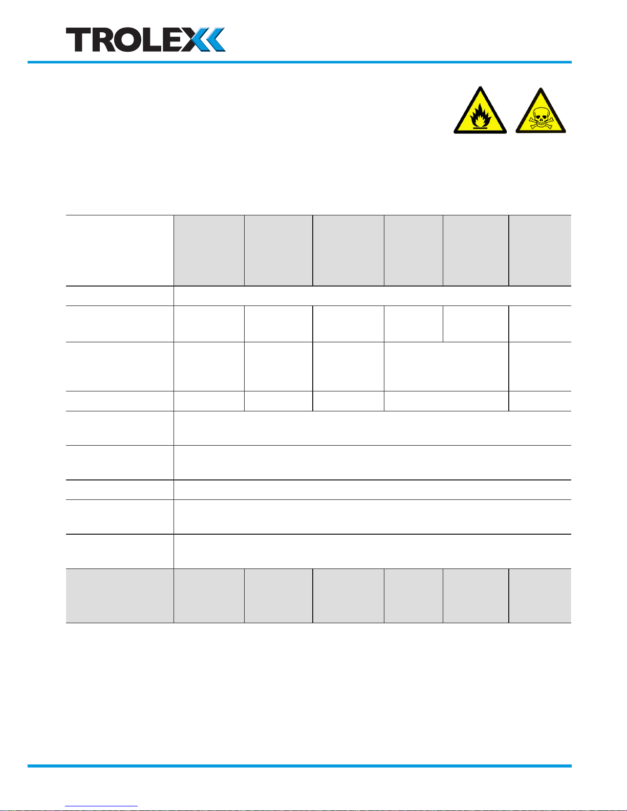
Carbon Dioxide/Methane Gases • Infrared sensor
The sensor is highly specific to the selected gas and exhibits
consistent sensing accuracy with superior long-term stability.
The linear response means that it can be calibrated for low gas
concentrations and high concentrations up to 100% by volume.
TX6350
.243 .245 .242 .253 .278 .279
Methane
CH
4
Methane
CH
4
Methane
CH
4
Carbon
Dioxide
CO
2
Carbon
Dioxide
CO
2
Carbon
Dioxide
CO
2
Sensing element
Infrared
Sensing range
0 to
5% v/v
0 to
100% LEL
0 to
100% v/v
0 to
2% v/v
0 to
5% v/v
0 to
100% v/v
Zero drift
±0.05% v/v
per month
±1% LEL
per month
±0.5% v/v
per month
±0.05% v/v per
month
±1%
v/v per
month
Repeatability
±0.1% v/v ±2% LEL ±2% v/v ±0.05% v/v ±2% v/v
Response time
T63%
<15 secs
Response time
T90%
<30 secs
Operating life
<5 years
Relative
humidity
15 to 90% non-condensing
Operating
temperature
-10 to +40°C
GENERAL
alarm
1.25% v/v 10% LEL 25% v/v 0.5% v/v 1.25% v/v 25% v/v
HIGH alarm
2.5% v/v 20% LEL 50% v/v 1 % v/v 2.5% v/v 50% v/v
www.trolex.com
Page 17

TX6351 • TX6352 User Manual
P5536.1600 rev A 17
Checkpoint - Carbon Dioxide Sensors
Normal atmosphere contains carbon dioxide which will affect the sensor signal so
nitrogen gas must be used to accurately calibrate the zero value. Power should
be applied to the sensor and the nitrogen applied for at least 5 minutes to ensure
that the sensor has stabilised.
Checkpoint
Not suitable for use with the TX6352 4 to 20 mA two wire, line powered version
of Sentro 1.
www.trolex.com
Page 18
18 P5536.1600 rev A
2. Certification
2.1 Europe (ATEX)
Ex certified for use in M1 applications:
Europe (ATEX):
TX6351.01i.xx/TX6352.01i.xx
Ex Certificate number: SIRA09ATEX2352X
Ex Certification code: I M1 Ex ia I Ma (20°C ≤ Ta ≤ +40°C)
Important – Prior to installation, it is essential that the user
refers to the relevant certificate to ensure that the termination
and cable parameters are fully complied with and are
compatible with the application. Copies of certificates
are available from www.trolex.com.
ATEX directive 94/9/EC
EMC directive 2004/108/EC
Special Conditions for Safe Use
The minimum ingress protection stated in the Ex-certificates for the Sentro
eModules are satisfied when mounted in the Sentro Gas Detector, as are the
conditions for impact protection and external fuse protection in the case of the
infrared eModule.
The Ex-certificates associated with the Sentro Modules are listed below:
eModule Flammable Group I SIRA 10ATEX2046U
eModule Toxic Group I SIRA 08ATEX2097U
eModule Infrared Group I SIRA 10ATEX2356U
www.trolex.com
Page 19
TX6351 • TX6352 User Manual
P5536.1600 rev A 19
2.2 Russia (Customs Union)
Ex Certificate number: TC RU C-GB.ГБ05.B.00616
Ex Certification code: PO Ex ia I Ma X
Conditions of Use
Prior to installation, it is essential that user refers to the above certificate for any
specific conditions of use. The user must ensure that the termination and cable
parameters are fully complied with and are compatible with the application. Copies
of certificates are available from Trolex.
2.3 South Africa (MASC)
Ex Certificate number: MASC M/11-419X
Ex Certification code: Ex ia I Ma
General Conditions for Safe Use
Prior to installation, it is essential that user refers to the above certificate to
ensure that the termination and cable parameters are fully complied with and are
compatible with the application. Copies of certificates are available from Trolex.
2.4 India (CIMFR)
Test report number: CIMFR/TC/P/H738
www.trolex.com
Page 20
20 P5536.1600 rev A
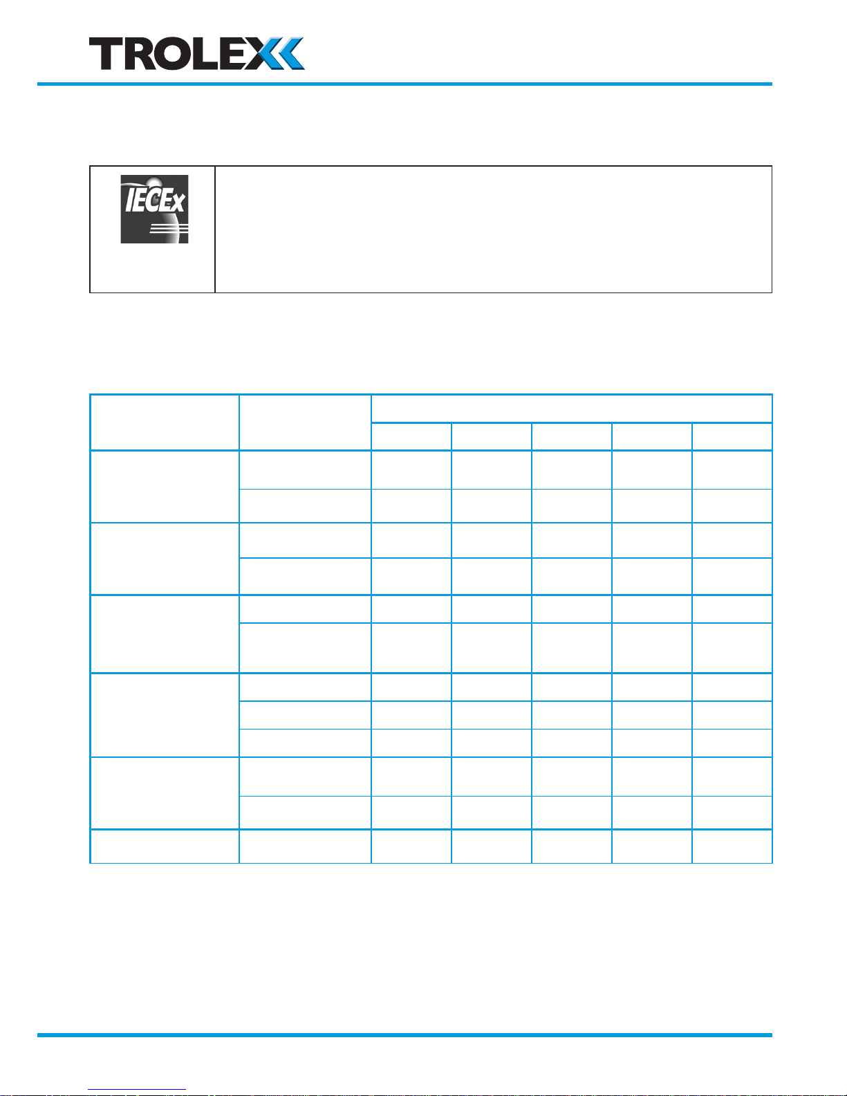
2.5 Australia (IECEx)
Ex certified for use in Ma applications:
Australia (IECEx):
TX6351.01i.xx/TX6352.01i.xx
Ex Certificate number: IECEx ITA 14.0006X
Ex Certification code: Ex ia I Ma
Conditions of Safe Use
The following safety parameters are applicable to the Sentro 1 Sensor/Transmitters:
Model
Terminals
Input Parameters
Ui li Ci Li Pi
TX6351.01i.11
and
TX9081.01i.11
5 WRT 6 14.4 V * 1 * 2 * 3 -
1 WRT (2 or 3) - - - - -
TX6351.01i.12
and
TX9081.01i.12
5 WRT 6 14.4 V * 1 * 2 * 3 -
1 WRT (2 or 3) - - - - -
TX6351.01i.15
and
TX9081.01i.15
5 WRT 6 14.4 V * 1 * 2 * 3 -
1 WRT 2
2 WRT 3
- - - - -
TX6351.01i.14
and
TX9081.01i.14
5 WRT 6 14.4 V * 1 * 2 * 3 -
1 WRT 2 30 V * 1 0 0 -
3 WRT 4 30 V * 1 0 0 -
TX6351.01i.13
and
TC9081.01i.13
5 WRT 6 14.4 V * 1 * 2 * 3 -
1 WRT 2 16.5 V - 0 0 2.5 W
TX6352.01i.12 1 WRT 2 14.4 V * 1 * 2 * 3 -
www.trolex.com
Page 21

TX6351 • TX6352 User Manual
P5536.1600 rev A 21
Model
Terminals
Output Parameters
Uo lo Po Co Lo * 5
TX6351.01i.11
and
TX9081.01i.11
5 WRT 6 - - - - -
1 WRT (2 or 3) 14.4 V 40 mA
135 mW
* 4 292 mH
TX6351.01i.12
and
TX9081.01i.12
5 WRT 6 - - - - -
1 WRT (2 or 3) 14.4 V 477 mA 1.72 W * 4 2.1 mH
TX6351.01i.15
and
TX9081.01i.15
5 WRT 6 - - - - -
1 WRT 2
2 WRT 3
5.88 V 66 mA 97 mW * 4 26 mH
TX6351.01i.14
and
TX9081.01i.14
5 WRT 6 - - - - -
1 WRT 2 0 0 0 0 0
3 WRT 4 0 0 0 0 0
TX6351.01i.13
and
TC9081.01i.13
5 WRT 6 - - - - -
1 WRT 2 0 0 0 0 0
TX6352.01i.12 1 WRT 2 - - - 0 0
* 1 Ii Not critical
* 2 Ci Ci = 0, unless an rModule is connected to the Sentro 1, then
Ci = 0.38 μF plus the Ci of the external sensors connected to the
rModule
* 3 Li Total Li of all external sensors and equipment connected to the rModule
* 4 Co 1 μF, unless the conditions stated in 60079-11 2011, Clause 10.1.5.2
part b can be satisfied
WRT With Respect To
General Conditions for Safe Use
Prior to installation, it is essential that user refers to the above certificate to
ensure that the termination and cable parameters are fully complied with and are
compatible with the application. Copies of certificates are available from Trolex Ltd.
www.trolex.com
Page 22

22 P5536.1600 rev A
3. Installation
3.1 Safety Precautions
Hazardous areas
Do not disassemble the sensor whilst in the hazardous area or use a sensor that
has a damaged housing in the hazardous area.
Evacuation
If a dangerous level of gas concentration is detected by the instrument, leave the
area immediately.
Operating Life of Gas Sensors
Electrochemical cells contain an electrolyte that is gradually consumed during use.
The average life is about two years, dependant upon the duty cycle. The response
should be checked at regular intervals.
Sensitivity
Electrochemical cells for toxic gases can be affected by other interfering gases
which may displace the subject gas being monitored. Steam laden atmospheres
and condensation can also reduce the sensitivity.
Flammable
Be aware that some toxic gases are also ‘flammable’ at high percentage
concentrations.
Operating Limits of Catalytic Combustion Sensors
Catalytic combustion sensors positively detect the presence of flammable gas.
They rely upon the presence of oxygen in the atmosphere and should only be used
for gas concentration up to the Lower Explosive Limit (LEL).
After this point, the output becomes non-linear and may erroneously indicate
that the gas concentration is below the LEL. They should not be used in oxygen
enriched or deficient atmospheres.
www.trolex.com
Page 23

TX6351 • TX6352 User Manual
P5536.1600 rev A 23
Discrimination
Catalytic combustion sensors can detect a wide range of flammable gases but they
cannot discriminate between individual gases. They will respond to most, or all,
of the flammable components present in the atmosphere without distinguishing
between them.
Infrared sensors are highly specific to the defined gas type and may not respond to
other similar gases.
Contamination
The response of catalytic combustion gas sensors can be affected by air borne
contaminants which will reduce the sensitivity. Substances such as silicones, tetraethyl
lead, sulphur compounds and phosphate esters can cause permanent degradation
(poisoning). Halogenated hydrocarbons may also cause temporary inhibition.
Interference
If the atmosphere to be monitored contains a gas that dilutes or displaces the
air, this may reduce the response of catalytic sensors. Similarly, steam laden
atmospheres and condensation can reduce the stability.
High Concentrations of Flammable Gas
Exposure of low concentration catalytic combustion sensors to concentrations of
flammable gas greater than the LEL can affect the sensitivity and zero stability of
catalytic elements and the calibration should be checked after such an exposure.
Toxicity
Be aware that most flammable gases and vapours are also toxic at low
concentrations of LEL.
3.2. Tools and Test Equipment Required
No special tools are needed.
3.3. Siting Recommendations
Location of Gas Detectors
Each installation needs to be considered in its own right, with reference to safety
authorities and in compliance with mandatory local safety regulations. The sensor
must be operated in accordance with the User Manual to maintain safety, reliability
and to preserve safety integrity where applicable.
www.trolex.com
Page 24

24 P5536.1600 rev A
It is important that sensors are located in positions determined in consultation
with those who have specialised knowledge of the plant or installation and of the
principles of gas dispersion. Reference should also be made to those responsible
for the engineering layout and topology of the plant as they will be most familiar
with the nature of the potential dangers and the most likely sources of gas release.
It is also important to recognise that the characteristics of the gas source can be
influenced by many factors; including the relative density or buoyancy of the gas,
the pressure at the point of release, the ambient temperature and the ventilation of
the site.
Sensor coverage cannot be simply expressed in terms of ‘number per unit area’.
Sensors need to be sited where they are capable of monitoring those parts of a
plant where gas may accumulate or where a source of gas release is expected
to occur. This way, the earliest possible warning of a gas release can be given to
initiate shutdown functions, alarm functions or safe evacuation of the premises.
Sensor Management
A very important part of an efficient gas monitoring system is the training of
plant personnel in operation and maintenance of the sensors and the complete
monitoring system. Training can be provided by qualified Trolex application
engineers.
Once a sensor installation is complete, the sensor locations and types should be
formally recorded and a planned test and maintenance procedure instituted.
STEL and TWA
Selected gas sensors are equipped to automatically calculate STEL and TWA limits
in accordance with EH40 standards.
If the facility is selected for use, ensure that all accumulated data is reset to zero
before the commencement of a working period.
www.trolex.com
Page 25
TX6351 • TX6352 User Manual
P5536.1600 rev A 25
3.4 Connections
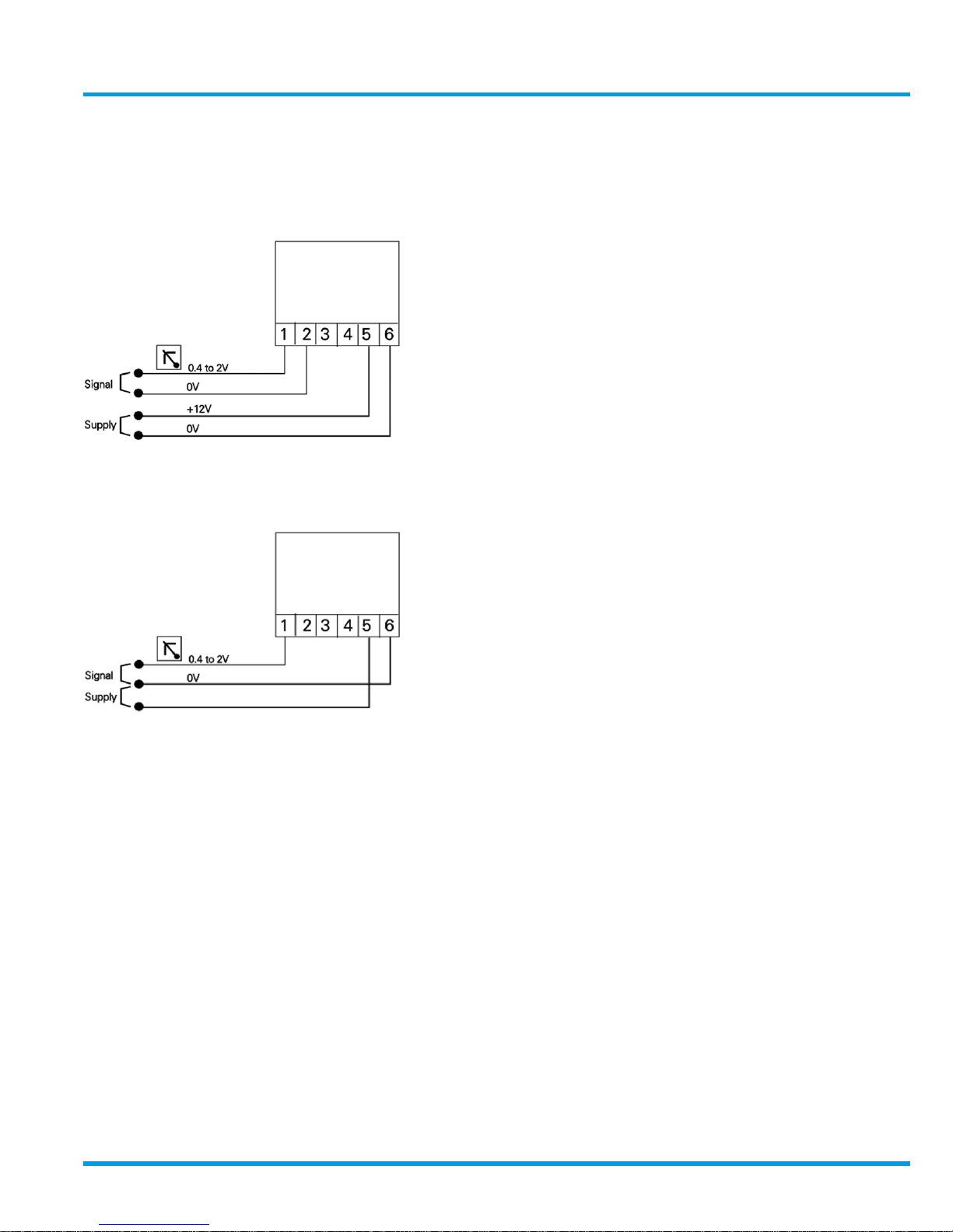
3.4.1 0.4 to 2 V Analogue Output
Signal
A low impedance two-wire voltage output
signal requiring a separate power supply to
the sensor.
12 V dc power can usually be derived from
the monitoring instrument being used.
The connection configuration works well up
to 5-100 m distance between the sensor and
the monitoring equipment, dependent on
cabling and sensor current consumption.
Both the signal and the power supply to the
sensor are being carried in the common 0 V
conductor so at some point – influenced by
the length of the cable and the resistance of
the cable cores – the current flowing in the
0 V conductor will impose an unacceptable
voltage error onto the signal.
This effect can be reduced on long distance
connections by increasing the size of the
cable cores, or even better, by running a
separate 0 V conductor to power the sensor
enabling operating distances up to 1,000 m.
Alternatively, the sensor may be powered by
a suitable power source close by.
www.trolex.com
Page 26
26 P5536.1600 rev A
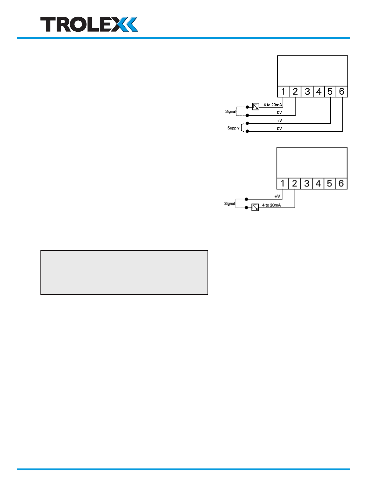
3.4.2 4 to 20 mA Analogue Output
Signal
TX6351
The output signal from terminals 1 and 2 is
a conventional 4 to 20 mA two wire current
regulated signal loop.
TX6352 (Toxic Sentro eModules only)
The output signal from terminals 1 and 2 is
a conventional 4 to 20 mA two wire current
regulated signal loop.
Electrochemical cells have very low power
consumption so the same loop can be used
to also power the sensor. No separate
power supply is needed.
Checkpoint
The TX6352 version of Sentro is NOT
suitable for flammable gas and infrared
Sentro eModules.
www.trolex.com
Page 27
TX6351 • TX6352 User Manual
P5536.1600 rev A 27
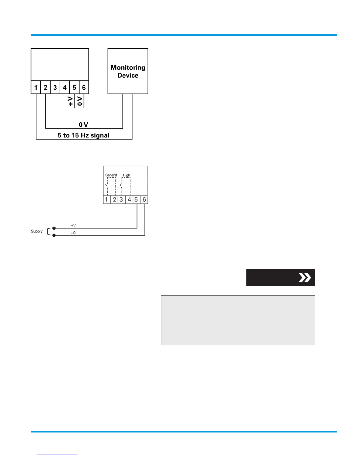
3.4.3 5 to 15 Hz Output Signal
A square wave, frequency variable output
that is proportional to the measured value.
A pull up resistor may be required at the
monitoring device.
3.4.4 Contact Output Signal
Dual independent output contacts for remote
signalling and control. Setpoint values for
GENERAL alarm and HIGH alarm are setup
during manufacture to prescribed levels
appropriate to the type of gas intended to be
monitored; determined by the gas sensing
module.
The setpoints may be adjusted to preference.
Checkpoint
The relay contacts are clearance
compatible for use with other intrinsically
safe circuits emanating from different IS
power sources.
Section 4.4.3
www.trolex.com
Page 28
28 P5536.1600 rev A
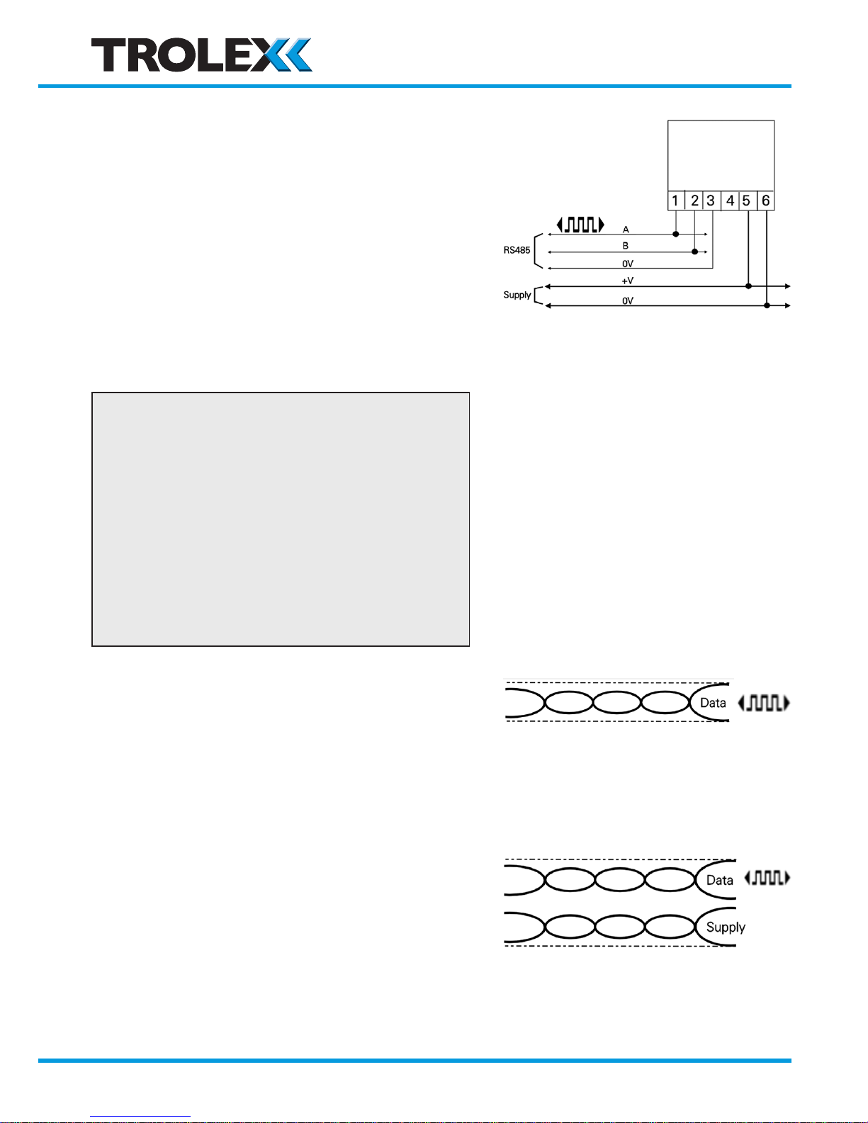
3.4.5 RS485 Data Output Signal
RS485 serial data output with analogue
signal intelligence.
Use in conjunction with a PC for data display
and setpoint alarm warnings.
Up to 32 sensors acting as slaves can
communicate with the master unit on a
single data cable.
The address code of the sensor is marked on
the duty label of the sensor.
Physical layer: RS485
Protocol: Trolex proprietary
Connection mode: Modbus
Number of points: 32
Maximum distance: 1,000 m
Recommended cable (specified in BS5308
Part 1) for locally powered sensors:
• 1 twisted pair
• 0.5 mm
2
• Overall screen
Recommended cable for sensors that are
powered through the data cable:
• 2 twisted pair
• 0.5 mm
2
• Individual/overall screen
www.trolex.com
Page 29
TX6351 • TX6352 User Manual
P5536.1600 rev A 29
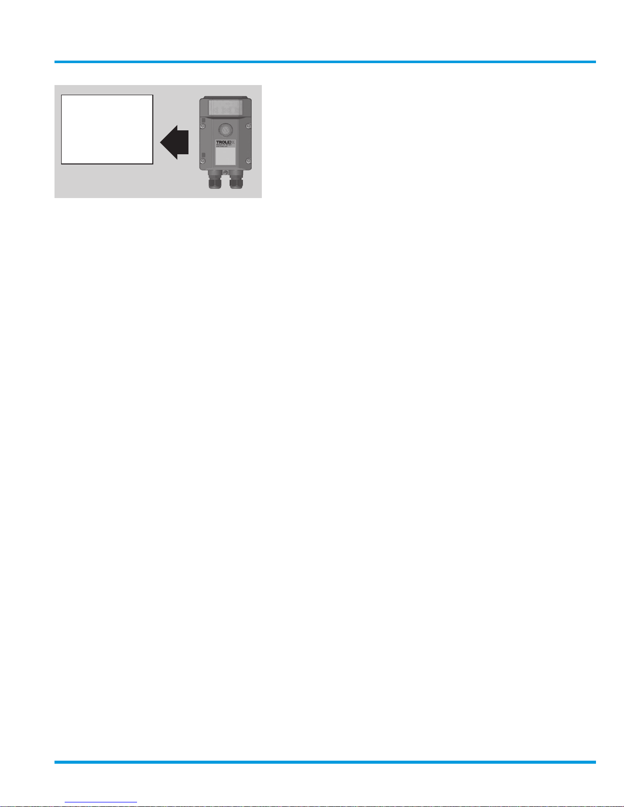
3.5 Connecting in Hazardous
Areas
Certified Intrinsically Safe for use in mining
hazardous areas, category M1, when used
with approved monitoring apparatus.
Power for the sensor must be derived from
an approved 12 V dc power supply e.g.
TX6642 Intrinsically Safe Power Supply or
approved apparatus.
The installation must be in accordance with
the Sentro certification parameters.
Intrinsically
Safe
Apparatus
Hazardous Area
www.trolex.com
Page 30
30 P5536.1600 rev A
4. Setup and Calibration
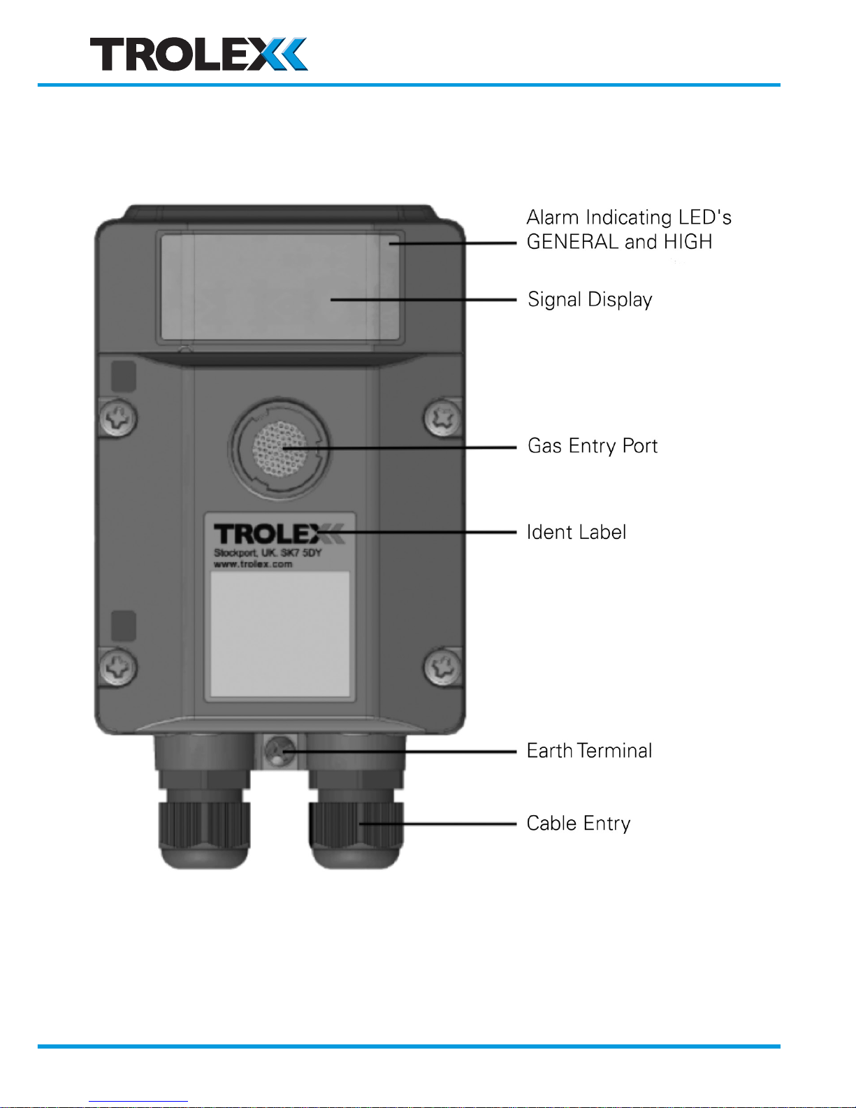
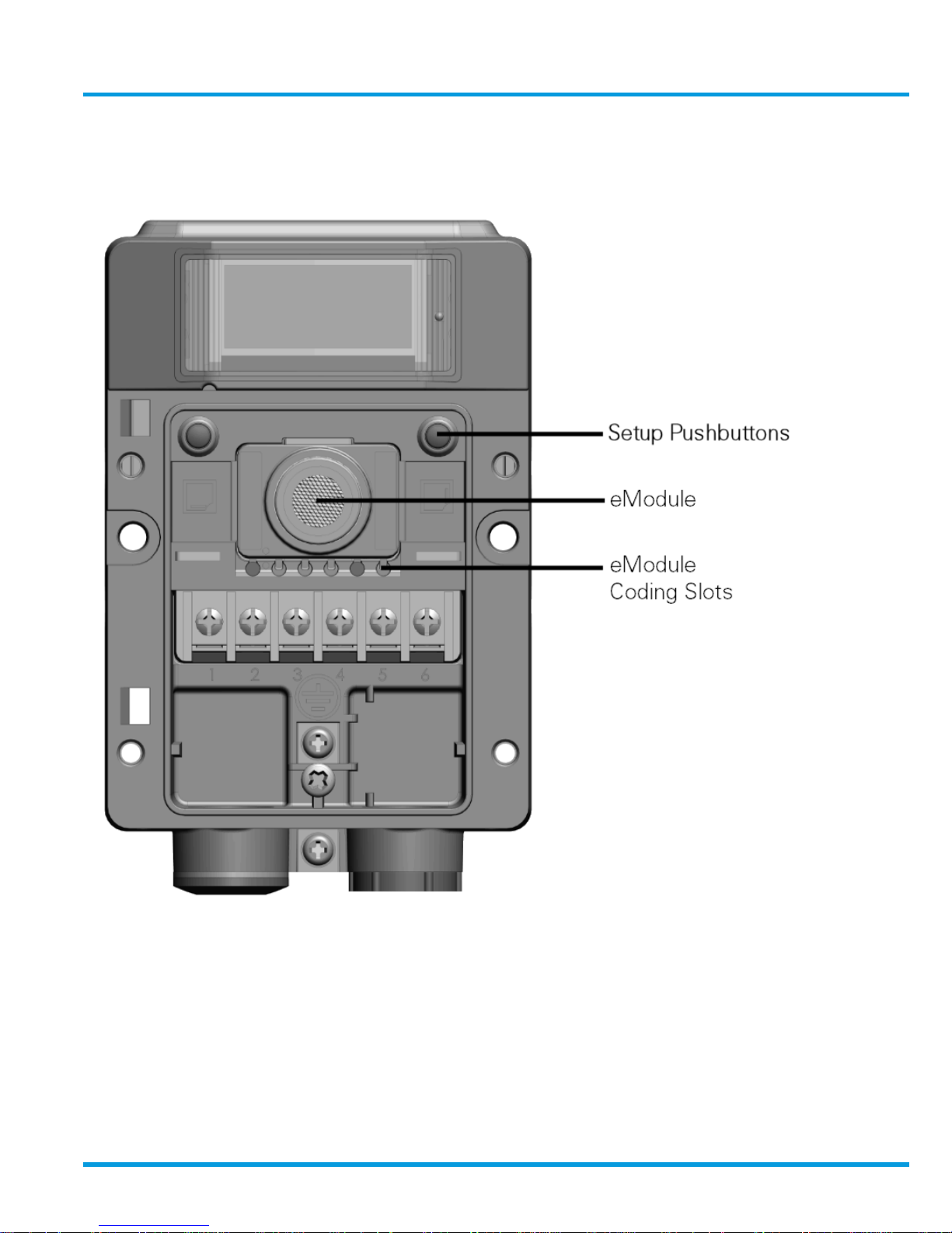
4.1 Controls and Indicators
www.trolex.com
Page 31
TX6351 • TX6352 User Manual
P5536.1600 rev A 31
www.trolex.com
Page 32
32 P5536.1600 rev A
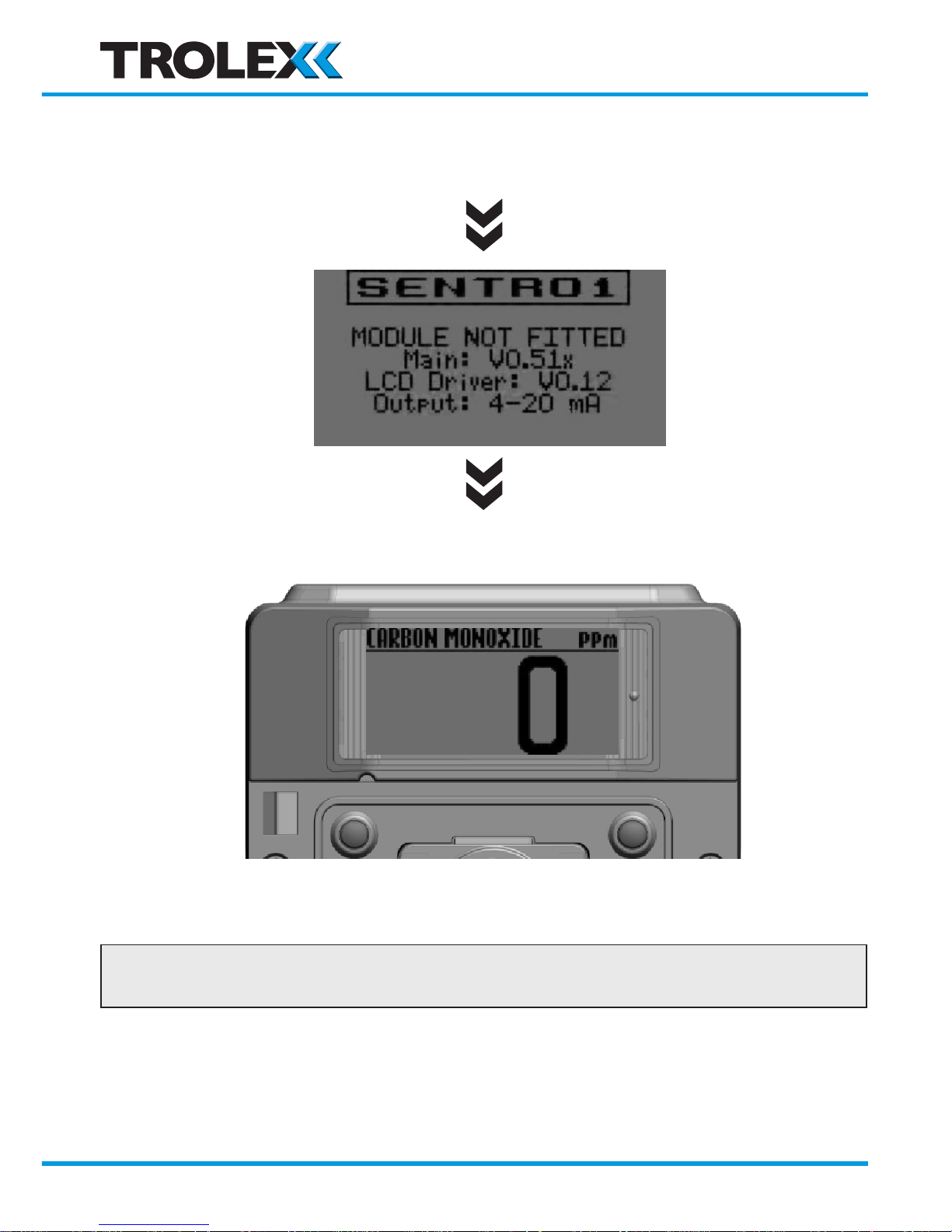
4.2 Main Display
Power On
NEXT/FUNCTION SELECT/CHANGE
Checkpoint
Next/Function is the Left hand key (L) and Select/Change is the Right hand key (R).
www.trolex.com
Page 33
TX6351 • TX6352 User Manual
P5536.1600 rev A 33
Main Menu
Press the R key to enter the Main Menu
Checkpoint
The front cover of Sentro may be safely
removed, for setup in a hazardous area,
even with the power applied.
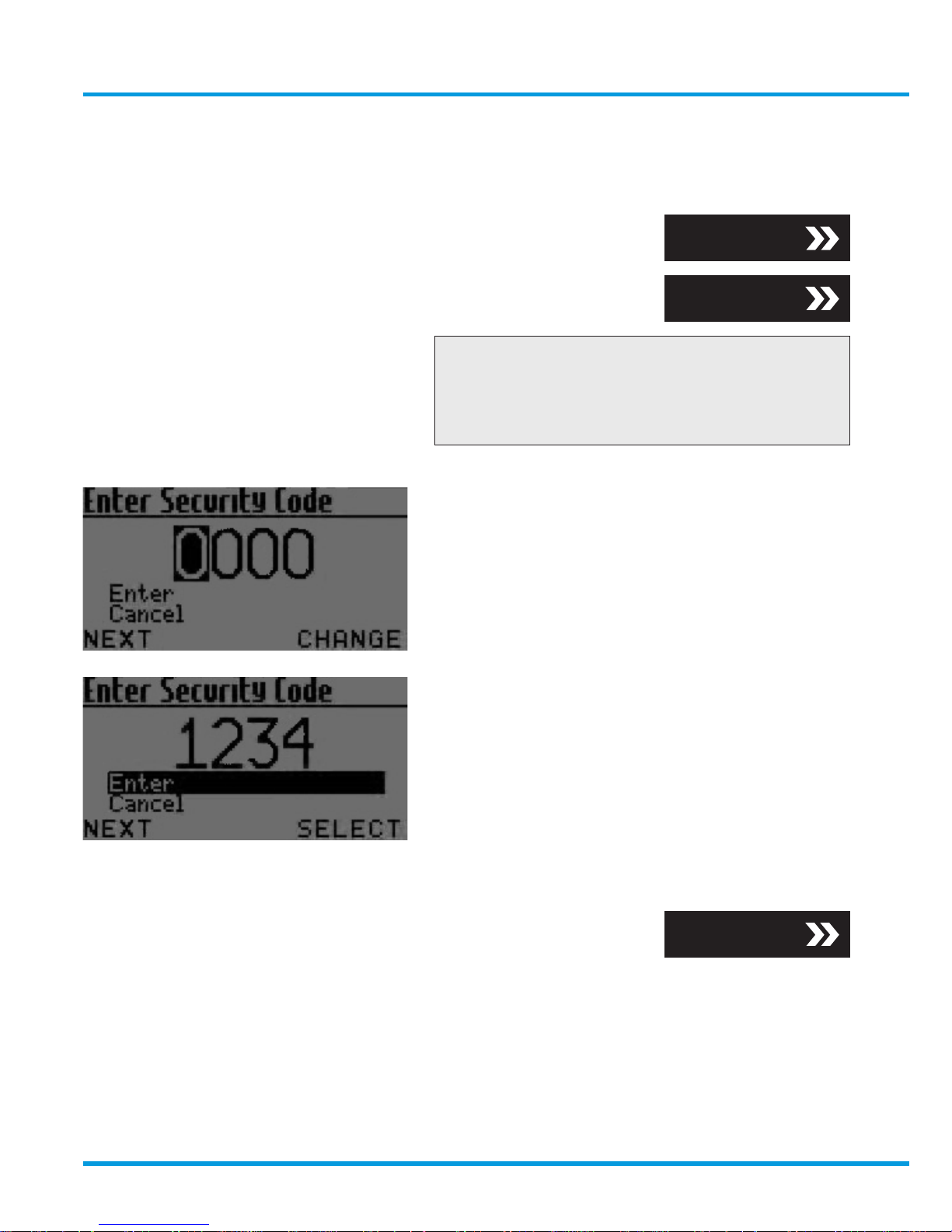
4.3 Security Code Access
A security code may be requested:
Press the R key to change the digit
Use the L key to increment the digits
Use the R key to select Enter and return to
the Main Menu
Section 4.4
Section 4.3
Section 4.4
www.trolex.com
Page 34
34 P5536.1600 rev A
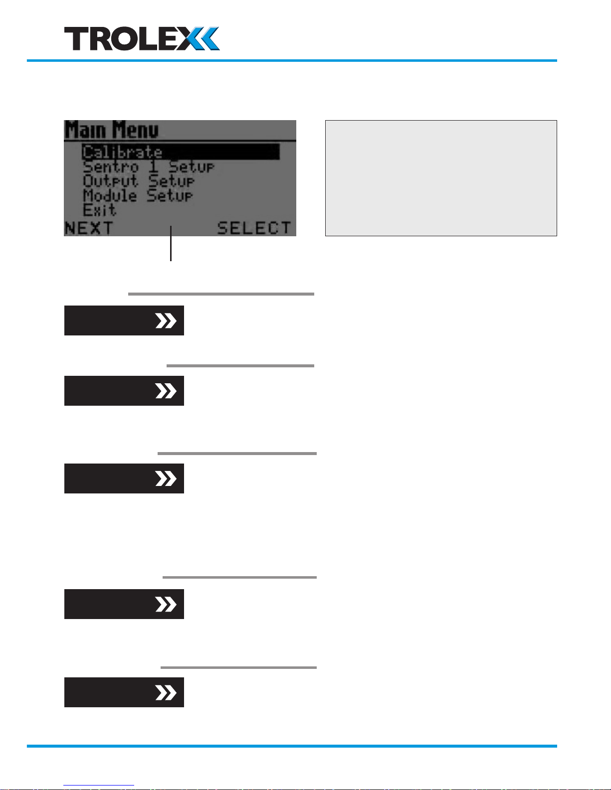
4.4 Main Menu
Prompt Bar
Calibrate
Sentro 1 Setup
Output Setup
Modbus Setup
Module Setup
Checkpoint
Sentro will automatically return to
the Main Display if no commands are
given within 1 minute. The time limit is
extended to 8 minutes during calibration
to allow the gas value to stabilise.
Section 4.4.1
Section 4.4.2
Section 4.4.3
Section 4.4.4
Section 4.4.5
Zero
Set Test Gas
Span
System Information
Display Setup
Alert Setup
Set Security Code
Exit
Output Information
Trim Output Zero
Trim Output Span
Reset Output
Set Relay 1 Mode
Set Relay 2 Mode
Exit
Modbus Address
Baud Rate
TX On Delay
TX Off Delay
Exit
Setpoint 1
Setpoint 2
STEL/TWA
Exit
(L) (R)
www.trolex.com
Page 35
TX6351 • TX6352 User Manual
P5536.1600 rev A 35
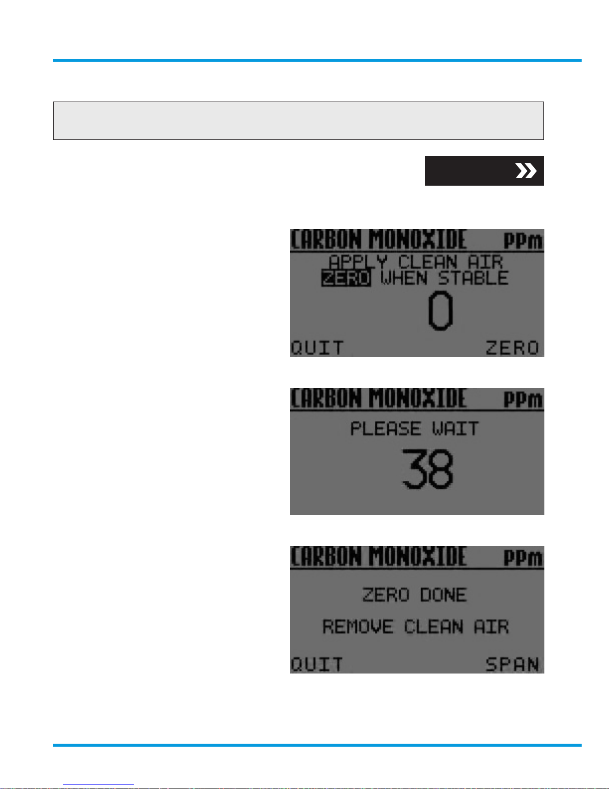
4.4.1 Calibrate
Connect a Gas Test Kit equipped with both ‘clean air’ and the appropriate test
gas canisters.
Calibrate Zero
• Follow the prompt bar
and screen instructions
• Go to Span
Section 5.2
www.trolex.com
Page 36
36 P5536.1600 rev A
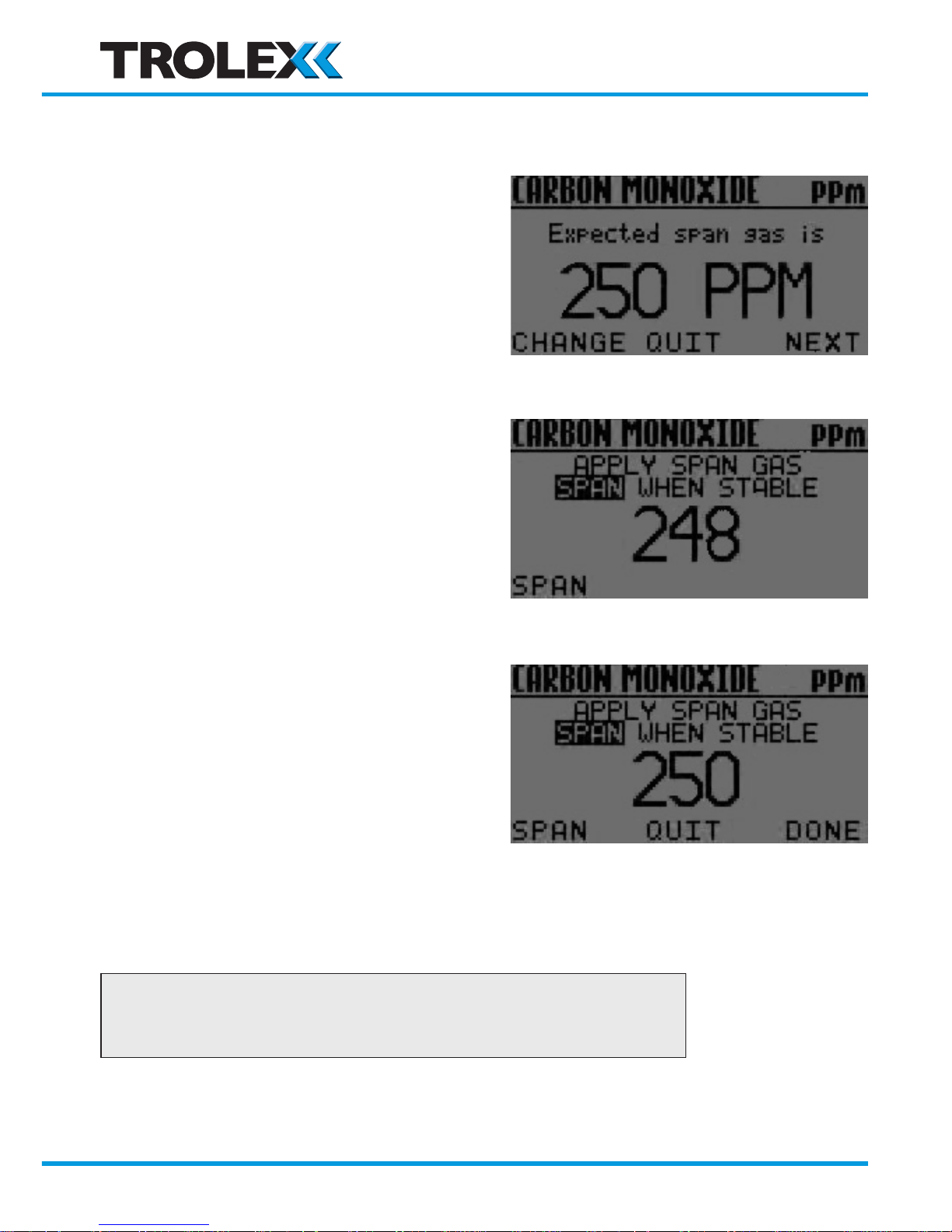
Calibrate Span using a Test Gas of EXPECTED value
• Follow the prompt bar
and screen instructions
• Key Done and return
to the Main Display
Press L and R together to quit and return to the main display.
www.trolex.com
Page 37
TX6351 • TX6352 User Manual
P5536.1600 rev A 37
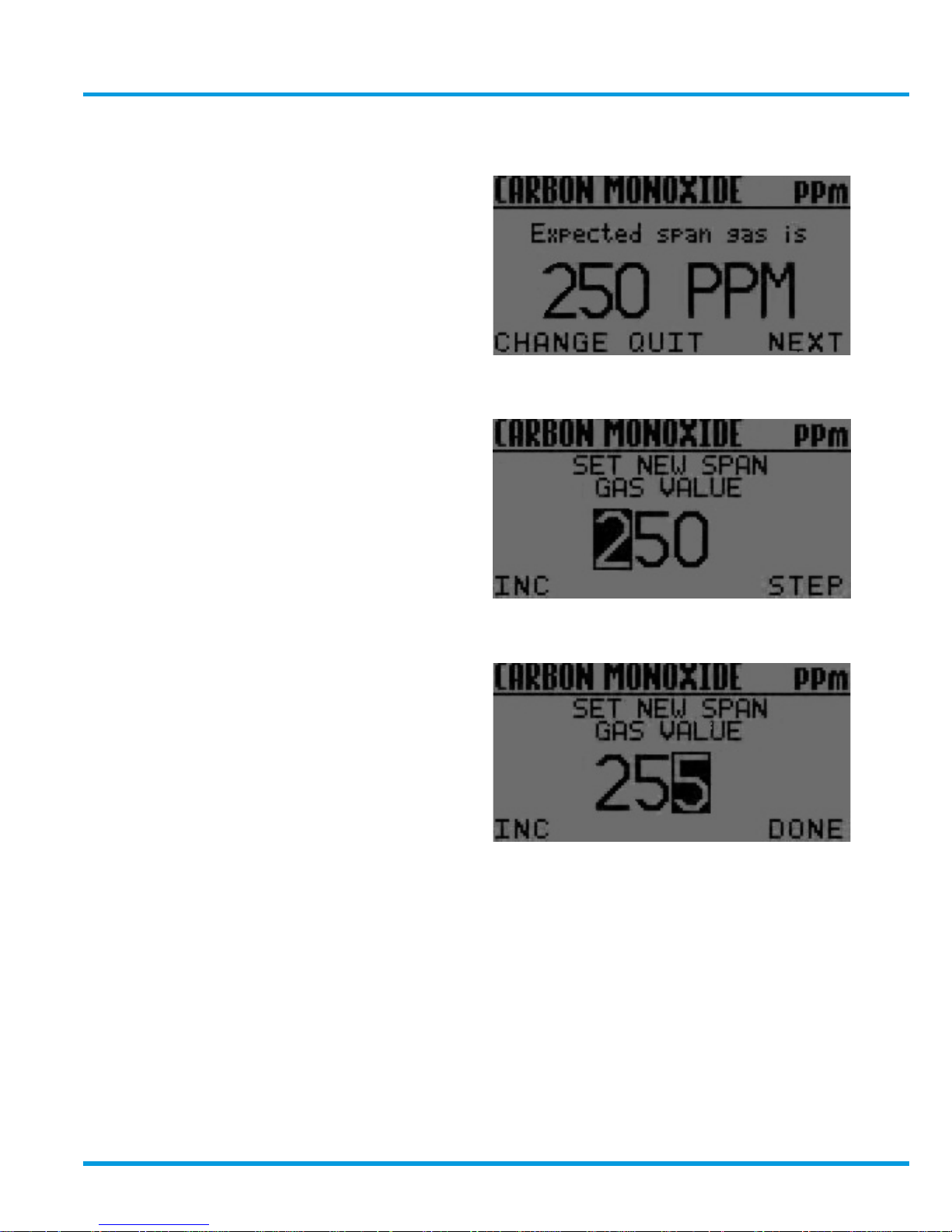
Calibrate Span using a Test Gas of DIFFERENT value
The display will show the concentration
of Span Gas that is EXPECTED to be
used.
Set the expected value to agree with
the actual Test Gas value:
• Follow the prompt bar
and screen instructions
Press R to continue with the
normal span calibration
(previous page)
www.trolex.com
Page 38
38 P5536.1600 rev A
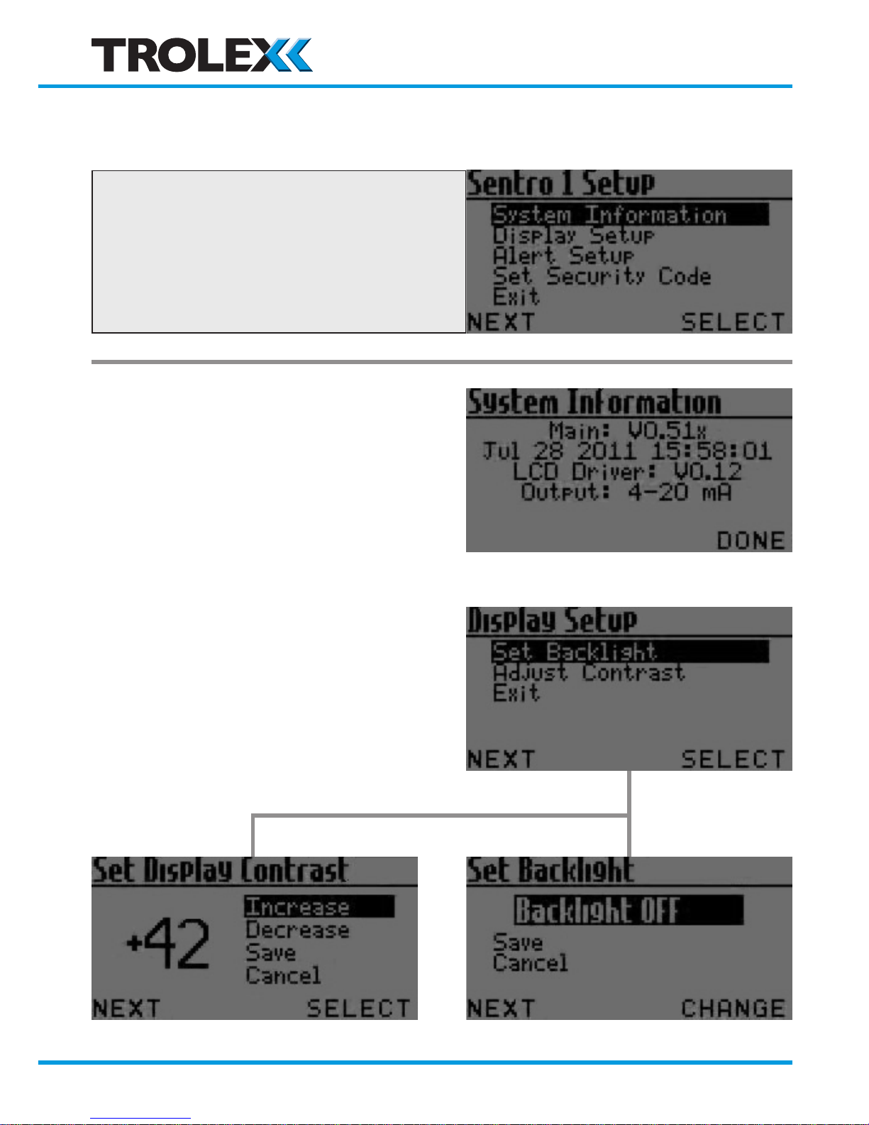
4.4.2 Sentro 1 Setup
The basic functional characteristics of
the sensor can be setup, or reviewed,
from a choice of parameters.
System Information Display
Display Setup
• The display backlight illumination
may be set to on, or off, to reduce
power consumption.
(TX6351 only)
• The contrast of the display
may be set for best
visual appearance.
www.trolex.com
Page 39
TX6351 • TX6352 User Manual
P5536.1600 rev A 39
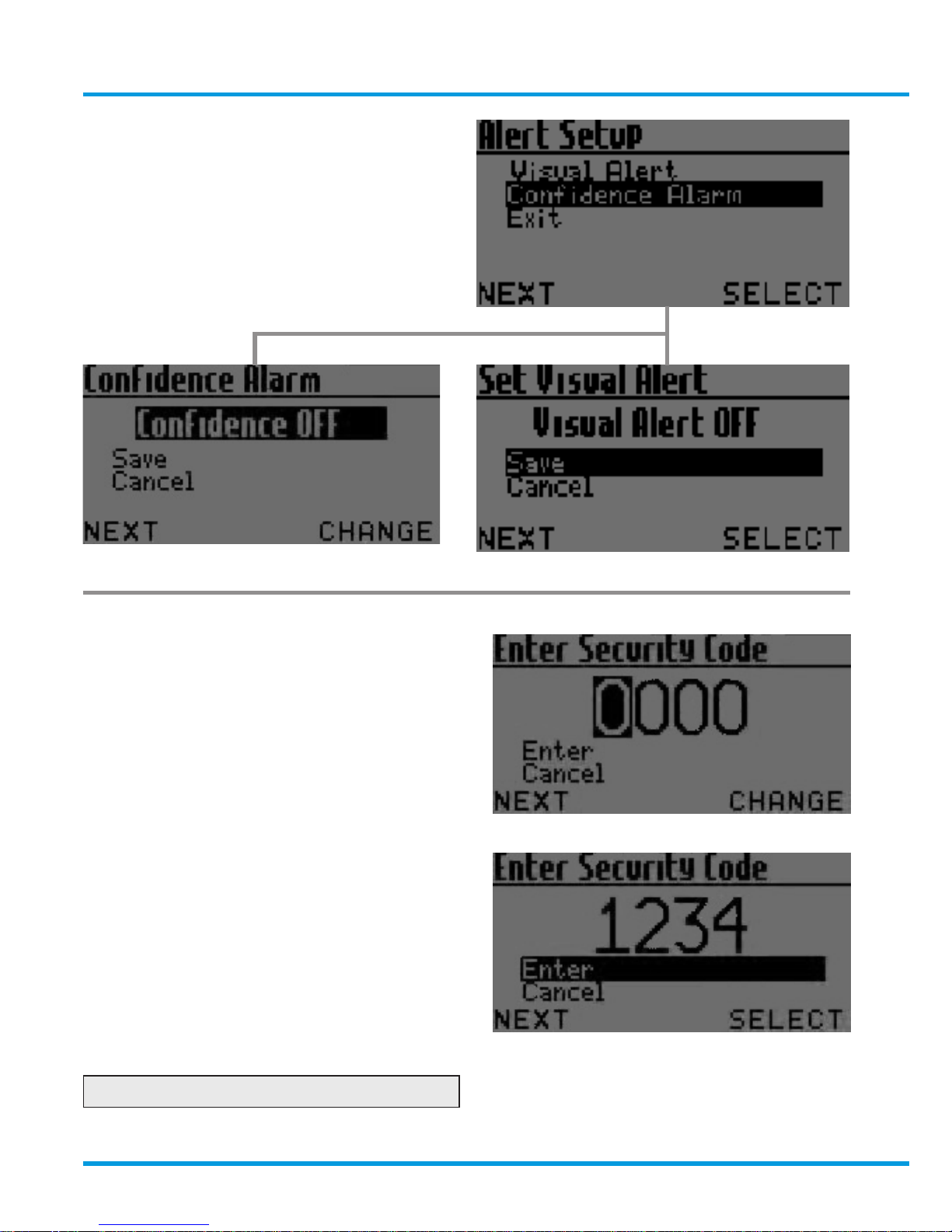
Alert Setup (TX6351 only)
• The integral GENERAL and HIGH
visual alarms can be set to
ON or OFF.
• The ‘confidence’ condition flash
can be set to ON or OFF.
Set Security Code
• A four digit security code can be
entered to prevent unauthorised
access to the setup menu.
0000: Security protection OFF
www.trolex.com
Page 40
40 P5536.1600 rev A
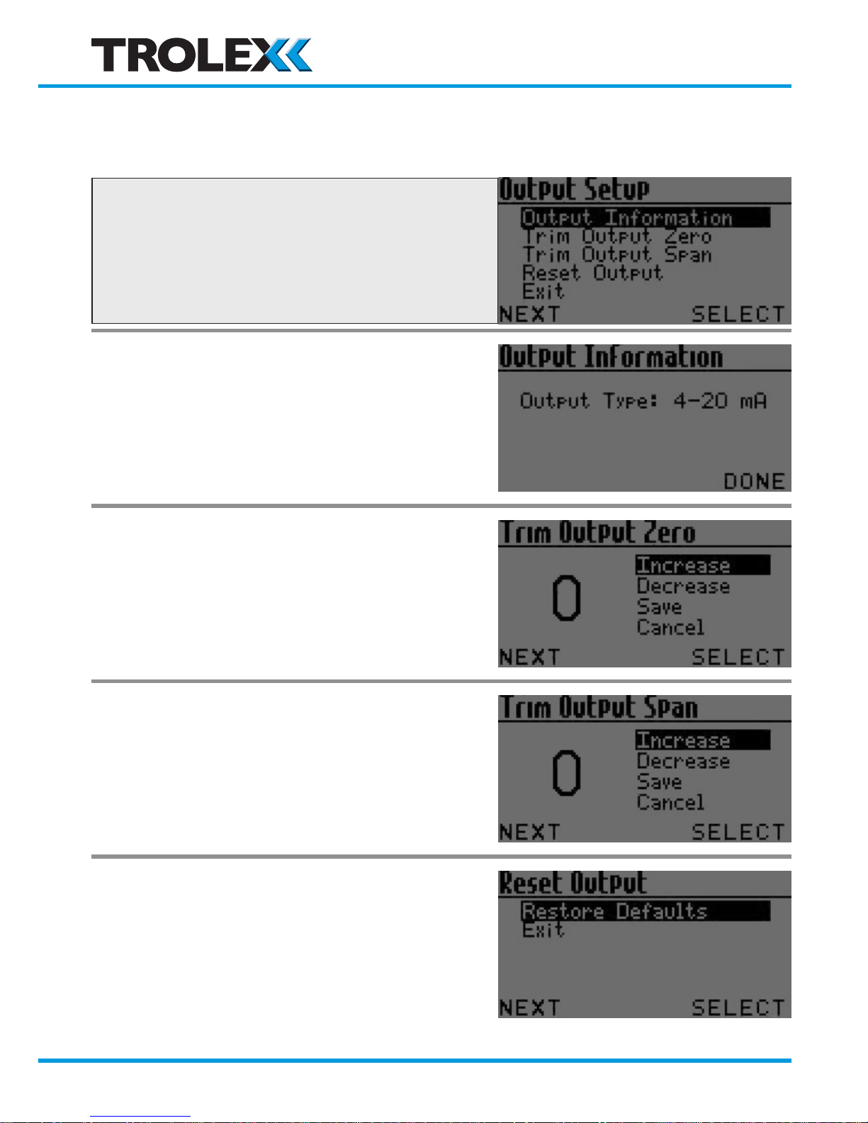
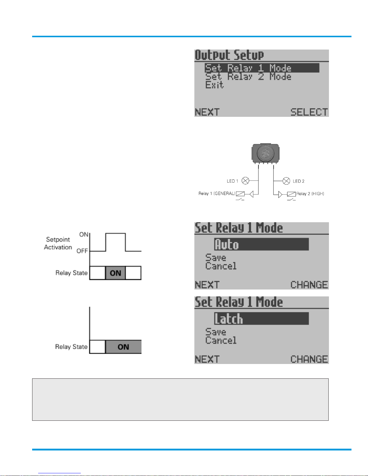
4.4.3 Output Setup
The output signal format can be
reviewed and setup to preferred values.
Output Information
• This is the factory setting of the
output signal
• Confirm acceptance.
Trim Output Zero
• The level of the transmitted output
signal, when the sensor is measuring
a Zero gas concentration can be
trimmed or offset.
Trim Output Span
• The level of the transmitted output
signal when the sensor is measuring
a given Span can be trimmed or offset.
Reset Output
• Reset the Zero and Span output
signal levels to the original
default settings.
www.trolex.com
Page 41
TX6351 • TX6352 User Manual
P5536.1600 rev A 41
Relay 1 Function Mode
Relay 2 Function Mode
• This item will appear in the
menu on the Contact Output
version only.
• The operating function of each
relay can be independently setup.
Checkpoint
The general relay function will be reversed when monitoring oxygen deficiency
(i.e. the relay will de-energise when the measured gas concentration recedes
from the setpoint value).
www.trolex.com
Page 42
42 P5536.1600 rev A
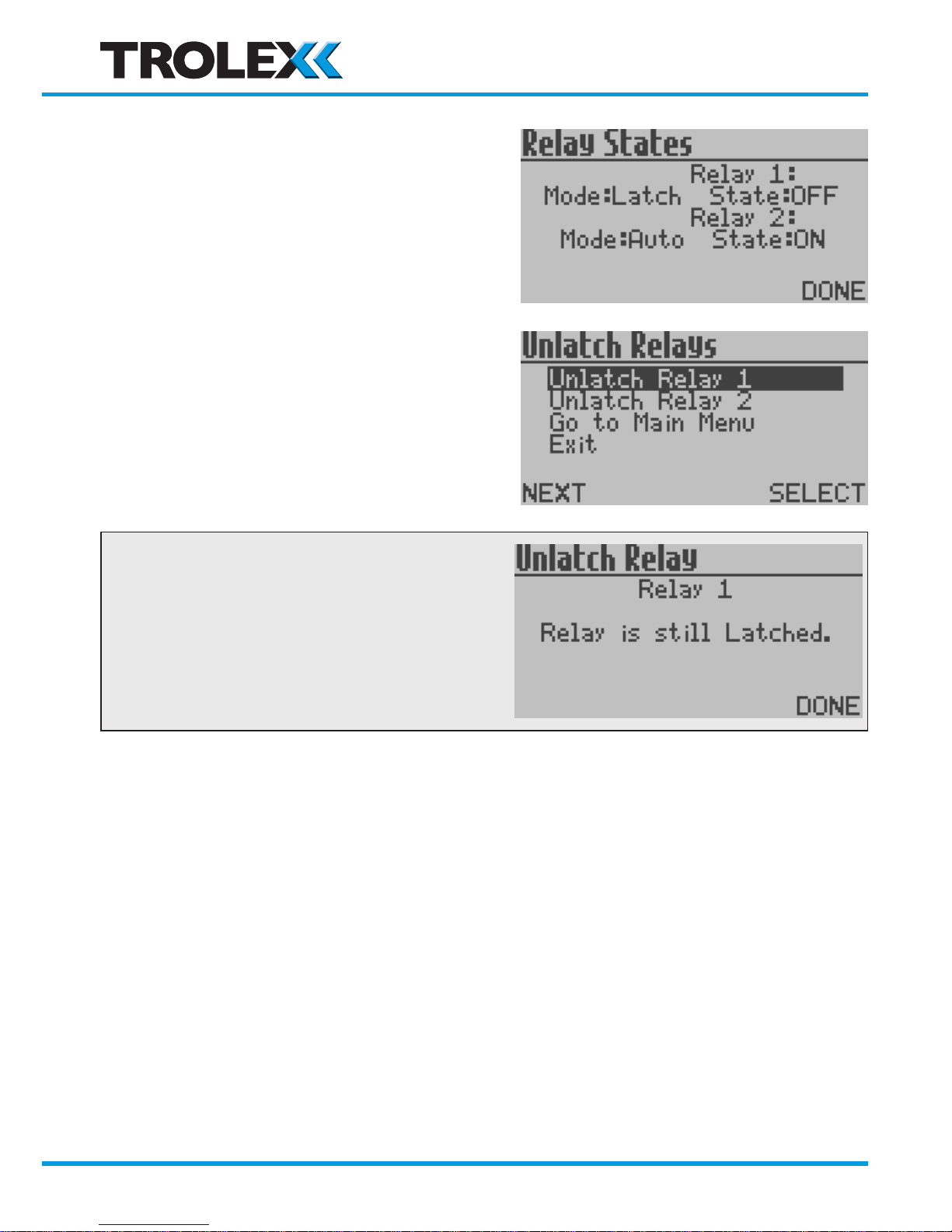
To Reset a Latched Relay
Press L to view Relay Status
Checkpoint
A Relay will stay LATCHED if the initiating
signal has not receded.
www.trolex.com
Page 43
TX6351 • TX6352 User Manual
P5536.1600 rev A 43
4.4.4 Modbus
RS485 Output
• The protocol characteristics required for the Modbus datacomms version
can be setup. Sentro can then be integrated into a wider communication
network or to interface with a PC or SCADA system.
Data Protocol Modbus
Addresses 1 to 255
Format Binary
Databits 8
Stopbits 1
Parity None
Baud Rate
300/600/1200/2400/4800/9600/
14400/19200/28800/38400/57600/115200
TX On 0 to 99 ms
TX Off 0 to 99 ms
Duplex Half
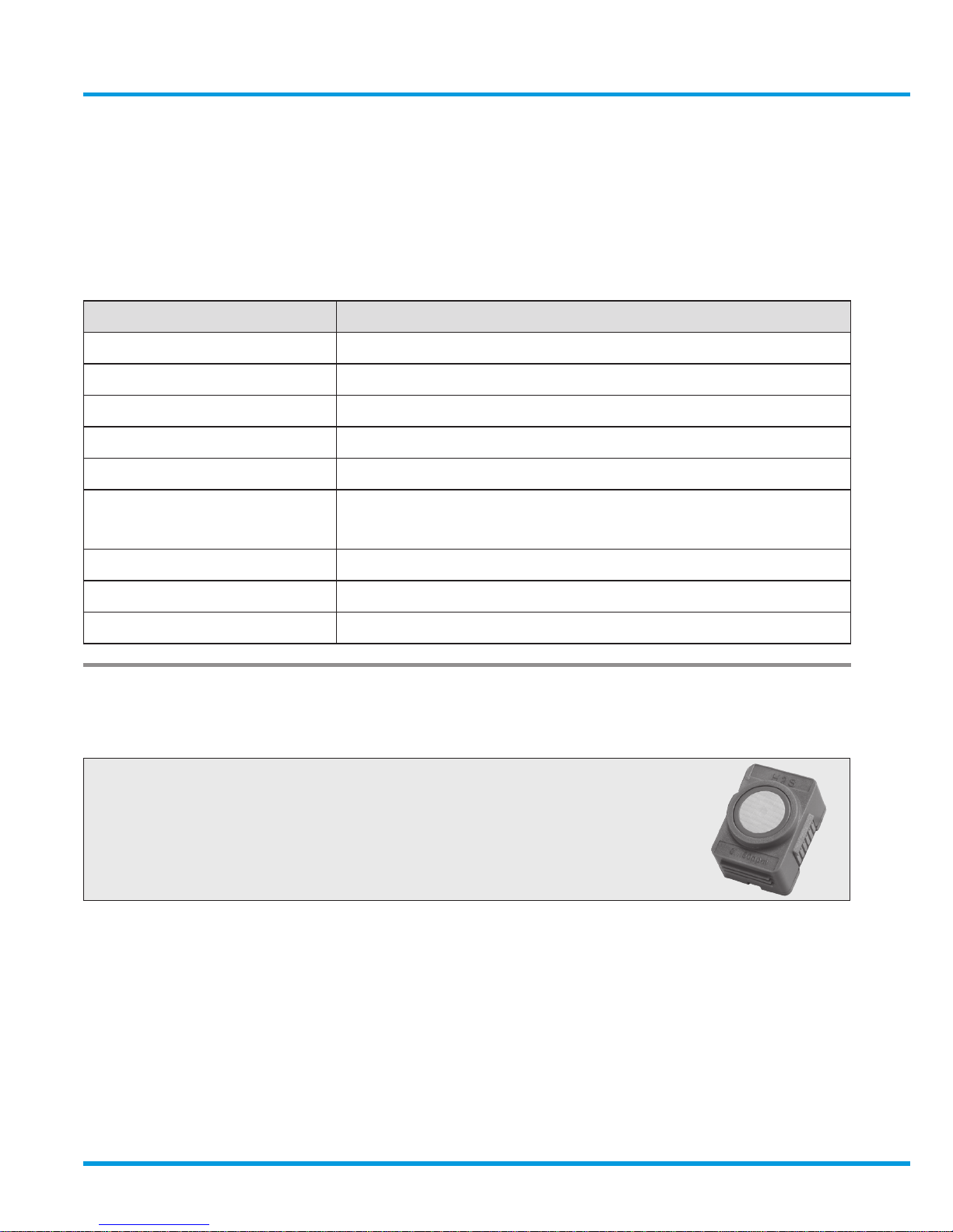
4.4.5 Module Setup
The functional characteristics of the
Sentro eModule may be setup
to preference.
Change Setpoint 1
Change Setpoint 2
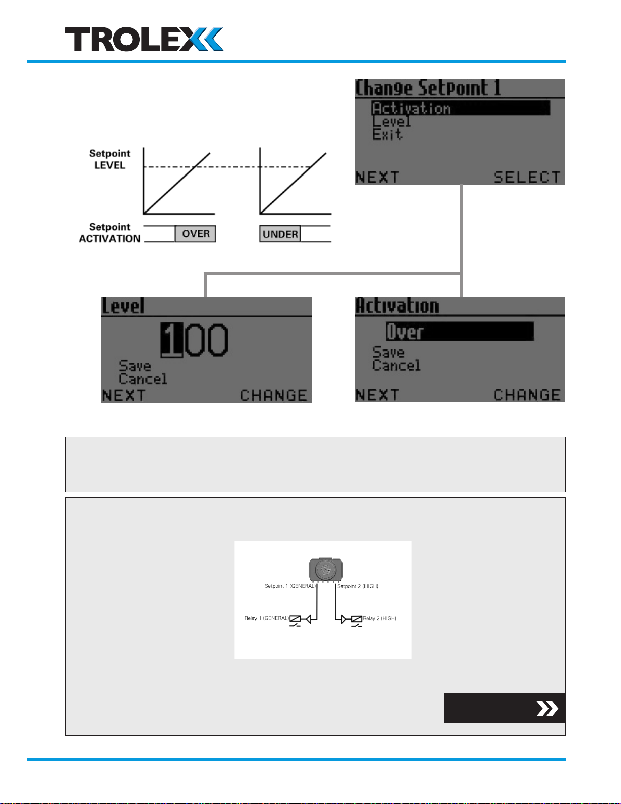
• The Sentro Module provides two adjustable setpoint output signals
• When setpoint 1 (General) is activated, the LED alarm indicators in the
display window flash simultaneously at a rate of about once every two
seconds. When setpoint 2 (high) is activated, they flash simultaneously at a
rate of about 2 per second
www.trolex.com
Page 44
44 P5536.1600 rev A
• The Activation mode and operating
level of the setpoints can be setup
to preference.
Checkpoint
• The setpoint output signal data will also be available for transmission
on the RS485 Modbus version of Sentro.
Checkpoint
• The Contact Output version of Sentro 1 is also equipped with two relays
• The Activation will operate in the same way
• The Relay Function mode can also be setup
Section 4.4.3
www.trolex.com
Page 45
TX6351 • TX6352 User Manual
P5536.1600 rev A 45
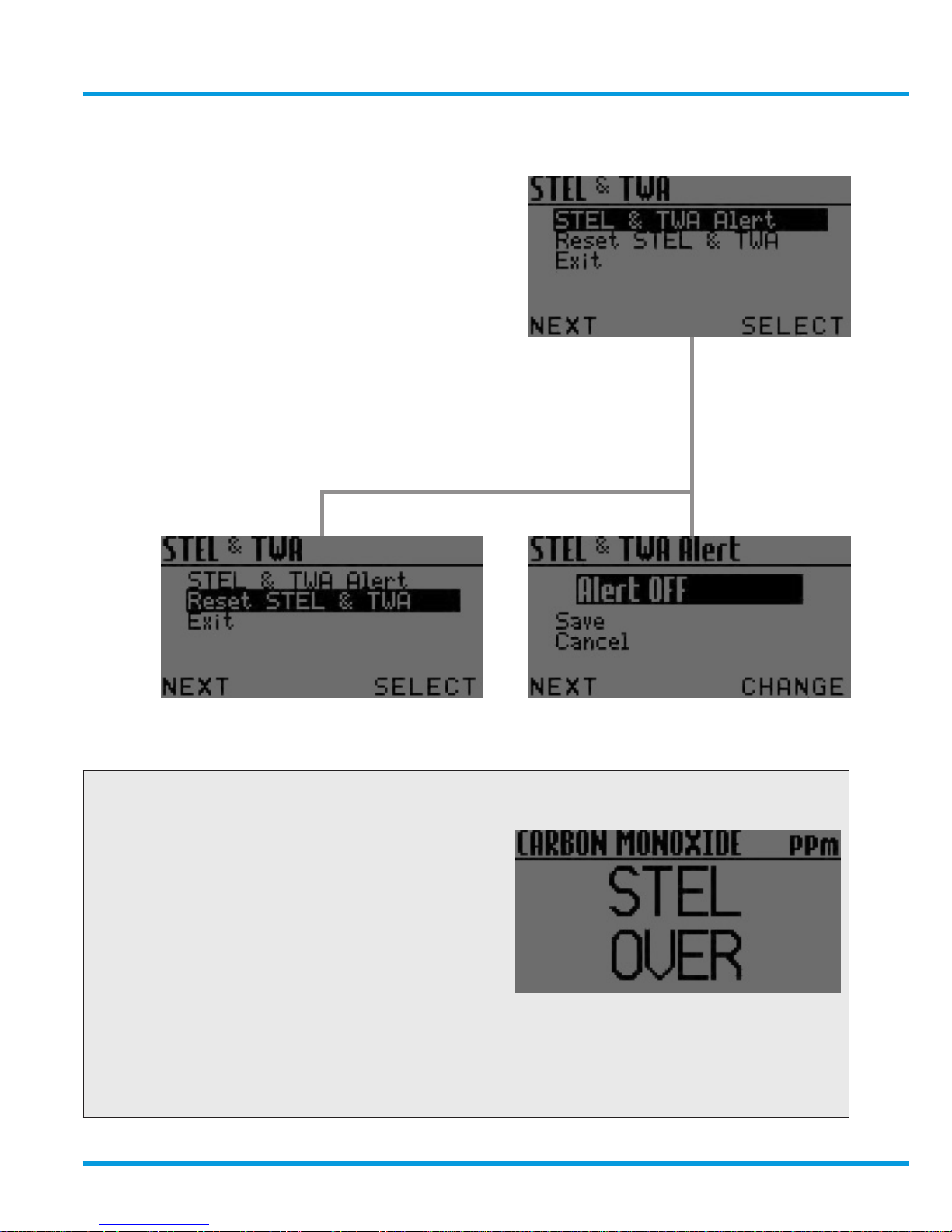
STEL and TWA
• Toxic gas sensing Sentro eModules
are equipped to automatically calculate
STEL and TWA limits in accordance
with international EH40
recommendations
• The Alert can be set to ON or OFF
• The accumulated STEL and TWA data
can be reset to zero ready for the start
of a new working period.
Checkpoint
• STEL OVER or TWA OVER will
be displayed when limits are
exceeded.
• If the visual alarm has been enabled
then this will also activate at
level 1 when a STEL or TWA limit
is exceeded.
• For a contact output version, the STEL and TWA alert will also initiate
the Activate command for Relay 1.
www.trolex.com
Page 46

46 P5536.1600 rev A
4.4.6 Support
If you need technical support to operate this product, or would like details of our
after sales technical support packages, contact [email protected].
www.trolex.com
Page 47
TX6351 • TX6352 User Manual
P5536.1600 rev A 47
5. Diagnostics and Maintenance
5.1 Diagnostic Messages
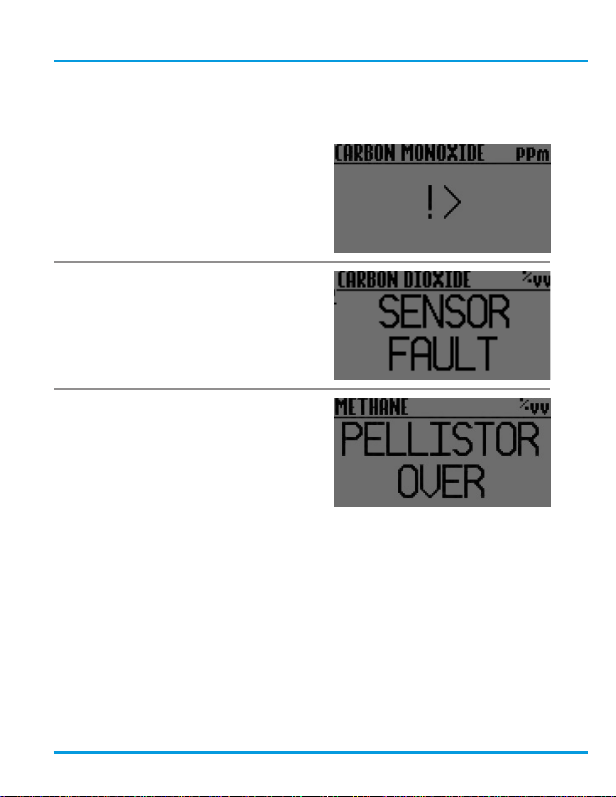
Sensor over-range
Loss of signal from the sensor
Pellistor Over
• The gas sensing concentration
exceeds 100% LEL which is the
safe working limit of the sensing
element.
• The transmitted output signal from the sensor will be clamped at full
scale to prevent ambiguous output data from being transmitted and
will latch in this condition
• The pellistor in the gas sensing module will be switched into a
PROTECT state to prevent oxidisation damage and will latch in this state.
• Check that the gas concentration has receded, then reset the module
by removing it for 2 seconds.
www.trolex.com
Page 48
48 P5536.1600 rev A
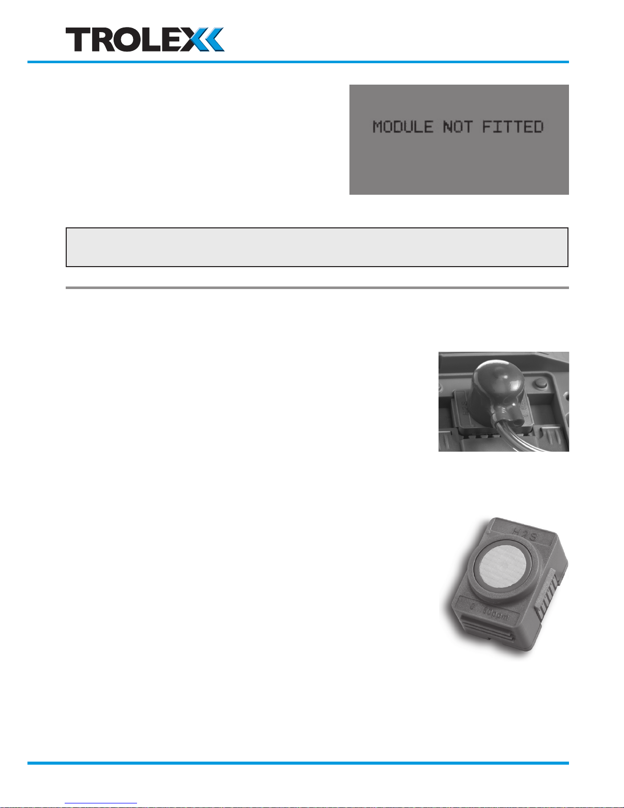
Module Not Fitted
• The eModule has been removed
and is out for more than 10 seconds
Checkpoint
• Under-range output signal will be transmitted by the sensor.
5.2 Maintenance
Output Signal
• Check the accuracy of the sensor at
pre-determined intervals by injecting
a test gas
Gas Sensing Modules
• The Sentro eModules should be
changed at regular intervals to ensure
the accuracy of response
• Service history is logged within the
module and this data is used to
periodically assess its condition whenever
it is returned for servicing. Simply insert
the new module into the instrument and
return the original for checking and
calibration.
www.trolex.com
Page 49
TX6351 • TX6352 User Manual
P5536.1600 rev A 49
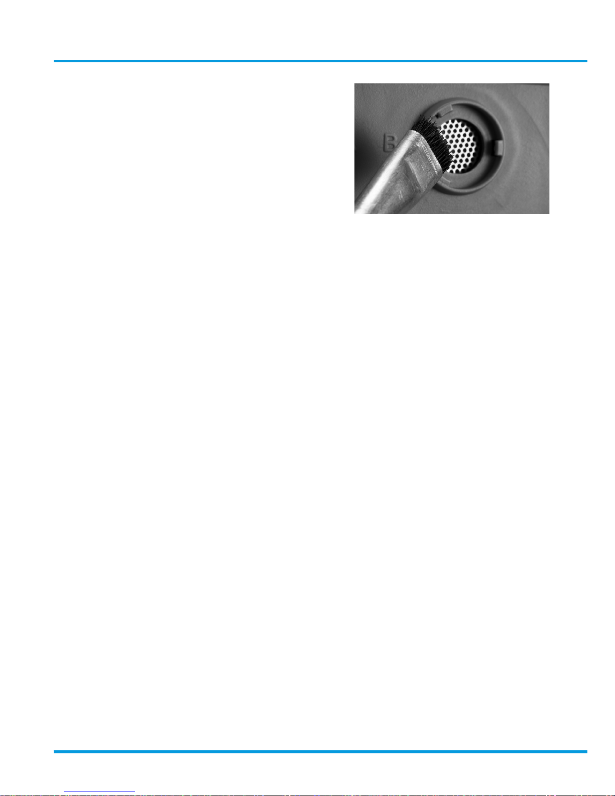
Gas Inlet Port
• Check the condition and clean with a
small brush to remove dust and debris
Annual Safety Check
The main sensor unit will not normally require maintenance or calibration, but it is
advisable to return it to the Trolex Product Support Department for an annual safety
check.
Calibration
The Sentro 1 performs an important safety function and periodic calibration is an
essential part of maintaining safety integrity.
Gas sensors have a known ZERO and SPAN movement related to time, level of
exposure to gas, and the nature of the environment, so Trolex recommend that the
sensors should be bump tested with a suitable test gas at regular intervals. This
should be carried out in accordance with best practice for the industry where the
gas sensor is being used.
Periodic calibration of the gas sensor should be carried out whilst it is in service. For
oxygen and carbon monoxide gas sensors Trolex recommends that this is carried
out every 3 weeks. For other gas sensors Trolex recommends that this is carried
out in accordance with best practice for the industry where the gas sensor is being
used, and should take into consideration local operating conditions.
www.trolex.com
Page 50
50 P5536.1600 rev A
Recommended Test Gas Concentration
Gas Sensor Type Zero Gas Calibration Gas/ balance gas
CH4 (Pellistor) 100% LEL Zero Air 2.2% v/v CH4 in air
CH4 (Infra Red) Zero Air or Nitrogen 100% 50% to 100% of range CH4 in N
2
CO Zero Air 50% to 100% of range CO in air
H2S Zero Air 50% to 100% of range H2S in air
NO Zero Air 50% to 100% of range NO in air
NO
2
Zero Air 50% to 100% of range NO2 in air
SO
2
Zero Air 50% to 100% of range SO2 in air
CO
2
Nitrogen 100% 50% to 100% of range CO2 in air
O
2
Nitrogen 100%
Clean air, or 50% to 100% of
range O2 in N
2
Standard test gas canisters are available from our Product Support department and
can be supplied in a range of capacities from 34 litres up to 110 litres.
Please call our sales engineers for advice regarding recommended test gas
procedures and product support plans.
Checkpoint
• CH4 test gas must be combined with balance air if being used to calibrate
pellistor based devices.
• 25% O2 cannot be shipped by air transport, so a concentration below 23%
would be supplied.
www.trolex.com
Page 51
TX6351 • TX6352 User Manual
P5536.1600 rev A 51
5.3 Maintenance and Calibration Log
Order Reference: TX
Serial Number: Date Purchased:
Gas Type: Location:
Date
Scheduled
Check
Fault Recalibrate
Change
Modules
Return
to Trolex
Comments
www.trolex.com
Page 52

52 P5536.1600 rev A
5.4 Disposal
Part of the ethos of Trolex is sustainable design. Sentro 1 contains materials that
can be recovered, recycled and reused. At the end of its useful life ensure that the
Sentro 1 is recycled in accordance with local laws and bylaws for the geographic
area where it is located. The end of its useful life is to be determined by the owner/
operator of the equipment and not Trolex. Ensure that the Sentro 1 is recycled by
licenced waste contractors with the appropriate licences for handling electronic
waste in the geographic area where the Sentro 1 is located.
Checkpoint
Consult your local Trolex service agent or the Trolex Product Support Department
if you require assistance with disposal: [email protected]
www.trolex.com
Page 53

TX6351 • TX6352 User Manual
P5536.1600 rev A 53
Disclaimers
The information provided in this document contains general descriptions and
technical characteristics of the performance of the product. It is not intended as
a substitute for and is not to be used for determining suitability or reliability of
this product for specific user applications. It is the duty of any user or installer to
perform the appropriate and complete risk analysis, evaluation and testing of the
products with respect to the relevant specific application or use. Trolex shall not be
responsible or liable for misuse of the information contained herein. If you have any
suggestions for improvements or amendments, or find errors in this publication,
please notify us at [email protected].
No part of this document may be reproduced in any form or by any means,
electronic or mechanical, including photocopying, without express written
permission of Trolex.
All pertinent state, regional, and local safety regulations must be observed
when installing and using this product. For reasons of safety and to help ensure
compliance with documented system data, only Trolex or its affiliates should
perform repairs to components.
When devices are used for applications with technical safety requirements, the
relevant instructions must be followed.
Trademarks
© 2015 Trolex® Limited.
Trolex is a registered trademark of Trolex Limited. The use of all trademarks in this
document is acknowledged.
Document History
Revision Date ECN
08 20 -11- 2014 N/A
09 20 - 01- 2015 N/A
A 11 - 12- 2015 4262
B 25 - 04 -2016 4483
P5536.1600 rev A 02- 05 -2018 N/A
www.trolex.com
Page 54

Contact Details
Trolex Ltd, Newby Road, Hazel Grove, Stockport, Cheshire, SK7 5DY, UK
+44 (0) 161 483 1435 [email protected]
Page 55

Page 56

Page 57

Page 58

 Loading...