

Page 1
Page 2

Page 3

TX3706-UM-EN-02 3
TX3706 • User Manual
TX3706 • FALCON 25 Series Ex Connectors
Contents
1. Product Overview 4
1.1 Operating Features 4
1.2 Application 5
1.3 Dimensions 5
1.4 Technical Data 6
1.5 Contact Inserts 7
2. Certification & Conformity 8
3. Fitting and Installation 10
3.1 Precautions 10
3.2 Tools and Equipment 11
3.3 Free Plug and Free Receptacle 11
3.3.1 General assembly & definitions 11
3.3.2 Connecting 12
3.3.3 Earth bonding 14
3.3.4 Security coding 14
3.4 Fixed Receptacle 15
3.4.1 General assembly & definitions 15
3.4.2 Bush mounting 16
4. Operation 17
4.1 Engage and separate 17
4.2 Safety precautions 18
4.2.1 Isolate elsewhere 18
4.2.2 Pilot circuit interlocking 19
4.2.3 Live engagement 20
5. Accessories 22
6. Maintenance 23
Disclaimers 23
Trademarks 23
Contact Details 23
www.trolex.com
Page 4
4 TX3706-UM-EN-02
1. Product Overview
1.1 Operating Features
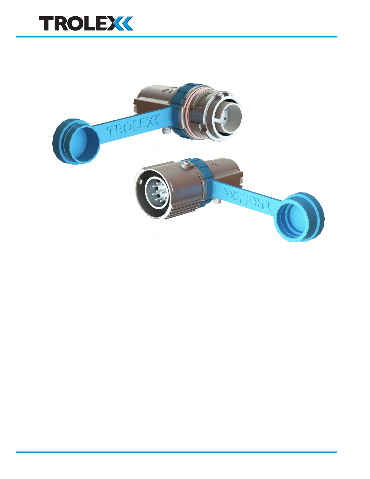
• Multi-pin connector for use in Group I and Group II hazardous areas
• Precision cast metal Line Plug and Line Receptacle for cable mounting
• Precision cast metal Fixed Receptacle for Ex d or Ex e box mounting
• Standard cable glands are utilised to user preference
• Simple connection - no special tools required
• Double insulated contact cartridge for added safety and ease of connection
• Rapid double bayonet engagement ensures that contacts make or break under Ex d
protection for live disconnection
• Pilot circuit interlocking safety protection can be incorporated
• Security coding options to prevent non-permitted engagement
• Supplied with flexible ingress protection cover caps
• Ex d blanking cover caps may be supplied where specified
• Mounting clamp available for Unistrut bulkhead mounting of Free Connectors
www.trolex.com
Page 5
TX3706 • User Manual
TX3706-UM-EN-02 5
1.2 Application
• High integrity, multi path, robust, explosion proof connector, designed for extra heavy
duty and critical applications.
• ATEX and IECEx industrial hazardous area applications and underground mines. Suitable
for use in flammable gas and dust atmospheres.
• Rapid and convenient connect/disconnect of control circuits and power circuits for
electrical equipment installation.
• Live disconnect of critical equipment for maintenance and change-out.
• Offshore oil and gas platforms, mining, tunnelling, petrochemical plants, process plants,
storage areas, pump stations, well head control panels, mobile equipment, on shore drill
rigs and top drive control room systems.
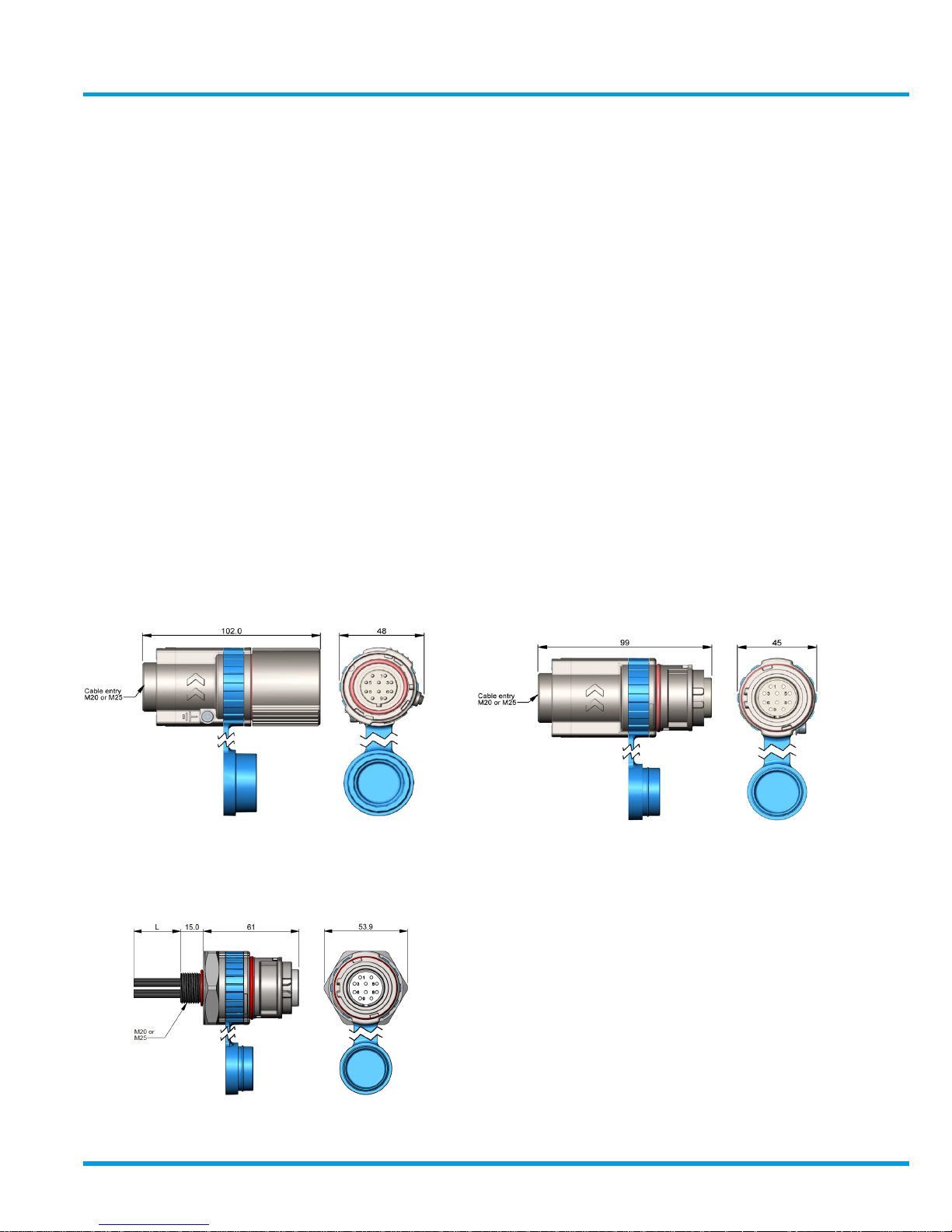
1.3 Dimensions
TX3706.1 Line Plug
TX3706.3 Fixed Receptacle
M20 or M25 bush mounting on
Ex d or Ex e enclosures
TX3706.2 Line Receptacle
www.trolex.com
Page 6

6 TX3706-UM-EN-02
1.4 Technical Information
Housing material: Stainless Steel : ANC4B
Aluminium Alloy : LM25TF with hard anodised protection
Cable entry on free
plug and receptacle:
Choice of threaded cable entry sizes for standard Ex d cable glands
M20 and M25
Mounting of fixed
receptacle:
• M20 onto Ex d or Ex e housing
• M25 onto Ex d or Ex e housing
Connections of fixed
receptacle:
1.5 mm2 x 1m / 2m / 3m (L)
2.5 mm2 x 1m / 2m / 3m (L)
Mating cycles: 100,000 with no load connected
(Limited to 200 for live disconnect)
Security Coding: 5 selectable coding positions - A, B, C, D, E
Ingress protection: IP66
Temperature limits: -50 °C to +60 °C
Weight:
Free Plug
Free Receptacle
Fixed Receptacle
Stainless Steel Aluminium
0.5kg 0.2kg
0.43kg 0.17kg
0.4kg 0.15kg
Conformity: EN 61984: 2009 - Safety Requirements
EN 60664: 2007 - Insulation Co-ordination
EN60079-0: 2012+A11:2013 - General Requirements
EN60079-1: 2014 - Flame-proof Enclosures
EN60079-7: 2015 -Explosive atmospheres. Equipment protection by
increased safety “e”
EN60079-31: 2014 - Equipment Dust Ignition Protection
by Enclosure “t”
www.trolex.com
Page 7
TX3706-UM-EN-02 7
TX3706 • User Manual
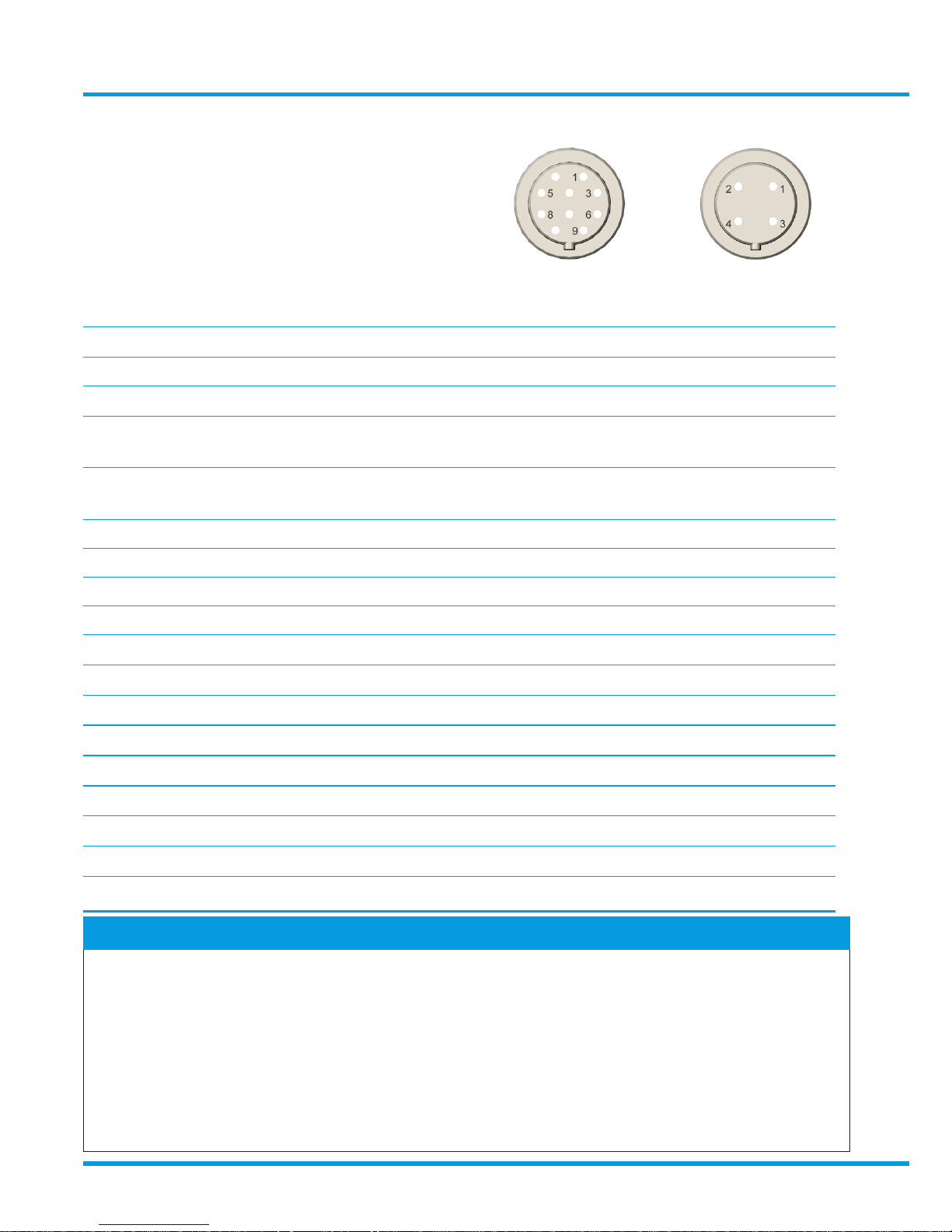
Contact Inserts
Contact ways: 10 4
Maximum rated current per contact: 25 A 25 A
Maximum total current (all contacts): 100 A 100 A
Rated voltage: 250 V ac/ 100 V dc 250 V ac/ 100 V dc
Maximum live disconnect voltage
Power factor 0.4 to 0.5
80 V ac/dc 250 V ac/dc
Load breaking current
(up to 200 mating cycles):
1 A 1 A
Creepage and clearance: (IEC 60664-1) 2 mm 5 mm
Cable terminations: 6 or 8 point crimp or solder - IEC 60352-2
Wire size: 1.5 mm2 or 2.5 mm
2
Insert material: Glass filled polymer
Fire rating: VL94, V-0
Contacts: Multi-spring wire socket and solid pin
Insertion force: 6 N per contact
Contact protection: Passivated silver plating
Contact resistance: 400 ohm
Test Voltage: 2000 V
Insulation: Class II double insulated BS 61140
Over voltage transients: 3000 V
Protective earth connections Screw clamp terminals for 2.5 mm cables
Checkpoint
Intrinsically safe circuits
The contact inserts are clearance compatible for use with approved intrinsically safe
circuits up to 30 Volts. This feature can be used to maintain flameproof properties where
intrinsically safe circuits are exiting a flameproof enclosure.
Caution
Intrinsically safe circuits must not be mixed with non-intrinsically safe circuits on the same
connector.
www.trolex.com
Page 8
8 TX3706-UM-EN-02
2. Certification and Conformity
ATEX (European Union) certification for use in underground mines and surface
industry with explosive gas and dust atmospheres.
Complies with ATEX Directive 2014/34/EU
IECEx (International) certification for use in underground mines and surface industry
with explosive gas and dust atmospheres.
2.1 Underground mines (stainless steel versions only)
1) Line Plug and Line Receptacle
Product Code: Ex Certificate Number: Ex Certification Code:
TX3706.1.19.01.xx.xx.xx.xx
TX3706.2.19.01.xx.xx.xx.xx
TX3706.4.19.01
CML 15ATEX1143X
IECEx CML 15.0070X
I M2
Ex db I Mb
-50 °C ≤ Ta ≤ +60 °C
2) Fixed Receptacle (low risk of mechanical danger only-refer to conditions of use below)
Product Code: Ex Certificate Number: Ex Certification Code:
TX3706.3.19.01.xx.xx.xx.xx.xx CML 15ATEX1143X
IECEx CML 15.0070X
I M2
Ex db I Mb
Ex db eb I Mb
-50 °C ≤ Ta ≤ +60 °C
2.2 Surface industry with explosive gas and dust atmospheres
(stainless steel and aluminium versions)
1) Line Plug and Line Receptacle
Product Code: Ex Certificate Number: Ex Certification Code:
TX3706.1.20.xx.xx.xx.xx.xx
TX3706.2.20.xx.xx.xx.xx.xx
TX3706.4.20.xx
CML 15ATEX1143X
IECEx CML 15.0070X
II 2GD
Ex db IIC T4 Gb
Ex tb IIIC T135 °C Db
-50 °C ≤ Ta ≤ +60 °C
www.trolex.com
Page 9

TX3706-UM-EN-02 9
TX3706 • User Manual
2) Fixed Receptacle
Product Code: Ex Certificate Number: Ex Certification Code:
TX3706.3.20.xx.xx.xx.xx.xx.xx CML 15ATEX1143X
IECEx CML 15.0070X
II 2GD
Ex db IIC T4 Gb
Ex db eb IIC T4 Gb
Ex tb IIIC T135 °C Db
-50 °C ≤ Ta ≤ +60 °C
2.3 The following Conditions of Certification and Special
Conditions for Safe Use apply to the above ATEX and IECEx
Certificates:
The following conditions relate to safe installation and/or use of the equipment:
1) When included, the total capacity of all pin options shall not exceed 100 A, with a maximum
rating per pin of 25 A.
2) The cable entries and cable used with the TX3706 Falcon 25 Connectors may reach 60°C
above ambient temperatures, therefore, shall be selected accordingly for these temperatures.
3) The connector arrangement remains flameproof through the first stage of disconnection
which fully disconnects the pins, however, this only applies to circuits with a power factor of
between 0.6 and 1.0. For circuits outside this range, unless for resistive loads only, additional
time delays shall be considered before fully disconnecting the connector even if de-energised.
4) The stainless steel fixed receptacle, when used in Group I areas, shall only be used in areas
considered to be low risk of mechanical danger or shall be additionally protected from heavy
mechanical impact by installation.
Under certain extreme circumstances, the non-metallic parts of the clamp may store
electrostatic charge and therefore the user/installer shall implement precautions to prevent
the build-up of electrostatic charge, e.g. locate the clamps where a charge-generating
mechanism (such as wind- blown dust) is unlikely to be present. In addition, the clamp shall
only be cleaned with a damp cloth.
www.trolex.com
Page 10

10 TX3706-UM-EN-02
3. Fitting and Installation
3.1 Precautions
• Special conditions of use relating to the Ex
certification may apply to particular applications.
• The cable gland used with Free Plugs and Free
Receptacles must be an approved Ex d type
which is suitably certified for the equipment and
the type of cable to be used.
• Gland entries must be fitted with suitable ingress
seals to maintain the overall ingress protection of
the connector.
• Ensure that the current and voltage parameters
of the electrical circuits are within the limits
specified.
• The sealing faces and flame paths will have
been treated with a protective film of grease
during manufacture. Renew if necessary before
assembly or engagement, in accordance with the
relevant installation standards and procedures.
• Ensure that the end cap screws are in place and
are fully tightened before engagement.
• Always fit either a rubber ingress protection cap
or an Ex protection cap to disengaged connectors
to protect flame paths and to exclude debris and
moisture.
• Do not disengage the connector by pulling on the
cable as this may damage the fitting of the cable
into the cable gland.
• A connector with a damaged flame path is an
explosion risk and should be removed from
service.
www.trolex.com
Page 11
TX3706-UM-EN -02 11
TX3706 • User Manual
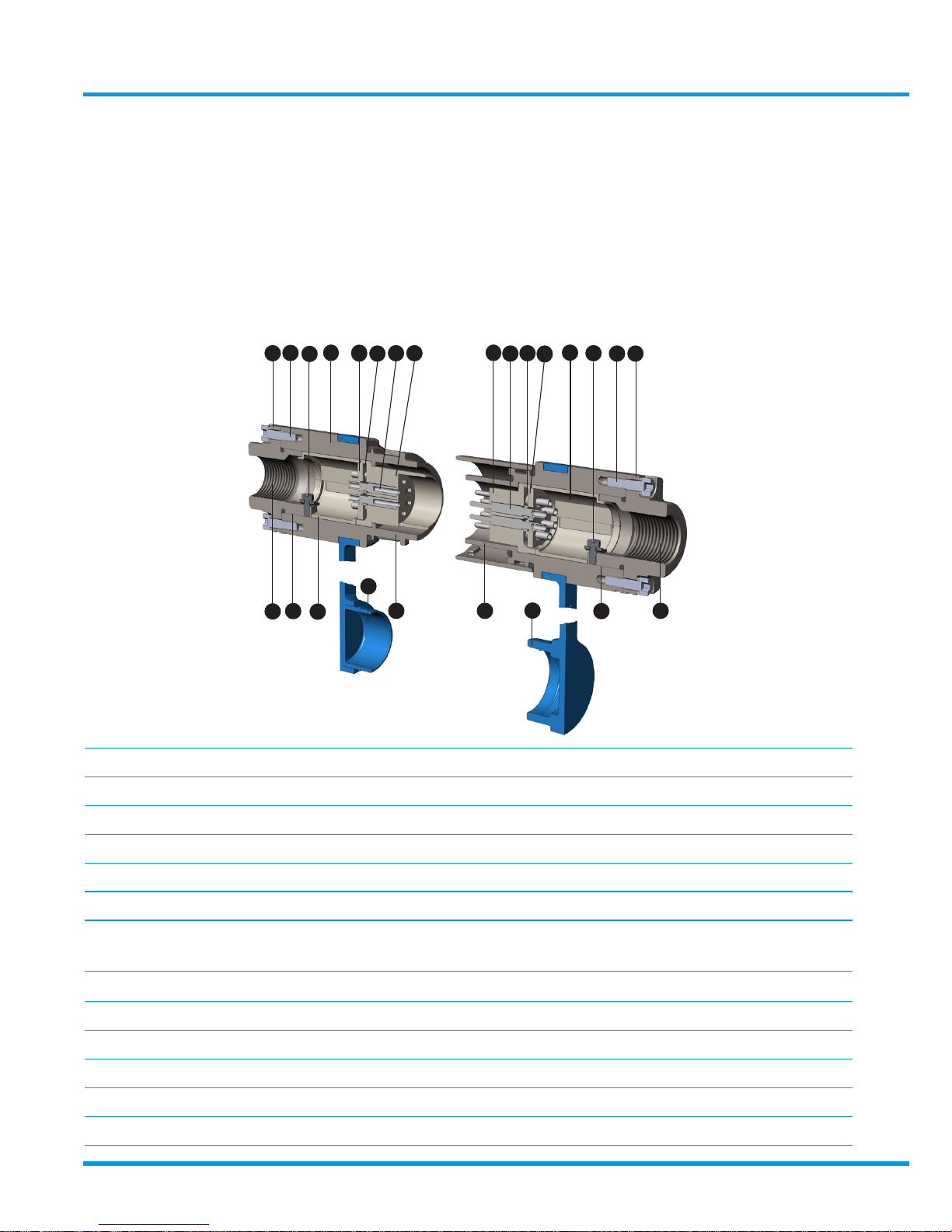
3.2 Tools and Equipment
• 2.5mm & 3mm Allen key
• Wire cutters
Product Options
1. Body (Plug or receptacle) Group I Stainless Steel
1. Body (Plug or receptacle) Group II Stainless Steel/Aluminium
2. End cap
3. End cap screws
4. Contact insert 10 way/4 way
5. Backing ring
6. Contacts 1.5 mm2 Pins/Sockets
2.5 mm2 Pins/Sockets
7. Retainer
8. Sleeve (Upper and lower pair)
9. Ingress protection cap
10. Earth bonding terminal
11. Flame path
12. Cable entry for standard Ex cable glands
M20/M25
• Wire strippers
• 6 or 8 point crimping tool
(or soldering iron for soldered connections)
3.3 Free plug and free receptacle
3.3.1 General assembly and definitions
1
2
3
5
7
6 4
4
6
7
5
8
10
3 2
12
11
9
11
11
9
11
12
10
8
www.trolex.com
Page 12
12 TX3706-UM-EN-02
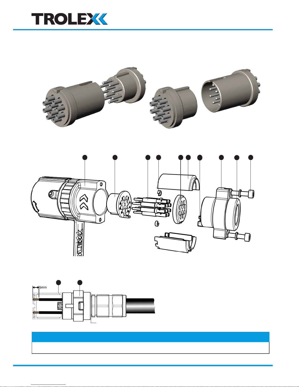
3.3.2 Connecting
• Prepare cable
• PINS or SOCKETS can be fitted into MALE or FEMALE contact inserts
• MALE or FEMALE contact inserts can be fitted into PLUGS or RECEPTACLES
Checkpoint
Use sleeve 8 as a temporary wire length cutting gauge.
1 4 6 7 5 8
10
2
12
3
8 2
Standard Ex cable gland and approved cable (Not supplied)
Ingress protection seal (Not supplied)
www.trolex.com
Page 13
TX3706 • User Manual
TX3706-UM-EN-02 13
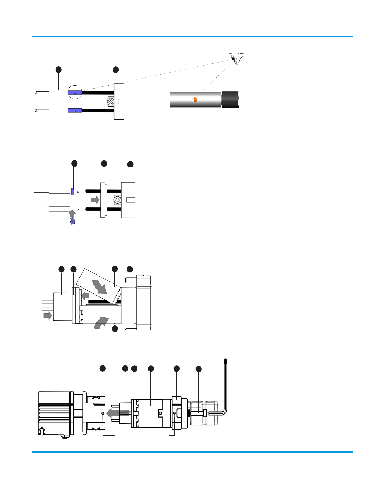
• Crimp or solder connectors
• Fit backing ring 5
• Clip a retaining clip 7 to each contact
• Load contacts into the contact insert 4
• Slide the backing ring 5 up to the contact insert 4
• Clip the sleeves 8 in place
• Load into connector body 1
• Fit end cap screws and washers
5 4
8
2
8
Align markers
6 2
7 5
2
1 4
5 8 2
3
www.trolex.com
Page 14
Code C
14 TX3706-UM-EN-02
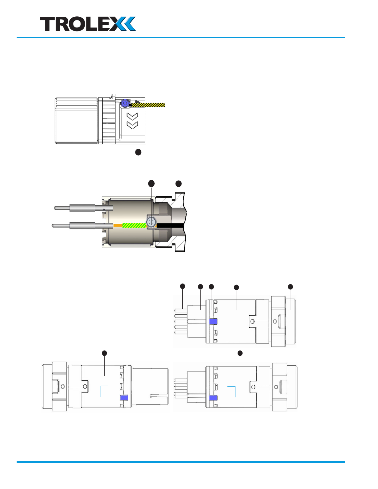
3.3.3 Earth Bonding
• External Earth bonding
• Internal Earth Continuity bonding
3.3.4 Security Coding
Female
Male
< 2.5mm
2
1
10
2
Leading Earth Pin
TX 3706.031. 15
TX 3706.031. 25
6
4 5
8
2
E
D
C
B
A
8 8
E
D
C
B
A
Code B
E
D
C
B
A
→
→
Pull
Push
Pull
Push
Contact insert Contact insert
www.trolex.com
Page 15
TX3706-UM-EN-02 15
TX3706 • User Manual
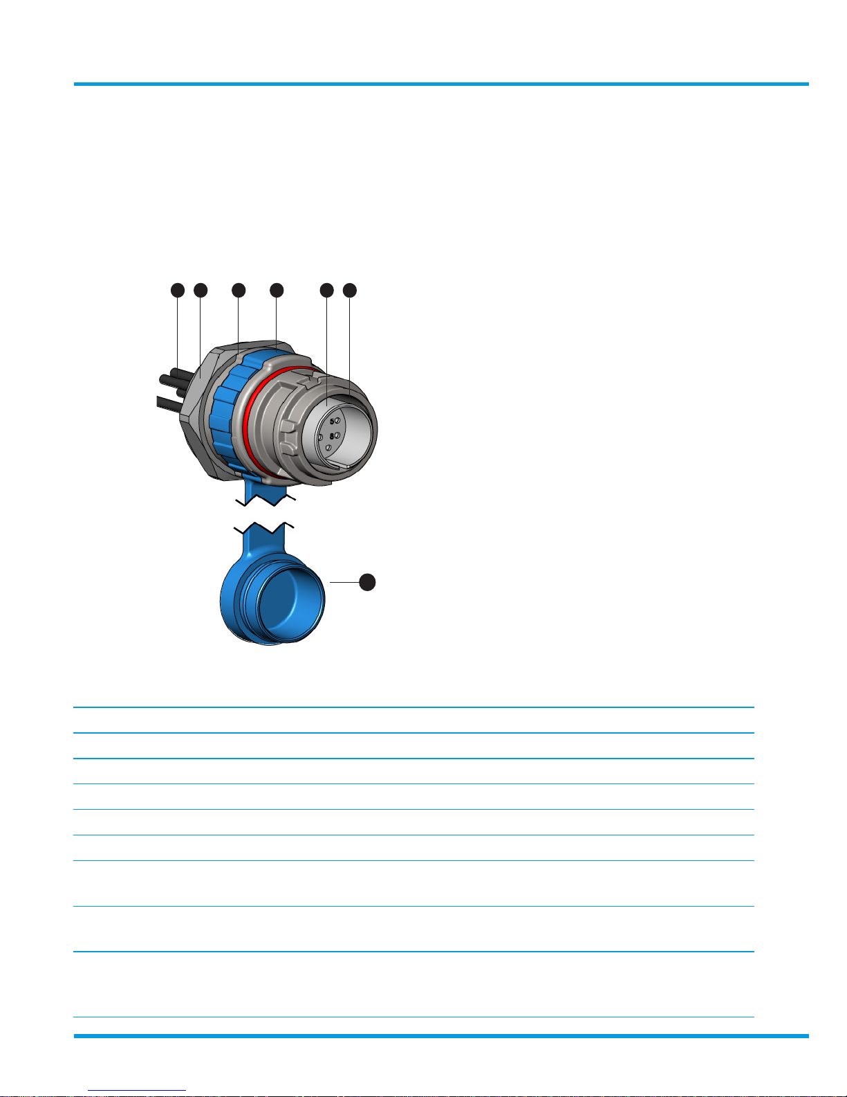
3.4 Fixed Receptacle
3.4.1 General assembly and definitions
Product options
1. Body (Plug or receptacle) Group I Stainless Steel
1. Body (Plug or receptacle) Group II Stainless Steel/Aluminium
2. Threaded entry mounting bush M20/M25
3. Locking ring with ingress seals
4. Ingress seal for surface mounting
5. Ingress protection cap
6. Pre-wired encapsulated connections 1.5 mm
2
X 1M / 2M / 3M (L)
2.5 mm
2 X
1M / 2M / 3M (L)
7. Female contact insert 10 way/4 way
(Security code to be specified)
8. Contacts Pins/Sockets
(Leading earth pin when specified)
(Lagging pilot pin when specified)
TX3706. 03
Fixed Receptacle
Bush mounting onto Ex e or Ex d housing (Section 3.4.2)
6 2 3 1 8
7
5
www.trolex.com
Page 16
16 TX3706-UM-EN-02
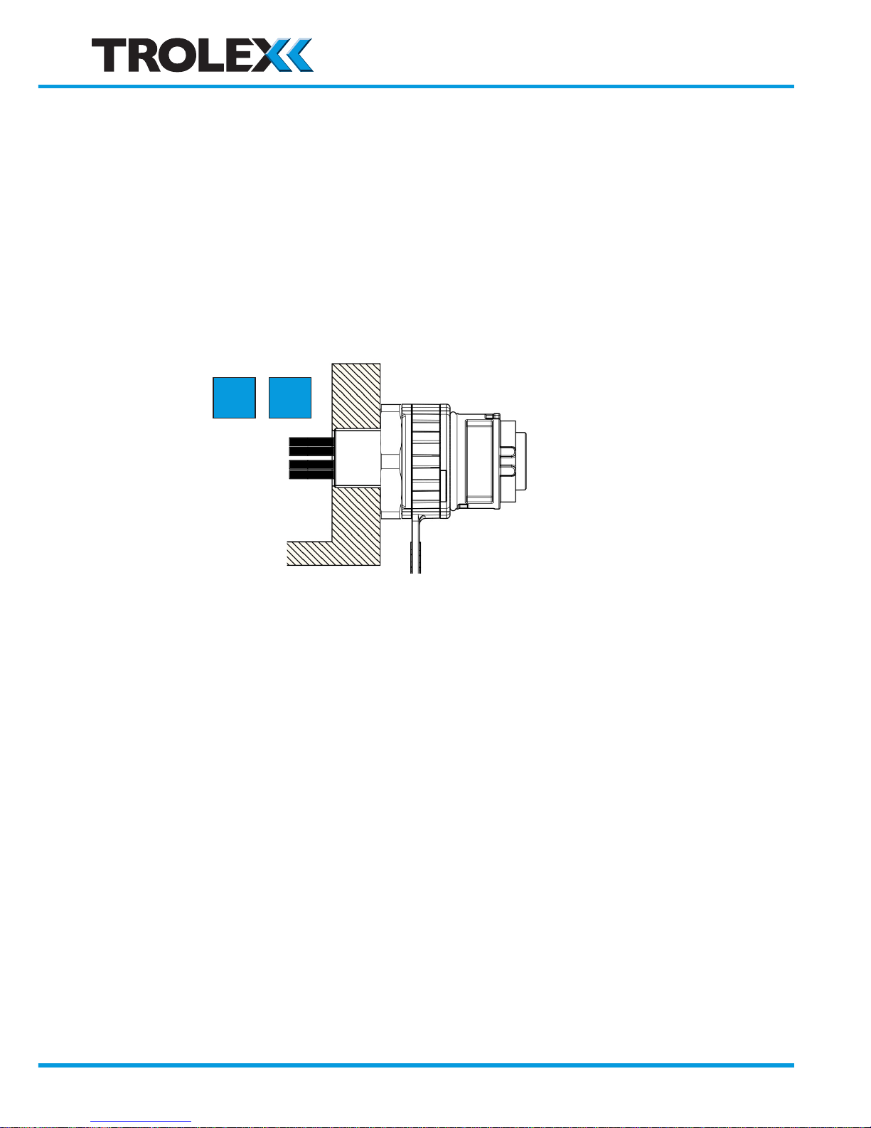
3.4.2 Ex d bush mounting
TX 3706.3...20
TX 3706.3...25
Ex e
Ex d
1. Screw the locking ring all the way home.
2. Screw the Receptacle all the way into the mounting bush on the enclosure. This must be
a minimum of five threads engaged on an Ex d enclosure.
3. Use a half-spanner to apply counter-clockwise locking force to the locking ring.
A locking ring enables the Receptacle to be radially positioned to suit user preference and
incorporates ingress seals to IP66 standards.
• Position the Receptacle to concur with any radial position of the corresponding free plug.
• Align Receptacles for best visual appearance
• Locks against the effect of rotational forces which may occur from the connecting cable.
www.trolex.com
Page 17
Engage Ex d Protection
Break Ex d Protection
Separate IP30 on Socket
TX3706-UM-EN-02 17
TX3706 • User Manual
4. Operation
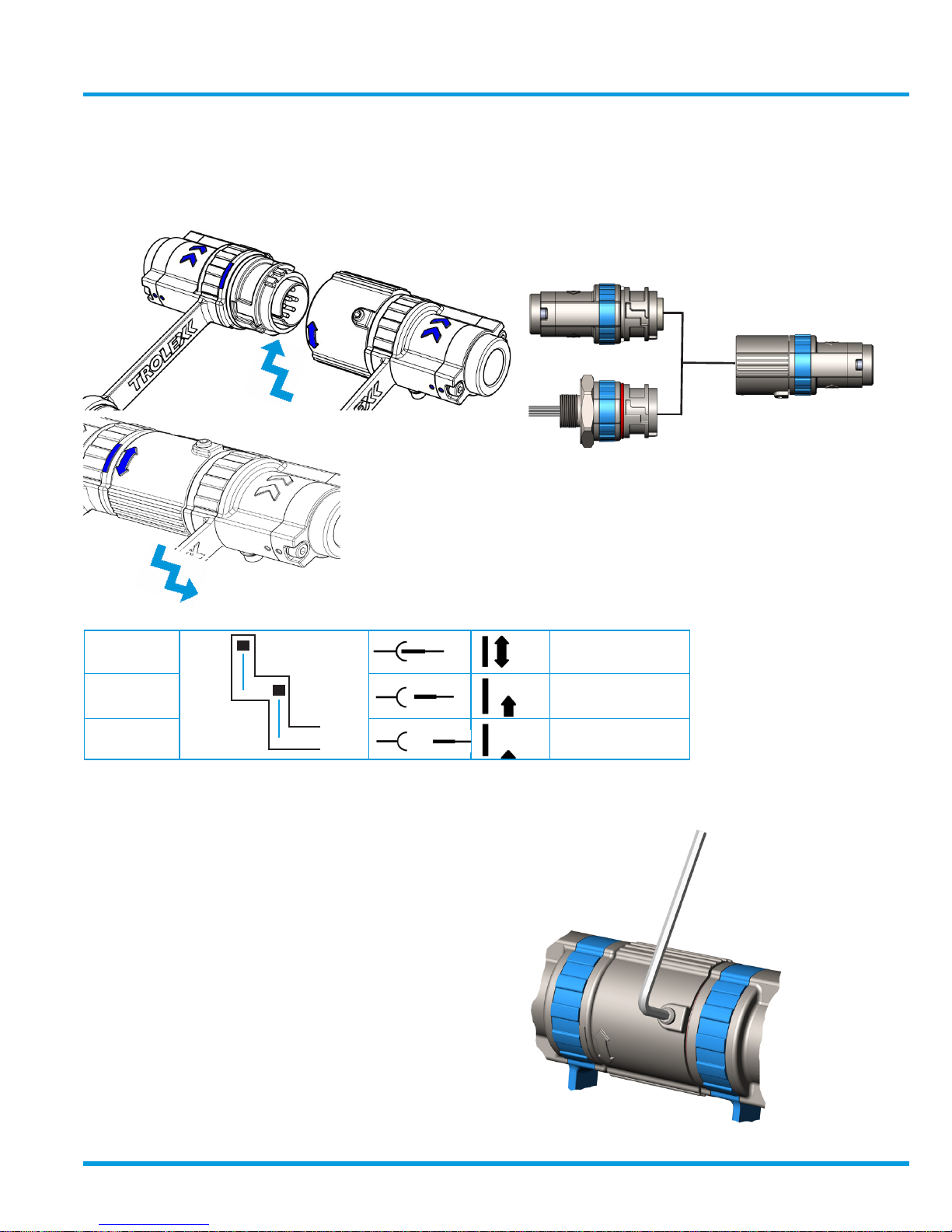
4.1 Engage and separate
Locking Screw
→
→
Line Receptacle
TX3706.2
Fixed Receptacle
TX3706.3
Line Plug
TX3706.1
The locking screw must be tightened to complete the
connection process giving full Ex d protection.
www.trolex.com
Page 18
18 TX3706-UM-EN-02
4.2 Safety Precautions
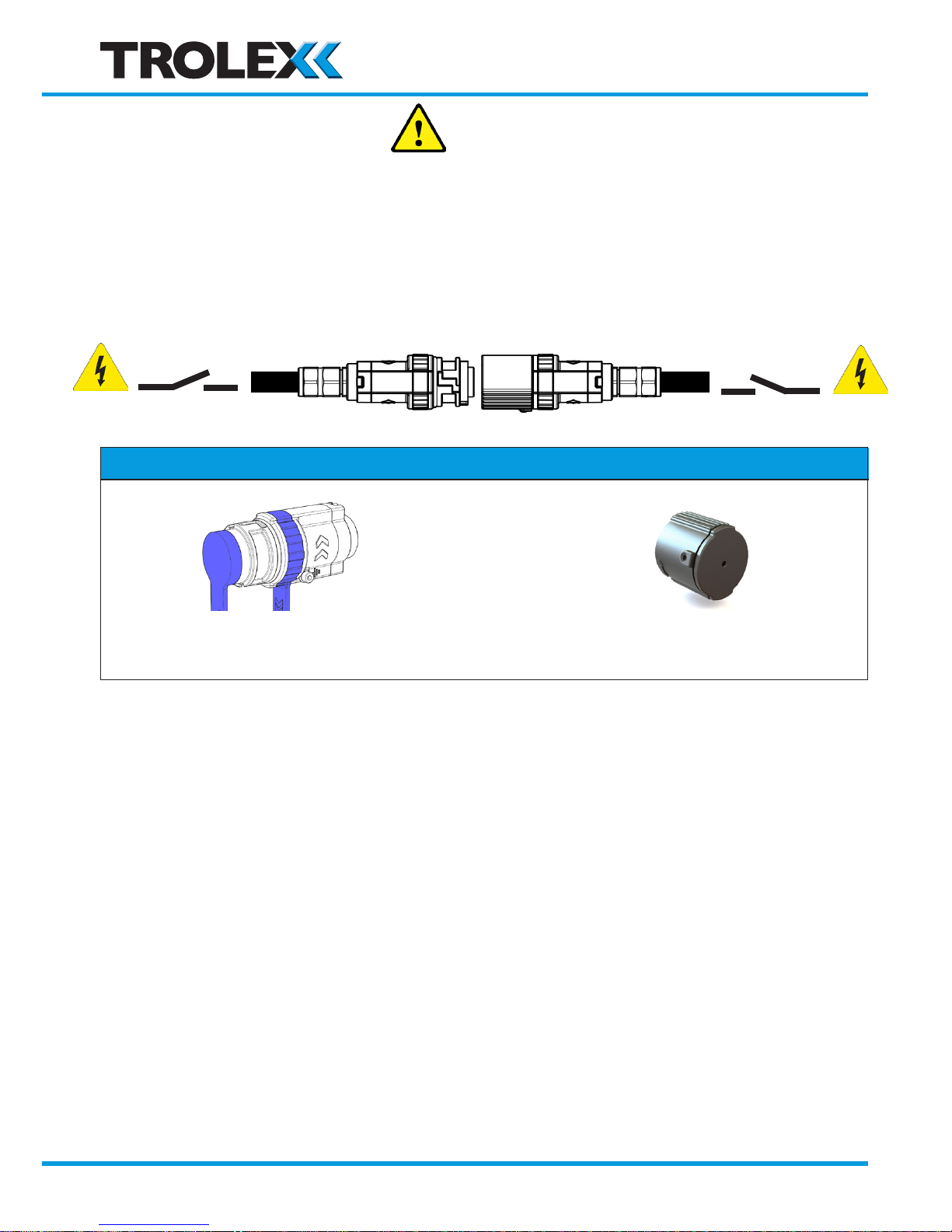
There are three methods of safety protection depending upon the application and local safety
regulations.
4.2.1 Isolate elsewhere
Isolate all electrical power at source BEFORE separation
Checkpoint
IP65 Ex d + IP66
Fit the rubber ingress protection cap when
separated.
Fit an Ex protection cap if the system
power is to be reinstated.
www.trolex.com
Page 19
TX3706-UM-EN-02 19
TX3706 • User Manual
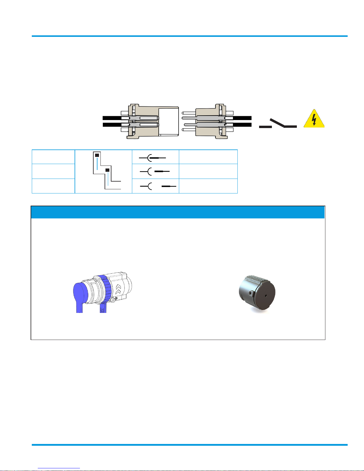
4.2.2 Pilot circuit interlocking
Automatic isolation of the power source during separation using one of the connector
contacts for interlocking a pilot switching circuit.
• Fit a lagging pilot pin TX 3700.032.15 or TX 3700.032.25
Engage Ex d Protection
Break Ex d Protection
Separate - - -
IP65 Ex d + IP66
Fit the rubber ingress protection cap when
separated.
Fit an Ex protection cap if the system
power is to be reinstated.
Checkpoint
• The pilot relay will isolate the power source slightly in advance of the main contacts
during separation
• Breaking of the pilot contract will take place under Ex d protection
• The pilot circuit must be de-energised along with the power source.
→
→
www.trolex.com
Page 20
20 TX3706-UM-EN-02
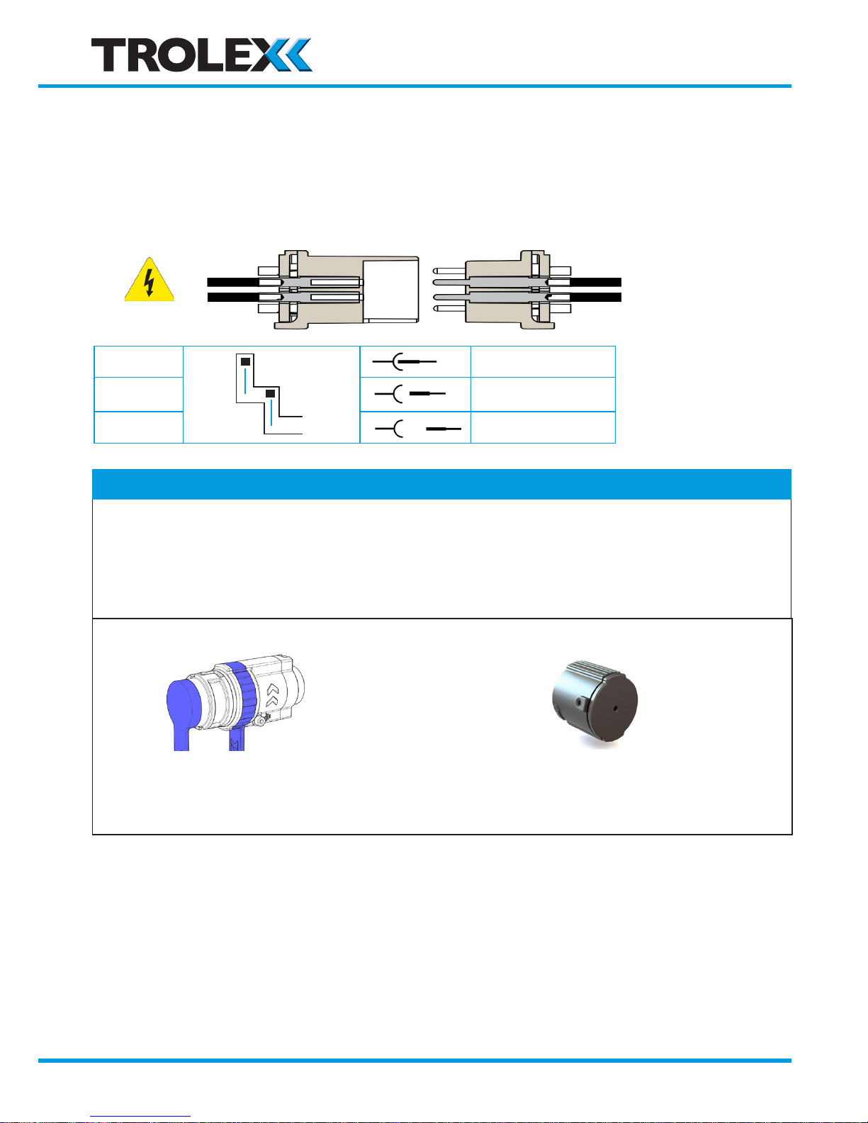
4.2.3 Live engagement
ENGAGE or SEPARATE the connector with live power in the hazardous area, is permitted for
short periods to allow maintenance or change-out of apparatus.
Power must originate from the SOCKET ONLY.
Engage
Ex d Protection
Break
Ex d Protection
Separate
IP30 on Socket
Checkpoint
Maximum Voltage . 4 way 250 V ac/dc
Maximum Voltage .10 way 80 V ac
Maximum breaking current (per contact) 1 A
Power factor Between 0.6 and 1.0
IP65 Only Ex d + IP66
Fit the rubber ingress protection cap
during temporary separation to exclude
dust and moisture.
Fit an Ex protection cap if the connection
is to remain separated after the permitted
maintenance period.
→
→
www.trolex.com
Page 21

TX3706 • User Manual
TX3706-UM-EN-02 21
Important:
• Information in this section is provided to enable users to evaluate the risk of live work.
• Live disconnection should be carried out under an appropriate permit to work system
based on the risk assessment and should be carried out in a clean and dry environment
on a temporary basis only.
• Before an Ex protection cap is fitted and whilst disconnected, the connector is no
longer Ex d or Ex tb protected however creepage and clearances of the connector meet
requirements of IEC/EN 60079-7 for the maximum rated live disconnection voltages.
Fitting Ex protection cap restores full Ex d or Ex tb protection.
• Before a rubber ingress protection cap or an Ex protection cap is fitted, live connectors will
have an IP30 rating only and whilst disconnected, both the plug and socket parts need to
be protected from mechanical damage.
• The rubber protection cap provides an ingress protection IP65 when fitted but does not
provide an enclosure meeting the requirements IEC/EN 60079-0.
www.trolex.com
Page 22
22 TX3706-UM-EN-02
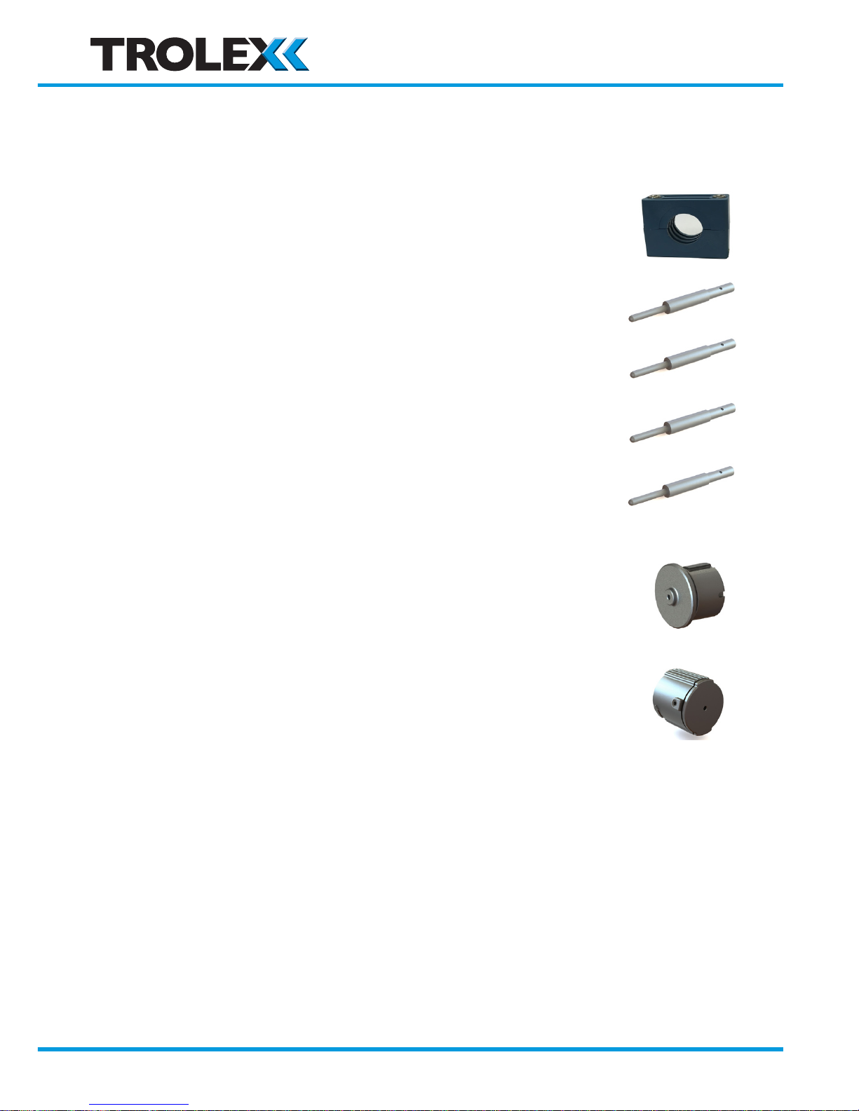
5. Accessories
Mounting clamp TX3706. 51
Leading earth pin 1.5 mm2 P5609.23.01
Leading earth pin 2.5 mm2 P5609.16.01
Live disconnect/pilot pin 1.5 mm2 P5609.23.02
Maximum current: 1 Amp
Live disconnect/pilot pin 2.5 mm2 P5609.16.02
Maximum current: 1 Amp
Ex protection plug cap
Aluminium TX3706.41
Stainless Steel TX3706.42
Ex protection receptacle cap
Aluminium TX3706.43
Stainless Steel TX3706.44
www.trolex.com
Page 23

TX3706-UM-EN-02 23
TX3706 • User Manual
6 Maintenance
No regular maintenance is required
Flame paths and ingress protection seals should be inspected at periodic intervals, in accordance
with local statutory regulations and light protective grease applied when necessary.
Disclaimers
The information provided in this document contains general descriptions and technical
characteristics of the performance of the product. It is not intended as a substitute for and is not
to be used for determining suitability or reliability of this product for specific user applications.
It is the duty of any user or installer to perform the appropriate and complete risk analysis,
evaluation and testing of the products with respect to the relevant specific application or use.
Trolex shall not be responsible or liable for misuse of the information contained herein. If you
have any suggestions for improvements or amendments, or find errors in this publication,
please notify us at [email protected].
No part of this document may be reproduced in any form or by any means, electronic or
mechanical, including photocopying, without express written permission of Trolex.
All pertinent state, regional, and local safety regulations must be observed when installing
and using this product. For reasons of safety and to help ensure compliance with documented
system data, only Trolex or its affiliates should perform repairs to components.
When devices are used for applications with technical safety requirements, the relevant
instructions must be followed.
Trademarks
© 2018 Trolex® Limited.
Trolex is a registered trademark of Trolex Limited. The use of all trademarks in this document
is acknowledged.
Patent pending.
Document history: Issue 01 -May 2016
Issue 02 -February 2018
Trolex Ltd, Newby Road, Hazel Grove, Stockport, Cheshire, SK7 5DY, UK
+44 (0) 161 483 1435 [email protected]
www.trolex.com
Page 24

Page 25

Page 26
 Loading...