

Page 1

www.trolex.com
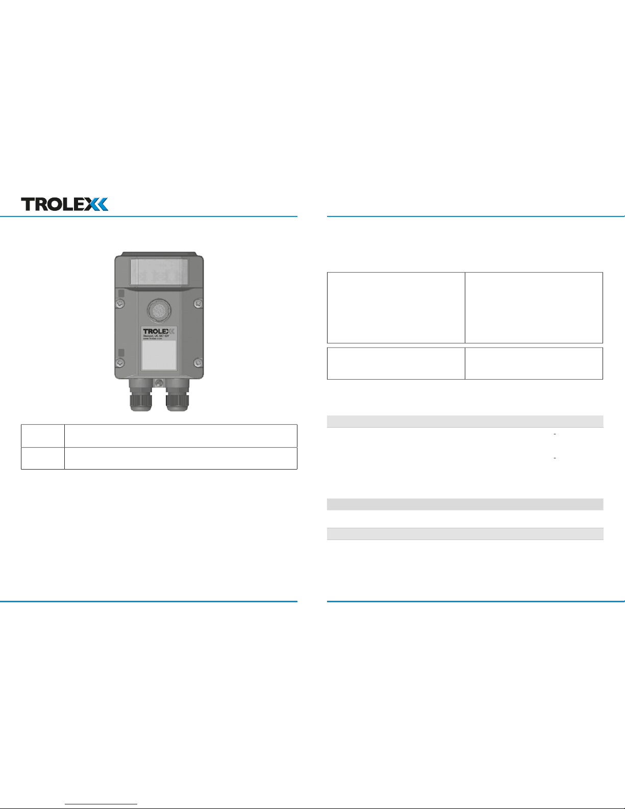
TX6351
TX6352
Page 2

P5536.1600 rev B 3
1. Product Overview 4
Equipment Required 24
Output Signal 26
Output Signal 27
Areas 30
Maintenance 48
Calibration Log 52
www.trolex.com
Page 3
P5536.1600 rev B 5
12 V dc from an
I M1
24 V dc
4-wire connection
*2-wire line powered
4 to 20 mA output
*For use with Toxic Gas Sentro eModules only
www.trolex.com www.trolex.com
Page 4
P5536.1600 rev B 7
Ambient temperature limits
Ambient pressure
A maximum of two per terminal
A maximum of 2.5 mm²
Vibration limits
Vibration limits (IEC 60079-29-1):
acceleration peak
www.trolex.com www.trolex.com
Page 5
P5536.1600 rev B 9
Alarms
with an LED indicator.
to the type of sensor, determined by the sensing
Automatic setting of STEL and TWA limits to EH40
www.trolex.com www.trolex.com
Page 6
P5536.1600 rev B 11
the module is loaded into the module bay.
All Sentro Modules have two output alarm signals for GENERAL alarm and HIGH
www.trolex.com www.trolex.com
Page 7
P5536.1600 rev B 13
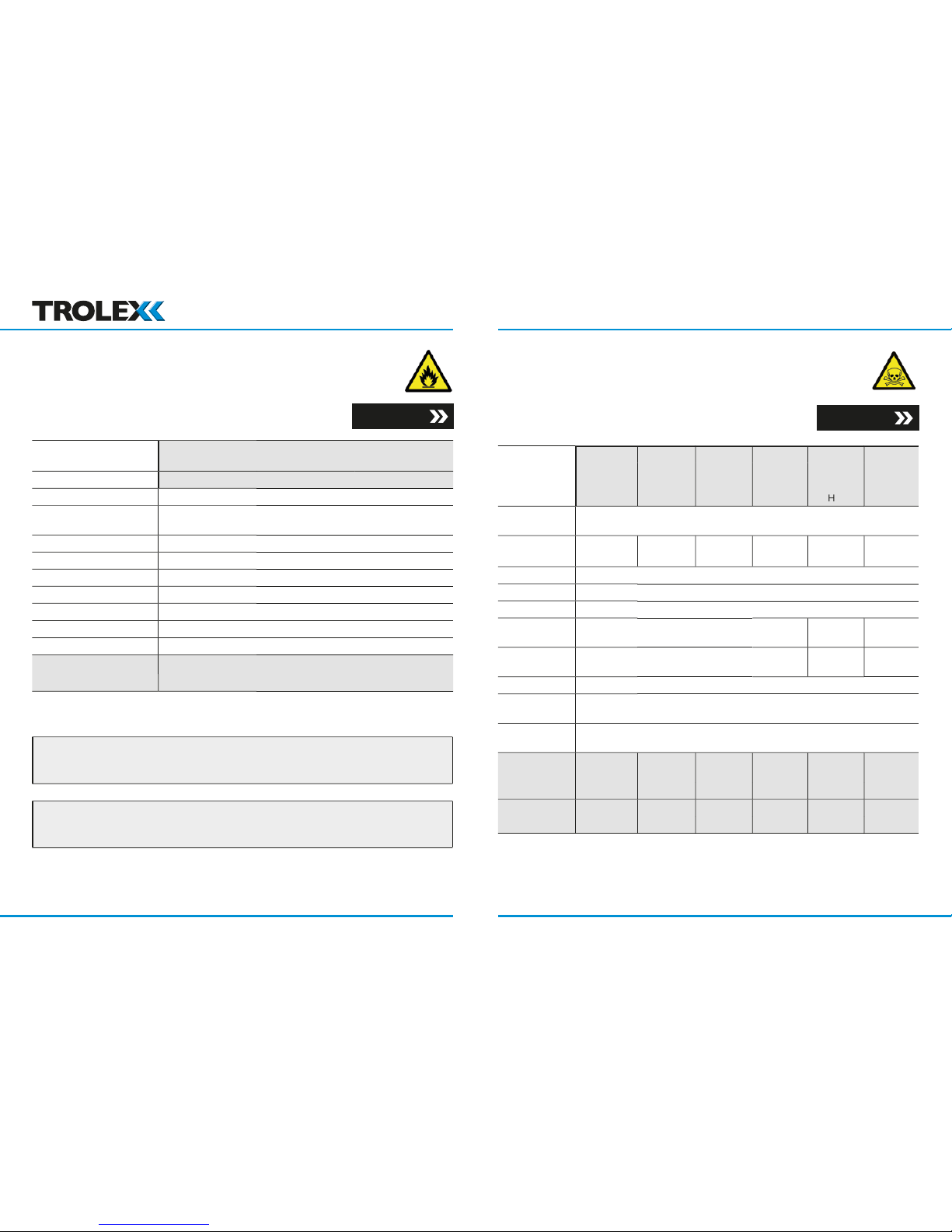
terms of %LEL or %volume.
Warm up time
Section 4.4.5
time t(63)
time t(90)
temperature
Section 4.4.5
www.trolex.com www.trolex.com
Page 8
P5536.1600 rev B 15
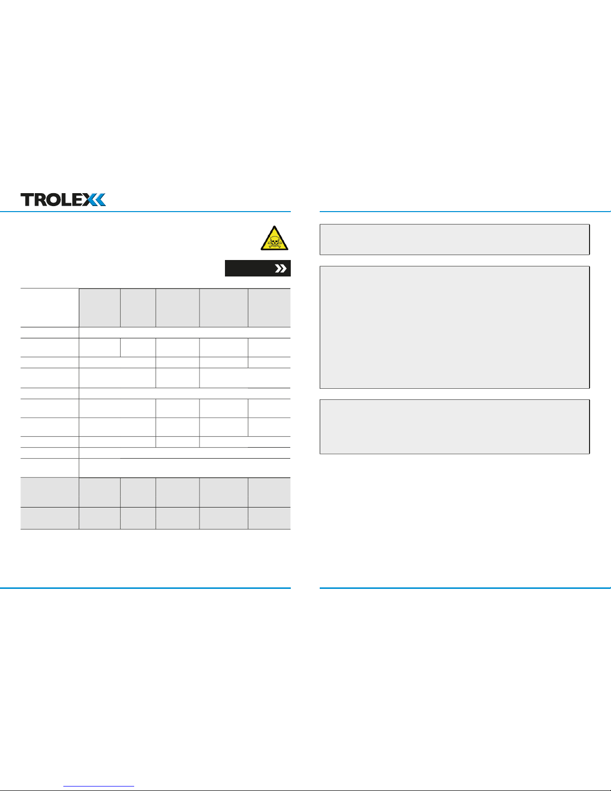
t(63)
t(90)
2 years
temperature
All values listed are nominal and slight variations may occur depending upon operating
to restore stability. Do not calibrate until the output signal is steady.
weeks. For other gas sensors Trolex recommends that this is carried out in accordance
with best practice for the industry where the gas sensor is being used, and should take into
Section 4.4.5
www.trolex.com www.trolex.com
Page 9
P5536.1600 rev B 17
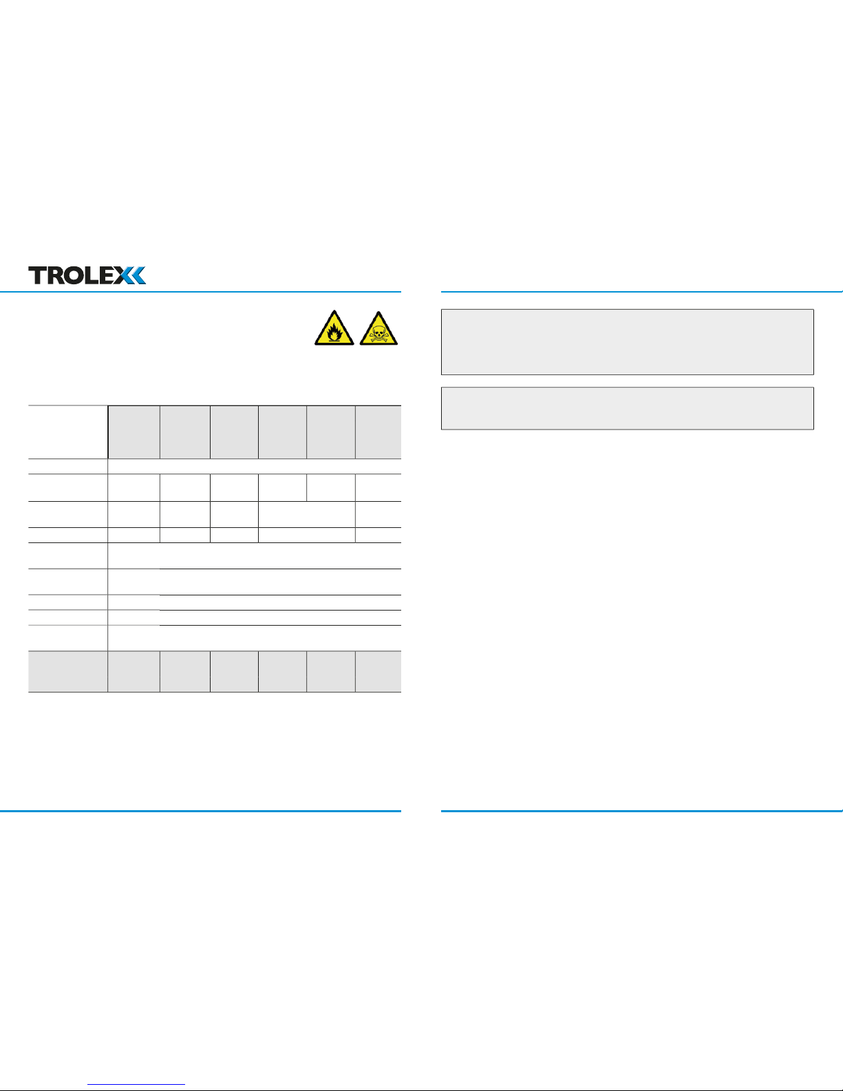
t(63)
t(90)
temperature
www.trolex.com www.trolex.com
Page 10
P5536.1600 rev B 19
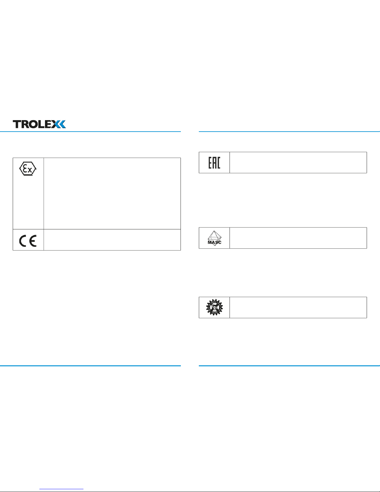
– Prior to installation, it is essential that the user refers to
the relevant certifi cate to ensure that the termination and cable
the application. Copies of certifi cates are available from
www.trolex.com.
ATEX directive 94/9/EC
the termination and cable parameters are fully complied with and are compatible with
the application. Copies of certifi cates are available from Trolex.
www.trolex.com www.trolex.com
Page 11
P5536.1600 rev B 21
Australia (IECEx):
Ci = 0.38 μF plus the Ci of the external sensors connected to the
rModule
part b can be satisfi ed
the termination and cable parameters are fully complied with and are compatible with
the application. Copies of certifi cates are available from Trolex Ltd.
www.trolex.com www.trolex.com
Page 12

P5536.1600 rev B 23
the equipment must not be installed where there is possibility of an oxygen enriched
which may displace the subject gas being monitored. Steam laden atmospheres and
After this point, the output becomes non-linear and may erroneously indicate that the
with the same 6-digit number following “MDR”, the equipment is design registered. This
www.trolex.com www.trolex.com
Page 13
P5536.1600 rev B 25
who have specialised knowledge of the plant or installation and of the principles of gas
where gas may accumulate or where a source of gas release is expected to occur. This
way, the earliest possible warning of a gas release can be given to initiate shutdown
A very important part of an e cient gas monitoring system is the training of plant
the commencement of a working period.
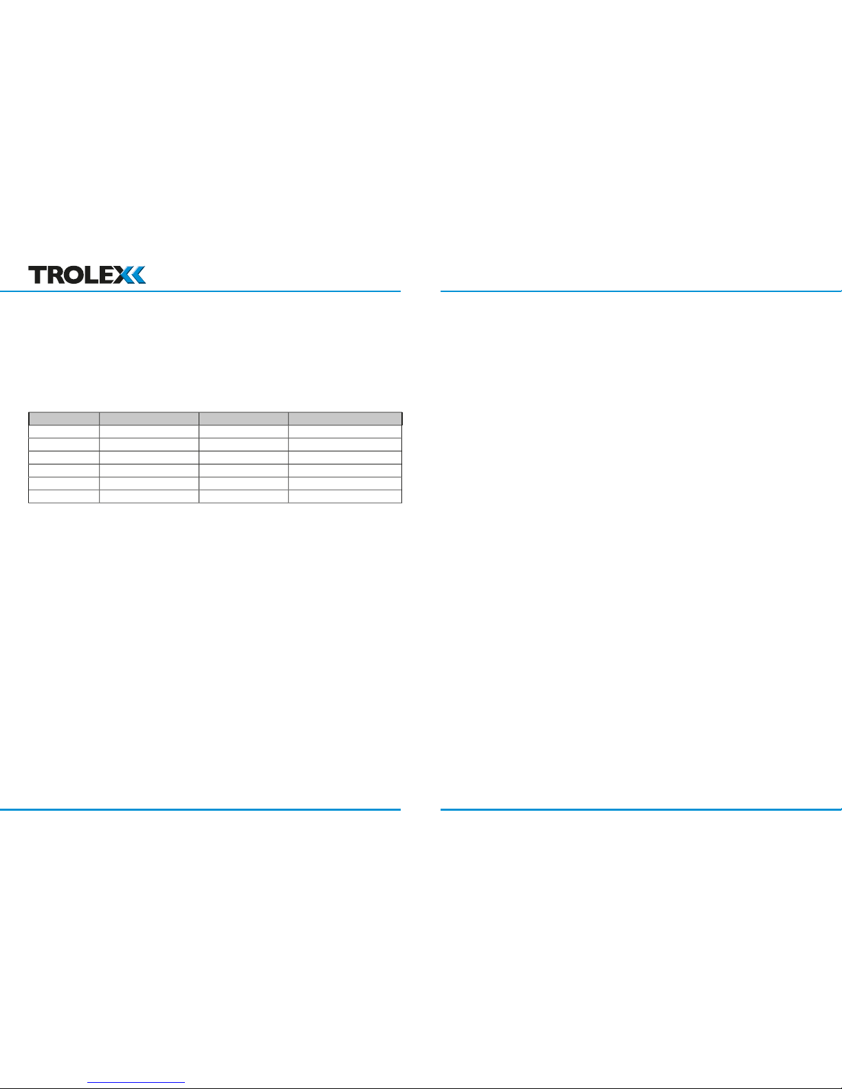
Ammonia
Acetylene
www.trolex.com www.trolex.com
Page 14
P5536.1600 rev B 27
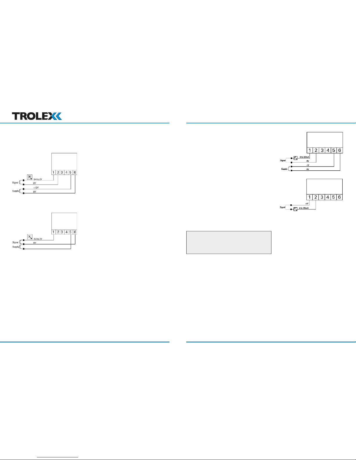
Signal
A low impedance two-wire voltage output
the length of the cable and the resistance of
the cable cores – the current fl owing in the 0 V
Alternatively, the sensor may be powered by a
Signal
to also power the sensor. No separate power
www.trolex.com www.trolex.com
Page 15
P5536.1600 rev B 29
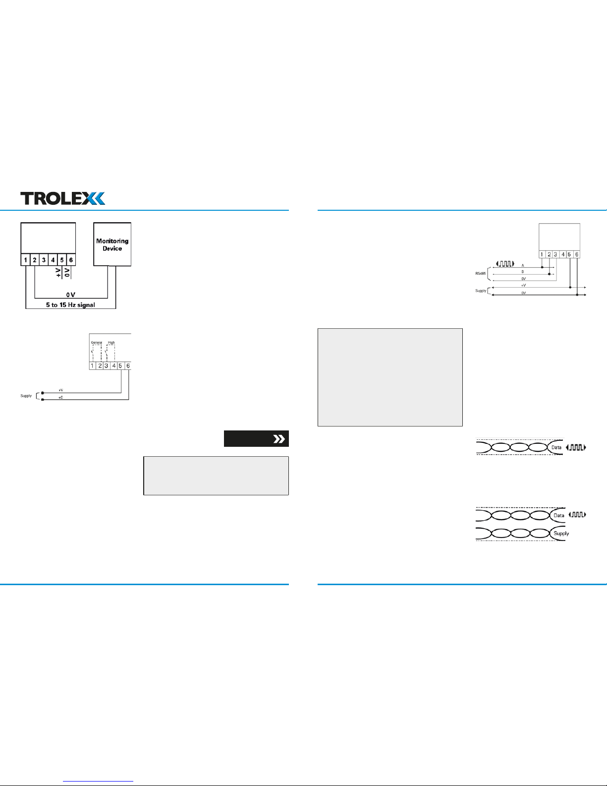
A square wave, frequency variable output that
A pull up resistor may be required at the
Section 4.4.3
the duty label of the sensor.
RS485
Trolex proprietary
Modbus
32
1,000 m
www.trolex.com www.trolex.com
Page 16
P5536.1600 rev B 31
Areas
with approved monitoring apparatus.
the Sentro certifi cation parameters.
Apparatus
www.trolex.com www.trolex.com
Page 17
P5536.1600 rev B 33
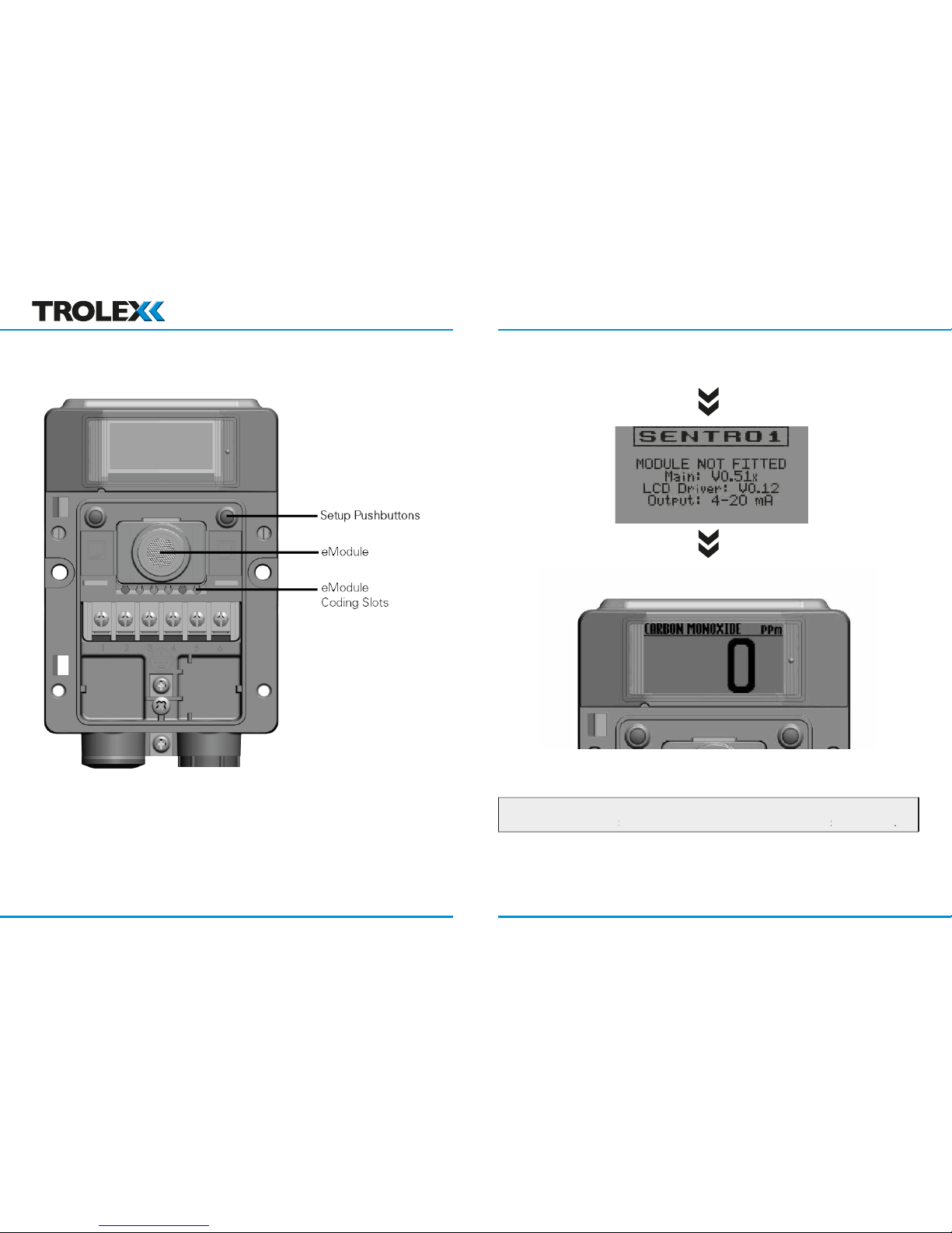
hand key
and Select/Change is the
hand key
www.trolex.com www.trolex.com
Page 18
P5536.1600 rev B 35
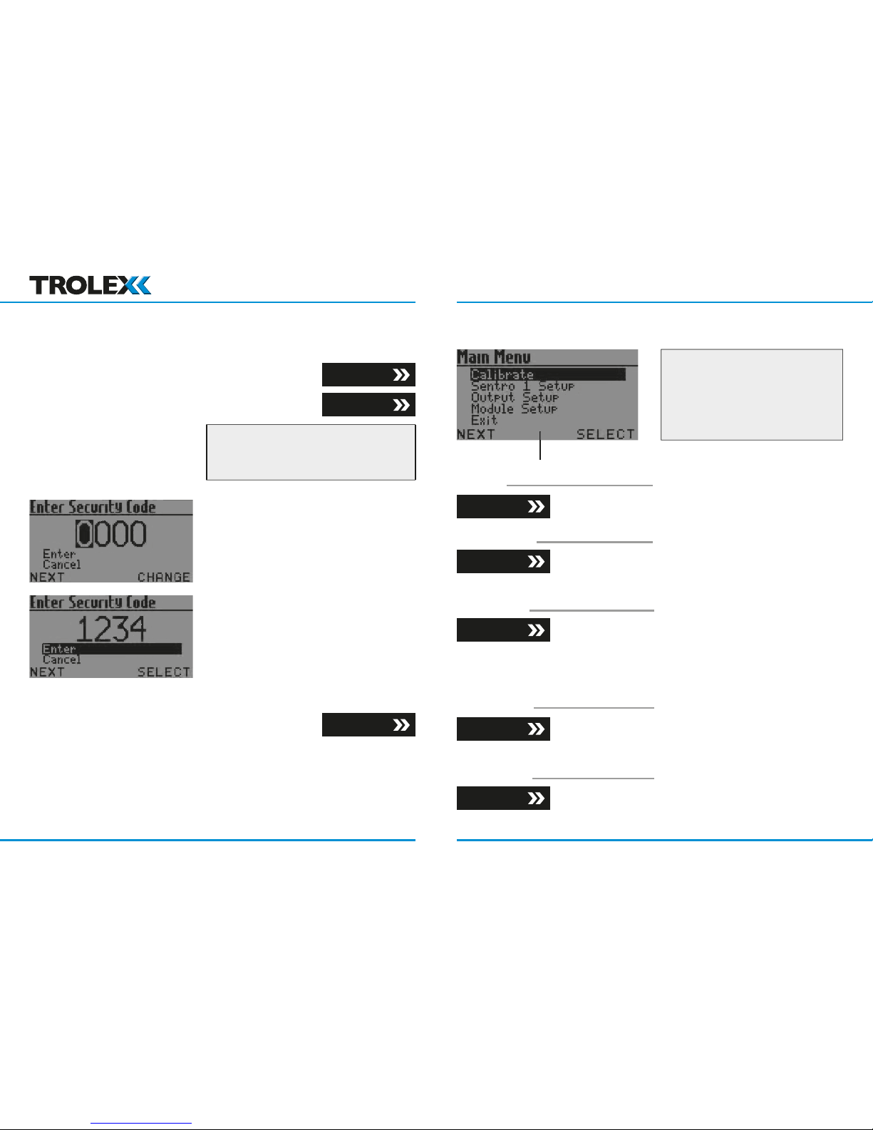
key to enter the Main Menu
with the power applied.
A security code may be requested:
key to increment the digits
key to select Enter and return to
Section 4.4
Section 4.3
Section 4.4
Prompt Bar
Modbus Setup
the Main Display if no commands are
to allow the gas value to stabilise.
Section 4.4.1
Section 4.4.2
Section 4.4.3
Section 4.4.4
Section 4.4.5
Alert Setup
Set Relay 1 Mode
Set Relay 2 Mode
(L)
(R)
www.trolex.com www.trolex.com
Page 19
P5536.1600 rev B 37
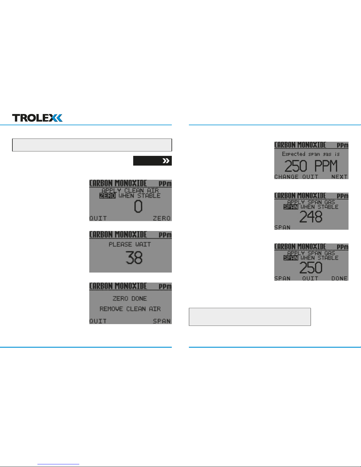
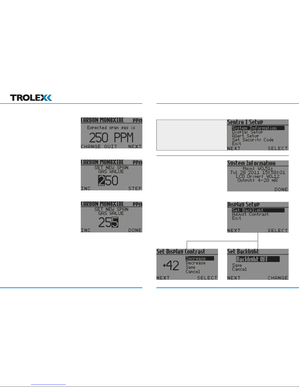
• Follow the prompt bar
and screen instructions
• Go to Span
Section 5.2
• Follow the prompt bar
and screen instructions
• Key Done and return
to the Main Display
and
together to quit and return to the main display.
www.trolex.com www.trolex.com
Page 20
P5536.1600 rev B 39
the actual Test Gas value:
• Follow the prompt bar
and screen instructions
Press
to continue with the
normal span calibration
(previous page)
• The display backlight illumination
may be set to on, or o , to reduce
power consumption.
(TX6351 only)
• The contrast of the display
may be set for best
visual appearance.
www.trolex.com www.trolex.com
Page 21
P5536.1600 rev B 41
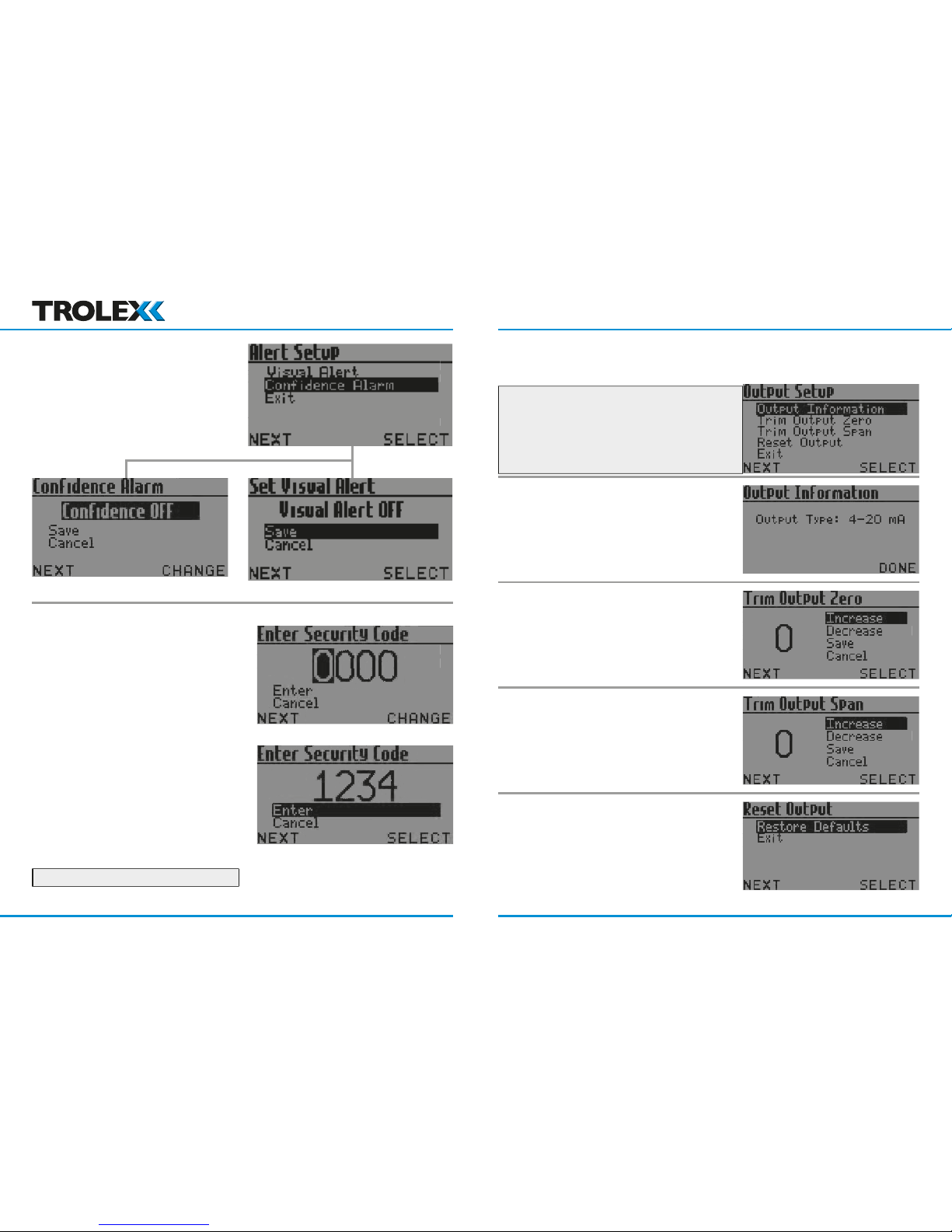
Alert Setup (TX6351 only)
• The integral GENERAL and HIGH
visual alarms can be set to
ON or OFF.
• The ‘confi dence’ condition fl ash
can be set to ON or OFF.
• A four digit security code can be
entered to prevent unauthorised
access to the setup menu.
trimmed or o set.
www.trolex.com www.trolex.com
Page 22
P5536.1600 rev B 43
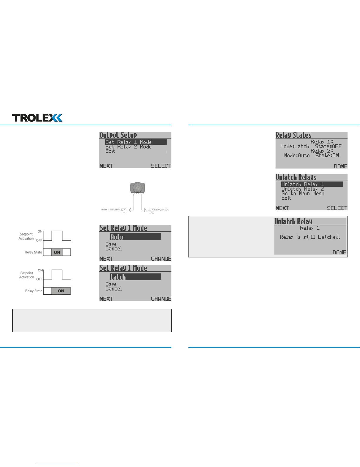
• This item will appear in the
menu on the
version only.
• The operating function of each
relay can be independently setup.
the relay will de-energise when the measured gas concentration recedes from the
to view Relay Status
A Relay will stay LATCHED if the initiating
www.trolex.com www.trolex.com
Page 23
P5536.1600 rev B 45
• The protocol characteristics required for the Modbus datacomms version
can be setup. Sentro can then be integrated into a wider communication
network or to interface with a PC or SCADA system.
Addresses
to preference.
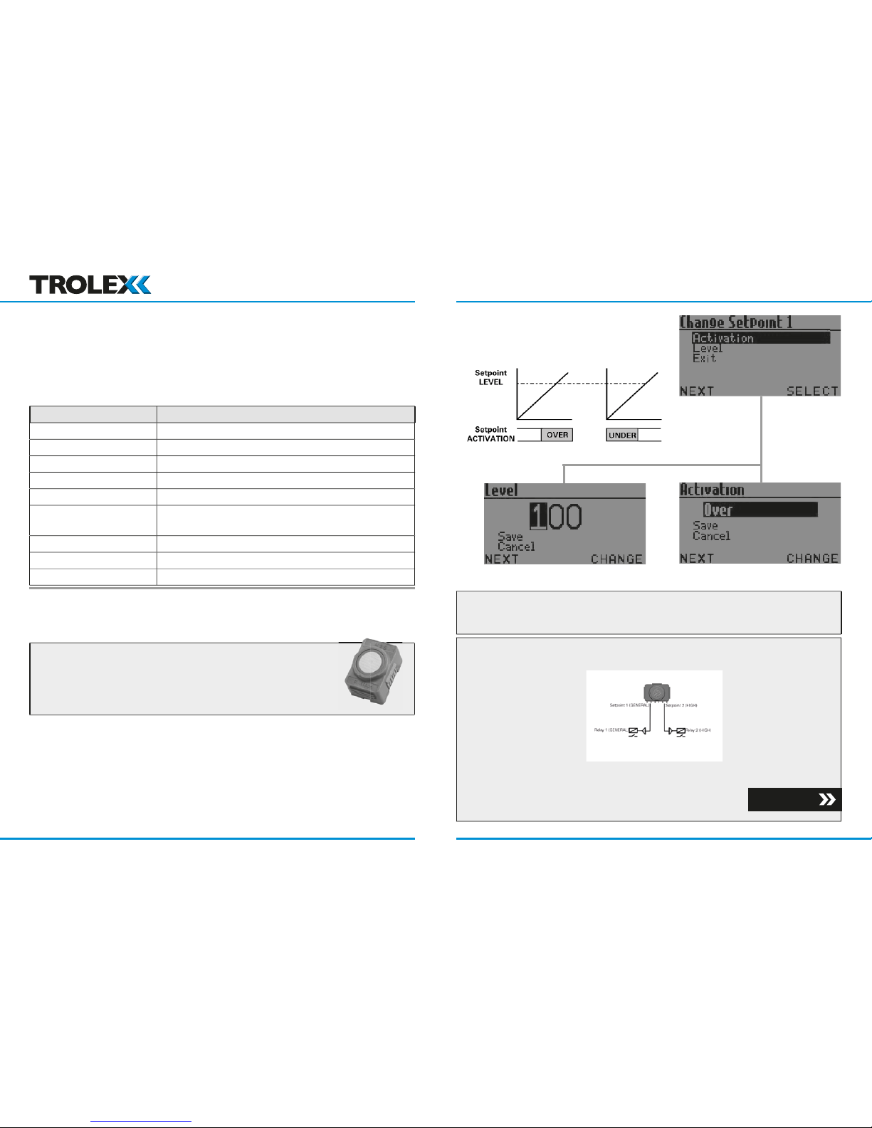
• The Sentro Module provides two adjustable setpoint output signals
• When setpoint 1 (General) is activated, the LED alarm indicators in the
display window fl ash simultaneously at a rate of about once every two
seconds. When setpoint 2 (high) is activated, they fl ash simultaneously at a
rate of about 2 per second
• The Activation mode and operating
level of the setpoints can be setup
to preference.
• The setpoint output signal data will also be available for transmission
on the RS485 Modbus version of Sentro.
• The Contact Output version of Sentro 1 is also equipped with two relays
• The Activation will operate in the same way
• The Relay Function mode can also be setup
Section 4.4.3
www.trolex.com www.trolex.com
Page 24
P5536.1600 rev B 47
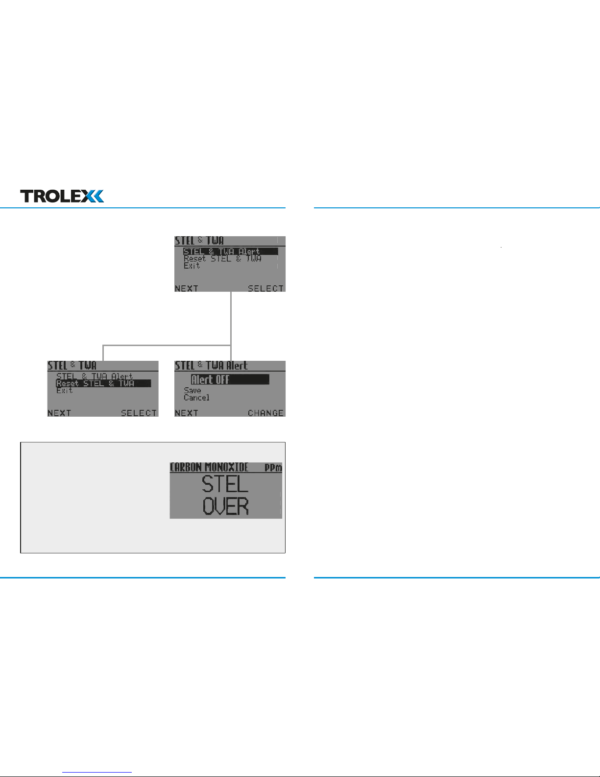
• Toxic gas sensing Sentro eModules
are equipped to automatically calculate
STEL and TWA limits in accordance
with international EH40
recommendations
• The Alert can be set to ON or OFF
• The accumulated STEL and TWA data
can be reset to zero ready for the start
of a new working period.
• STEL OVER or TWA OVER will
be displayed when limits are
exceeded.
• If the visual alarm has been enabled
then this will also activate at
level 1 when a STEL or TWA limit
is exceeded.
• For a contact output version, the STEL and TWA alert will also initiate
the Activate command for Relay 1.
www.trolex.com www.trolex.com
Page 25
P5536.1600 rev B 49
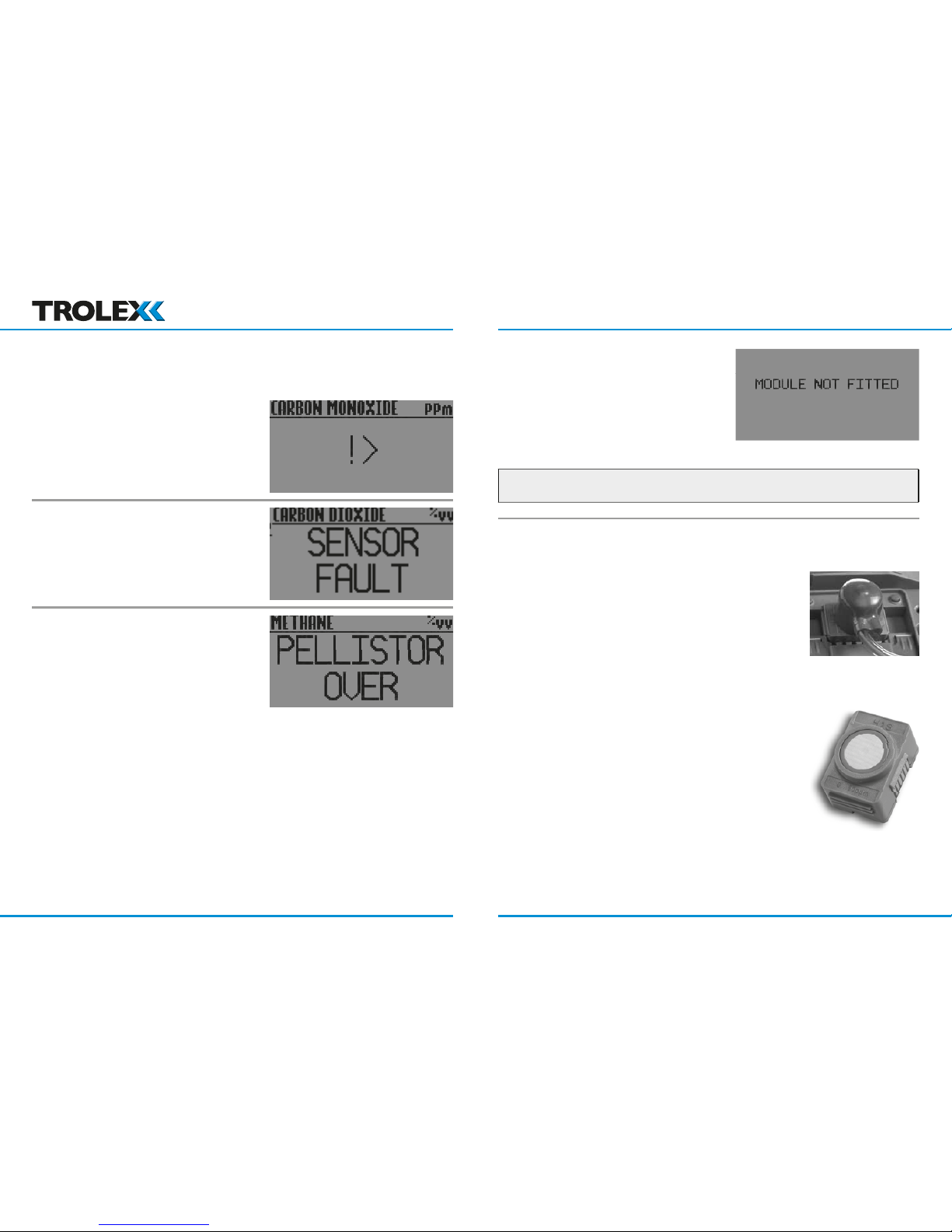
• The gas sensing concentration
exceeds 100% LEL which is the
safe working limit of the sensing
element.
• The transmitted output signal from the sensor will be clamped at full
scale to prevent ambiguous output data from being transmitted and
will latch in this condition
• The pellistor in the gas sensing module will be switched into a
PROTECT state to prevent oxidisation damage and will latch in this state.
• Check that the gas concentration has receded, then reset the module
by removing it for 2 seconds.
• The eModule has been removed
and is out for more than 10 seconds
• Under-range output signal will be transmitted by the sensor.
• Check the accuracy of the sensor at
pre-determined intervals by injecting
a test gas
• The Sentro eModules should be
changed at regular intervals to ensure
the accuracy of response
• Service history is logged within the
module and this data is used to
periodically assess its condition whenever
it is returned for servicing. Simply insert
the new module into the instrument and
return the original for checking and
calibration.
www.trolex.com www.trolex.com
Page 26
P5536.1600 rev B 51
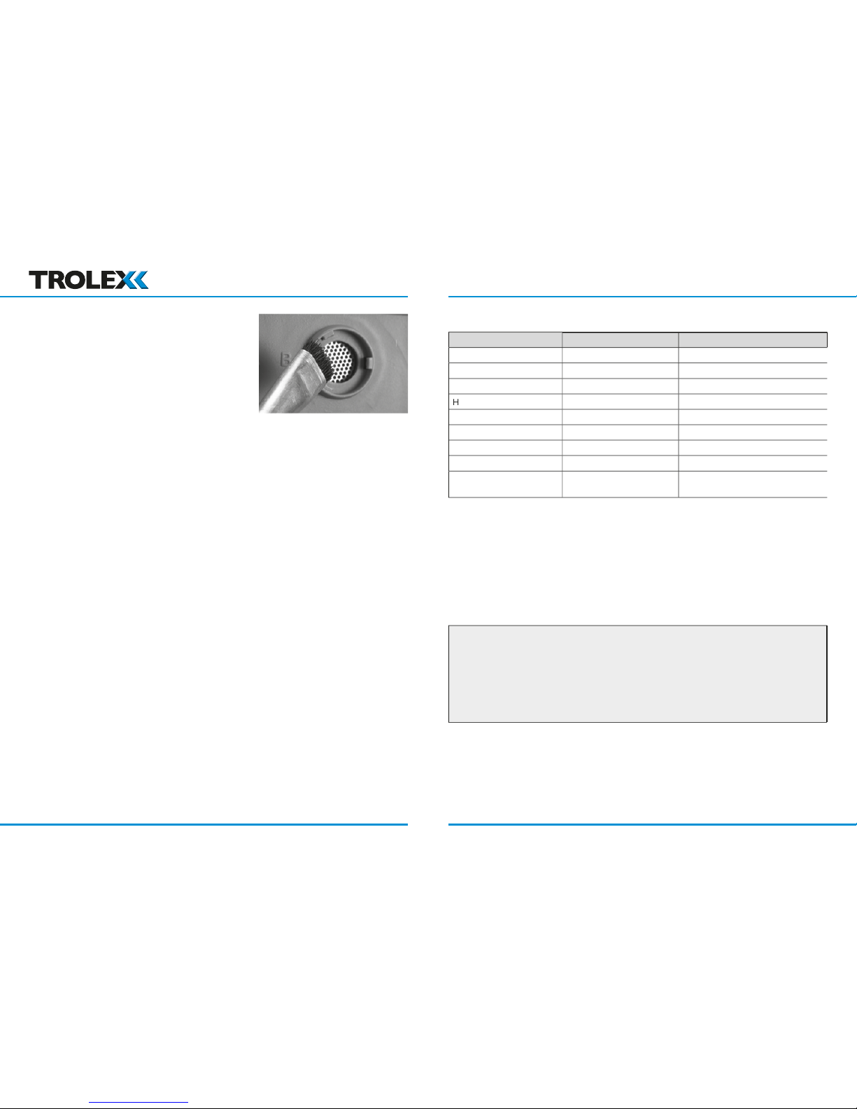
• Check the condition and clean with a
small brush to remove dust and debris
IP ratings do not imply that the equipment will detect gas, during and after
exposure to those conditions
If it is suspected that the gas inlet port has been exposed to water in
conditions that exceed IPx4, the sensor should be dried and the response of
the sensor checked.
Annual Safety Check
to gas, and the nature of the environment, so Trolex recommend that the sensors should
(Pellistor) 100% LEL
in N
in air
in air
in air
test gas must be combined with balance air if being used to calibrate pellistor
www.trolex.com www.trolex.com
Page 27
P5536.1600 rev B 53
contains materials that can be
is recycled in accordance with local laws and bylaws for the geographic area
where it is located. The end of its useful life is to be determined by the owner/operator
is recycled by licenced waste
is located.
All pertinent state, regional, and local safety regulations must be observed when
with documented system data, only Trolex or its a liates should perform repairs to
to Trolex
www.trolex.com www.trolex.com
Page 28

P5536.1600 rev B 55
A 11 - 12- 2015 4262
www.trolex.com www.trolex.com
Page 29

 Loading...