

Page 1
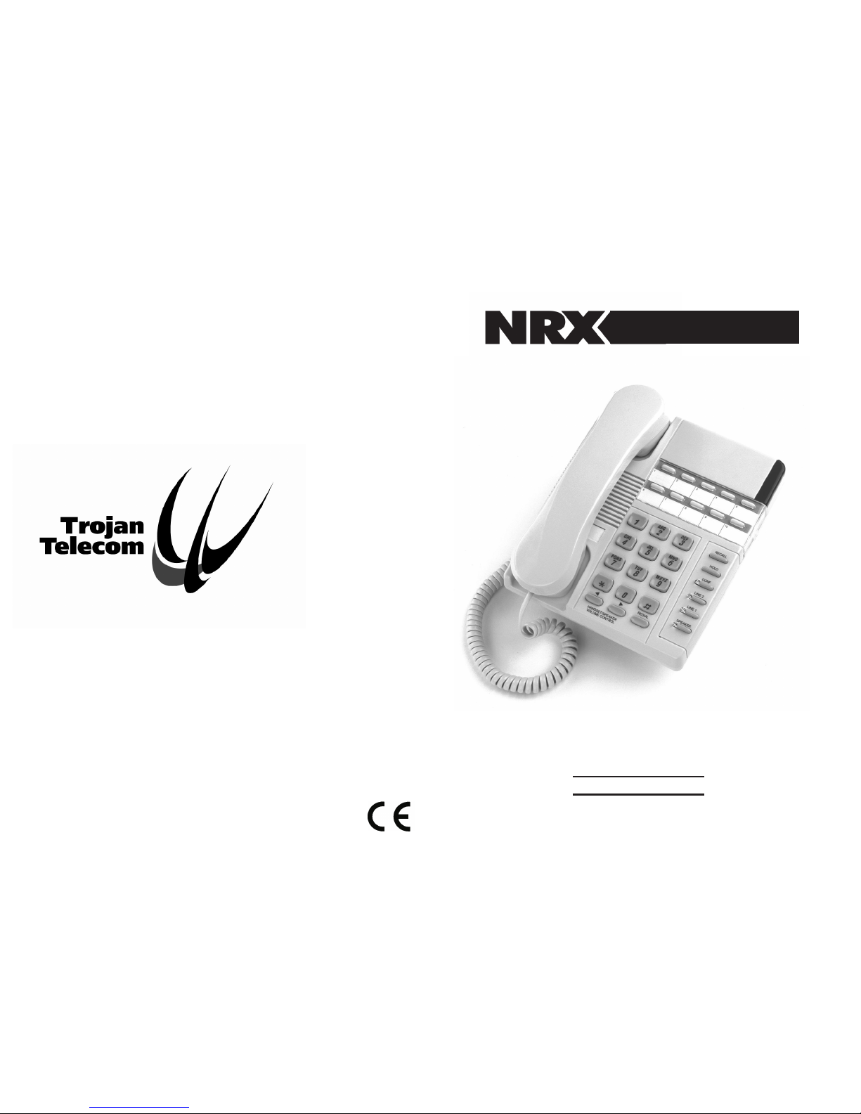
REF: NRX1171105
Ist Floor
Amphenol Complex
Thanet Way
Whitstable
Kent
CT5 3JF
ENGLAND
Tel: (+44) (0)1227 275357 Fax: (+44) (0)1227 272932
e-mail: [email protected]
USER GUIDE
NRX 4
ww
w.
n x
-te
l
eco
m
.
c
omr
Page 2
1. INSTALLATION
2. OPERATION
2.1 Dialling
2.2 Two Line Facility
2.3 Hold
2.4 Incoming Calls
2.5 Conference Facility
2.6 Programming The Memory Buttons
2.7 Memory Dialling
2.8 Privacy (Muting the microphone during conversation)
2.9 Modem/Data Connection Socket
2.10 Message Waiting
2.11 Recall Facility
2.12 Last Number Redial
2.13 Speakerphone
2.14 Headset Facility
2.15 Adjustable Ringing Volume
2.16 Adjustable Ringing Tone Pitch
2.17 Hearing Aid Compatibility
3. WALL MOUNTING THE UNIT
4. APPROVED USE
5. CE APPROVED
6. NUMBER OF PHONES THAT CAN BE CONNECTED
7. WARRANTY
Contents
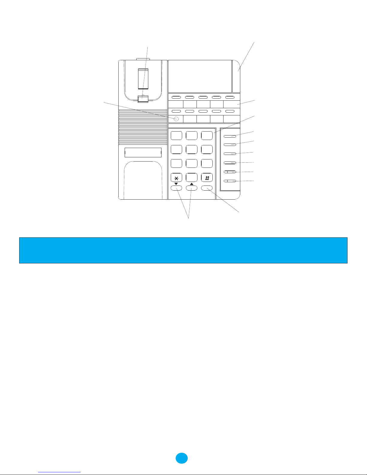
The layout of your NRX-4
1
Number Keypad
Line 2 Button
Conference Button
Line 1 Button
Ring Indicator
Wall Mount Tab
Volume Control Buttons
Redial Button
Speakerphone/Headset Button
Hold Button
One Touch
Memory Buttons
REDIAL
CONF
HOLD
LINE 1
SPEAKER/HS
Tel No:
EXT:
0
4
7
1
6
5
8
9
2 3
ABC DEF
MNOJKL
GHI
TUVPQRS WXYZ
LINE 2
RECALL
Recall Button
Program Button
Under memory Label
Page 3

3
1. INSTALLATION
.
2. OPERATION
2.1 Dialling
The NRX 4 telephone requires no batteries to be fitted as the
memories are stored in EEPROM solid state memory which
does not require battery backup.
Connect one end of the coiled cord to the handset and the
other end to the socket at the left of the base unit. Replace
the handset on the cradle.
Connect the two telephone line cords to the sockets at the
back of the unit and to the telephone sockets.
Lift handset to check for dial tone
Lift the handset or press speaker button. The telephone will
automatically seize the first free line.
Dial the number.
To terminate a phone call, simply replace the handset or
press the speaker button again.
Installation & Operation
2.2 Two Line Facility
2.3 Hold
2.4 Incoming Calls
The telephone automatically selects the first free line
when the handset is lifted or the speaker button depressed.
The line in use is indicated by a red LED on the line
button and indicates use both by the telephone and any
parallel telephones on the line.
During the course of a conversation the line can be put on
Hold by simply pressing the hold button. A green LED
will light on the line button concerned. In this state, a call
can be answered or set up on the other line.
The call can be released from its held state by pressing the
appropriate line button.
Incoming calls on either of the lines are indicated by a
flashing red LED on the line button together with the ringing
tone and flashing of the main ringer indicator (Top right
corner of the telephone).
2.5 Conference Facility
It is possible to set up a three party conference call as
follows:
2
Operation
- Set up or receive a call
- Put this call on hold by pressing the hold button
- Set up or receive a second call on the other line
- Press conference button to establish a three party call
- Replace the handset or press speaker button to release
both lines.
If you wish to release only one line from the conference,
press the line button for the line you wish to maintain.
This will release third part on the other line.
There are 10 memory locations in the NRX 4 telephone,
which can be used to store important telephone numbers.
The following is an example of storing a number in one of the
locations:-
1. Lift the handset or press the 'Speaker' button once.
2. Press the 'PROGRAM' button. (this is concealed under
memory label)
3. Enter the telephone number for storing. After the
number has been entered, press the 'PROGRAM' button
again.
4. Select one of the direct memory locations for storing the
number.
5. Repeat steps 2 to 4 for successively storing more than
one telephone number. When all numbers have been
2.6 Programming Memory Buttons
stored replace the handset.
The programming can be enabled and disabled by
means of the following key sequence:-
1.1 To disable the programming: [STORE] [VOL UP]
[STORE] [0]
1.2 To enable the programming: [STORE] [VOL UP]
[STORE] [1]
To dial a telephone number that has been stored in one of
the direct memory locations:-
1. Lift the handset or press the 'Speaker' button.
2. When you hear the dial tone, press one of the memory
locations for dialling from that memory.
(Muting the Microphone during Conversation)
During a telephone conversation, you may switch off the
microphone in the handset by pressing the Mute button on
the handset. As long as the handset Mute button is
pressed, the microphone mute function is activated.
Releasing the handset Mute button will re-enable the
microphone for conservation.
2.7 Memory Dialling
2.8 Privacy
SPEAKER/HS
HOLD
CONF
HOLD
LINE 1
SPEAKER/HS
LINE 2
SPEAKER/HS
0
4
7
1
6
5
8
9
2 3
0
4
7
1
6
5
8
9
2 3
SPEAKER/HS
Page 4

5
2.9 Modem/Data Connection Socket
The NRX 4 telephone has an addition socket marked
MODEM, which allows the user to connect an extra
telephone, modem or fax machine to the telephone line.
This socket is at the back panel of the base cabinet and has
a removable plastic cover.
2.10 Message Waiting
The NRX 4 has a built in LED and neon lamp for message
waiting indication. This is compatible with various PABX
systems providing such features. A Message waiting switch
is built inside the switch compartment located on the base
bottom. This switch enables the LED to detect two
different line reversal signals by selecting switch position 1
or 2.
For 90V DC or AC message waiting signalling PABX's the
neon is used for indication. Set the position of the switch
to off as the LED is not needed for indication.
The default switch position is OFF
2.11 Recall Facility
The NRX 4 is fully compatible with many telephone
network services, which provides a number of useful
.
Operation
additional facilities, including three way calling, call
diversion, call waiting etc. These can be accessed
via the RECALL button on the keypad. For further
details, please contact your local PTT Sales Office.
The Recall timing can be adjusted if required as
follows:
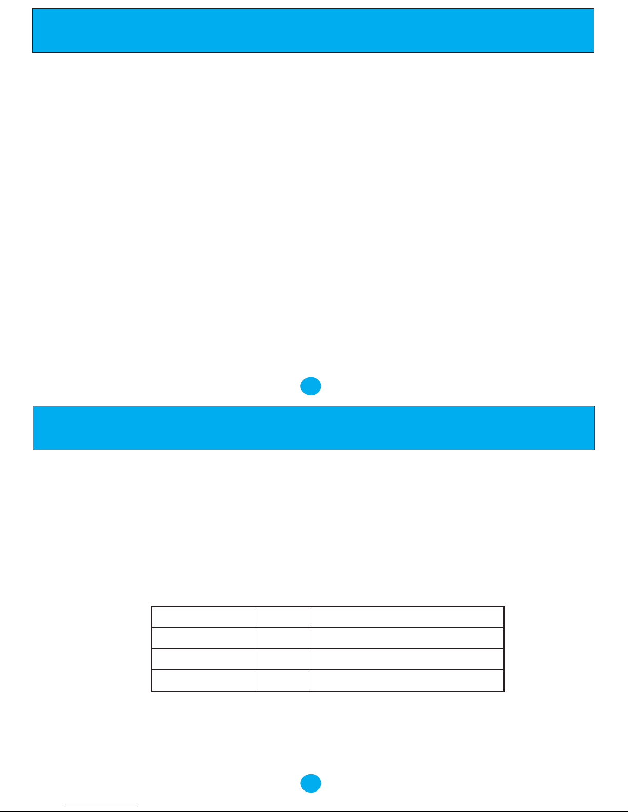
100ms (Default) - (STORE)(VOL UP)(RECALL)(1)
300ms - (STORE)(VOL UP)(RECALL)(3)
600ms - (STORE)(VOL UP)(RECALL)(6)
2.12 Last Number Redial
The last number dialled on the telephone can be
redialled by pressing the Redial button after either
lifting the handset or pressing the Speakerphone
button.
2.13 Speakerphone
The 'SPEAKER/HS' button allows the user to
operate the telephone without lifting the handset if a
headset is not connect to the telephone. Press the
'SPEAKER/HS' button once, then operate the
telephone as normal. Communication with the party
4
Operation
at the other end of the telephone line is possible using
the built in Microphone and Speaker.
2.14 Headset Facility
The ‘SPEAKER/HS’ button also enables you to use a
headset with your NRX 4 telephone. Simply connect
a headset and press the ‘SPEAKER/HS’ button once
to connect to the line. Pressing the ‘SPEAKER/HS’
button again will disconnect the telephone line and
terminate the call.
During a headset conversation, lifting the handset
will switch the unit to the handset mode. The headset
will be disabled and the handset should be used for
conversation instead. The headset mode will be
activated again by pressing the ‘Headset’ button and
replacing the handset.
2.15 Adjustable Ringing Volume
On the right of the unit is a switch, this adjusts the ringing
volume of incoming calls. From left to right it has three
positions: off, low, high. Move the switch to the position
you require. In addition to the ringing tone there is a Ring
Indicator Lamp on the unit that will flash when the
telephone is ringing as a visual indication. The Ringer
Switch does not control this Ring Indicator Lamp.
2.16 Adjustable Ringing Tone Pitch
On the right of the unit, there is also a switch that
adjusts the ringing pitch of incoming calls. From left to
right it has three positions: low, medium and high.
Move the switch to the position you require.
2.17 Hear-aid compatibility
The handset receiver is hearing aid compatible.
3. WALL-MOUNTING THE UNIT
The NRX 4 telephone can be wall mounted using the
wall mount bracket installed on the bottom of the unit.
- Dismount the wall mount bracket from the unit.
- Placing the wall mount bracket to the required
position on the wall
- Drill two holes on the wall according to the distance
as marked by two mounting holes.
- Install the two screws supplied with the unit in the
wall.
- Re-install the wall mount bracket to the bottom
cabinet for the wall mount position.
REDIAL
SPEAKER/HS
SPEAKER/HS
Page 5

7
- Position the wall mount slots on the bracket of the unit
over the two screws on the wall. Pull down and lock
into place.
- Beneath the earpiece section of the cradle you will
find a small tab. Pull this up to form the hook for the
handset.
When you are on the telephone, you sometimes need to put
the handset down for a moment. There is a special hook at
the back (top) of the unit so that you can hang the handset
on the unit when it is wall mounted, without terminating
the call.
4. APPROVED USE
The NRX 4 can be connected to the Public Switched
Telephone Network (PSTN) and compatible to
PABX's but not connected in the following manner: -
1. As an extension to a payphone.
2. On shared service line or 1+1 carrier system.
Network Compatibility
The NRX 4 has been approved persuant to
commission decision 1999/303/EC for pan-European
connection to the public switched telephone network
(PSTN). However, due to differences between the
individual PSTNs provided for in different countries,
the approval does not, of itself, give an
unconditional assurance of successful operation on
every PSTN network termination point.
In the event of problems you should contact your
equipment supplier in the first instance.
The NRX 4 has been designed to interwork with the
following networks.
Austria ü Germany ü Liechtenstein ü Spain ü
Belgium ü Greece ü Luxembourg ü Sweden ü
Denmark ü Iceland ü The Netherlands ü Switzerland ü
Finland ü Ireland ü Norway ü UK ü
France ü Italy ü Portugal ü
This product may have interworking problems with
the following networks.
Austria Germany Liechtenstein Spain
Belgium Greece Luxembourg Sweden
Denmark Iceland The Netherlands Switzerland
Finland Ireland Norway UK
France Italy Portugal
5. CE APPROVED
This unit has been EMC tested and meets the
requirements with respect to EN50081-1 emissions and
EN50082-1 immunity.
6
Approved Use
6. THE NUMBER OF TELEPHONES THAT MAY BE CONNECTED
If you connect too many telephones to your line they may not ring correctly. To determine the number of telephones that can be
satisfactorily connected to your line, add together the ringer equivalent numbers (RENs) of all the equipment you wish to
connect. If this number exceeds four, your telephones may not ring. Your NRX 4 telephone has an REN of one (1). BT
telephones have an REN of one unless otherwise marked.
7. WARRANTY
Trojan Telecom have built the NRX 4 telephone to a high standard. Our warranty reflects our belief that during it’s
working life you should not experience any mechanical failures.
However, on the rare occasion a breakdown occurs, the NRX telephone is covered by a two year warranty.
Trojan Telecom will at all times use a sensible and supportive attitude towards warrantable returns, working with you
in identifying ‘no fault found’.
The following terms and conditions apply:
1) Where we find a genuine warranty failure, Trojan Telecom will replace the faulty instrument with a one-for-one
replacement.
2) It is the responsibility of the user to return the faulty telephone to Trojan Telecom. We ask you to cover this cost
and we will return your replacement telephone at our expense.
3) We reserve the right to repair the faulty item or replace it with a similar telephone of the same make.
Warranty
Page 6
9
4) Discontinued models under warranty will be
replaced with a similar or more featured telephone.
5) We reserve the right to charge for items considered
to be chargeable under fair wear and tear.
6) User misuse or any modification carried out to the
NRX telephone by the customer is not considered a
manufacturing fault or component defect. Therefore it
is not covered by the warranty.
7) Accidental damage such as liquid spillage or user
damage will not be covered under the terms of the
warranty.
8) When returning the telephone please ensure you
fully complete the returns authorisation form, failure
to do so could cause you unnecessary delay.
The terms of this warranty do not effect your
statutory rights.
Warranty applies to UK customers only
Warranty
Faulty units should be returned to our service
centre at the following address, together with the
completed return form on the opposite page.
SERVISCOMM
UNIT 2
RED BARNES WAY
McMullen Road
Darlington
DL1 2RR
UK
8
Warranty
Date of Purchase
Model No Details of Fault
Returns Authorisation Form
Customer Details
Address: ................................. Tel No: ...................... Returns Auth No: .....................
................................................. Fax No: ......................
................................................. Account No: ..............
Trojan Telecom's full liability will extend to the cost of repair
or complete replacement of the returned item only.
 Loading...