

Trojan PULSE 500 Care Instructions And Assembly Manual
TROJAN
MY SPA CE MY TIME
®
#
1
HOME
FITNESS
SOUTH AFRICA’S
SINCE
1981
CAUTION
READ ALL PRECAUTIONS AND
INSTRUCTIONS IN THIS MANUAL
BEFORE USING THIS EQUIPMENT
KEEP THIS MANUAL FOR
FUTURE REFERENCE
1 YEAR
warranty
CALL
0861 876526
0 861 TRO JA N
STAT IONARY CYCLE CARE INSTRUCTIONS
AND ASSEMBLY MANUAL
WINNER, SHARON HAARHOFF,
USES TROJAN HOME FITNESS
EQUIPMENT AS PART OF
HER DAIL Y FITNESS
PROGRAM
SHARON HAARHOFF
AS SEEN ON
TV
PULSE 500
STATIONARY CYCLE

INDEX PAGE
1. SAFETY INSTRUCTIONS 3
2. PRE ASSEMBLY CHECK LIST 4
3. ASSEMBLY STEPS 5
4. COMPUTER FUNCTIONS 9
5. FITNESS TIPS & TECHNIQUES 13
6. CONDITIONING GUIDELINES 14
7. WARM -UP AND COOL-DOWN 15
8. FREQUENTLY ASKED QUESTIONS 16
9. PARTS LIST 17
10. EXPLODED DRAWING 18
11. TROJAN 1 YEAR LIMITED WARRANTY 20
12. TROJAN REPAIRS PROCEDURE 22

1. SAFETY INSTRUCTIONS
WARNING :
To reduce the risk of serious injury, read the following safety instructions before using the TROJAN PULSE 500 BIKE.
1. Use the TROJAN PULSE 500 BIKE only on a level surface.
2. Keep children and pets away from this equipment at all times.
3. The TROJAN PULSE 500 BIKE should not be used by persons weighing more than 150kgs.
4. The TROJAN PULSE 500 BIKE should be used by only one person at a time.
5. Be careful to maintain your balance while using, mounting, dismounting, folding, unfolding or assembling the
TROJAN PULSE 500 BIKE. Loss of balance may result in a fall and serious bodily injury.
6. Use the TROJAN PULSE 500 BIKE only as described in the manual.
7. Do not attempt to adjust the seat while you are on the TROJAN PULSE 500 BIKE.
8. Before using this equipment to exercise, always do stretching exercises to properly warm up.
9. Always make sure all bolts and nuts are tightened prior to each use.
WARNING
Before starting any exercise or conditioning program you should consult with your personal physician to see if you
require a complete physical exam. This is especially important if you are over the age of 35, have never exercised before,
are pregnant, or suffer from any illness.
2. PRE ASSEMBLY CHECK LIST
Thank you for choosing the TROJAN PULSE 500 BIKE. We take great pride in producing this quality product and hope it
will provide many hours of quality exercise to make you feel better, look better and enjoy life to its fullest.
Yes, it’s a proven fact that a regular exercise program can improve your physical and mental health. Too often, our busy
lifestyles limit our time and opportunity to exercise. The TROJAN PULSE 500 BIKE provides a convenient and simple
method to begin your assault on getting your body in shape and achieving a healthier lifestyle.
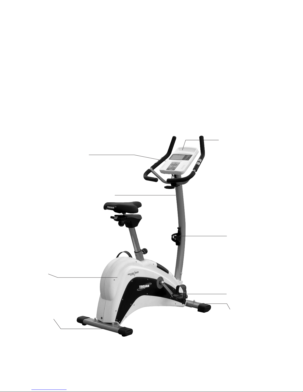
Before reading further, please review the drawing below and familiarise yourself with the parts that are labelled.
• Read this manual carefully before using the TROJAN PULSE 500 BIKE.
Rear Stabiliser
Handlebar
Upright Post
Right Pedal
Front Stabiliser
Computer
Chain Cover
Bottle Holder
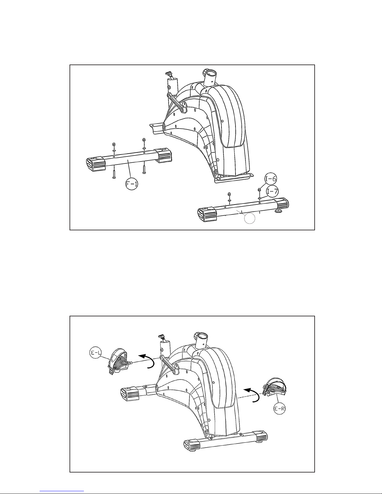
Step 1 Foot Tube Assembly
• Attach the Front Foot (F-1) and Rear Tube (G-1) to the front and back brackets of the mainframe
respectively using 4 Carriage Bolts (I-8), 4 Washers (I-7) and 4 Nuts (I-6).
Step 2 - Pedal Assembly
• Attach the Left Pedal (E-L) onto the Left Crank (D-17 L), and the Right Pedal (E-R) onto the Right Crank
(D-17 R) using a screwdriver.
Note: Screw the left pedal’s spindle anti-clockwise and the right pedal’s spindle clockwise to tighten
(reverse this procedure to loosen). Use a wrench (or screwdriver) to tighten the two spindles properly.
1064M-5
G-1
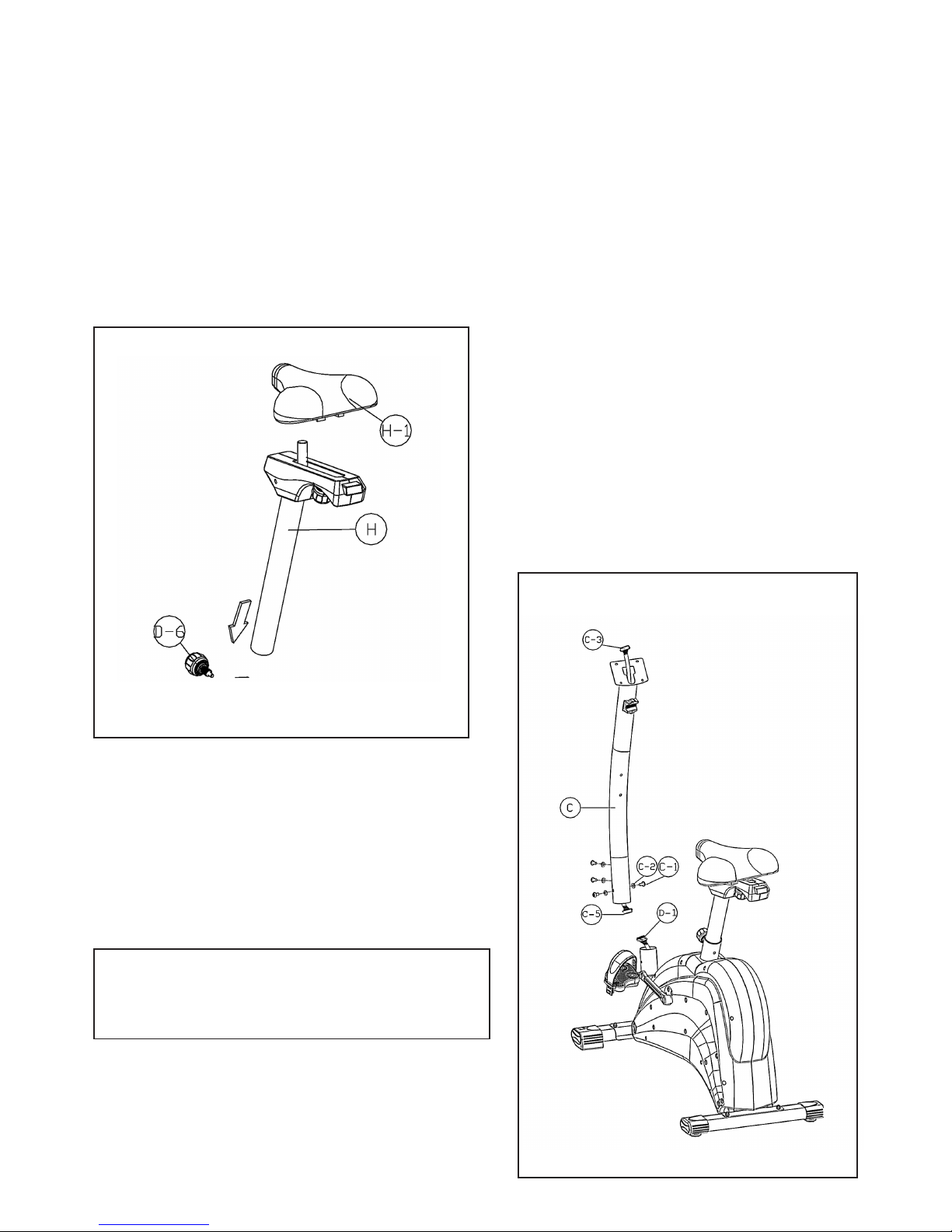
Step 3 - Seat Tube Assembly
• Unscrew the Height-adjusting Spring Knob (D-6) a little bit. Then pull the cap outward, the spindle of the
Spring Knob (D-6) will be withdrawn from the reception tube. Insert the Seat Post (H) into the Reception
Tube of the mainframe, through the Plastic Sleeve, which is pre-inserted into the Reception Tube. Tighten the
Spring Knob (D-6) when the Seat Post (H) is in position.
Note: If you cannot insert the Seat Post (H) into the Reception Tube of the mainframe after you have pulled
out the cap, please unscrew the Spring Knob (D-6) a little more until it allows the Seat Post to slide in.
• Attach the Seat (H-1) to the Seat Post (H)
1064M-6
Step 4 - Handlebar Post Assembly
• Connect the Upper Computer Cable (C5) to the Lower
Computer Cable (D-1). Now insert the
Handlebar Post (C) into the Mainframe, securing it with
4 Screws (C-1) and 4 Curved Washers (C-2).
CAUTION:
Ensure that cables are not damaged during
assembly or when tightening screws
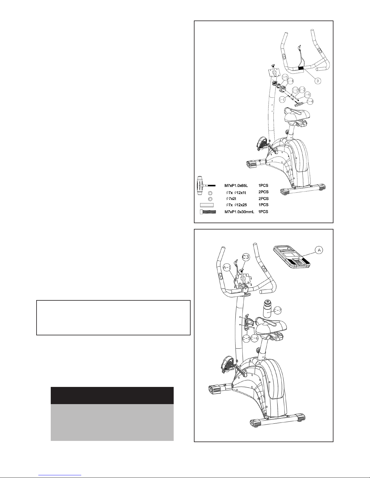
Step 5-Handlebar post Assembly
• Place Handlebar (B) on the Handlebar base, and position the Metal Cover (I-5) on the top of Handlebar (B).
• Secure the Handlebar (B) and Metal Cover (I-5) with
a Screw (I-9), Spring Washer (I-2), and Flat Washer (I-1).
Please ensure it is securely tightened.
• Place the Front Cover (C-4) on the Handlebar (B) and
insert T-shape Knob (I-4) into the Metal Cover (C-4) and
secure with Spring Washer (I-2), Flat washer (I-1) and
Bushing (I-3). Please ensure it is securely tightened.
Step 6 - Handlebar Post
Assembly
• Connect the Upper Computer Cable (C3) to the
back of the Computer (A)
• Attach the Computer (A) to the plate on top of
the Handlebar Pole with 4 Screws (A-1).
CAUTION:
Ensure that cables are not damaged during
assembly or when tightening screws
• Plug the Hand-Pulse wire (for measuring your pulse
rate) in the socket on the back of the Computer (A).
• Fasten the Bottle Cage (C-5) to the Handlebar Post
with 2 Cone Cross Screws (C-6), and insert Water
Bottle (C-7)
Recheck
all bolts and nuts are
tightened securely
before using the machine
1064M-7
 Loading...