

Trojan POWER VIBE 255 Care Instructions And Assembly Manual
in your own space / in your own time
POWER VIBE 255
VIBRATION TRAINER
CARE INSTRUCTIONS AND ASSEMBLY MANUAL
CAUTION
READ ALL PRECAUTIONS AND
INSTRUCTIONS IN THIS MANUAL
BEFORE USING THIS EQUIPMENT
KEEP THIS MANUAL FOR
FUTURE REFERENCE
CALL
08-93015557
www.trojanfitness.com.au

INDEX
SAFETY INSTRUCTION 3
HARDWARE LIST 4
ASSEMBLY STEP 5
COMPUTER FUNCTION 7
FITNESS TIPS AND TECHNIQUES 8
CONDITIONING GUIDELINES 9
WARM-UP AND COOL-DOWN 10
EXERCISE PROGRAM 11
PART LIST 15
EXPLODED DRAWING 16
TROJAN 1 YEAR LIMITED WARRANTY 17
TROJAN REPAIRS PROCEDURE 18
PROOF OF PURCHASE 19

10111-AU
page
3
SAFETY INSTRUCTION
WARNING :
To reduce the risk of serious injury, read the following safety instructions before using the TROJAN POWER VIBE 255.
I. Use the TROJAN POWER VIBE 255 only on a level surface.
2. Keep children and pets away from this equipment at all times.
3. The TROJAN POWERVIBE 255 should not be used by persons weighing more than 100kgs.
4. The TROJAN POWERVIBE 255 should be used by only one person at a time.
5. Be careful to maintain your balance while using, mounting, dismounting, folding, unfolding or assembling the
TROJAN POWERVIBE 255. Loss of balance may result in a fall and serious bodily injury.
6. Use the TROJAN POWERVIBE 255 only as described in the manual.
7. Before using this equipment to exercise, always do stretching exercises to properly warm up.
8. Always make sure all bolts and nuts are tightened prior to each use.
WARNING
Before starting any exercise or conditioning program you should consult with your personal physician to see if you
require a complete physical exam.This is especially important if you are over the age of 35, have never exercised before,
are pregnant, or suffer from any illness.
page
4
10111-AU
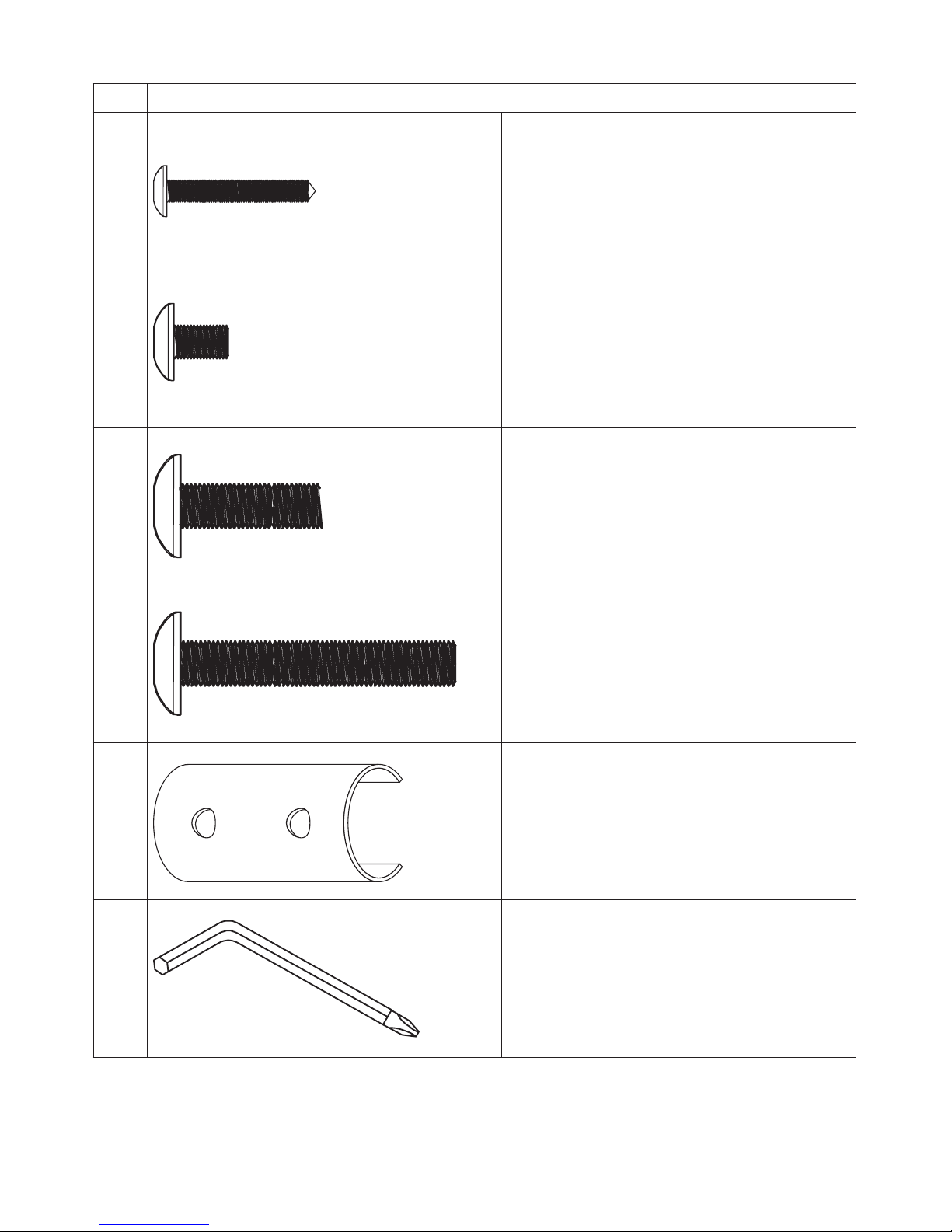
HARDWARE LIST
No. Description
No.27 Screw (M4 x l6mm) x 2pcs
No.38
Bolt (M6 x 8mm) x 4pcs
No.46
Bolt (M8 x l5mm) x 3pcs
No.37
Bolt (M8 x 50mm) x 2pcs
No.08
Reinforcing x 1pc
Tool
Allen Wrench x 1pc
NOTE :
The described parts are all you need to assemble this machine.
Before starting assembly, please check the hardware packing to make sure they are included.
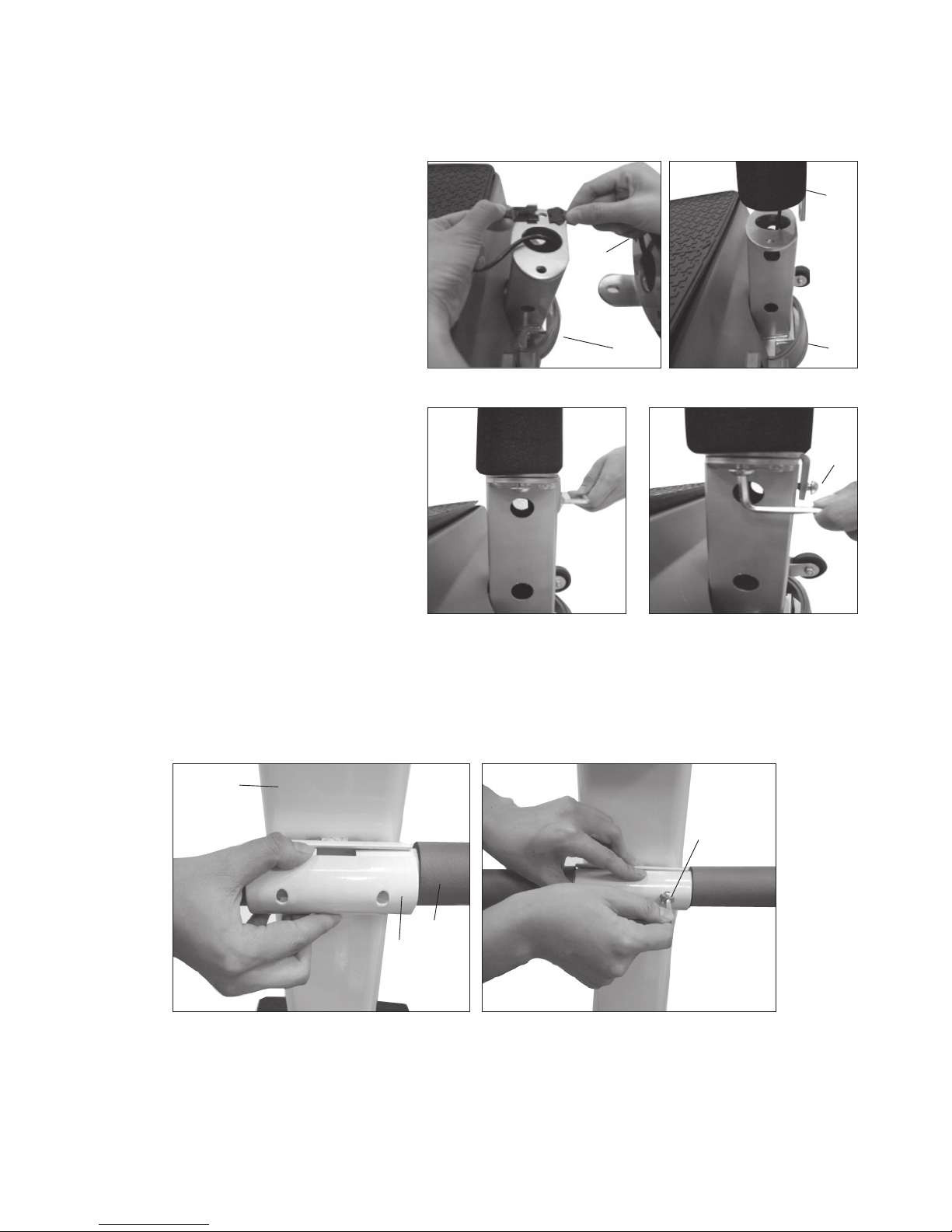
Fig. 1 Fig. 2
Fig. 3 Fig. 4
Fig. 5 Fig. 6
10111-AU
page
5
ASSEMBLY STEP
STEP 01 : ASSEMBLY FOR MAIN FRAME
Refer to drawing on page 17
• Place the Main Plate (32) on a level fl at
surface.
• Pull out the Cable of the Main Plate (32)
and connect it with the Cable from the Post
(9). As in Fig. I
• Attach the Post (9) to the Main Plate (32).
As in Fig.2
• Secure Post (9) with three M8 x I 5mm
Bolts (46) As in Fig.3 & 4
STEP 02 : ASSEMBLY FOR HANDLE BAR
• Attach the Handle Bar (6) to the Post (9), secure it with the Reinforcement Plate (8) and two M8 x 50mm Bolts (37).
As in Fig.5 & 6
• Unpack the carton, and using the parts list check that all components are present.
• Don’t dispose of packing material until assembly has been completed.
• An Allen Wrench is included for the assembly process.
32
9
9
32
46
9
6
8
37
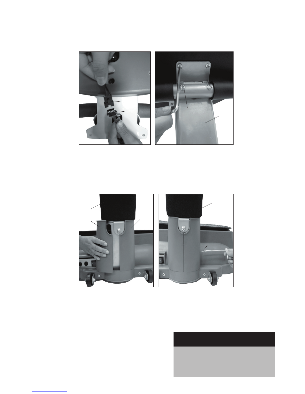
Fig. 7 Fig. 8
5
10
38
9
Fig. 9 Fig. 10
14
15
9
9
27
page
6
10111-AU
ASSEMBLY STEP
Recheck
all bolts and nuts are
tightened securely
before use the machine
STEP 03 : CONNECTING THE COMPUTER
• Connect the Computer Cables (10). As in Fig.7
• Attach the Computer to the Post (9), and secure it with four M6 x 8mm Bolts (38). As in Fig.8
STEP 04: ASSEMBLING THE FRAME COVER
• Attach the Left and Right Cover (14, 15) to the Post (9). As in Fig.9
• Secure it with two M4 x I 6mm Screws (27). As in Fig. 10
Note :
To protect the fl oor or carpet from damage, place a
mat under the POWER VIBE 255
 Loading...