

Trojan POWER STACK 500, PERFORMA 300 Instructions & Assembly
HOME GYM CARE INSTRUCTIONS
AND ASSEMBLY MANUAL
TROJAN
MY SPACE MY TIME
®
#
1
HOME
FITNESS
SO
UTH AFRI
CA’
S
SI
N
CE
1981
CAUTION
READ ALL PRECAUTIONS AND
INSTRUCTIONS IN THIS MANUAL
BEFORE USING THIS EQUIPMENT
KEEP THIS MANUAL FOR
FUTURE REFERENCE
1 YEAR
warranty
CALL
0861 876526
0861 TROJAN
POWER STACK 500
HOME GYM
1574

1. SAFETY INSTRUCTIONS 3
2. PRE ASSEMBLY CHECK LIST 4
3. PARTS LIST 5
4. HARDWARE LIST 7
5. ASSEMBLY STEPS 9
6. FITNESS TIPS AND TECHNIQUES 18
7. CONDITIONING GUIDELINES 19
8. WARM-UP AND COOL-DOWN 20
9. EXERCISE PROGRAM 21
10. FREQUENTLY ASKED QUESTIONS 25
11. EXPLODED DRAWING 26
12. TROJAN 1 YEAR LIMITED WARRANTY 27
13. TROJAN REPAIRS PROCEDURE 29
INDEX PAGE

1574-3
1. SAFETY INSTRUCTIONS
WARNING :
To reduce the risk of serious injury, read the following safety instruction before using the TROJAN POWER
STACK 500.
1. Use the TROJAN POWER STACK 500 only on a level surface.
2. Keep children and pets away from this equipment at all times.
3. The TROJAN POWER STACK 500 is able to handle a max user weight (120kg) and stack weight (68kg)
4. The TROJAN POWER STACK 500 should be used by only one person at a time.
5. Be careful to maintain your balance while using, mounting, dismounting, folding, unfolding or assembling the TROJAN
POWER STACK 500, loss of balance may result in a fall and serious bodily injury.
6. Use the TROJAN POWER STACK 500 only as described in the manual.
7. Do not attempt to adjust the back rest while you are on the TROJAN POWER STACK 500.
8. Before using this equipment to exercise, always do stretching exercises to warm up properly.
9. Always make sure all bolts and nuts are tightened prior to each use.
WARNING
Before starting any exercise or conditioning program you should consult with your personal physician to see if you
require a complete physical exam. This is especially important if you are over the age of 35, have never exercised before,
are pregnant, or suffer from any illness.
1574-4
Thank you for choosing the TROJAN POWER STACK 500 We take great pride in producing this quality product and
hope it will provide many hours of quality exercise to make you feel better, look better and enjoy life to its fullest.
Yes, it’s a proven fact that a regular exercise program can improve your physical and mental health. Too often, our busy
lifestyles limit our time and opportunity to exercise. The TROJAN POWER STACK 500 provides a convenient and simple
method to begin your assault on getting your body in shape and achieving a healthier lifestyle.
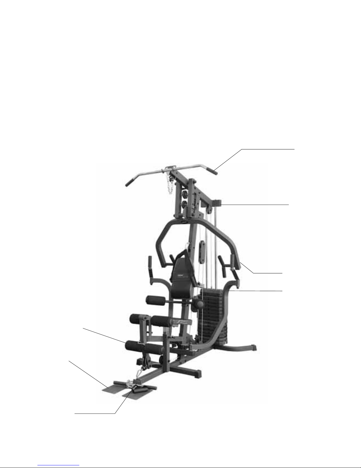
Before reading further, please review the drawing below and familiarize yourself with the parts that are labeled.
• Read this manual carefully before using the TROJAN POWER STACK 500
Leg Extension
Frame
Press Arm
Butterfly Arm
Lat Bar
Foot Plate
Spport Frame
Motif Plate
2. PRE ASSEMBLY CHECK LIST
1574-5
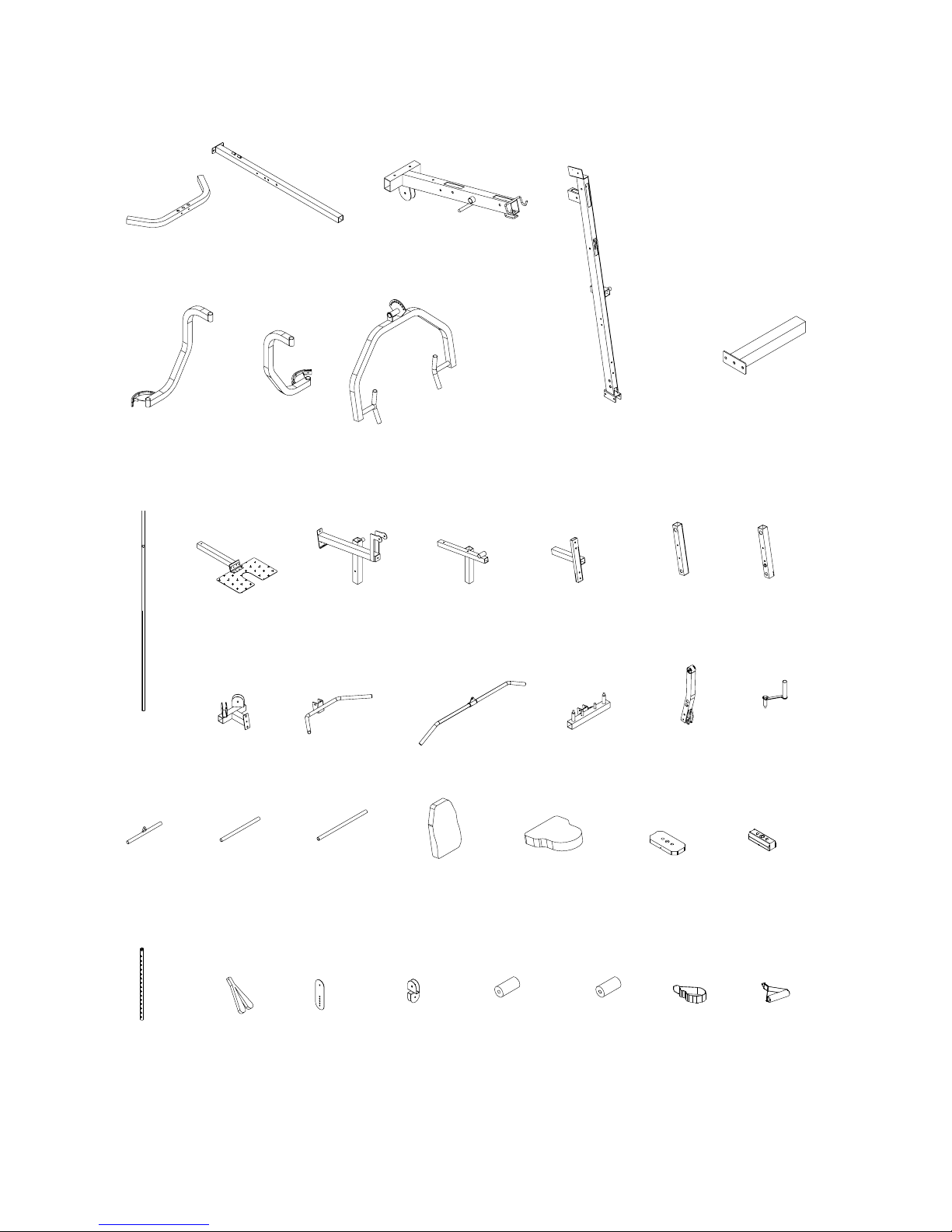
3. PARTS LIST
(23L)LONG
FOAM ROD
1PC
(32B)FOAM
ROLL 2PCS
(1)REAR BASE
FRAME 1PC
(2)MAIN BASE
FRAME 1PC
(3)TOP FRAME
1PC
(4)LEFT PRESS
FRAME 1PC
(5)RIGHT
PRESS FRAME
1PC
(6)PRESS ARM
1PC
(7)FRONT
UPRIGHT 1PC
(8)BASE FRAME
2PCS
(9)CHROME
TUBE 2PCS
(12)SEAT
FRAME 1PC
(11)SEAT
SUPPORT
FRAME 1PC
(10)FOOT PLATE
1PC
(13)BACK REST
SUPPORT 1PC
(14)RIGHT
CONNECT
FRAME 1PC
(15)LEFT
CONNECT
FRAME 1PC
(16)BRACKET
SUPPORT
1PC
(17)HAND BAR
1PC
(18)LAT BAR
1PC
(19)BUTTERFLY
MOUNT 1PC
(20)LEG
EXTENSION
1PC
(21)HAND TUBE
2PCS
(27)TOP
WEIGHT 1PC
(26)WEIGHT
PLATE 14PCS
(25)SEAT
CUSHION 1PC
(24)BACKREST
CUSHION 1PC
(23S)SHORT
FOAM ROD
1PC
(22)CURL BAR
1PC
(34)HANDLE
1PC
(32A)BIG FOAM
ROLL 4PCS
(31)PULLEY
HOUSING
1PC
(30)STEEL
PLATE 2PCS
(29)AB
STRAP
1PC
(28)WEIGHT
SELECTION
ROD 1PC
(33)ANKLE
STRAP 1PC

1574-6
PARTS LIST
(100)SINGLE
PULLEY
BRACKET 1PC
(101)LOCK
HOOK 1PC
(102)3/8" PLASTIC
DOME CAP 8PCS
(103)1/2" PLASTIC
DOME CAP 2PCS
(104)5/8" PLASTIC
DOME CAP 4PCS
(105)PIN 1PC
(94)TAPER
END PLUG 1PC
(36)CONNECT
PLATE 1PC
(37)CHAIN 1PC
(38)LONG CHAIN
1PC
(39)BIG PIVOT
SHAFT 1PC
(40)PIVOT SHAFT
1PC
(41)BLACK BALL
PIN 1PC
(42)PULLEY HOOK
1PC
(43)LONG POP PIN
1PC
(44)POP PIN
2PCS
(49)50X75mm
SQUARE PLUG
4PCS
(48)ROUND
DONUT 2PCS
(47)SQUARE END
CAP 4PCS
(46)PULLEY
17PCS
(45)CHAIN HOOK
5PCS
(54)HAND GRIP
4PCS
(53)SQUARE
BUMPER 1PC
(52)32mm ROUND
END PLUG 8 PCS
(51)45X45mm
SQUARE END
PLUG 1PC
(50)50X50m
m
SQUARE EN
D
PLUG 11PC
S
(59)STEEL
BUSHING 2PCS
(58)LONG HAND
GRIP 2PCS
(57)SHORT FOAM
GRIP 4PCS
(56)LONG FOA
M
GRIP 2PCS
(55)SMALL HAND
GRIP 2PCS
(65)25X50mm
SQUARE PLUG
2PCS
(64)LITTLE
COVER 2PCS
(62)COPPER
BUSHING 10
P
(61)LITTLE OIL
BUSHING 6PCS
(60)ROUND CAP
6PCS
(71)BUTTERFLY
CABLE 1PC
(69)LOWER
CABLE 1PC
(68)LITTLE
BUSHING 2P
C
(67)MIDDLE
BUSHING 11PCS
(66)38X38mm
SQUARE END
PLUG 2PCS
(63)BIG BUSHING
4PCS
(70)UPPER CABLE
1PC
PLASTIC BUSHING
PC
5)
NOTE :
The described parts are all you need to assemble this machine.
Before starting assembly, please check the hardware packing to make sure they are included.
1574-7
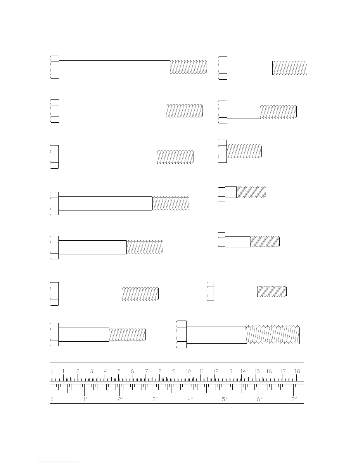
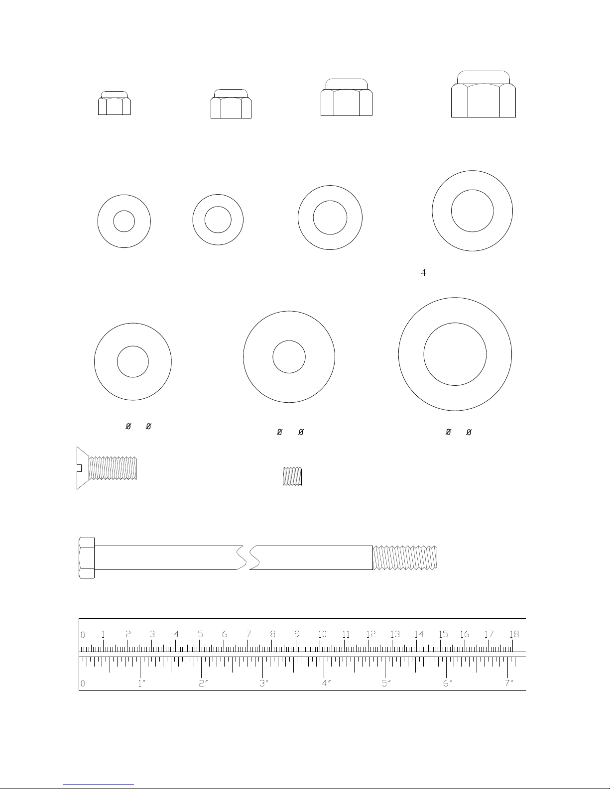
(97)M8X30mm HEX BOLT 2PCS
(78)3/8"x2-3/8" HEX BOLT 2PCS
(95)3/8"x4" HEX BOLT 1PC
(81)M8X40mm HEX BOLT 2PCS
(79)M8X53mm HEX BOLT 2PCS
mm
(80)3/8"x2" HEX BOLT 8PCS
(82)3/8"x1" HEX BOLT 5PCS
(74)3/8"x3-3/4" HEX BOLT 2PCS
(72)3/8"x4-1/4" HEX BOLT 1PC
(75)3/8"x3" HEX BOLT 8PCS
(76)3/8"x2-7/8" HEX BOLT 2PCS
(77)3/8"x2-1/2" HEX BOLT 5PCS
(73)3/8"x3-7/8" HEX BOLT 1PC
(92)1/2"x3-1/4" HEX BOLT 2PCS
4. HARDWARE LIST
1574-8
HARDWARE LIST
(98)M8 LOCKNUT
2PCS
(99)8mm WASHER
8PCS
(106)WASHER
(T3.0X 13X 32)
1PC
mm
(89) WASHER
(T3.0X 47X 26)
1PC
(90)BIG WASHER
(T3.0X 38X 13.5)
4PCS
(93)3/8"x8-3/4" HEX BOLT 2PCS
(96)M10x25mmSCREW 1PC
(87)1/2" WASHER
4PCS
(84)1/2" LOCKNUT
6PCS
(83)3/8" LOCKNUT
32PCS
(86)3/8" WASHER
67PCS
(88)5/8" WASHER
PCS
(91)M6x8mmSCREW 2PCS
(85)5/8" LOCKNUT
4PCS
1574-9
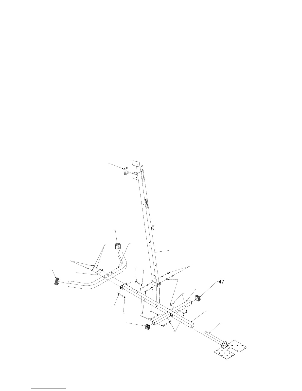
STEP 1
• Push Square End Cap (47) onto ends of Rear Base Frame (1) and Base Frame (8). Attach Connect Plate (36) and
Rear Base Frame (1) to Main Base Frame (2) using 2- 3/8”X3” hex bolts (75) 4-3/8” Washers (86) 2-3/8” Locknuts
(83).
• Plug 50x75mm Square Plug (49) onto Front Upright (7). Insert Foot Plate (10) to Main Base Frame (2).
• Attach Two Base Frame (8) to Main Base Frame (2),
• Attach Front Upright (7) to Main Base Frame (2) using 4- 3/8”X3” Hex Bolts (75) 8-3/8” Washers (86) 4-3/8”
Locknuts (83).
5. ASSEMBLY STEPS
47
83
86
47
1
2
10
7
49
83
86
36
47
75
86
75
86
83
86
75
86
8
1574-10
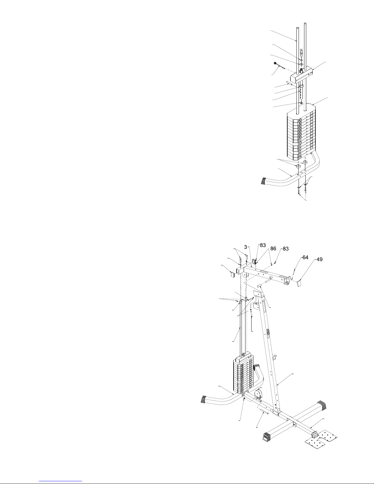
STEP 2
• Install two Chrome Tubes (9) into holes of Rear Base Frame (1) using
2-3/8”X1” Hex Bolts (82) 2-3/8” Washers (86).
• Slide two Round Donuts (48) down Chrome Tubes (9).
• Slide 14 pcs Weight Plates (26) and Weight Selection Rod (28) down
Chrome T ubes (9)
• Slide Top Weight (27) down.
• Attach Plastic Bushing (35) to Weight Selection Rod (28) with Pin (105).
• Place T3.0xø47xø26 Washer (89) and T3.0xø13xø32 Washer (106) onto
the hole of Top Weight (27).
• Attach Nut end of Top Cable to Weight Selection Rod (28).
• Install black Ball Pin (41) to Weight Selection Rod (28) as shown.
STEP 3
• Attach two Steel Bushings (59) to top of Chrome Tubes (9)
using 2- M6x8mm Screws (91)
• Attach Top Frame (3) to top of Chrome Tube (9) using
2-3/8”X1” Hex Bolts (82) 2-3/8” Washers (86).
• Attach Top Frame (3) to Front Upright (7) using
1-3/8”X3-3/4” hex bolt (74) 1-3/8”X2-7/8” Hex Bolt (76)
4-3/8” Washers (86) 2-3/8” Locknuts (83).
• Attach Single Pulley Bracket (100) to Main Base Frame (2)
using 1-3/8”X4” Hex Bolt (95) 1-3/8” Locknut (83).
• Push two Long Handle Grips (58) onto each end of Shaft of
Top Frame (3).
• Push two Little Covers (64) onto each end of Hook of Top
Frame (3).
ASSEMBLY STEPS
82
86
26
27
1
35
41
105
48
9
89
94
28
106
58
7
82
86
74
86
76
2
49
95
83
100
1
59
91
9
 Loading...