

Trojan POWER CAGE 400 Care Instructions And Assembly Manual

POWER CAGE 400
HOME GYM
HOME GYM CARE INSTRUCTIONS
AND ASSEMBLY MANUAL
TROJAN
MY SPACE MY TIME
®
#
1
HOME
FITNESS
SO
UTH AFRI
CA’
S
SI
N
CE
1981
CAUTION
READ ALL PRECAUTIONS AND
INSTRUCTIONS IN THIS MANUAL
BEFORE USING THIS EQUIPMENT
KEEP THIS MANUAL FOR
FUTURE REFERENCE
1 YEAR
warranty
CALL
0861 876526
0861 TROJAN
769

INDEX PAGE
1. SAFETY INSTRUCTIONS 3
2. PRE ASSEMBLY CHECK LIST 4
3. HARDWARE LIST 5
4. ASSEMBLY STEPS (CAGE) 7
5. ASSEMBLY STEPS (BENCH) 12
6. FITNESS TIPS AND TECHNIQUES 14
7. CONDITIONING GUIDELINES 15
8. WARM-UP AND COOL-DOWN 16
9. EXERCISE PROGRAM 17
10. FREQUENTLY ASKED QUESTIONS 25
11. PARTS LIST 26
12. EXPLODED DRAWING 31
13. TROJAN 1 YEAR LIMITED WARRANTY 32
14. TROJAN REPAIRS PROCEDURE 34

769-3
1. SAFETY INSTRUCTIONS
WARNING :
To reduce the risk of serious injury, read the following safety instruction before using the TROJAN POWER CAGE 400.
1. Use the TROJAN POWER CAGE 400 only on a level surface.
2. Keep children and pets away from this equipment at all times.
3. The TROJAN POWER CAGE 400 is able to handle a total load weight of 200kgs (user & weights)
Note: The lat pull down bar is limited to 70kgs
4. The TROJAN POWER CAGE 400 should be used by only one person at a time.
5. Be careful to maintain your balance while using, mounting, dismounting, folding, unfolding or assembling the TROJAN
POWER CAGE 400, loss of balance may result in a fall and serious bodily injury.
6. Use the TROJAN POWER CAGE 400 only as described in the manual.
7. Do not attempt to adjust the back rest cushion while you are on the TROJAN POWER CAGE 400.
8. Before using this equipment to exercise, always do stretching exercises to warm up properly.
9. Always make sure all bolts and nuts are tightened prior to each use.
WARNING
Before starting any exercise or conditioning program you should consult with your personal physician to see if you
require a complete physical exam. This is especially important if you are over the age of 35, have never exercised before,
are pregnant, or suffer from any illness.
769-4
Thank you for choosing the TROJAN POWER CAGE 400. We take great pride in producing this quality product and
hope it will provide many hours of quality exercise to make you feel better, look better and enjoy life to its fullest.
Yes, it’s a proven fact that a regular exercise program can improve your physical and mental health. Too often, our busy
lifestyles limit our time and opportunity to exercise. The TROJAN POWER CAGE 400 provides a convenient and simple
method to begin your assault on getting your body in shape and achieving a healthier lifestyle.
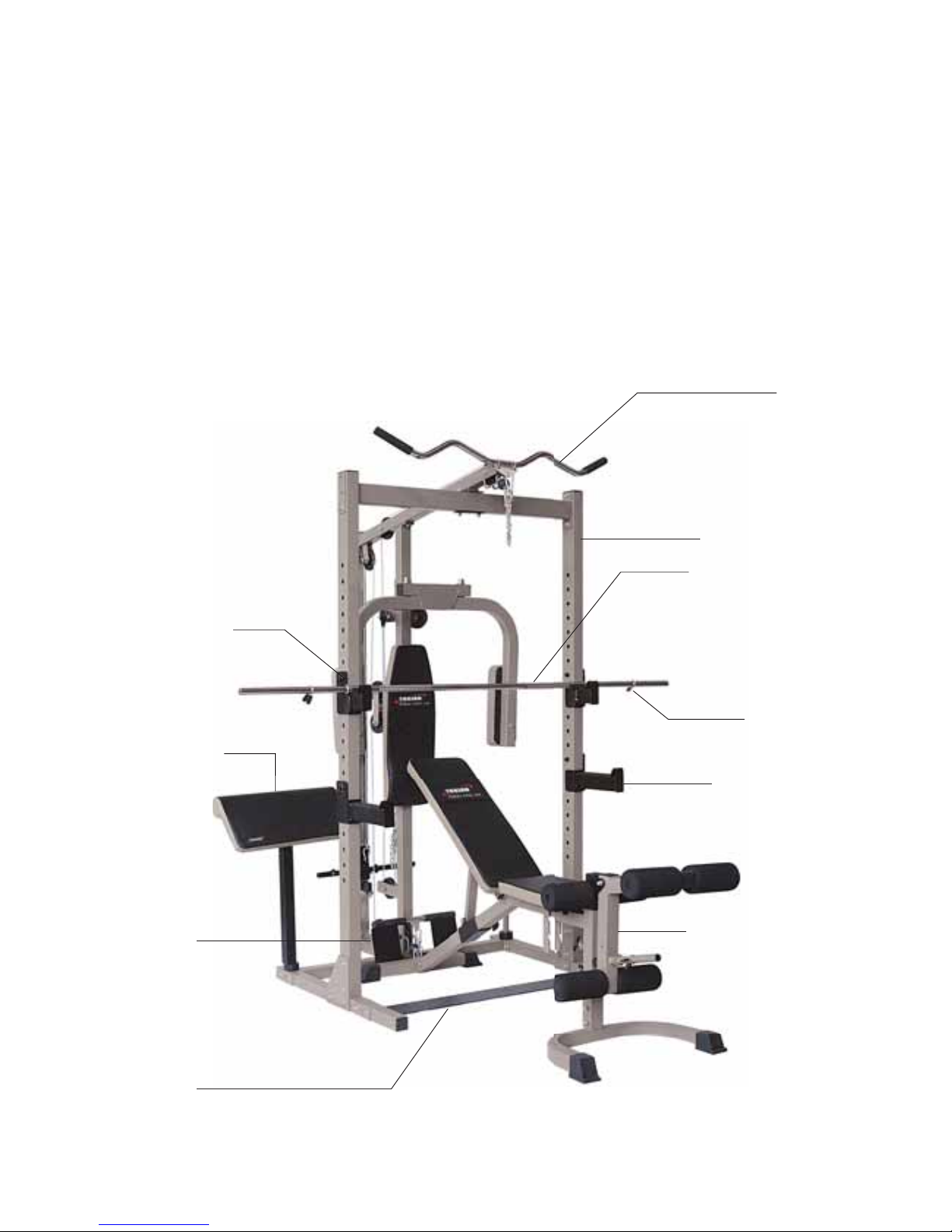
Before reading further, please review the drawing below and familiarize yourself with the parts that are labeled.
• Read this manual carefully before using the TROJAN POWER CAGE 400.
Arm Curl Pad
Leg Extension Frame
Quick Clip
Little Barbell Crutch
Assembly (Left)
Lat Bar
Foot Plate
Left Big Barbell
Crutch Assembly
Front Spport Frame
Motif Plate
Barbell Crtch Frame
2. PRE ASSEMBLY CHECK LIST
769-5
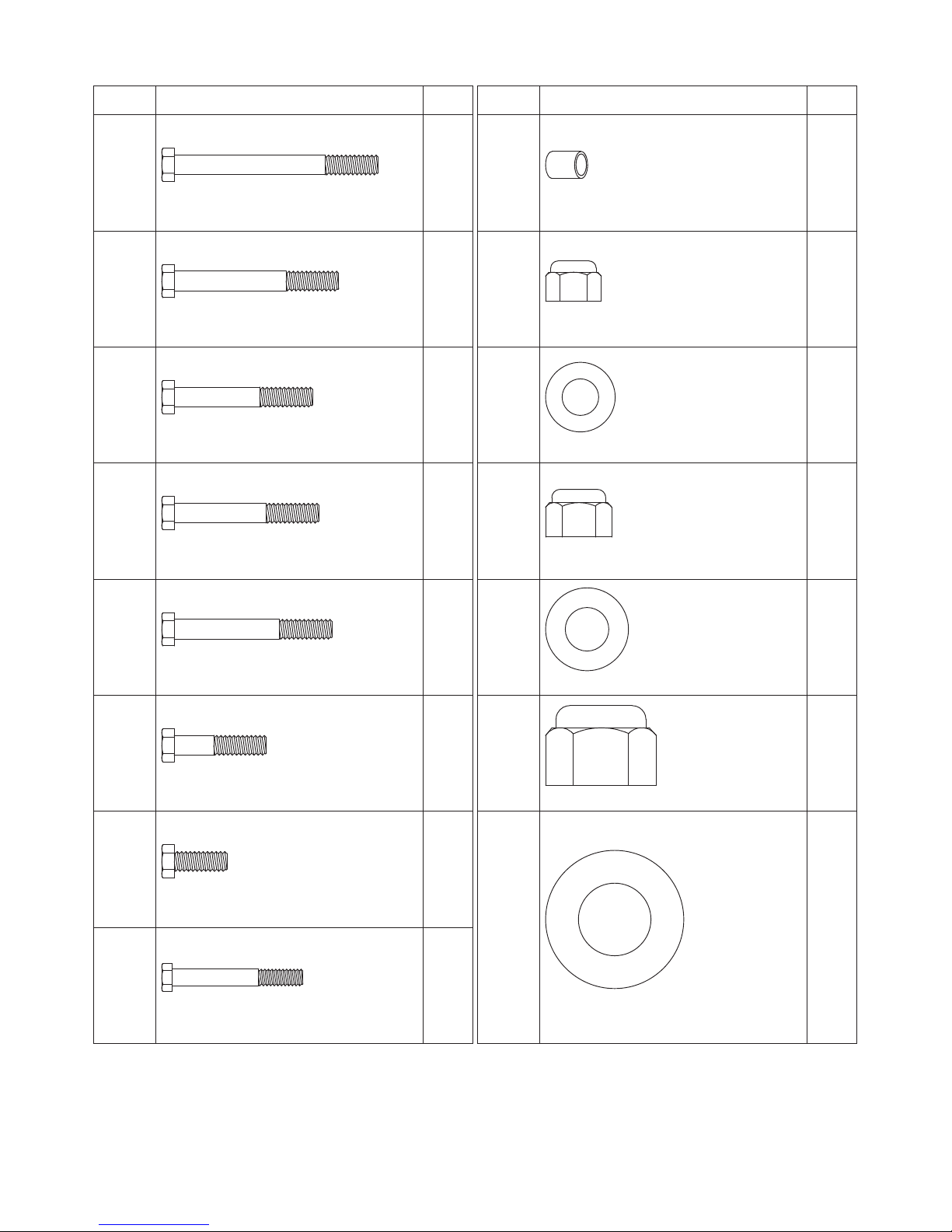
3. HARDWARE LIST (CAGE)
NOTE :
The described parts are all you need to assemble this machine.
Before starting assembly, please check the hardware packing to make sure they are included.
No. Discription Q’ty
44
Hex Bolt (3/8” x 3-7/8”)
2
45
Hex Bolt (3/8” x 3-1/8”)
2
46
Hex Bolt (3/8” x 3”)
22
47
Hex Bolt (3/8” x 2-3/4”)
2
48
Hex Bolt (3/8” x 2-5/8”)
4
49
Hex Bolt (3/8” x l-3/4”)
7
50
Hex Bolt (3/8” x l”)
6
51
Hex Bolt (M5x 63mm)
8
No. Discription Q’ty
52
Bushing (14.5mm)
8
53
Locknut (M8)
2
54
Washer (8mm)
10
55
Locknut (3/8”)
41
56
Washer (3/8”)
86
57
Locknut (5/8”)
2
58
Washer (5/8”)
2
769-6
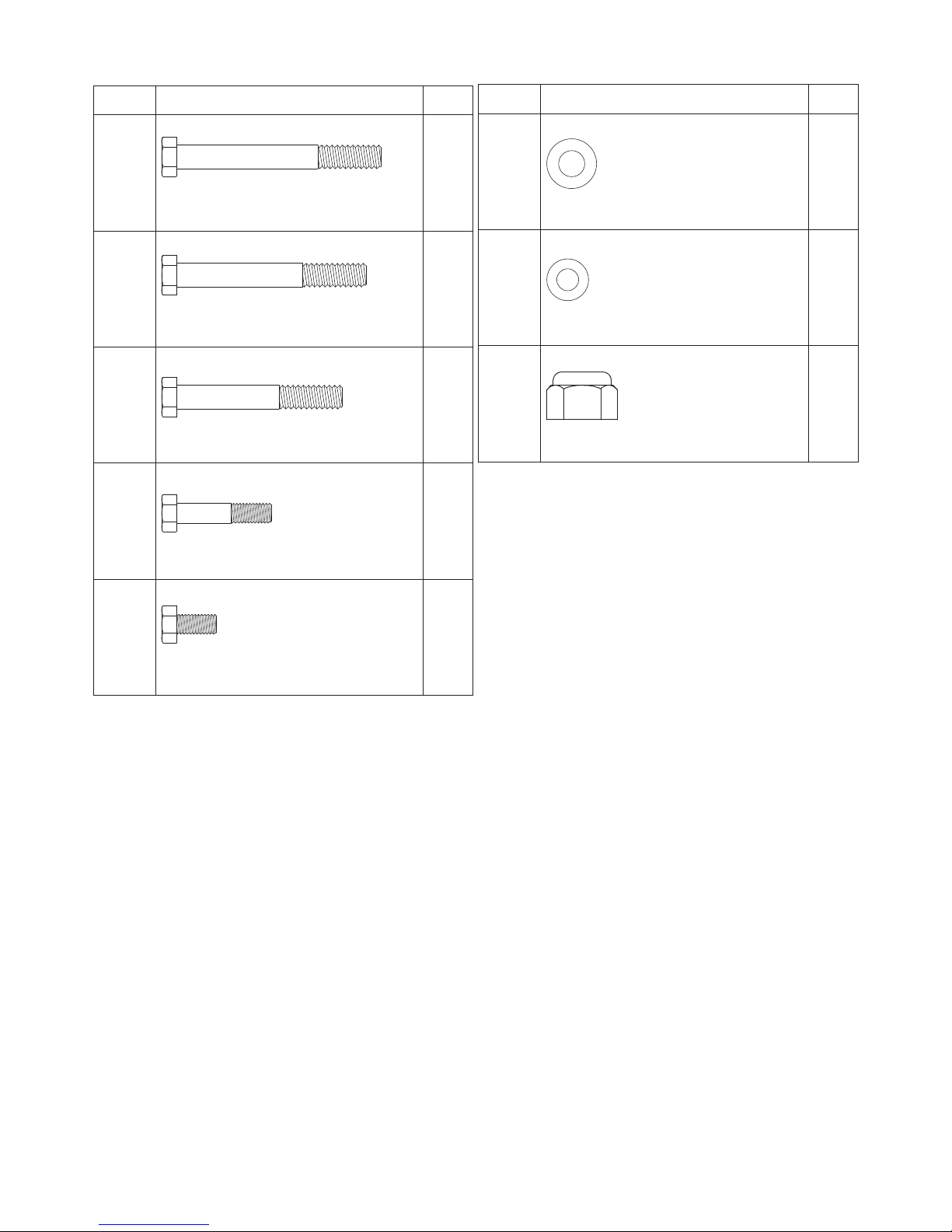
HARDWARE LIST (BENCH)
NOTE :
The described parts are all you need to assemble this machine.
Before starting assembly, please check the hardware packing to make sure they are included.
No. Discription Q’ty
29
Hex Bolt (3/8” x 3-1/8” )
1
30
Hex Bolt (3/8” x 3”)
1
31
Hex Bolt (3/8” x 2-5/8”)
3
32
Hex Bolt (M8 x 38mm)
8
33
Hex Bolt (M8 x 16mm)
2
No. Discription Q’ty
35
Washer (ø3/8” )
10
36
Washer (48mm)
10
34
Locknut (3/8” )
5
769-7
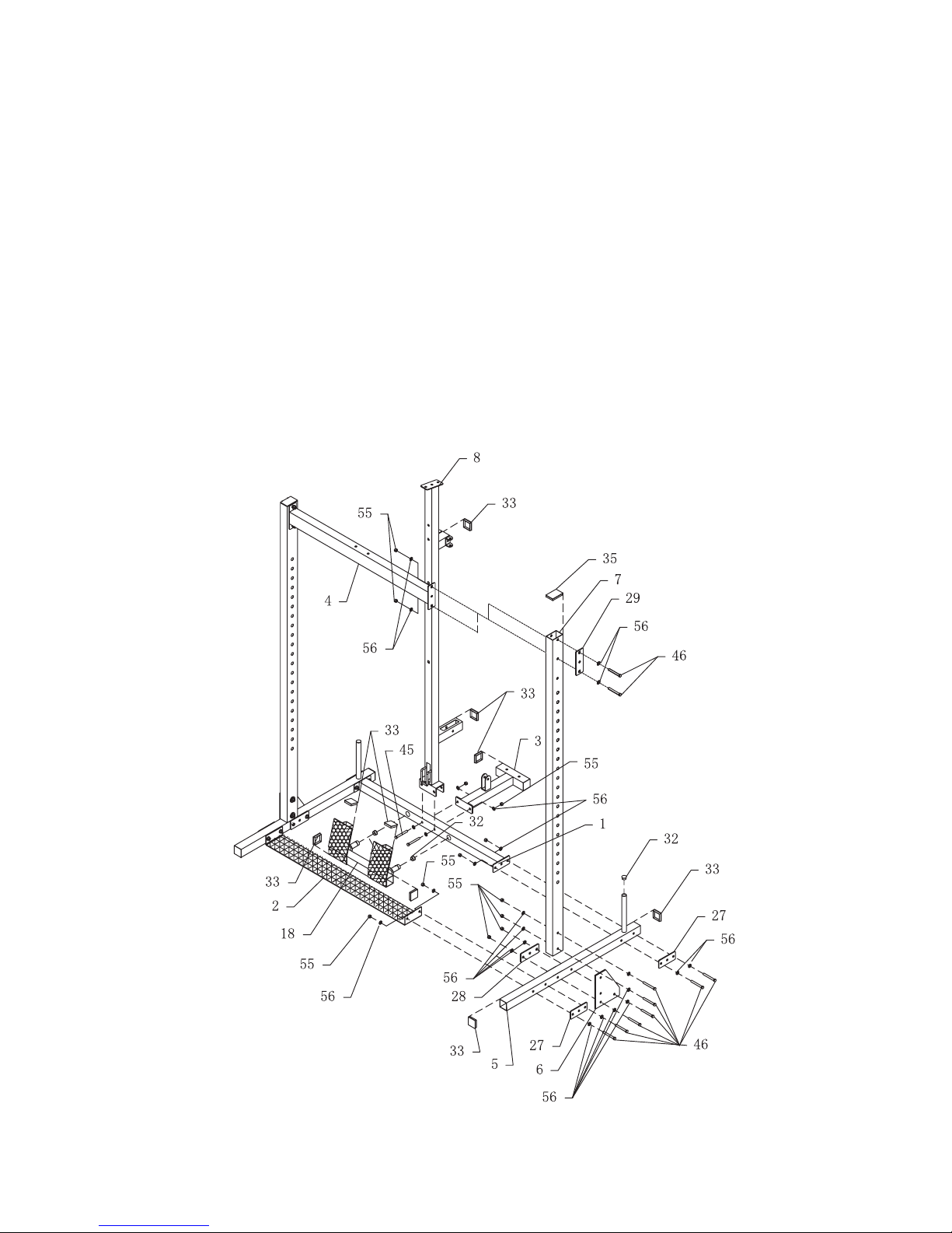
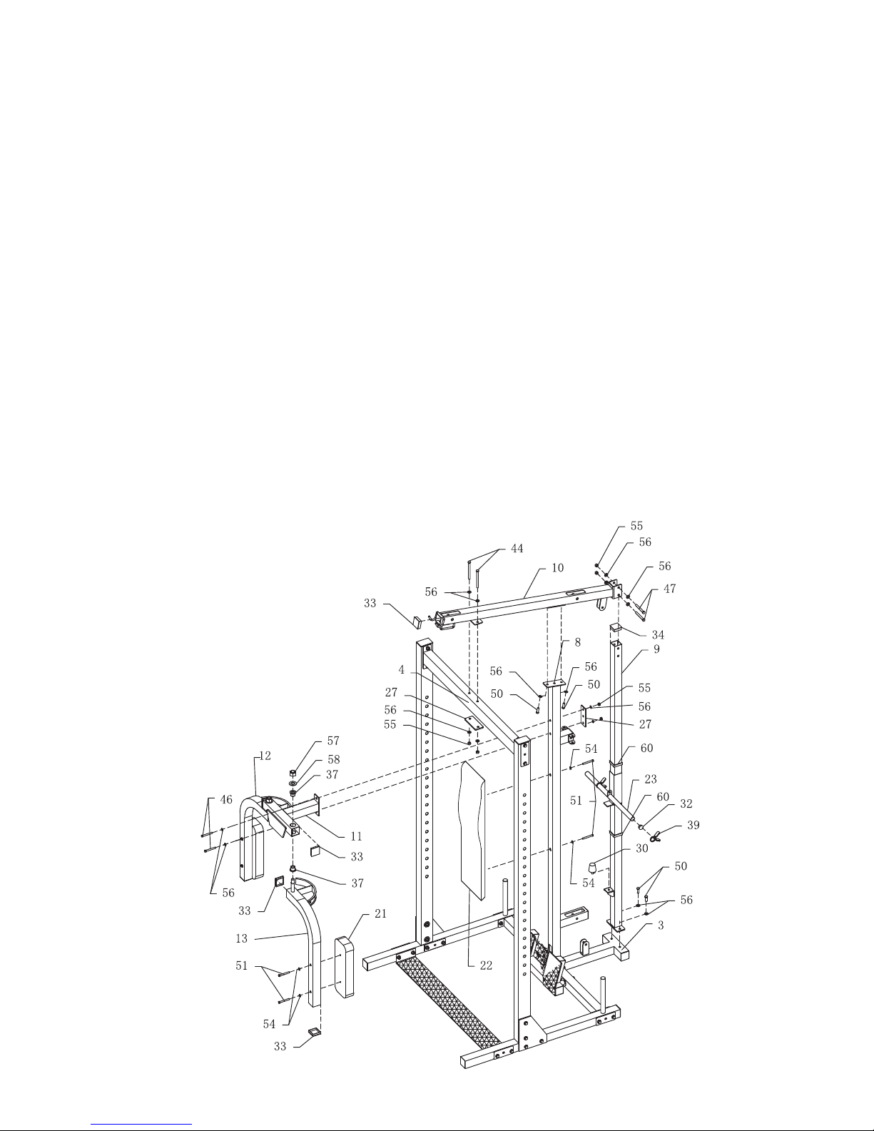
STEP 01
• Push (50 x 50mm) Square End Plug (33) into both ends of Base Frame (5), push (50 x 75mm) Square End Plug (35)
into top of Front Support Frame (7).
• Connect two Base Frames (5) using Back Cross Frame (1), Motif Plate (2) with four Reinforcement Patches (27),
(3/8” x 3” ) Hex Bolts (46), (3/8”) Washers (56) and (3/8”) Locknuts (55) as shown.
• Attach two Front Support Frames (7) and align the holes located on the bottom of Front Support Frame (7) to top
holes of Support Plate (6) using two Reinforcement Patches (28), (3/8” x 3”) Hex Bolts (46), (3/8”) Washers (56) and
(3/8”) Locknuts (55).
• Connect two Front Support Frames (7) using Top Cross Frames (4) with two Reinforcement Patches (29), (3/8” x 3”)
Hex Bolts (46), (3/8”) Washers (56) and (3/8”) Locknuts (55) as shown.
• Push (50 x 50mm) Square End Plugs (33) into Center Vertical Frame (8) and Back Base Frame (3) as shown.
• Attach Center Vertical Frame (8) and Back Base Frame (3) to Back Cross Frame (1) using (3/8” x 3-1/8”) Hex Bolts
(45), (3/8”) Washers (56) and (3/8”) Locknuts (55) as shown.
4. ASSEMBLY STEPS (CAGE)
769-8
ASSEMBLY STEPS (CAGE)
STEP 02
• Push (45 x 45mm) Square End Plug (34) into top of Back Support Frame (9), and attach Back Support Frame (9) to
Back Base Frame (3) using (3/8”x l”) Hex Bolts (50) and (3/8”) Washers (56) and (3/8”) Locknuts (55)
• Install Rubber Bumper (30) onto Back Support Frame (9).
• Push (1”) Quick Clip (39) and (ø25) Round End Plug (32) onto Weight Plate Sleeve (23), (50 x 45mm) Square Bushing
(60) into both end of Weight Plate Sleeve (23), slide Weight Plate Sleeve (23) down Back Support Frame (9).
• Attach Back Top Cross Frame (10) to Top Cross Frame (4) using Reinforcement Plate (27), (3/8” X 3-7/8”) Hex Bolt
(44), 3/8” Washer (56) and 3/8” Locknut (55); to Center Vertical FramE (8) using (3/8” x l”) Hex Bolt (50) and (3/8”)
Washer (56); (3/8”) Locknuts (55) to Back Support Frame (9) using (3/8” x 2-3/4”) Hex Bolt (47), (3/8”) Washer (56)
and (3/8”) Locknut (55) as shown.
• Push (50 x 50mm) Square End Plugs (33) into both ends of Butterfly Extension (11).
• Attach Butterfly Extension (11) to Center Vertical Frame (8) using Reinforcement Plate (27), (3/8”x3”) Hex Bolts (46),
(3/8”) Washers (56) and (3/8”) Locknuts(55).
• Push (50 x 50mm) Square End Plug (33) into both ends of Right Butterfly Arm (12) and Left Butterfly Arm (13).
• Install Little Oil Bushing (37) to Butterfly Extension (11), attach Right Butterfly Arm (12) and Left Butterfly Arm (13) to
Butterfly Extension (11) using (5/8”) Washers (58) and (5/8”) Locknuts (57).
• Attach Backrest Cushion (22) to Center Vertical Frame (8) using (M8 x 63mm) Hex Bolt (51and 8mm) Washers (54).
• Attach Arm Pad (21) to Right Butterfly Arm (12) and Left Butterfly Arm (13) using (M8 x 63mm) Hex Bolts (51),
(8mm) Washers (54).
769-9
ASSEMBLY STEPS (CAGE)
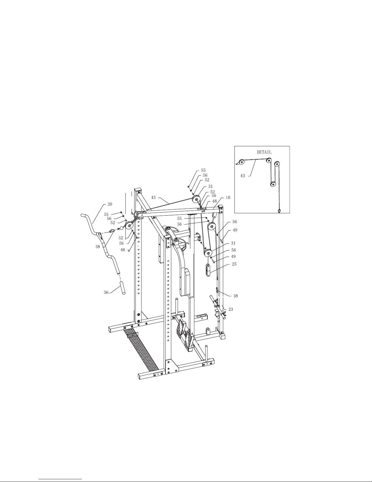
STEP 03
• Thread eye of the Upper Cable (43) through pulley housing on Back Top Cross Frame (10).
• Install Pulley (31) into pulley housing using (14.5mm) Bushing (52), (3/8” x 2-5/8”) Hex Bolts (46), (3/8”) Washers (56)
and (3/8”) Locknuts(55).
• Install a pulley into the bracket on the Back Top Cross Frame (10) using (3/8” x l-3/4”) Hex Bolts (46), (3/8”) Washers
(56) and (3/8”) Locknuts(55).
• Attach the eye of Upper Cable (43) to Weight Plate Sleeve (23) with Chain Hook (38).
• Hang Pulley (31) on the Upper Cable (43), install this pulley into Double Pulley Bracket (25) using (3/8” x l-3/4”) Hex
Bolts (46), (3/8”) Washers (56) and (3/8”) Locknuts(55).
• Push PVC Hand Grip (36) onto Lat Bar (20), attach Lat Bar (20) to end of Upper Cable (43) using Chain Hook (38).

769-10
STEP 04
• Attach two Single Pulley Bracket (26) to brackets on Center Vertical Frame (8) using (M8 x 63mm) Hex Bolt (51),
(8mm) Washer (54) and (M8) Locknut (53).
• Attach Pulley (31) into Single Pulley Bracket (31) using (3/8” x l-3/4”) Hex Bolts (46), (3/8”) Washers (56) and (3/8”)
Locknuts(55).
• Install Pulley (31) into Floating Pulley Bracket (24), and insert one end of Butterfly Cable (42) under Pulley in Floating
Pulley Bracket (24) and over Pulley in Single Pulley Bracket (31) as shown.
• Attach eye end of Butterfly Cable (42) to RIGHT Butterflyarm (12) and Left Butterflyarm (13) using (3/8” x l”) Hex
Bolts (46), (3/8”) Washers (56) and (3/8”) Locknuts(55).
• Install Rubber Doughnut (59) to weight rod on the Base Frame (5).
• Attach Little Barbell Catch Assembly (14) and Big Barbell Catch Assembly (16) to Front Support Frame (7) as shown.
ASSEMBLY STEPS (CAGE)
17
14
7
769-11
ASSEMBLY STEPS (CAGE)
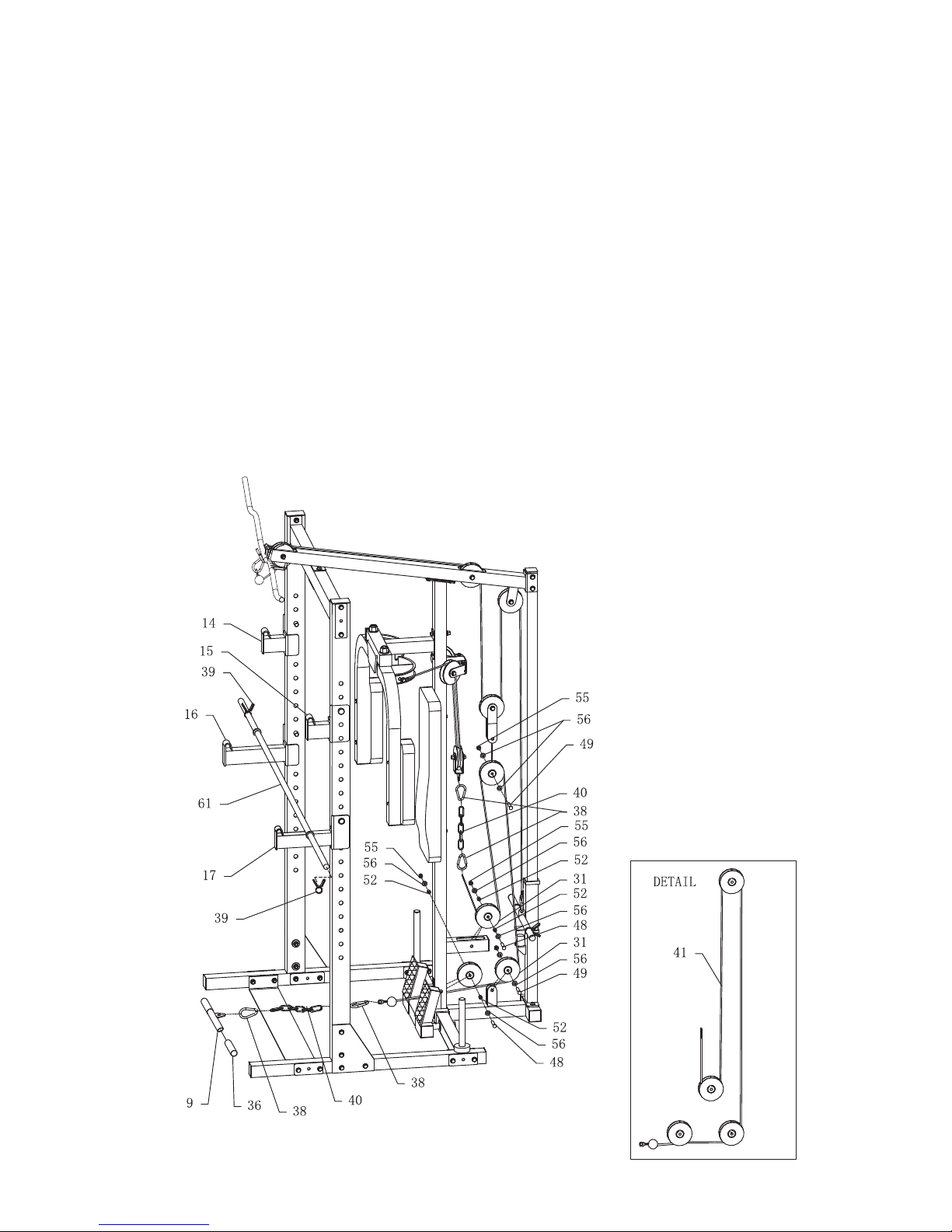
STEP 05
• Thread Lower Cable (41) through bottom pulley housing of Center Vertical Frame (8) and the other back pulley house
as shown.
• Install Pulley (31) into pulley housing using (3/8” x 25/8”) Hex Bolt (48), (14.5mm) Bushing (52), (3/8”) Washer (56)
and (3/8”) Lock Nut (55).
• Make sure Cable is in the groove of pulley.
• Install Pulley into the bracket of the Back Base Frame (3) and into Double Pulley Bracket (25) using (3/8” x l-3/4”) Hex
Bolt (49), (3/8”) Washer (56) and (3/8”) Lock Nut (55) make sure Cable is in the groove of pulley as shown.
• Attach eye of Cable to Float Pulley Bracket (24) using Chain Hook (38) and Chain (40)
• Push Pvc Hand Grip (36) onto Curl Bar (19). Attach Curl Bar (19) to the other end of Cable with Chain Hook (38)
and Chain (40).
• If you want to load weight plates, you can use (l”) Quick Clip (39) to secure the weights.
• Put Barbell (61) onto Big Barbell Crutch Assembly (16) or Little Barbell Catch Assembly (14).
 Loading...