

Trojan POWER 500 User Manual
POWER 500
EXERCISE
BIKE
AUTO
TENSION
CARDIO
USER MANUAL
Visit facebook.com/trojanhealth
www.trojanhealth.co.za
CAUTION
READ ALL PRECAUTIONS AND
INSTRUCTIONS IN THIS MANUAL
BEFORE USING THIS EQUIPMENT.
KEEP THIS MANUAL FOR
FUTURE REFERENCE.

2
10390
INDEX
• Important Safety Instructions ________________________________ 3
• Pre Assembly Check List ______________________________________ 5
• Hardware & Tools List ________________________________________ 6
• Parts List ____________________________________________________ 7
• Exploded Drawing ___________________________________________ 9
• Assembly Steps ______________________________________________ 10
• Seat Adjustment _____________________________________________ 14
• Computer Functions __________________________________________ 15
• Operation Instructions _______________________________________ 17
• Trouble Shooting ____________________________________________ 23
• Exercise Instructions ________________________________________ 24
• Maintenance ________________________________________________ 26
• Fitness Tips & Techniques _____________________________________ 27
• Conditioning Guidelines _______________________________________ 28
• Warm Up & Cool Down _______________________________________ 29
• 2 Year Limited Warranty ______________________________________ 30
• Repairs Procedure ____________________________________________ 31

3
10390
IMPORTANT SAFETY INSTRUCTIONS
It is the sole responsibility of the purchaser of Trojan products to read the owner’s manual, warning labels and
instruct all individuals, on proper usage of the equipment. Understanding each and every warning to the fullest
is important. If any of these instructions or warnings are unclear please contact Trojan Customer Services on
0861 TROJAN (0861 876526), within the Republic of South Africa. Customers residing outside South Africa
can contact us on +27 10 206 4405.
The equipment is only intended for home use and is not intended for commercial, institutional and/or studio
facilities use.
Contact Trojan with any questions regarding this classication. It is recommended that all users of Trojan be
informed of the following information prior to use.
HEALTH WARNING
• Before starting any exercise or conditioning program you should consult with your personal physician to
see if you require a complete physical exam. This is especially important if you are inactive, pregnant or
suffer from any illness.
• If at any time during exercise you feel faint, dizzy or experience pain, stop exercising immediately and
consult your physician.
• To avoid muscular pain and strain, begin each workout by stretching and warming up and end each session
by cooling down and stretching.
INSTALLATION
Trojan recommends that all equipment:
• Be secured to or set up on a solid, level surface to stabilise and eliminate rocking or tipping over
during training.
• Be set up inside your home away from moisture and dust (the equipment is not designed for outdoor use).
• Be set up with sufcient ventilation to ensure proper operation.
• Be set up with sufcient space around the equipment so that all exercises can be completed safely. It is
recommended that there should be at least 1 m of space around the equipment where access is required
to exercise.
PROPER USAGE
• Do not use the equipment in any way other than as designed or intended by the manufacturer. It is
imperative that Trojan equipment is used properly to avoid injury.
• Injuries may result from exercising improperly or excessively.
• Your Trojan equipment should only be used by one person at a time.
• Be careful to maintain your balance while using, mounting, dismounting or assembling your Trojan
equipment to avoid injury.
• Do not attempt to adjust the seat or handlebars while you are on your Trojan equipment.
• Servicing other than the procedures in this manual should be performed by an authorised service
representative only.

4
10390
ACCESS CONTROL
• Trojan recommends that all tness equipment be used in a supervised area. It is recommended that
the equipment be located in an access controlled area. Control is the responsibility of the owner. Keep
children away from all equipment.
• Parents or others supervising adults must provide close supervision of children if the equipment is used in
the presence of children.
INSPECTION
• Do not use or permit use of any equipment that is damaged, or has worn or broken parts. For all Trojan
equipment use only replacement parts supplied by Trojan.
• Always make sure that all nuts and bolts are tightened prior to each use.
• Maintain labels and nameplates – do not remove labels for any reason. They contain
important information.
• Equipment maintenance – preventative maintenance is the key to smooth operating equipment. Please
ensure that you follow our maintenance tips to ensure the continued correct function of your
Trojan equipment.
• Before any use, examine all accessories approved for use with the Trojan equipment for damage or wear.
• Should your Trojan equipment appear damaged or worn, do not attempt to use or repair the
equipment yourself.
• Please contact our service department on 0861 TROJAN (0861 876526) to arrange a repair.
Customers residing outside South Africa can contact us on +27 10 206 4405.
OPERATING WARNINGS
• It is the purchaser’s responsibility to instruct all users as to the proper operating procedures of all
Trojan equipment.
• Keep children away from all moving parts. Parents must provide close supervision of children if the
equipment is used in the presence of children.
• Do not wear loose tting clothing or jewellery when using the equipment. It is also recommended that
users tie up long hair to avoid contact with moving parts.
• Ensure that anyone not using the equipment stays clear of the user, accessories and moving parts while
the machine is in operation.
USER WEIGHT LIMITATIONS
• This Trojan Power 500 Exercise Bike may not be used by persons weighing more than 120 kg.
SAVE THIS INSTRUCTION MANUAL FOR FUTURE USE AND REFERENCE.
If any of these instructions or warnings are unclear please contact Trojan Customer Services on
0861 TROJAN (0861 876526) within the Republic of South Africa or visit www.trojanhealth.co.za.
Customers residing outside South Africa can contact us on +27 10 206 4405.
IMPORTANT SAFETY INSTRUCTIONS
5
10390
PRE ASSEMBLY CHECK LIST
Thank you for choosing the Trojan Power 500 Exercise Bike. We take great pride in producing this product and
hope it will provide many hours of quality exercise to make you feel better, look better and enjoy life to its
fullest. Yes, it’s a proven fact that a regular exercise program can improve your physical and mental health.
Too often, our busy lifestyles limit our time and opportunity to exercise. The Trojan Power 500 Exercise Bike
provides a convenient and simple method to begin your assault on getting your body in shape and achieving
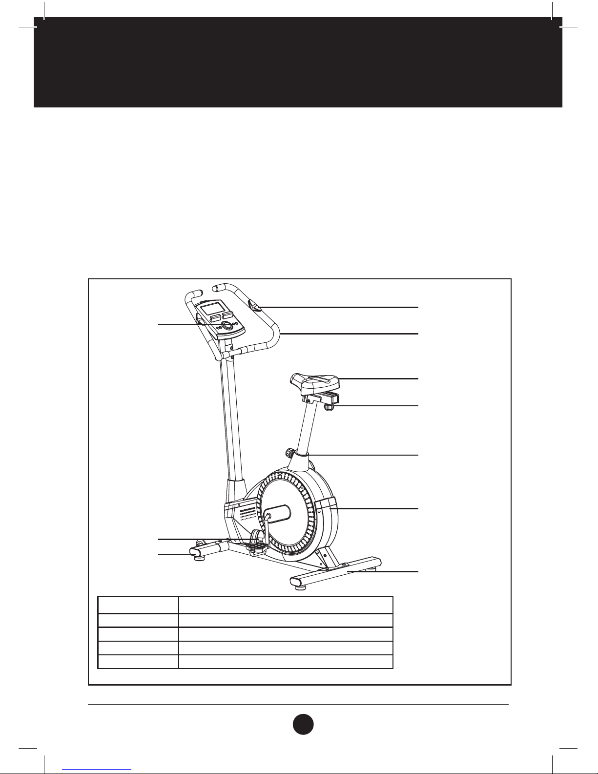
a healthier lifestyle. Before reading further, please review the drawing below and familiarise yourself with the
parts that are labelled.
Read this manual carefully before using the Trojan Power 500 Exercise Bike.
Functions Time / speed / distance / calories / hand pulse / RPM / watts
Tension Control Motorized
Saddle Vertical Adjustment
Set-up Size 1040 mm (l) x 590 mm (w) x 1370 mm (h)
User Weight 120 kg (maximum)
Front Stabiliser
Pedal
Hand Pulse
Handlebar
Adjustment Knob
Adjustment Knob
Seat
Main Cover
Rear Stabiliser
Computer
6
10390
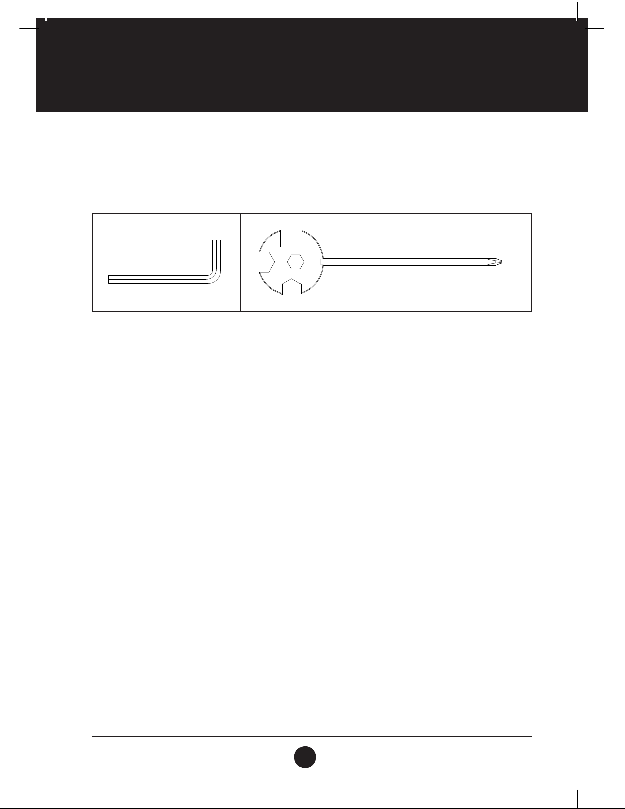
HARDWARE & TOOLS LIST
INSTRUCTIONS FOR ASSEMBLY
• Before you start to assemble, please check the hardware packaging to make sure all parts are included.
• Basic tools, such as spanners will be provided for assembly.
Allen Key S6
1 PC
Multi Hex Tool and
Phillips Screwdriver
S10, S13, S14, S15
1 PC

7
10390
PARTS LIST
No. Description Qty
1 Main Frame 1
2 Handlebar 1
3 Handlebar Post 1
4 Seat Post 1
5 Seat Sliding Tube 1
6 Front Stabiliser 1
7 Rear Stabiliser 1
8 Handlebar Foam Grip 2
9 Handlebar End Cap Ø25 x 1.5 2
10 Hand Pulse Sensor with Wire L = 850 mm 2
11 Screw ST4.2 x 20 2
12 Bolt M8 x 15-S6 10
13 Curve Washer Ø16 x Ø8 x 1.5 4
14 Computer 1
15 Extension Sensor Wire I L = 1000 mm 1
16 Screw M5 x 10 4
17 Handlebar Post Cover 1
18 Extension Sensor Wire II (L = 500 mm) 1
19 Left pedal 1
20 Right pedal 1
21 Washer I Ø20 x Ø8 x 2 6
22 Locking Knob M161.5 1
23 Bolt M8 x 35 2
No. Description Qty
24 Transportation wheel 2
25 Nut M8 5
26 Stabiliser end cap 4
27 Nut M10 4
28 Foot pad 4
29 Power Supply Wire L = 750 mm 1
30 Seat post cover 1
31
Pan Head Phillips Self Drilling Screw ST4.2
x 20
9
32 Adjustment Knob M10 1
33 Washer Ø20 x Ø10 x 2.0 1
34 Seat Sliding Tube cover 1
35 Seat Sliding Tube End Cap 2
36 Limit seat assembly 1
37 Washer Ø16 x Ø8 x 1.5 3
38 Seat Cushion 1
39 AC Adapter L = 2000 mm 1
40 Sensor with Wire L =3 00 mm 1
41 Motor 1
42 Seat Post Bushing 1
43 Screw ST2.9 x 12 2
44 Hexagon Nut 7/8” 2
45 Washer Ø23 x 34.5 x 2.5 1
46 Bearing Nut I 7/8” 1

8
10390
No. Description Qty
47 Bearing 2
48 Bearing Cup 2
49 Bearing Nut I 15/16” 1
50 Washer I Ø24 x 40 x 3.0 1
51 Belt 1
52 Belt Pulley with Crank 1
53 Flywheel 1
54 Nut M10 x 1.0 x 6 2
55 Eyebolt M6 x 36 2
56 U Bracket 2
57 Spring Washer Ø6 2
58 Nut M6 S10 2
59 Idle Wheel Bracket 1
No. Description Qty
60 Eyebolt M8 x 75 1
61 Bolt M8 x 20 1
62 Press Wheel 1
63 Washer Ø12 x Ø6 x 1.5 1
64 Screw M6 x 10 1
65 Left Chain Cover 1
66 Right Chain Cover 1
67 Left Crank Cover 1
68 Right Crank Cover 1
69 Plastic Bolt Ø8 x 32 3
70 Screw ST4.2 x 25 7
71 Nut S15 1
72 Motor tension cable L = 500 mm 1
PARTS LIST
9
10390
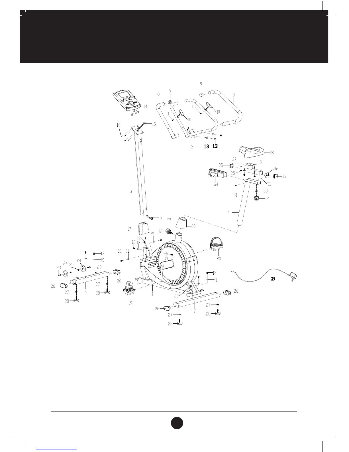
EXPLODED DRAWING
10
10390
ASSEMBLY STEPS
1. PREPARATION
• Before assembling make sure that you will have enough space around the item.
• Use the supplied parts and hardware for the assembly.
• Before assembling please check whether all the required parts have been supplied as per the exploded
drawing on the previous page.
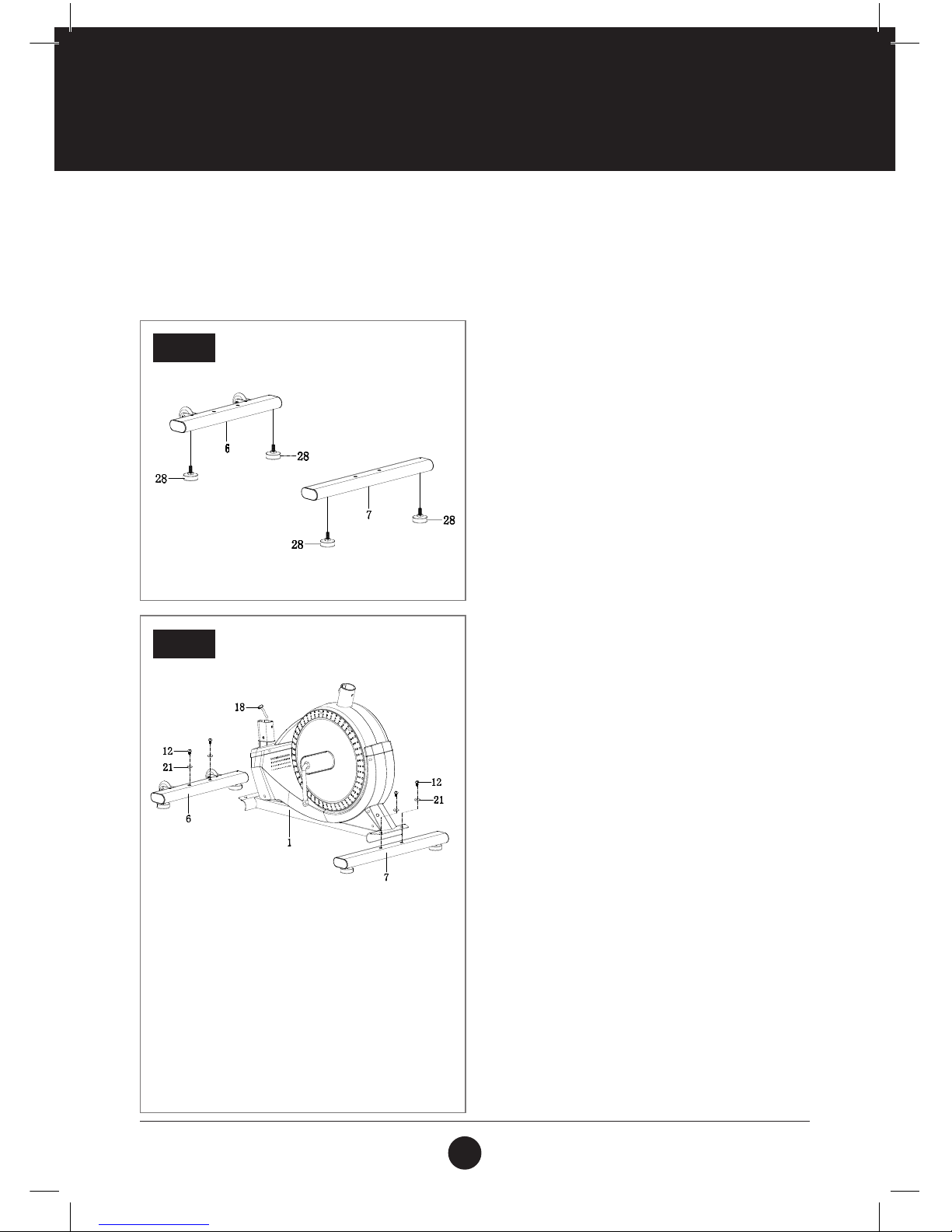
STEP 1
STEP 1: FOOT PAD INSTALLATION
Position 2 x Foot Pads (28) onto the
Front Stabiliser (6).
Position 2 x Foot Pads (28) onto the
Rear Stabiliser (7).
STEP 2: FRONT AND REAR STABILISERS
INSTALLATION
Remove 2 x M8 x 15 Bolts (12) and 2 x Ø8 x Ø20 Big
Flat Washers (21) from Front Stabiliser (6). Remove
2 x M8 x 15 Bolts (12) and 2 x Ø8 x Ø20 Big Flat
Washers (21) from Rear Stabiliser (7).
Position the Front Stabiliser (6) in front of the Main
Frame (1) and align bolt holes.
Attach the Front Stabiliser (6) onto the front curve
of the Main Frame (1) with the 2 x M8 x 15
Bolts (12) and 2 x Ø8 x Ø20 Big Flat Washers (21)
that were removed.
Position the Rear Stabiliser (7) behind the
Main Frame (1) and align bolt holes.
Attach the Rear Stabiliser (7) onto the rear curve of
the Main Frame (1) with 2 x M8 x 15 Bolts (12) and
2 x Ø8 x Ø20 Big Flat Washers (21) that
were removed.
STEP 2
 Loading...