

Trojan DUAL 500 Care Instructions And Assembly Manual
in your own space / in your own time
DUAL 500
ELLIPTICAL TRAINER
CARE INSTRUCTIONS AND ASSEMBLY MANUAL
CAUTION
READ ALL PRECAUTIONS AND
INSTRUCTIONS IN THIS MANUAL
BEFORE USING THIS EQUIPMENT
KEEP THIS MANUAL FOR
FUTURE REFERENCE
CALL
08-93015557
www.trojanfi tness.com.au

INDEX
SAFETY INSTRUCTION 3
BEFORE YOU BEGIN 4
HARDWARE LIST 5
ASSEMBLY STEP 6
COMPUTER FUNCTION 8
FITNESS TIPS AND TECHNIQUES 9
CONDITIONING GUIDELINES 10
WARM-UP AND COOL-DOWN 11
PART LIST 12
EXPLODED DRAWING 13
TROJAN 1 YEAR LIMITED WARRANTY 14
TROJAN REPAIRS PROCEDURE 15
PROOF OF PURCHASE 16

SAFETY INSTRUCTION
WARNING :
Safety instruction before using the TROJAN DUAL 500 ELLIPTICAL.
To reduce the risk of serious injury, read the following
1. Use the TROJAN DUAL 500 ELLIPTICAL only on a level surface.
2. Keep children and pets away from this equipment at all times.
3. The TROJAN DUAL 500 ELLIPTICAL should not be used by persons weighing more than 110kgs.
4. The TROJAN DUAL 500 ELLIPTICAL should be used by only one person at a time.
5. Be careful to maintain your balance while using, mounting, dismounting, folding, unfolding or assembling the TROJAN
DUAL 500 ELLIPTICAL, loss of balance may result in a fall and serious bodily injury.
6. Use the TROJAN DUAL 500 ELLIPTICAL only as described in the manual.
7. Before using this equipment to exercise, always do stretching exercises to properly warm up.
8. Always make sure all bolts and nuts are tightened prior to each use.
WARNING
Before starting any exercise or conditioning program you should consult with your personal physician to see if you
require a complete physical exam. This is especially important if you are over the age of 35, have never exercised before,
are pregnant, or suffer from any illness.
1571AU-4
BEFORE YOU BEGIN
Thank you for choosing the TROJAN DUAL 500 ELLIPTICAL. We take great pride in producing this quality product and
hope it will provide many hours of quality exercise to make you feel better, look better and enjoy life to its fullest.
Yes, it’s a proven fact that a regular exercise program can improve your physical and mental health. Too often, our busy
lifestyles limit our time and opportunity to exercise. TROJAN DUAL 500 ELLIPTICAL provides a convenient and simple
method to begin your assault on getting your body in shape and achieving a healthier lifestyle.
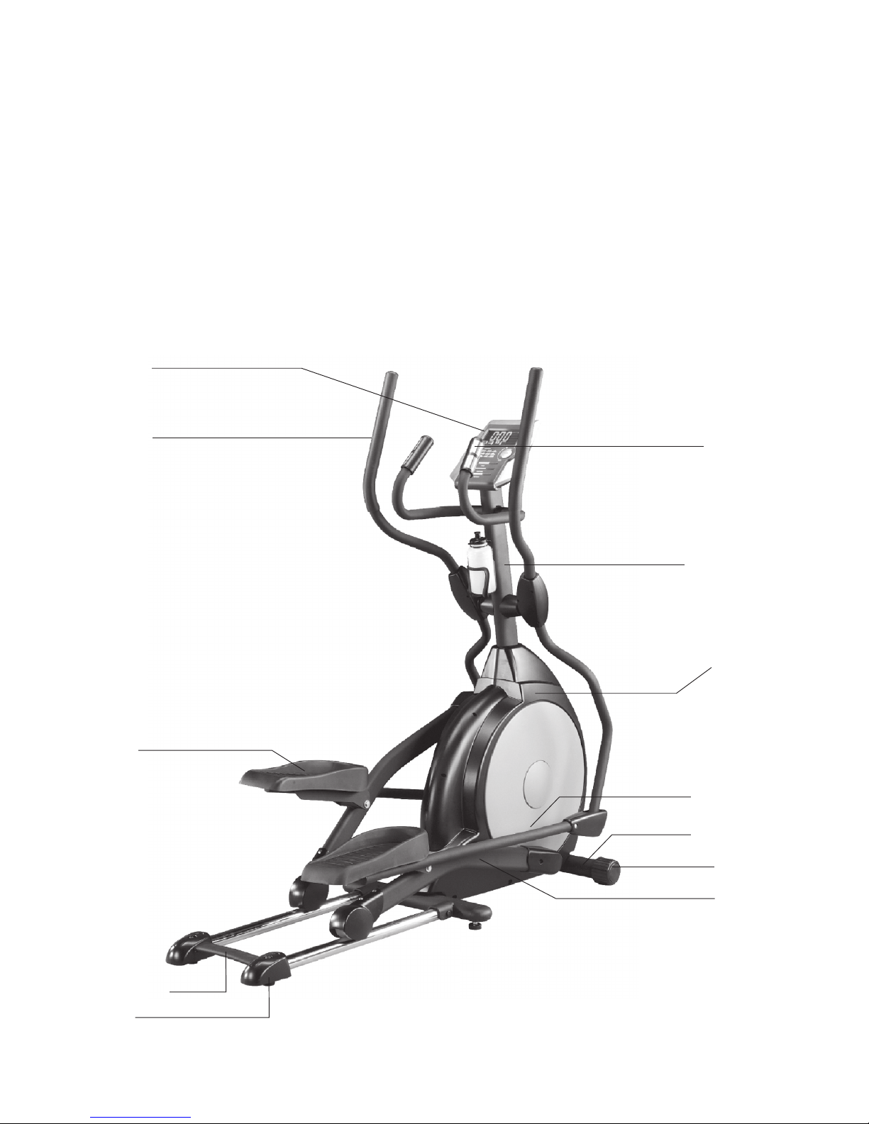
Before reading further, please review the drawing below and familiarize yourself with the par ts that are labeled.
• Read this manual carefully before using the TROJAN DUAL 500 ELLIPTICAL.
Handlebar
Computer Mast
Computer Mast Cover
Computer
Front Stabilizer
Pedal Arm
Pedal (L)
Transformer
Rear Stabilizer
Handlepulse
Connecting Arm
Cushion
1571AU-5
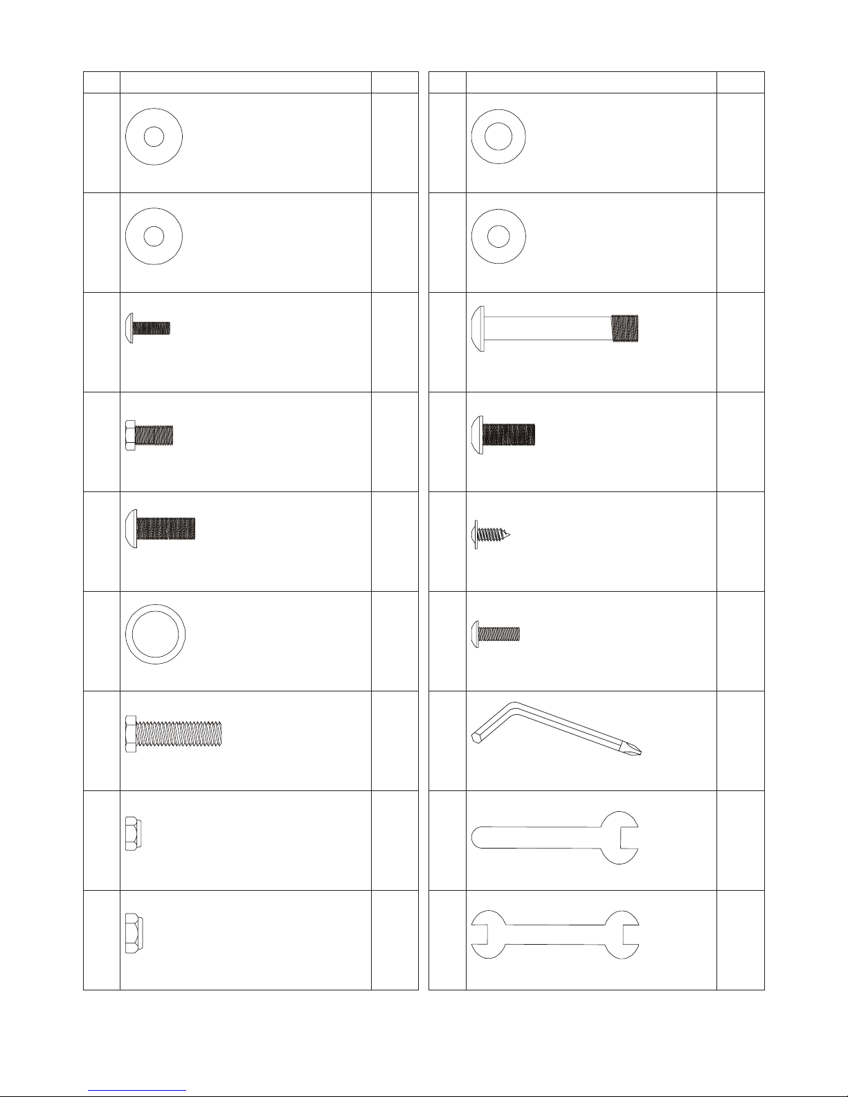
HARDWARE LIST
No. Description Q'ity
97
Flat Washer (5/16”x 23 x 1.5T)
4
102
Curved Washer (5/16”x 23 x 2T)
2
78
Phillips Head Screw (M5 x 10m/m)
* these four screws are attached in the back of the console.
4
70
Hex Head Screw (5/16” x 15m/m)
8
75
Button Head Socket Screw
(5/16” x 15m/m)
6
101
Wavy Washer (ø17 )
2
71
Hex Head Screw (5/16 x 32m/m)
2
105
Nylon Nut (5/16” x 7T)
2
89
Nylon Nut (3/8” x 7T)
2
NOTE :
The described parts are all you need to assemble this machine.
Before starting assembly, please check the hardware packing to make sure they are included.
No. Description Q'ity
94
Flat Washer (3/8” x 19 x 1.5T)
2
98
Flat Washer (5/16” x 20 x 1.5T)
4
77
Button Head Socket Screw (3/8 x 2-1/4”)
2
76
Button Head Socket Screw (5/16 x 3/4”)
2
84
Self Tapping Screw (ø3.5 x 12m/m)
8
79
Phillips Head Screw (M5 x 15m/m)
8
108
Combination M5 Allen Wrench & Phillips
Head Screw Driver
1
110
Wrench (12m/m )
1
111
Wrench (13/14m/m)
2
1571AU-6
ASSEMBLY STEP
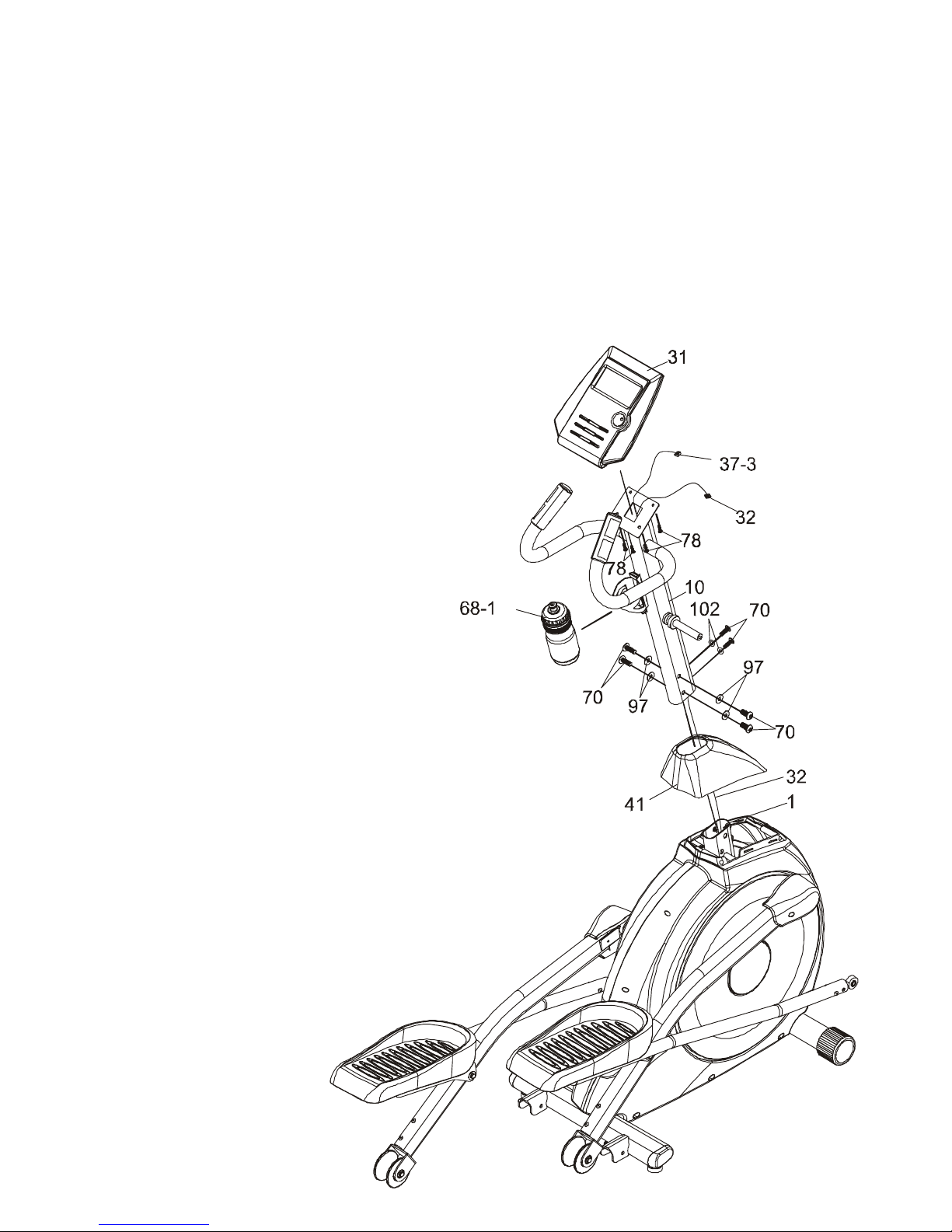
STEP 1 CONSOL MAST ASSEMBLY
• Locate the Consol Mast (10) and Consol Mast Cover (41) and slide the Cover onto the Mast as far as it will go.
• Make sure the Consol Mast Cover (41) is facing the correct way.
• At the top opening of the Main Frame (1) of the elliptical is a Computer Cable (32).
• Unravel and straighten out the Computer Cable (32) and feed it into the bottom of the console Mast Tube (10) and
out of the top opening.
• Install the Consol Mast (10) into the receiving bracket in the top of the Main Frame (1).
• Attach the 5/16” x 23 x 1.5T Flat Washers (97) onto the 5/16” x 15m/m Hex Head Screws (70) and the 5/16” x 23 x
2T Curved Washers (102) onto the 5/16” x 15m/m Hex Head Screws (70).
• Tighten using the 12m/m Wrench (110).
CAUTION:
Ensure that cables are not damaged during assembly
or when tightening screws.
• There are three electrical wire connectors at the
top opening of the Consol Mast (10), two 2 pin
Hand pulse Cables (37-3), one Computer Cable
(32). Connect these to the mating connectors on
the back of the Consol (31).
• The connectors are keyed so you cannot plug them
in the wrong way so do not force them.
• Placing the excess wire back into the Consol Mast
(10), carefully install the Consol (31) onto the
mounting plate of Consol Mast (10) and secure us-
ing the 4 pcs of M5 x 10m/m Phillips Head Screws
(78) and tighten with Phillips Head Screwdriver
(108)
1571AU-7
ASSEMBLY STEP
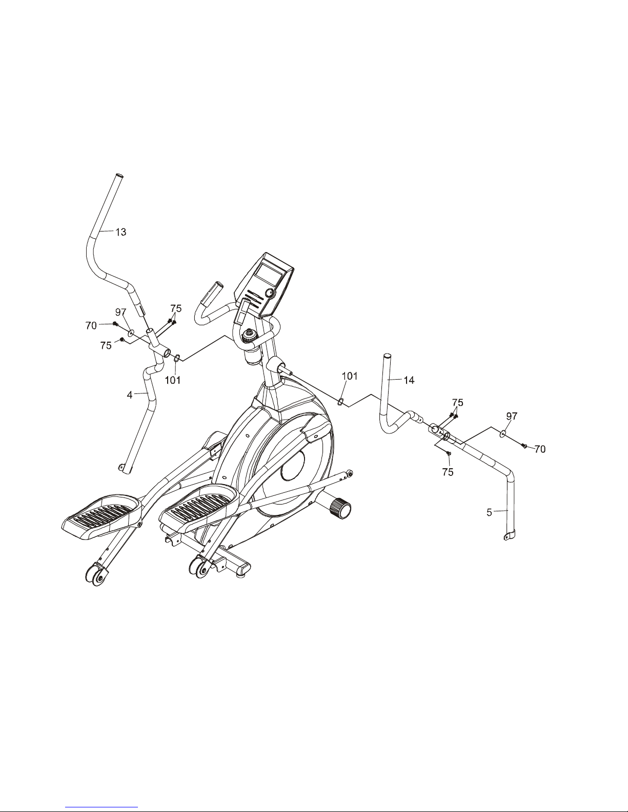
STEP 2 HANDLE BAR ASSEMBLY
• Install the 2 ø17 Wave Washers (101) onto the Left and Right side of the Handle Bar axle.
• Slide the Lower Left and Right Handle Bars (4&5) onto the appropriate side of the axle.
• Put the 2 5/16” x 23 x 1.5T Flat Washers (97) onto the 2 5/16” x 15m/m Hex Head Screws (70) and tighten, into the
threaded holes in the ends of the axle.
• Install the Left and Right Handle Bars (13&14) into the Lower Left and Right Handle Bars (4&5) with 5/16 x15m/m
Button Head Socket Screws (75), using the Combination M5 Allen Wrench & Phillips Head Screw Driver (108).
1571AU-8
ASSEMBLY STEP
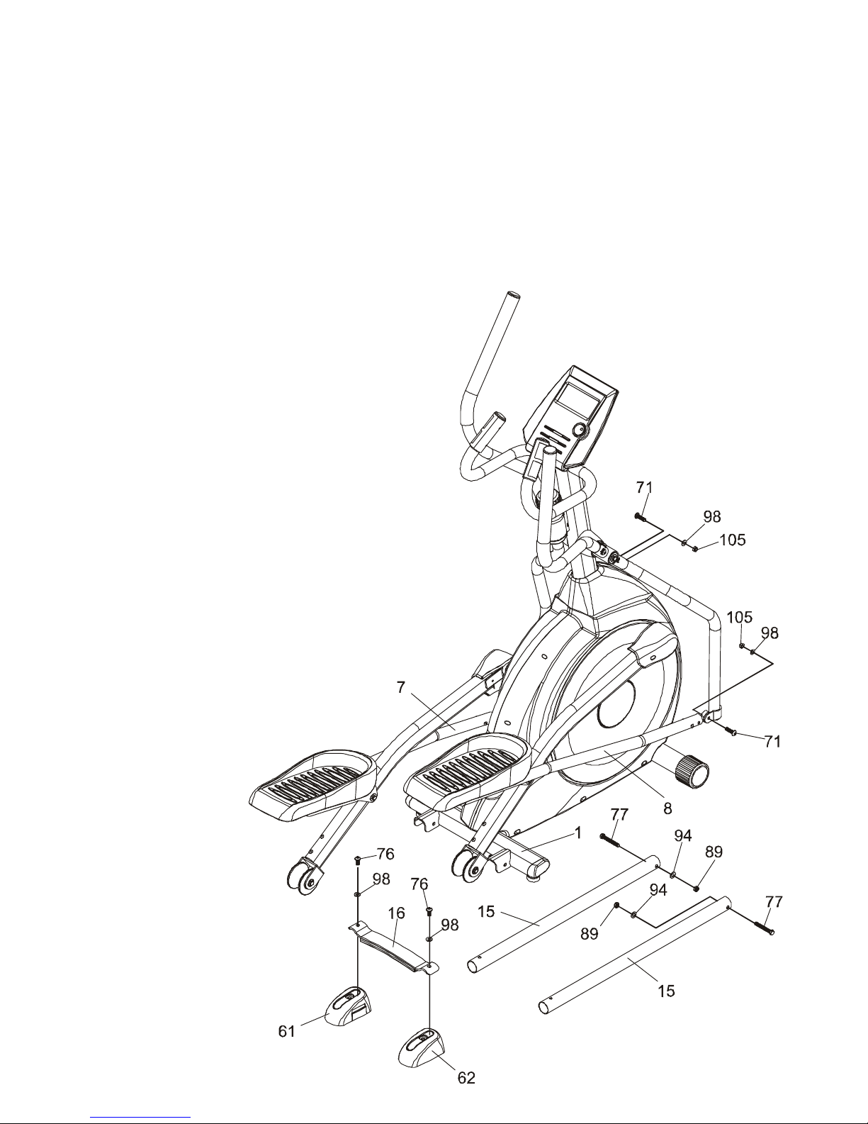
STEP 3 CONNECTING ARM ASSEMBLY
• Align the hole in the end of the Connecting Arms (L&R)(7&8)(pivoting rod end) with the hole in the bracket of the
Lower Handle Bars (L&R)(3&4).
• The rod end should be on the inside of the Lower Handle Bars (L&R)(3&4) bracket. Take 2 5/16” x 1-1/4” Hex Head
Screws (71) and place them through the Lower Handle Bars (L&R)(3&4) bracket and the rod end.
• Attach the 2 5/16” x 20 x 1.5T Flat Washers (98), 2 5/16” x 7T Nylon Nuts(105) and tighten firmly using the 12m/m
Wrench (111) on the 5/16” x 7T Nylon Nut (105) and on the 5/16” x 1-1/4” Hex Head Screw(71).
• Attach the 2 Rails (15) onto the receiving bracket in the end of Main Frame(1) with 2 3/8” x 2-1/4” Button Head
Socket Screws(77), 2 3/8” x 19 x 1.5T Flat Washers(94) and 2 3/8” x 7T Nylon Nut (89) by using the 13/14m/m
Wrench (111).
• Put the Lug Cover (L) (61) and Lug Cover (R)(62) onto
the Iron Plate (16).
• Attach the Rails (15) with 2 5/16” x 3/4” Button Head
Socket Screws (76) and 2 5/16” x 20 x 1.5T Flat Washers
(98) by using Combination M5 Allen Wrench & Phillips
Head Screw Driver (108).
 Loading...