

Page 1

Lüftungsgeräte
Air Handling Units
Montage-, Betriebs- und
Wartungsanleitung
Assembly, Operation and
Maintenance Instructions
Technische Änderungen vorbehalten! Version: 09/2015
Page 2

T R O G E S AIRSET – Montage-, Betriebs- und Wartungsanleitung
AIRSET – Assembly, Operation and Maintenance Instructions
Inhaltsverzeichnis Table of contents
Allgemeines General .......................................................................................... - 3 -
Hinweiszeichen Instruction Signs ....................................................................... - 3 -
Sicherheitshinweise Safety Instructions ............................................................ - 4 -
Anlieferung Delivery ............................................................................................ - 5 -
Transport Transport ............................................................................................. - 6 -
Lagerung Storage ................................................................................................ - 7 -
Aufstellung Installation ....................................................................................... - 8 -
Montage Assembling ........................................................................................... - 9 -
Inbetriebnahme und Wartung Start-up and Maintenance ............................ - 12 -
Ventilatorteil Fan section ................................................................................. - 13 -
Luftfilter Air Filter ............................................................................................... - 15 -
Erhitzerteil Heater ............................................................................................ - 16 -
Elektroerhitzer Electric Heater ........................................................................ - 18 -
Kühlerteil Cooler .............................................................................................. - 18 -
Direktverdampfer / Kondensator Evaporator / Condenser ............................ - 20 -
Plattenwärmetauscher Plate Heat Exchanger ............................................... - 21 -
Rotationswärmetauscher Rotary Heat Exchanger ......................................... - 21 -
Jalousieklappen Damper ................................................................................. - 22 -
Schalldämpfer Silencer .................................................................................... - 23 -
Düsenbefeuchter Air Washer ........................................................................... - 23 -
Verdunstungsbefeuchter Honey Comb .......................................................... - 26 -
Dampfbefeuchter Steam Humidifier ................................................................ - 26 -
Demontage Disassembling ............................................................................... - 27 -
Entsorgung Disposal ......................................................................................... - 28 -
Störungsbehebung Trouble Shooting .............................................................. - 28 -
Inbetriebnahmeprotokoll Start-up journal ....................................................... - 29 -
Leistungsumfang und Intervalle für die Wartung Scope of Services ........... - 30 -
Anschlussbilder Connection Diagrams .......................................................... - 40 -
Hygiene Checkliste
Hygienic Checklist………………………………………….. -43-
Konformitätserklärung Declaration of Conformity......................................... - 42 -
- 2 -
Page 3
T R O G E S AIRSET – Montage-, Betriebs- und Wartungsanleitung
AIRSET – Assembly, Operation and Maintenance Instructions
Allgemeines
Diese Montage-, Betriebs- und Wartungsanleitung gilt ausschließlich für TROGES
Lüftungsgeräte der Typen AIRSET und
AIRSET X-Large.
Die Montage-, Betriebs- und
Wartungsanleitung ist vor Beginn der Montage,
Inbetriebnahme oder Wartung vom jeweils
beauftragten Personal zu lesen. Die Vorgaben
in dieser Anleitung müssen eingehalten
werden.
Bei Nichteinhaltung der Montage-, Betriebsund Wartungsanleitung erlischt der
Gewährleistungsanspruch gegenüber der Fa.
TROGES Ges.m.b.H.
Die Montage-, Betriebs- und Wartungsanleitung muss ständig am Aufstellungsort des
Lüftungsgerätes verfügbar sein.
Die Montage-, Betriebs- und Wartungsanleitung befindet sich zum Zeitpunkt der
Auslieferung immer auf der Innenseite der
Ventilatortüre um muss vor Inbetriebsetzung
des Lüftungsgerätes entfernt werden.
Hinweiszeichen
Bei Nichtbeachten der hiermit
gekennzeichneten Hinweise kann es zu
einer Gefährdung von Personen
kommen.
Bei Nichtbeachten der hiermit
gekennzeichneten Hinweise kann es zu
einer Beschädigung des Lüftungsgerätes
kommen.
Bei Nichtbeachten der hiermit
gekennzeichneten Hinweise besteht
Gefahr durch elektrische Spannung an
elektrischen Bauteilen. Es besteht die
Gefahr eines Stromschlages mit
Gesundheitsgefährdung bzw.
Todesfolge.
Zusätzlich zu den Hinweisen in der Montage-,
Betriebs- und Wartungsanleitung, sind noch
Hinweise in Form von Aufklebern am
Lüftungsgerät angebracht. Diese sind in
gleicher Weise einzuhalten.
Attention
General
These Assembly, Operation and
Maintenance Instructions apply exclusively
to TROGES air handling units of types
AIRSET standard and AIRSET X-large.
The Assembly, Operation and
Maintenance Instructions must be read by
the personnel before starting assembly,
start up or maintenance. The instructions
must be adhered to.
Failure to adhere to the Assembly,
Operation and Maintenance Instructions
will render warranty claims directed to
TROGES invalid.
The Assembly, Operation and
Maintenance Instructions have to be
always available at installation location of
the air handling unit.
At delivery of the AHU the Assembly,
Operation and Maintenance Instructions is
placed inside the door of the fan unit and
have to be replaced before beginning
start up.
Instruction signs
Failure to observe the instructions
marked thus may endanger persons.
Failure to observe the instructions
marked thus may damage the air
handling unit.
Failure to observe the instructions
marked thus the danger of electrical
hazard exists, with health risk
respectively with fatal consequences.
In addition to the Assembly, Operation
and Maintenance Instructions all
instruction signs and labels have to be
adhered similarly.
- 3 -
Page 4

T R O G E S AIRSET – Montage-, Betriebs- und Wartungsanleitung
AIRSET – Assembly, Operation and Maintenance Instructions
Sicherheitshinweise
Für die Montage, Inbetriebnahme und
Wartung des Lüftungsgerätes darf nur
ausreichend qualifiziertes Personal
eingesetzt werden, welches die Arbeiten
beurteilen, Gefahren erkennen und
vermeiden können.
Den elektrischen Anschluss des
Lüftungsgerätes darf nur eine Elektrofachkraft vornehmen.
Für den Elektrischen Anschluss gelten die
ÖVE bzw. die jeweiligen nationalen und
internationalen Vorschriften und Normen, die
EN60204 und die Bestimmungen des örtlichen
Elektroversorgungsunternehmens (EVU).
Sicherheits- und Überwachungseinrichtungen
dürfen nicht entfernt oder außer Funktion
gesetzt werden.
Das Lüftungsgerät darf nur in technisch
einwandfreiem Zustand betrieben werden.
Störungen und Schäden, die zu
Beeinträchtigungen des Betriebes führen
könnten, müssen umgehen und fachmännisch
behoben werden.
Für den Austausch von defekten Gerätekomponenten dürfen ausschließlich original
TROGES- Ersatzteile eingesetzt werden.
Das Lüftungsgerät darf nur innerhalb des am
Datenblatt vorgegebenen Leistungsbereichs
betrieben werden.
Das Lüftungsgerät dient ausschließlich der
Förderung und Aufbereitung von Luft im
Bereich von –25°C bis +40°C, ohne
gesundheitsgefährdende, brennbare, explosive
und aggressive Beimengungen.
Es dürfen keine Beimengungen in der Luft
enthalten sein, die in Verbindung mit Wasser
(z.B.: Kondensat) zu aggressiven Stoffen
werden, und die verwendeten Materialien
angreifen.
Besonders bei Abluftanlagen ist darauf zu
achten, dass die Luft nicht belastet ist mit zum
Beispiel Fetten oder sonstigen Partikeln, die
die Leistungsfähigkeit der Lüftungsanlage oder
einzelner Komponenten beeinträchtigen
könnten. Auch darf die Ozonkonzentration in
der Luft nicht über den natürlichen
Konzentrationen liegen.
Safety instructions
Only adequately qualified personnel
may be employed for the assembly,
start-up and maintenance of the air
handling unit.
Only qualified electricians may connect
the air handling unit.
The ÖVE or applicable national and
international regulations, EN60204 and the
regulations of the local power supply
company (EPSC) apply to the electrical
connection.
Safety and monitoring installations may not
be removed or disabled.
The air handling unit may only be
operated in technically perfect condition.
Faults and damages impairing the
operation must be avoided and expertly
repaired.
Use only original TROGES spare parts for
the exchange of defective unit
components.
The air handling unit may only be
operated within the power range specified
in the data sheet.
The air handling unit serves only for the
supply and conditioning of air in the range
from –25°C to +40°C, without combustible,
explosive and aggressive admixtures
harmful to health.
The air shall not contain substances, which
in combination with water (condensate)
may generate aggressive substances,
which damage the used materials of the
AHU.
Grease or other substances in the air which
might reduce the performance of the AHU
or components of it must be avoided. In
addition, high concentrations of ozon must
be avoided.
- 4 -
Page 5

T R O G E S AIRSET – Montage-, Betriebs- und Wartungsanleitung
AIRSET – Assembly, Operation and Maintenance Instructions
Beachten sie unbedingt die
Kondensationsgrenzen. Tabelle 1 zeigt den
Zusammenhang zwischen Temperaturdifferenz
Außen und Innen und der relativen
Luftfeuchtigkeit. Die Werte aus der Tabelle
dienen als Anhaltswerte, sind aber keine
Garantie zur Vermeidung von Kondensation.
Je nach Gehäusekomponenten kann es zu
Abweichungen kommen.
Tabelle 1 / table 1
Temperaturdifferenz zwischen
Geräteinnen- und außenseite
Temperature difference between
unit inside and outside
[K] AIRSET AIRSET X-Large
30 48 53
25 55 58
20 60 65
15 70 72
10 77 80
max. zulässige relative Luftfeuchtigkeit in [%]
Anlieferung
AIRSET Lüftungsgeräte werden hauptsächlich
in mehreren Liefereinheiten geliefert, deren
Größen entsprechend den Kundenwünschen
und den Transportmöglichkeiten angepasst
sind.
Geräteteile, deren Abmessungen die
maximalen Maße von Standardtransporten
überschreiten, werden komplett- oder
teilzerlegt angeliefert und müssen dann vor Ort
zusammengebaut werden.
Bei Übernahme sind die einzelnen
Liefereinheiten auf Richtigkeit und
Vollständigkeit zu überprüfen.
Bei offensichtlichen Transportschäden sind
diese auf den Lieferpapieren des
Transporteurs zu vermerken.
Bei Transportschäden die erst nach entfernen
der Verpackung augenscheinlich werden, sind
diese zu fotografisch zu dokumentieren und
schriftlich an die TROGES Ges.m.b.H. zu
melden.
Ohne diese schriftliche Meldung kann eine
Schadensbearbeitung nicht durchgeführt
werden.
Note the condensation limits of casing.
Table 1 shows the coherence between
temperature difference outside and inside
of the casing and the relative humidity. All
Values in table 1 are only reference values
and do not guaranty that any condensate
may. Depending on the unit design are
variations possible.
max. allowed relative humidity in [%]
Delivery
AIRSET air handling units are mainly
delivered in several components the sizes
of which are adjusted to suit the wishes of
the customers and the transport
possibilities.
Delivery sections which are too large for a
standard transport may be delivered in
completely knocked down version (CKD)
or in semi knocked down version (SKD).
On acceptance the individual delivery
units have to be verified and checked the
completeness.
Obvious damages have to be reported
immediately and noted on the shipping
documents of the carrier.
Damages which are visible only after
removing the packaging, have to be
reported immediately and some picture
have to be sent together with a short
description to TROGES Ges.m.b.H.
Without the written notification we can not
handle the claim.
- 5 -
Page 6

T R O G E S AIRSET – Montage-, Betriebs- und Wartungsanleitung
AIRSET – Assembly, Operation and Maintenance Instructions
In beiden Fällen muss jedoch vor dem Einbau
der Lüftungsanlagen mit der Troges
Ges.m.b.H. Kontakt aufgenommen werden.
Transport
Die Geräte dürfen nur in Einbaulage
transportiert werden.
Um beim Transport mit Gabelstapler oder
anderen Transporthilfen eine
Beschädigung der Bodenpaneele zu
vermeiden, muss darauf geachtet werden,
dass Tragarme unter den Geräterahmen
bzw. unter den Transportpaletten liegen.
Beim Transport mit einem LKW sind die
Lüftungsgeräte vor Witterungseinflüssen zu
schützen.
Die Lüftungsgeräte müssen beim Transport mit
einem LKW gegen verrutschen gesichert
werden. Grundrahmenfüße müssen
entsprechend verzurrt werden, weil diese
ausschließlich für statische Belastungen
ausgelegt sind.
Beim Verhub von Geräten muss auf folgendes
geachtet werden:
Treten sie niemals unter schwebende
Lasten. Es besteht die Gefahr, dass es bei
schadhaften Hebezeugen, Transportmittel
oder Geräteteilen zu Unfällen kommt.
Schwere Verletzungen oder der Tod könne
die Folge daraus sein.
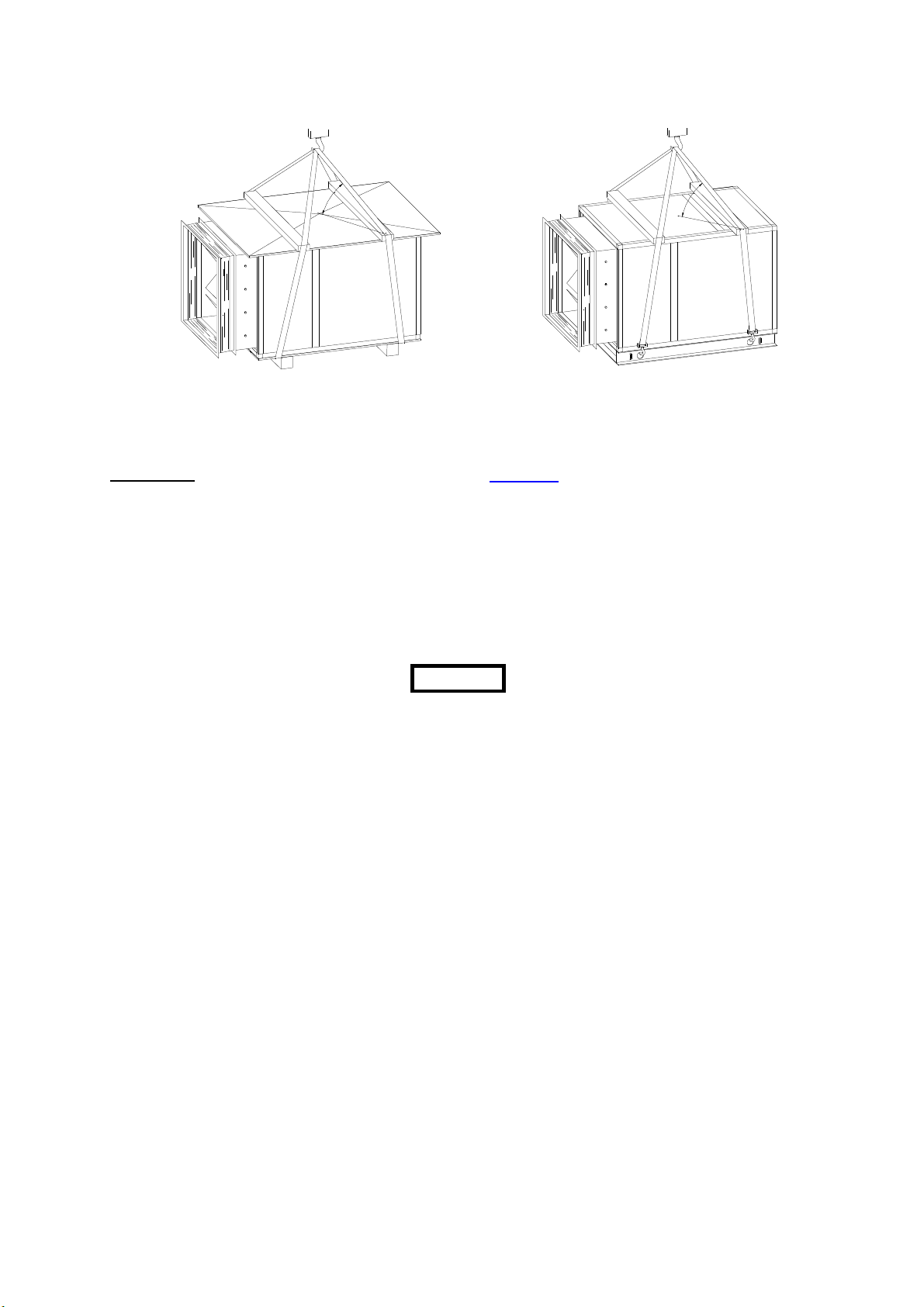
Geräte ohne Grundrahmen werden auf
Einwegholzpaletten angeliefert. Sie können mit
geeigneten Transportgurten hochgehoben
werden. Die Gurte müssen entsprechend der
Gerätebreite bzw. bei wetterfesten Geräten
entsprechend dem Dachüberstand
ausgespreizt werden (siehe Bild 1a).
Bei Geräten mit Grundrahmen können Haken
an den Transportgurten in die Ausnehmungen
am Grundrahmen eingehängt werden. Für die
Ausspreizung der Gurte gilt das gleiche wie bei
Geräten ohne Grundrahmen (siehe Bild 1b)
Attention
In both cases get into contact with
TROGES Ges.m.b.H, before the AHU is
installed.
Transport
The units may only be transported in
installation position.
In order to avoid damaging the ground
panels when transporting the unit with a
forklift or other transport equipment it
must be ensured that support arms are
positioned under the unit frame or
under the transport pallets.
Protect the air handling units from the
effects of the weather while being
transported in trucks.
The air handling units must be secured to
avoid skidding during truck transport. Lash
down base frame legs since these are
exclusively designed for static loads.
Take care of the following when you lift the
AHUs.
Never stand under floating loads. When
lifting tools, means of transportations or
parts of the AHU are damaged the risk
of accidents exists. Severe or fatal
injuries can be the effect.
Units without base frame are delivered on
one-way wooden pallets. They can be
lifted with suitable transport belts. The belts
must be spread out in accordance with
the unit width or in accordance with the
roof overhang in the case of weatherproof
units (see figure 1a).
On units with base frame the hooks in the
transport belts can be engaged in the
recesses on the basic frame. With regard
to the spreading out of the belts the same
applies as for units without base frame (see
figure 1b)
- 6 -
Page 7
T R O G E S AIRSET – Montage-, Betriebs- und Wartungsanleitung
AIRSET – Assembly, Operation and Maintenance Instructions
°
0
6
.
n
i
m
Bild 1a Bild 1b
figure 1a figure 1b
Lagerung
Storage
Bei längerer Zwischenlagerung sind die
Lüftungsgeräte in geschlossenen, sauberen,
trockenen, gut durchlüfteten und temperaturkonstanten Räumen zu lagern. Die zulässige
Lagertemperatur für nicht installierte Geräte
beträgt von -10°C bis 50°C.
On prolonged intermediate storage the air
handling units must be kept in closed,
clean, dry, well-ventilated rooms with
constant temperatures. The allowed
storage temperatures for not installed units
are from -10°C to 50°C.
Die Lüftungsgeräte sind nach der
Anlieferung aus der Kunststofffolie
auszupacken. Es besteht die Gefahr von
Weißrostbildung.
Bei Geräte für Außenaufstellung (wetterfest)
ist nach der Montagefertigstellung eine
Durchlüftung der Geräte (auch hinter der
Folie) zu gewährleisten wobei der Eintrag von
Regen und Schnee zu verhindern ist.
Attention
The air handling units must be
unpacked from the plastic foil
after delivery. Risk of white rust
formation.
After the assembly of weather proof
units the units need to be well aired to
avoid condensation- also behind the
transparent sheet.
Nach der Einlagerung der Geräte sind die
Oberseiten mit Karton oder Papier gegen
Staub zu schützen.
Following storage of the units, protect the
upper sides with cardboard or paper
against dust.
Bei der Ventilator-/Motoreinheit müssen die
Keilriemen abgenommen werden. Bei längerer
Zwischenlagerung müssen die Ventilator- und
Motorlager alle 3 Monate mindestens 2
Undrehungen gedreht werden. Bereits kleinste
Korrosionsschäden vermindern die
Lagerlebensdauer erheblich. Bei extremen
Temperaturschwankungen kann es zu
Kondensatbildung in den Lagern kommen
(Neufettung).
On the fan/motor unit the V-belts must be
removed. Following extended
intermediate storage the fan and motor
shafts must be moved manually each 3
month with minimum 2 rotations. Already
small corrosion damage will considerably
reduce the bearing life. In case of extreme
temperature differences, condensate will
be built up in the bearings. (new
lubrication of bearing)
Beigepacktes Material wie z.B.:
Montagematerialien oder lose Anlagenteile
müssen gegen Diebstahl gesichert werden.
Protect enclosed material and loose
components need to be protected
against theft.
°
0
6
.
n
i
m
- 7 -
Page 8
T R O G E S AIRSET – Montage-, Betriebs- und Wartungsanleitung
AIRSET – Assembly, Operation and Maintenance Instructions
Aufstellung
Für die Aufstellung der Geräte ist ein ebener,
waagrechter, stabiler, trockener und
besenreiner Boden erforderlich, auf dem das
Gerät vollflächig aufliegen muss. Nur so kann
ein sachgemäßer Zusammenbau gewährleistet
werden.
Bei der Aufstellung der Lüftungsgeräte auf
Streifenfundamenten ist unbedingt ein
Grundrahmen vorzusehen.
Zur Vermeidung von Körperschallübertragungen ist es notwendig, zwischen
Geräteboden und Fundament schwingungsdämmende Unterlagen vorzusehen.
Bei Verwendung von Mafundunterlagen zur
Schwingungsdämpfung sollte unbedingt ein
Grundrahmen vorgesehen werden.
Installation
A level, horizontal, dry and clean floor is
required for the installation of the units,
while the entire area of the unit must be in
contact with the floor. Proper assembly
can only be ensured in this way.
When installing the air handling units on
rigid foundations, the provision of a base
frame is indispensable.
In order to avoid solid-borne vibration
transmission it is necessary to provide
vibration dampers between unit floor and
foundation. If Mafund vibration isolation is
used a base frame is mandatory.
Auf den Bedienungs- und Anschlussseiten ist
zu Service- und Wartungszwecken die
Zugängigkeit aller Gerätekomponenten und
lufttechnischer Bauteile zu gewährleisten (min.
Gerätebreite).
Bei Geräteaufstellung an der Wand ist ein
Abstand von 300 mm einzuhalten.
Bei Geräten mit Kondensatanschlüssen, muss
darauf geachtet werden, dass die Höhe der
Unterkonstruktion mindestens der
erforderlichen Sifonhöhe entspricht.
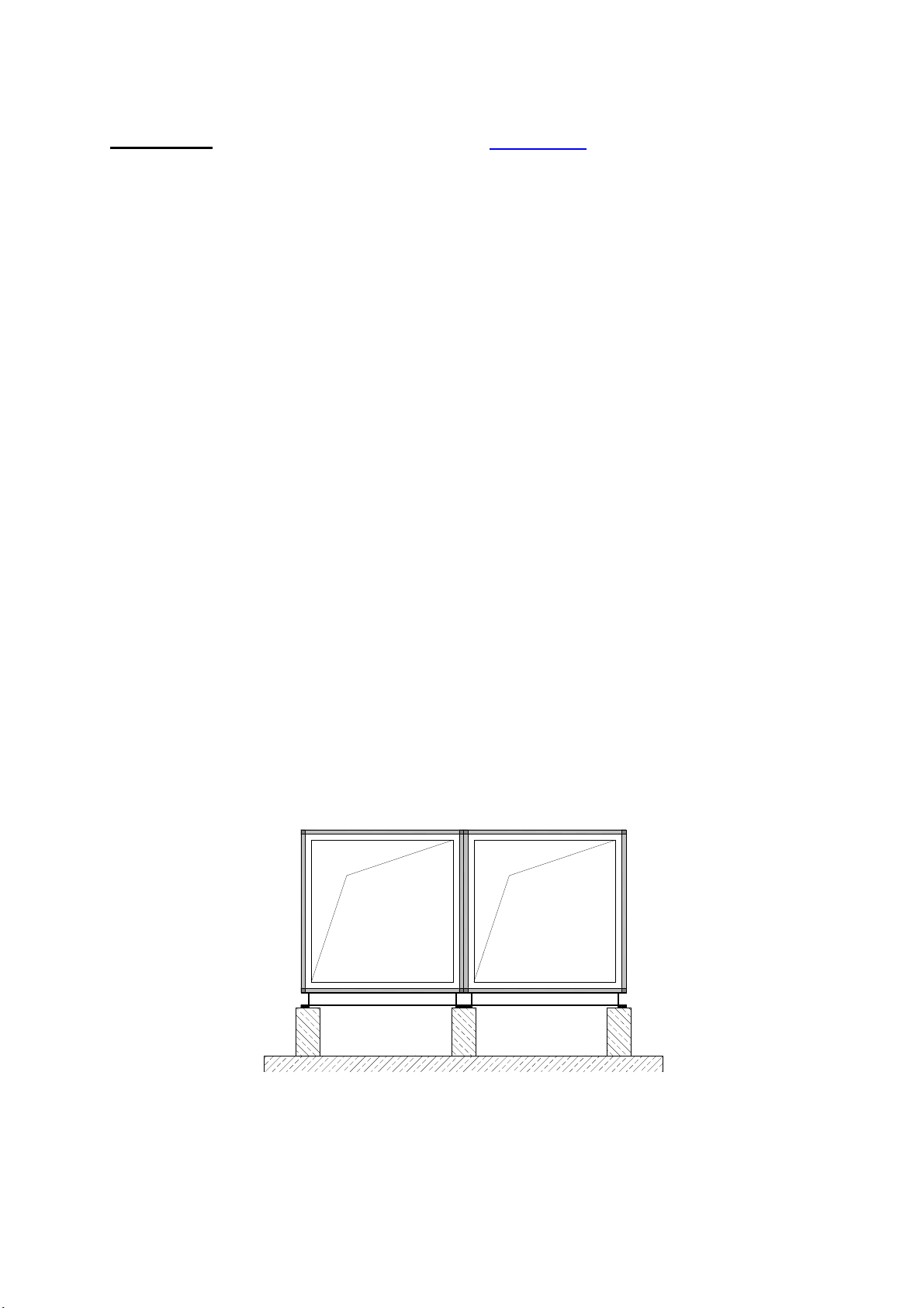
Die Auflagepunkte der Unterkonstruktion
müssen bei jeder Geräteteilung situiert sein,
jedoch darf der Abstand zwischen den
Auflagepunkten 1500mm nicht überschreiten.
Bei Geräten die
nebeneinander
angeordnet sind, müssen
diese unbedingt mittig
unterstützt werden (siehe
Bild 2).
Bild 2
figure 2
For service and maintenance on all
components sufficient space is required
(min. unit width).
If the units are positioned close to a wall a
minimum distance of 300 mm shall be
observed.
When water drain connections exists, take
care that the height of the substructure is
according to the necessary siphon height.
Under each unit split are supporting points
needed, but the maximum distance
between the supporting point shall be not
more than 1500mm.
A middle substructure
is needed for unit
combinations side by
side (figure 2).
- 8 -
Page 9

T R O G E S AIRSET – Montage-, Betriebs- und Wartungsanleitung
AIRSET – Assembly, Operation and Maintenance Instructions
Geräte die im Freien aufgestellt werden,
müssen durch bauseitige Maßnahmen,
entsprechend der zu erwartenden Windlast,
gegen Winddruck gesichert werden. Bei
Montageunterbrechungen und bei Montagen,
die durch die Troges Ges.m.b.H. durchgeführt
werden, müssen die Sicherungsmaßnahmen
ebenfalls bauseitig durchgeführt werden.
Die Höhe der Unterkonstruktion muss
entsprechend der örtlichen Schneelage
gewählt werden.
Bei Geräte die im Freien aufgestellt werden,
muss gem. EN13779 die Fortluft vertikal nach
oben ausgeblasen werden. Die
Außenluftansaugung hat mindestens 3m über
Bodenniveau zu erfolgen.
Montage
Die einzelnen Geräteteile sind durch Aufkleber
gekennzeichnet, an welcher Position innerhalb
der Anlage, die jeweiligen Geräteteile situiert
werden müssen.
Das erforderliche Verbindungsmaterial ist in
einem Geräteteil mit Revisionstüre (meistens
der Ventilatorteil) beigepackt. Der Kasten ist
mit der Liste des beigepackten Materials
gekennzeichnet.
Zwischen den einzelnen Geräteteilen muss vor
der Montage das beiliegende Dichtungsband
umlaufend auf die Geräterahmen geklebt
werden.
Die einzelnen Geräteteile müssen so eng wie
möglich aneinandergestellt werden bevor sie
mit den außenliegenden Verbindungswinkeln
bzw. den innenliegenden Verbindungsklammern verbunden werden.
Abhängig vom Geräterahmentyp und der
Gehäusewandstärke, ob wetterfeste oder
Hygieneausführung kommen entweder
außenliegende Verbindungswinkel, oder
innenliegende Verbindungsklammern zur
Anwendung.
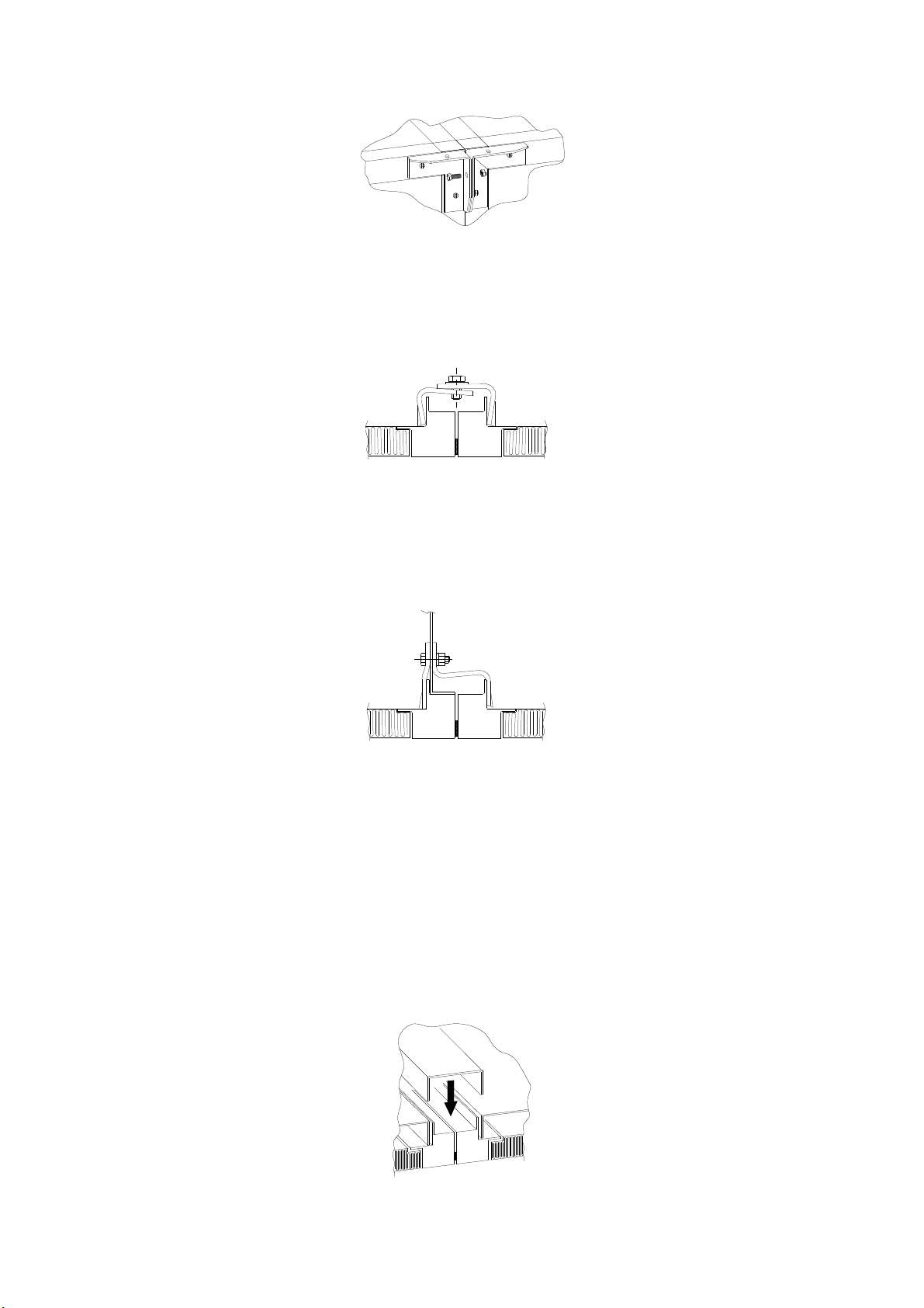
AIRSET und AIRSET X-Large der
Gerätegrößen 06.03 – 09.08 werden mit
außenliegenden Verbindungswinkel und
Sechskantschrauben M6 x 20 miteinander
verbunden (Bild 3).
Outdoor units have to be protected
against wind pressure on the construction
site depending on the expected wind
load. During installation interruptions and
installation which are done by Troges
Ges.m.b.H all protection arrangements
have to be made on site accordingly.
The height of the substructure has to be
selected in accordance to the local snow
condition.
According to EN 13779 the exhaust air of
outdoor units has to blown out vertical. The
outdoor air inlet has to be situated
minimum 3m above ground level.
Assembling
All delivery sections are marked with labels
which indicating the position of the
delivery section in the unit.
The connection material is inside of a unit
part with service door (mostly fan section).
This part is signed with the bill of enclosed
material.
The enclosed sealing tape must be glued
all round the unit frame between the
individual delivery sections prior to
assembly.
The individual delivery section must be
placed as closely together as possible
before joining them with the external
connection brackets or the internal
connection clamps.
To join the delivery sections together
external connection brackets or internal
connection clamps shall be used.
Depending on the frame type, weather
proofed unit or a hygienic unit the
adequate connection shall be used.
Use external brackets with hexagon-head
bolts M6 x 20 for AIRSE and AIRSET X-Large
with sizes from 06.03 to 09.08 (figure 3).
- 9 -
Page 10
T R O G E S AIRSET – Montage-, Betriebs- und Wartungsanleitung
AIRSET – Assembly, Operation and Maintenance Instructions
Bild 3
figure 3
AIRSET und AIRSTE X-Large der
Gerätegrößen 09.09 – 30.30 werden mit
innenliegenden Verbindungsklammern und
Sechskantschrauben M10 x 15 miteinander
verbunden (Bild 4).
Bild 4
figure 4
AIRSET und AIRSET X-Large der Baugrößen
09.09 – 30.30 werden bei Ventilatorteilen
spezielle innenliegende Klammern mit
Sechskantschraube M8 x 30 verwendet
(Bild 5).
Bild 5
figure 5
Um eine gleichmäßige und stabile Verbindung
herzustellen müssen die innenliegenden
Geräteklammern alle 300mm an den
Geräteprofilen angebracht und gut verschraubt
werden.
AIRSET Geräte in Hygieneausführung müssen
auf am Boden der Geräteinnenseite zusätzlich
mit speziellen U-Profilen verbunden werden.
Die Fugen an den Profilrändern muss
zusätzlich mit einem für Hygieneeinsatz
geeigneten Dichtmittel abgeschmiert werden
(Bild 6).
Bild 6
figure 6
Use internal clamps with hexagon-head
bolts M10 x 15 for AIRSET and AIRSET XLarge with sizes from 09.09 to 30.30 (figure
4).
To connect the fan section with any
adjoining section for AIRSET and AIRSET XLarge with sizes from 09.09 to 30.30 use
special internal clamps with hexagonhead bolts M8 x 30 (figure 5).
The internal unit clamps must be attached
to the unit profiles roughly every 300mm
and bolted on securely to ensure a solid
connection.
AIRSET units in hygienic version must be
additionally joined on the internal ground
with special U-profiles. The joints on the unit
floor need to bee sealed with special
silicone which is suitable for hygienic
conditions. (figure 6).
- 10 -
Page 11
T R O G E S AIRSET – Montage-, Betriebs- und Wartungsanleitung
AIRSET – Assembly, Operation and Maintenance Instructions
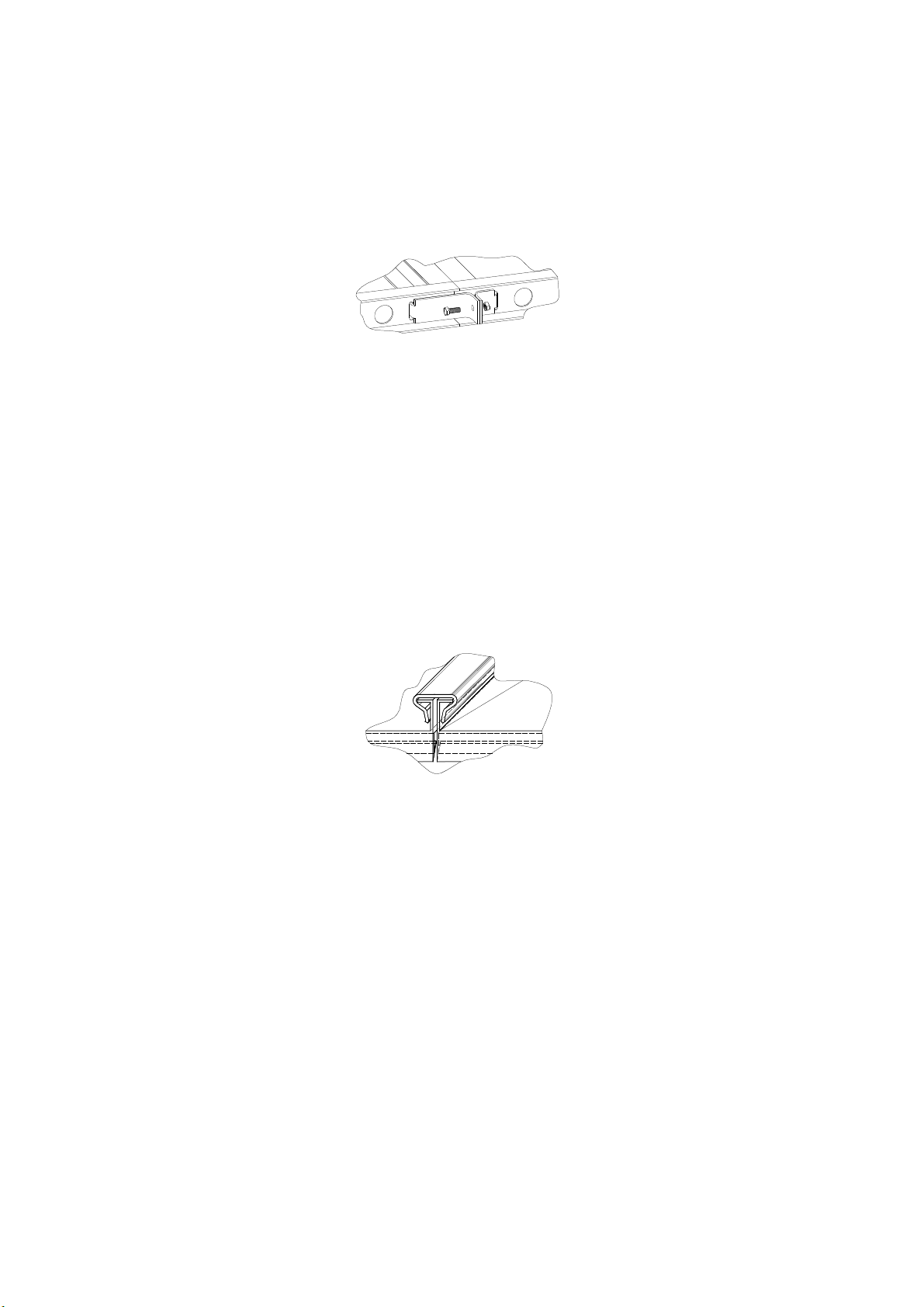
Grundrahmen sind mit eigenen Klammern zu
verbinden. Die Klammern werden in die, im
Grundrahmen eingefrästen Langlöcher
eingehängt und mit Sechskantschrauben
M10 x 35 verschraubt (Bild 7).
Bild 7
figure 7
Alle Verbindungsklammern bzw.
Verbindungswinkel dürfen nur so stark
angezogen werden, dass es zu keinen
Verformungen des Geräterahmens kommt.
Dachverbindungen bei AIRSET Geräten in
wetterfester Ausführung erfolgen mit dem
bewährten WEFA Treibschiebersystem. Die
Treibschieberlängen sind so ausgelegt, dass
bei der Montage die Treibschieber über die
Geräteteilungen hinausragen. Die Enden der
Treibschieber sind mit Silikon abzudichten
(Bild 8).
Bild 8
figure 8
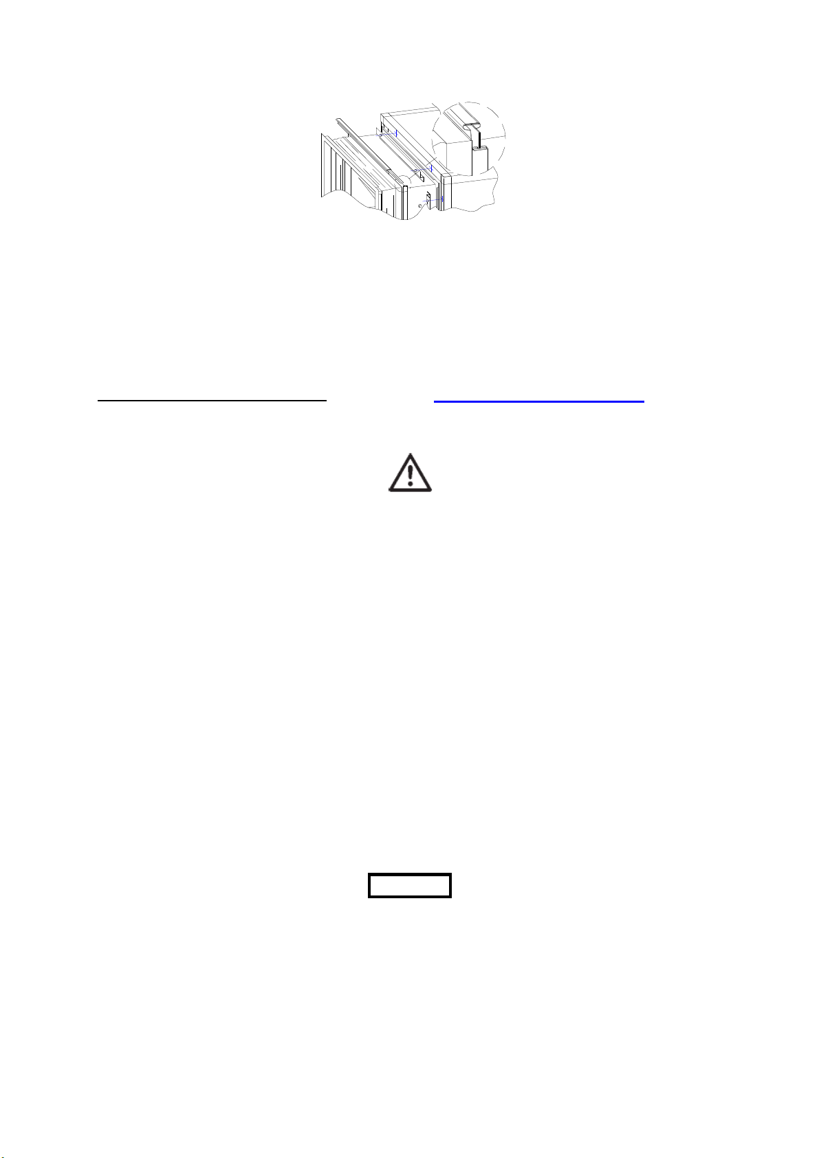
Segeltuchstutzen werden zum Anschluss an
das Luftkanalnetz, zur Vermeidung von
Körperschallübertragungen und zum Ausgleich
von Maßtoleranzen benötigt. Diese werden
standardmäßig bei allen AIRSET
Lüftungsgeräten mitgeliefert. Sie müssen
bauseitig thermisch und akustisch isoliert, und
mittels Potentialausgleichskabel überbrückt
werden.
Bei der Montage ist darauf zu achten, dass die
Segeltuchstutzen nicht gespannt eingebaut
werden. Die Verbindung zum Lüftungsgerät
erfolgt über Z-förmige Winkel bzw. unserem
bewehrten WEFA Treibschiebersystem
(Bild 9).
Base frames must be joined with special
clamps. The clamps are engaged in the
elongated holes milled into the basic
frame and secured with hexagon-head
bolts M10 x 35 (figure 7).
Do not overtighten the connection clamps
or connection brackets to avoid
deformation of the unit frame.
Roof connections of AIRSET units for
outdoor units are accomplished with the
proven WEFA drive slide system. Ensure
drive slide overlap on the roof joint. The
ends of the drive slides must be sealed with
silicone (figure 8)
Flexible canvases are required for the
connection of the AHU to the air duct
system in order to avoid the transmission of
solid-borne vibrations and to allow for
dimensional tolerances. These are supplied
as standard with all AIRSET air handling
units. On the construction site they must be
thermally and acoustically insulated and
bridged by means of potential
equalisation cable. On assembly ensure
that the flexible canvas are not stretched
on installation. For the connection
between flexible canvas and the air
handling unit use the Z shaped profiles
respectively our proven WEFA drive slide
system (figure 9).
- 11 -
Page 12
T R O G E S AIRSET – Montage-, Betriebs- und Wartungsanleitung
AIRSET – Assembly, Operation and Maintenance Instructions
Bild 9
figure 9
Nach Beendigung der Montagearbeiten
müssen alle Bedienungstüren auf ihre
Öffenbarkeit und Leichtgängigkeit überprüft,
und bei Bedarf nachgestellt werden.
Inbetriebnahme und Wartung
Wartungs- bzw. Reparaturarbeiten dürfen
nur bei ausgeschaltetem Gerät erfolgen.
Das Gerät ist über den Reparaturschalter
stromlos zu setzten und gegen
Wiedereinschalten zu sichern.
Bedienungstüren dürfen nur bei
Ventilatorstillstand geöffnet werden.
Bevor das Lüftungsgerät oder Teile
davon in Betrieb genommen werden,
muss das Lüftungsgerät vollständig
montiert und an das Kanalnetz
angeschlossen sein.
Tätigkeiten und Intervalle zur Wartung des
Lüftungsgerätes sind der VDMA 24186-1
Ausgabe 09\2002 bzw. ÖNORM H6021
Ausgabe 2003-09-01 zu entnehmen und
entsprechend zu dokumentieren (siehe
Anhang).
Bei Geräten in Hygieneausführung sind der
Umfang und die Intervalle der Kontrollen der
ÖNORM H6020 Ausgabe 2007-02-01 zu
entnehmen.
Beim Betreten des Lüftungsgerätes muss
darauf geachtet werden, dass die
Bodenpaneele nicht belastet werden. In
begehbaren Gerätegrößen sind hierfür
Wartungsstege eingebaut. Sind keine
Wartungsstege vorhanden müssen
Vorkehrungen getroffen werden, die Last
auf die Rahmenprofile zu verteilen.
Attention
Following completion of the assembly
work, check all operating doors to ensure
they open easily and adjust if required.
Start-up and maintenance
Maintenance and repairs may only be
performed with the unit switched off.
Turn off the unit by way of the repair
switch and lock to prevent switching on.
Operating doors may only be opened
with the fan turned off.
Before starting up the air handling unit or
parts thereof, the air handling unit must be
completely installed and connected to the
duct system.
Maintenance activities and intervals for
the air handling unit are described in
VDMA 24186 part 1, edition 09/2002 and
ÖNORM H6021 edition 2003-09-01 and
should be suitably documented (see
appendix)
The activities and intervals for air handling
units in hygienic version are described in
ÖNORM H-6020 edition 2007-02-01.
Take care that the floor panels don’t
get heavy load when you enter into the
air handling unit. In accessible units a
maintenance bar is situated. Don’t exist
any maintenance bar, make
arrangements to provide the floor
panels against too heavy loads.
- 12 -
Page 13
T R O G E S AIRSET – Montage-, Betriebs- und Wartungsanleitung
dk (mm)
F (N)
375 -
560
90 -
120
Riemendurchbiegekraft, die 1 Riemen
AIRSET – Assembly, Operation and Maintenance Instructions
Ventilatorteil
Inbetriebnahme
Transportsicherungen entfernen
Inbetriebnahmen nur mit
angeschlossenen Kanalsystem und
geschlossenen Revisionstüren - Gefahr
von Motorüberlastung!
Alle im Anlagensystem enthaltenen
Komponenten (Regelklappen, Absperrklappen,
Brandschutzklappen, Volumenstromregler,
usw.) sind auf Funktion zu prüfen und für den
Betrieb zu öffnen.
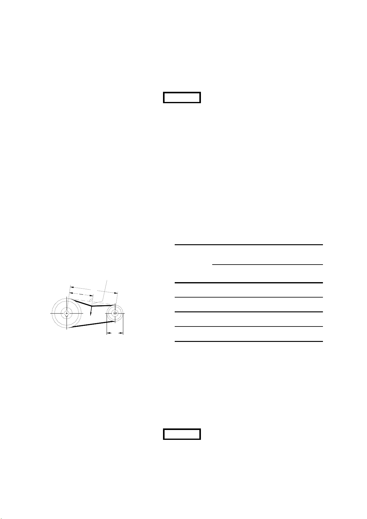
Die Keilriemen sind im Auslieferungszustand
nicht vorgespannt. Die Keilriemen müssen vor
der ersten Inbetriebnahme gespant werden!
Nach ca. 5 Betriebsstunden sind die
Keilriemen nach zu spannen und die
Riemenflucht ist zu überprüfen. Bei hohen
Ventilatordrehzahlen ist eine zusätzliche
Kontrolle der Keilriemenspannung nach ca. 4
Tagen erforderlich (Bild 10 und Tabelle 2).
16 mm Riemendurchbiegung
je 1 m Achsabstand
Caption 16mm belt deflection
per 1 m center distance of axes
A
A
2
F
d
k
Bild 10 Tabelle 2
figure 10 table 2
Bei Flachriemenantrieben ist die optimale
Riemenspannung je nach zu übertragender
Leistung bei einer Riemendehnung von 1,5 bis
2,5% erreicht.
Drehrichtung durch kurzes Einschalten des
Motors überprüfen
Die maximal zulässige Anlaufhäufigkeit
der Motoren darf nicht überschritten
werden.
Attention
Riemenprofil
SPZ 56 - 95 10 - 15
SPA 90 - 132 20 - 27
SPB 160 - 224 35 - 50
SPC 224 - 355 60 - 90
Attention
Fan section
Start-up:
Remove transport locks
Start up only with connected duct
system and closed maintenance doors
– risk of motor overload!
All system components (dampers, fire
dampers, air flow regulators, etc.) must be
checked and opened for run.
The V-belts are not pre-tensioned ex
factory. The V-belts must be tightened
before start-up and the tension and the
belt alignment need to be checked
approximately 5 hours of operation. In the
case of very high fan speeds an additional
check of the V-belt tension is required after
approx. 4 days (figure 10 and table 2).
pro 1m Achsabstand 16mm durchbiegt
kleine Scheibe Prüfkraft
100 - 140 15 - 20
140 - 200 28 - 35
236 - 315 50 - 65
For flat belt drives the optimal belt
alignment is reached when the belt
expansion is 1,5 to 2,5% of the belt length
(depends on the transmitted power.)
Switch on shortly motor power to check
the rotation direction.
Do not exceed the maximum
permissible start-up frequency of the
motors.
- 13 -
Page 14

T R O G E S AIRSET – Montage-, Betriebs- und Wartungsanleitung
AIRSET – Assembly, Operation and Maintenance Instructions
Messung des Motorstromes in allen 3
Phasen. Der Motorstrom darf den am
Typenschild angegebenen Nennstrom nicht
überschreiten. Messungen nur bei
geschlossenen Revisionstüren und
angeschlossenem Kanalsystem.
Für Motoren mit Kaltleiter ist ein
Kaltleiterauslösegerät, für Motoren mit
Thermokontakt ein Verriegelungsschütz und
für Motoren ohne Kaltleiter oder
Thermokontakt ist ein thermischer
Überstromschutzschalter anzuschließen.
Der elektrische Anschluss hat gemäß den ÖVE
– bzw. den jeweiligen nationalen und
internationalen Bestimmungen, EN60204 und
den Anschlussvorschriften der örtlichen EVU´s
zu erfolgen.
Bei Motoren mit mehreren Drehzahlen, darf
der Anlauf nur von der niedrigeren Drehzahl
auf die höhere Drehzahl erfolgen.
Bei auf Reparaturschalter verdrahteten
Motoren sind die Leitungsquerschnitte auf eine
max. Zuleitungslänge von 30m ausgelegt.
Wartung
• Ventilator auf Verschmutzung,
Beschädigung und Korrosion prüfen.
• Laufrad auf Unwucht prüfen.
• Ventilatorbefestigungsschrauben
nachziehen.
• Schwingungsdämpfer auf Funktion und
Beschädigung prüfen.
• Flexible Verbindung auf Dichtheit prüfen.
• Schutzgitter auf Funktion und festen Sitz
prüfen.
• Ventilatorlager auf Geräusch prüfen.
• Bei einem Lagertausch ist der gesamte
Riemenantrieb ebenfalls auszutauschen,
weil durch eingelaufen Riemenscheiben
bzw. unrundem Lauf des Keilriemens, die
Lagerlebensdauer erheblich verringert
wird.
• Ventilatorlager ggf. nachschmieren. Die
Nachschmierfristen und Fettmengen sind
der Wartungsanleitung des
Lagerherstellers zu entnehmen.
• Lithiumseifenfette sind mindergiftig
und somit gesundheitsgefährdend.
Unbedingt das Sicherheitsdatenblatt
des Herstellers beachten.
Measure the motor current in all 3 phases.
The motor current must not exceed the
rated current specified on the rating plate.
Perform measurement only with the
maintenance doors closed and the duct
system connected.
For motors with PTC-resistance it is
necessary to connect a PTC-resistance
triggering device, for motors with thermal
contact an interlocking contactor and for
motors without PTC-resistance or thermal
contact a thermal over current protection
switch must be connected.
The electrical connection must be
performed in accordance with the ÖVE or
the applicable national and international
regulations, EN60204 and the connection
regulations of the local EPSC’s.
On multi speed motors start-up may be
performed only from the lower speed to
the higher speed.
In the case of motors wired to repair
switches the cable cross sections are
designed for a cable length of 30 m.
Maintenance
• Inspect fan for dirt accumulation,
damage and corrosion.
• Check impeller for unbalance.
• Re-tighten fan mounting screws.
• Inspect vibration damper operation
and for damage.
• Inspect flexible connection for leaks.
• Check protective guard function and
tight seat.
• Check fan bearing for noise.
• If a bearing change is necessary
change also the whole belt drive,
because a defect belt drive can
reduce the life time of the bearing
considerably.
• Lubricate fan bearing if required. You
find the intervals and grease quantity
in the maintenance schedule of the
fan manufacturer.
• Lithium soap greases are mildly toxic
and consequently harmful to health.
Always observe the safety data sheet
of the manufacturer.
- 14 -
Page 15

T R O G E S AIRSET – Montage-, Betriebs- und Wartungsanleitung
AIRSET – Assembly, Operation and Maintenance Instructions
• Keilriemen auf korrekte Spannung
überprüfen (Tabelle 2).
• Keilriemenscheiben auf Flucht prüfen und
ggf. nachjustieren.
• Bei erforderlichem Riementausch muss
der gesamte Riemensatz ausgetauscht
werden. Bei den neu aufgelegten
Keilriemen ist auf Satzgleichheit zu
achten. Nach ca. 5 Betriebstunden sind
die Keilriemen nachzuspannen. Bei sehr
hohen Ventilatordrehzahlen ist eine
zusätzliche Kontrolle der
Keilriemenspannung nach ca. 4 Tagen
erforderlich.
• Bei einem Keilriementausch muss der
Achsabstand so weit verringert werden,
dass die Keilriemen ohne Zwang in die
Rillen der Riemenscheibe aufgelegt
werden kann. Eine gewaltsame Montage
der Keilriemen mit Montiereisen oder
Schraubenzieher ist unzulässig.
• Elektromotor auf Verschmutzung,
Beschädigung und Korrosion prüfen.
• Drehrichtung prüfen.
• Motorbefestigungsschrauben nachziehen.
• Motorlager auf Geräusch prüfen.
• Normmotore sind in der Regel mit
lebensdauergeschmierten Lagern
ausgeführt. Bei großen Baugrößen und
Sonderausführungen kommen auch nicht
lebensdauergeschmierte Lager zum
Einsatz. Die Nachschmierfristen und
Fettmengen sind der Wartungsanleitung
des Lagerherstellers zu entnehmen.
• Schutzeinrichtung auf Funktion prüfen.
• Funktionserhaltendes Reinigen um den
Kühlluftstrom zu gewährleisten.
• Speziell bei Motoreinhausungen mit
externer Kühlluftzufuhr ist darauf zu
achten, dass die Rohre frei von
Verschmutzungen und anderen
Fremdkörpern sind.
Luftfilter
Inbetriebnahme
Für die Erstinbetriebnahme der Lüftungsgeräte
empfehlen wir, die Taschenfilter kurzzeitig
durch Filtermatten zu ersetzen um die
Standzeit der Erstbestückung zu erhöhen.
Bei Hygieneanlagen werden die Filtereinsätze
lose in Originalverpackung geliefert. Diese
müssen vor Inbetriebnahme eingesetzt
werden.
• Check V-belts for correct tension
(table 2).
• Check V-belt pulley alignment and
adjust if required.
• If belts need to be replaced the entire
belt set must be replaced. Ensure the
newly fitted V-belts are from the same
set. After approximately 5 hours of
operation, tighten up the V-belts. In
case of very high fan speeds an
additional check of the V-belt tension
is required after approximately 4 days.
• Don’t force the V-belt over the pulleys.
First reduce the axes distance and
then mount the V-belt. A forcible
montage with tyre tool or screw drivers
is not allowed.
• Check electric motor for dirt
accumulation, damage and
corrosion.
• Check rotation direction.
• Re-tighten motor mounting bolts.
• Check motor bearings for noise.
• Standard motors are generally
equipped with permanently
lubricated bearings. In the case of
special versions, bearings which need
to be lubricated may be used. The relubricating intervals and grease
quantities are specified in the
maintenance instructions of the motor
manufacturer.
• Check protective device function.
• Clean to ensure the cooling air flow
required to maintain operation.
• In case of motor housing with external
cooling air supply, check the tubes
agains dirt accumulation and other
foraign materials.
Air filter
Start-up:
For initial start-up of the air handling units
we recommend to temporarily replace the
bag filters with filter mats in order to
increase the durability of the initial
equipment.
In hygienic units the air filters will be
delivered separately in original packaging.
- 15 -
Page 16

T R O G E S AIRSET – Montage-, Betriebs- und Wartungsanleitung
AIRSET – Assembly, Operation and Maintenance Instructions
Die Taschen der untersten Filterreihe dürfen
nicht am Geräteboden aufliegen. Die Filter
müssen mit stehenden Taschen eingebaut
werden.
Beim Filtertausch ist eine Schutzmaske über
Nase und Mund zu tragen.
Wartung
• Kontrolle der Druckdifferenz.
• Bei erreichen der Enddruckdifferenz sind
die Taschenfilterzellen gegen Filterzellen
gleicher Güteklasse zu tauschen. Die
Enddruckdifferenz ist bei den
verschiedenen Filterklassen
unterschiedlich. Bitte entnehmen Sie die
empfohlene Enddruckdifferenz der
technischen Dokumentation bzw. dem
Filtertypenschild. Eingerissene
Filtertaschen sind unbrauchbar.
• Filterauflage auf Dichtheit prüfen
• Filtergehäuse reinigen.
• Bei Hygieneanlagen muss die
Filterkammer nach jedem Filtertausch
gereinigt werden.
• Bei Hygieneanlagen soll der Filter inkl.
Dichtung getauscht werden.
Erhitzerteil
Inbetriebnahme
Die Wärmetauscher müssen im
Gegenstromprinzip (Wasserdurchflussrichtung
entgegen der Luftrichtung im Gerät)
angeschlossen werden, ansonsten erheblicher
Leistungsverlust.
Die bauseitigen Anschlussleitungen müssen so
geführt und trennbar sein, dass der Ausbau
des Registers ohne aufwendige
Demontagearbeiten durchgeführt werden
kann.
Beim Anschluss der Wärmetauscher muss
an den Rohrstutzen mit geeigneten Mitteln
(z.B. Rohrzange) gegengehalten werden
um Beschädigungen zu vermeiden.
Die Rohrleitungen müssen so ausgeführt
werden, dass Schwingungen, mechanische
Spannungen und das Eigengewicht der
Rohrleitungen nicht auf das Lüftungsgerät
übertragen werden.
Register müssen beim Befüllen vollständig
Entlüftet werden. Das System sollte, von der
tiefsten Stelle aus, langsam befüllt werden um
Luftpolster im System zu vermeiden.
Attention
The filter bags of the lowest filter line may
not lie on the floor panel. The filters have to
be installed with vertical bags. A
protection mask over mouth and nose
must be used during change of filters.
Maintenance
• Check the pressure differential.
• On reaching the final pressure drop,
replace the bag filter cells with filter
cells of the same quality category and
bag lengh. Filters of different quality
classes have different final pressure
drop. Look on the technical
documentation to find the right final
pressure drop. Torn filter pockets have
to be replaced.
• Check filter contact for leaks.
• Clean filter housing.
• With hygienic units the filter housing
have to be cleaned after each filter
change.
• With hygienic units filter and sealing
should be changed.
Heater
Start-up:
The heat exchangers must be installed in
accordance with the counter flow
principle (water flow direction opposite to
the air direction in the unit) to prevent
considerable loss of performance.
The connection lines furnished on site must
be routed and disconnectable so that
removal of the coil can be performed
without major disassembly operations.
When connecting the heat exchangers
the pipe spigots must be held up with
suitable equipment (for instance pipe
wrench) in order to avoid damage.
The pipes must be designed so that
vibrations, mechanical stresses and the
weight of the piping are not transmitted to
the air handling unit.
The coils have to be completely ventilated
when the system gets filled. The system
should be filled from the deepest point to
provide the system against air pockets.
- 16 -
Page 17

T R O G E S AIRSET – Montage-, Betriebs- und Wartungsanleitung
AIRSET – Assembly, Operation and Maintenance Instructions
In der Zuleitung soll bauseitig ein Filter bzw.
Schmutzfänger eingebaut werden.
Es müssen bauseitig Entlüftungs- und
Entleerungsmöglichkeiten vorgesehen werden.
Bei Anlagen mit Außenluftbetrieb müssen
geeignete Frostschutzeinrichtungen
vorgesehen werden (Frostschutzthermostat).
Der Zusatz von Frostschutzmitteln führt zu
einer Leistungsminderung, wenn das
Froschschutzmittel bei der Auslegung nicht
berücksichtigt wurde.
Beim Stillsetzten von Wärmetauschern ist das
Restwasser mittels Druckluft aus den
Registern zu entfernen. (Korrosion,
Einfriergefahr)
Cu/Al – Register dürfen mit einer max.
Vorlauftemperatur von 110 °C bei einem
max. Betriebsdruck von 16 bar betrieben
werden. Bei Registern aus anderen
Werkstoffen Betriebszustände gemäß
Datenblatt.
Wartung
• Register auf luftseitige Verschmutzung,
Beschädigung und Korrosion prüfen
• Reinigung der Registerlamellen z.B.:
mittels Druckluft bei Cu/Al-Registern
entgegen Luftrichtung. Bei
stahl/verzinkten Register kann auch mit
Hilfe von Dampfstrahlgeräten gereinigt
werden.
• Kontrolle der Anschlüsse und
Verschraubungen auf Dichtheit.
• Register entlüften.
• Wenn eine Frostschutzeinrichtung
vorhanden ist, diese periodisch auf
dessen Funktion
• Bei Wartungs- und
Reinigungsarbeiten auf die Registerlammellen achten. Schnittgefahr!
Attention
Filters or dirt traps have to be situated at
the inlet pipe.
Ventilation and drainage features must be
provided on site.
Suitable frost protection installations must
be provided for outside air operations (frost
protection thermostat).
Anti freezing additive reduce the
efficiency and need to be taken into
account when the heater is calculated.
When heat exchangers are shut down it is
necessary to remove the residual water
with compressed air from the coils
(corrosion, freezing hazard).
Cu/Al coils may be operated with a
maximum flow temperature of 110 °C
with a maximum operating pressure of
16 bar. In the case of coils made of
other materials refer to the data sheet
with regard to the operating conditions.
Maintenance
• Inspect coil and fins for dirt
accumulation on the air side, damage
and corrosion
• Clean the coil elements for instance
as follows: With compressed air in the
case of Cu/Al coils against the
direction of the air flow. In the case of
steel/galvanised coils cleaning can
also be performed with the help of
steam cleaners.
• Check the connections and screw
connections
• Bleed coil.
• If an anti freezing device exists, check
periodically the function.
• During maintenance and cleaning
operations, beware of the fins which
may cause injuries!
- 17 -
Page 18

T R O G E S AIRSET – Montage-, Betriebs- und Wartungsanleitung
AIRSET – Assembly, Operation and Maintenance Instructions
Elektroerhitzer
Inbetriebnahme
Den elektrischen Anschluss des
Lüftungsgerätes darf nur eine
Elektrofachkraft vornehmen.
Der elektrische Anschluss hat gemäß den ÖVE
– bzw. den jeweiligen nationalen und
internationalen Bestimmungen, EN60204 und
den Anschlussvorschriften des örtlichen EVU’s
zu erfolgen.
Aus Sicherheitsgründen muss sichergestellt
werden, dass bei Ausfall des Luftstromes der
Elektroerhitzer abgeschaltet wird (z.B.
Strömungswächter, Überhitzungswächter,
Verriegelungsschütz).
Bei hoher Oberflächentemperatur muss
darauf geachtet werden, dass keine
benachbarten Bauteile Schaden nehmen
können.
Es ist darauf zu achten, dass keine
Zunderteilchen über den Elektroerhitzer
transportiert werden können.
Wartung
• Register auf Zunderansatz und Korrosion
prüfen.
• Sicherheitsthermostat und Temperaturwächter auf Funktion prüfen.
Attention
Kühlerteil
Inbetriebnahme
Für den Anschluss der Luftkühler gelten im
wesentlichen die selben Vorgaben wir für die
Lufterhitzer.
An den Ablauf der Kondensatwanne muss ein
Siphon luftdicht angeschlossen werden.
Jeder Kondensatablauf muss mit einem
eigenen Siphon ausgestattet sein.
Bei Hygieneanlagen ist ein Siphon mit
durchsichtigem Standrohr zu verwenden, um
jederzeit den Füllstand des Siphons
kontrollieren zu können.
Das Wasser aus dem Siphon muss frei
ablaufen können.
Electric heater
Start-up:
Only a certified electrician is allowed to
connect the electric power to the AHU.
The electrical connection must be
performed in accordance with ÖVE – or
the applicable national regulations,
EN60204 and the connection regulations of
the local EPSC’s.
For safety reasons it must be ensured that
the electric heater is switched off in case
the air flow fails (for instance flow control
unit, overheating protection switch,
interlocking contactor).
In the event of high surface
temperature it must be ensured that no
adjacent components can be
damaged.
Ensure that no scale particles are
transported across the electric heater.
Maintenance
• Check coil for traces of scale and
corrosion.
• Check safety thermostat and
temperature protection switch for
proper operation.
Air cooler
Start-up:
Essentially the same applies to the
connection of the air cooler as to the air
heater.
The condensate tube of the air cooler
must be connected air tight to the drain
by way of a siphon.
Every condensate drain must be equipped
with its own siphon.
With hygienic AHU’s the siphon should be
equipped with a transparent stand pipe in
order to be able to check the filling level of
the siphon.
The water must be able to drain freely from
the siphon.
- 18 -
Page 19
T R O G E S AIRSET – Montage-, Betriebs- und Wartungsanleitung
2
∆
AIRSET – Assembly, Operation and Maintenance Instructions
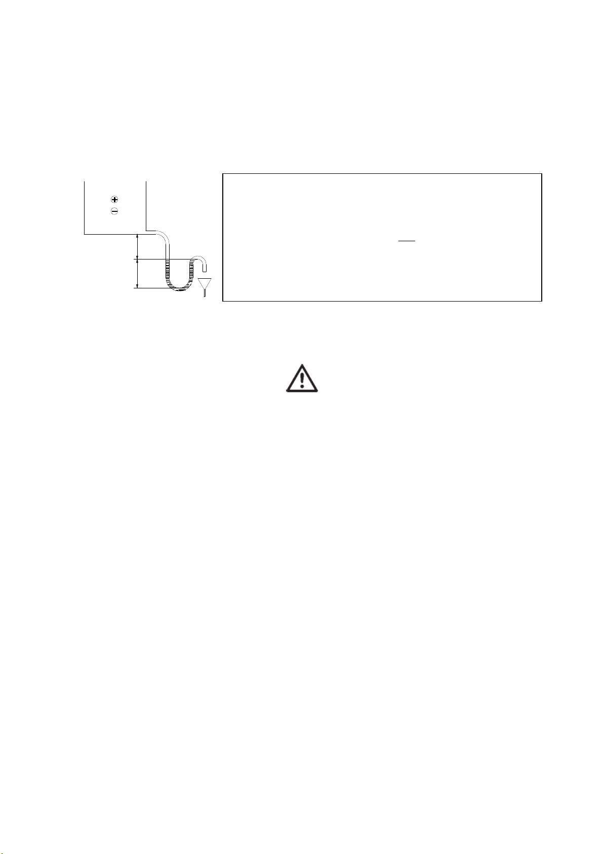
Der Sifon muss immer mit Wasser gefüllt sein.
Die Sifonhöhen müssen entsprechend dem
Geräteinnendruck ausgelegt werden (Bild 11
und Tabelle 3).
1
2
H H
Bei Überdruck im Gerät: H1 = 20mm
Over pressure in the unit: H2 = ∆P + 20mm
Bei Unterdruck im Gerät: H1 = ∆P + 20mm
Under pressure in the unit: H2 =
∆P = Über- od Unterdruck im Gerät in mm WS (Werte immer positiv einsetzten)
∆P = Over or under pressure in the unit in mm WC (always enter positive)
10 Pa = 1 mm WS (Wassersäule)
10 Pa = 1 mm WC (water column)
Bild 11 Tabelle 3
figure 11 table 3
Bei Verwendung von Frostschutzmitteln
sind die Sicherheitshinweise des
Herstellers unbedingt einzuhalten.
Frostschutzmittel sind gesundheitsgefährdend!
Tropfenabscheider erbringen erst nach einer
Anlaufzeit von ca. 4 Wochen ihre vollständige
Wirkung.
Bei nicht völliger Tropfenabscheidung ist die
richtige Einbaulage der Tropfenabscheider zu
kontrollieren. Eventuell muss die
Luftgeschwindigkeit über den
Tropfenabscheider gemessen werden.
Wartung
• Luftkühler auf luftseitige Verschmutzung,
Beschädigung und Korrosion prüfen
• Reinigung der Registerlamellen z.B.:
mittels Druckluft bei Cu/Al-Registern
entgegen Luftrichtung. Bei
stahl/verzinkten Register kann auch mit
Hilfe von Dampfstrahlgeräten gereinigt
werden.
• Kontrolle der Anschlüsse bzw.
Verschraubungen auf Dichtheit.
• Register entlüften.
• Kondensatablauf prüfen und reinigen.
The siphon must always be filled with
water.
The siphon levels must be designed in
accordance with the internal unit pressure
(figure 11 and table 3).
P
+ 20mm
When using anti-freeze agents it is
indispensable to observe the safety
instructions of the manufacturer. Antifreeze agents are harmful to health!
The drop eliminator reaches its maximum
efficiency only after a short running-in
phase of approx. 4 weeks
When the drops are not completely
separated, check the right installation
position of the drop eliminator. It may be
necessary to check the air velocity over
the drop eliminator surface.
Maintenance
• Check air coolers for dirt
accumulation on the air side, damage
and corrosion.
• Cleaning the coil elements for
instance: With compressed air in the
case of Cu/Al coils against the air
flow. In the case of steel/galvanised
coils it is also possible to clean with the
help of steam cleaners.
• Check the connections and screw
connections.
• Bleed register.
• Check and clean condensate drain.
- 19 -
Page 20

T R O G E S AIRSET – Montage-, Betriebs- und Wartungsanleitung
AIRSET – Assembly, Operation and Maintenance Instructions
• Siphon kontrollieren und bei Bedarf
nachfüllen.
• Tropfenabscheiderlamellen auf
Verschmutzung prüfen und bei Bedarf
reinigen.
• Bei Wartungs- und Reinigungs-
arbeiten auf die Registerlammellen
achten. Schnittgefahr!
Direktverdampfer / Kondensator
Inbetriebnahme
Der Kälteanschluss darf ausschließlich von
einer zugelassenen Fachfirma für Kältetechnik
vorgenommen werden.
Um die Leistungsdaten des Registers
erreichen zu können, darf nur das Kältemittel
verwendet werden, welches der Auslegung zu
Grunde liegt (R407C, R410A...).
Beim Anschluss muss die Schutzgasfüllung
vorhanden sein.
Vor- und Rücklauf auf richtige Schaltung
prüfen (Gegenstromprinzip).
System auf Dichtheit prüfen
Das Kältemittel darf nicht in die Umwelt
entweichen.
Sicherheitseinrichtungen auf Funktion prüfen.
Wartung
• Wärmetauscher auf luftseitige
Verschmutzung, Beschädigung und
Korrosion prüfen.
• Reinigung der Registerlamellen z.B.:
mittels Druckluft bei Cu/Al-Registern
entgegen Luftrichtung.
• Kondensatablauf prüfen und reinigen.
• Siphon kontrollieren und bei Bedarf
nachfüllen.
• Tropfenabscheiderlamellen auf
Verschmutzung prüfen und bei Bedarf
reinigen.
• Funktionsprüfung aller Kältekomponenten.
• Die Wartung an den
Kältemittelanschlüssen darf nur von einer
zugelassenen Fachfirma für Kältetechnik
vorgenommen werden.
• Bei Wartungs- und
Reinigungsarbeiten auf die
Registerlammellen achten.
Schnittgefahr!
• Check siphon and replenish if
required.
• Check drop eleminator elements for
dirt accumulation and clean if
required.
• Pay attention to the coil elements
during maintenance and cleaning
work to avoid cutting injuries!
Evapurator / Condenser
Start-up:
The refrigerant connection must be
performed by an approved specialist
company.
In order to achieve the performance data
of the coil use only the refrigerant used as
a base for the design (R407C, R410A...).
When the coil is connected it should be
pressurized with protective gas.
Check the right connection of medium
inlet and outlet (counter flow principle).
Check the system tightness.
The refrigerant must not escape into the
environment.
Check the protective device function.
Maintenance
• Check exchanger for dirt
accumulation on the air side, damage
and corrosion.
• Clean the coil elements for instance:
By means of compressed air in the
case of Cu/Al registers against the air
flow.
• Check and clean condensate drain.
• Check siphon and replenish if
required.
• Check drop eliminator elements for
dirt accumulation and clean if
required.
• Check all refrigent components of
function.
• Maintenance on the refrigerant
connections may only be performed
by an approved specialist company.
• When carrying out maintenance and
cleaning operations pay attention to
the coil elements to avoid cutting
injuries!
- 20 -
Page 21

T R O G E S AIRSET – Montage-, Betriebs- und Wartungsanleitung
AIRSET – Assembly, Operation and Maintenance Instructions
Plattenwärmetauscher
Inbetriebnahme
Die Funktion des Plattentauschers ist rein
statisch und bedarf daher keiner besonderen
Inbetriebnahme.
Die Kondensatwannen des Plattentauschers
sind über Siphons an Abläufe anzuschließen.
Für die Auslegung der Siphonhöhen gilt das
Gleiche wie bei den Lüftkühlern.
Bei einer vorhandenen Bypassregelung des
Plattentauschers zum Schutz vor Einfrieren
muss die Funktion der Bypassklappe
überprüft werden.
Wartung
• Plattentauscher auf luftseitige
Verschmutzung prüfen.
• Trockener Staub, Flusen o. ä. mit einem
weichen Besen oder Staubsauger
reinigen.
• Fetthaltige Ablagerungen (z.B.: von
Küchenabluft) mit heißem Wasser oder
fettlösenden Reinigungsmitteln entfernen.
Bei Einsatz von chemischen
Spezialreinigern ist vorher mit uns
Rücksprache zu halten.
• Kondensatabläufe prüfen und reinigen.
• Siphon kontrollieren und bei Bedarf
nachfüllen.
• Bypassklappe auf Funktion prüfen.
• Bypassklappe mit Druckluft oder
Staubsauger reinigen.
• Bei Wartungs- und Reinigungs-
arbeiten auf die Tauscherplatten
achten. Schnittgefahr!
Rotationswärmetauscher
Inbetriebnahme
Speichermasse auf Laufruhe und Zentrierung
überprüfen.
Drehrichtung überprüfen.
Position der Spühlkammer kontrollieren.
Spannung des Antriebsriemens prüfen,
gegebenenfalls nachspannen.
Plate heat exchanger
Start-up:
The operation of the plate heat
exchanger is purely static and
consequently requires no special start-up.
The condensate tubes of the plate heat
exchanger must be connected to drains
by way of siphons. For the design of the
siphon levels the same applies as for the
air coolers.
A bypass control must protect the plate
heat exchanger against freezing. Freezing
limits in accordance with the data sheet.
Maintenance
• Check plate heat exchanger for dirt
accumulation on the air side.
• Clean dry dust, lint, etc., with a soft
brush or vacuum cleaner.
• Remove greasy deposits (for instance
due to kitchen air) with hot water or
degreasing cleaning agents. When
using special chemical cleaners,
please consult us beforehand.
• Check and clean condensate drains.
• Check siphon and replenish if
required.
• Check bypass damper operation.
• Clean bypass flap with compressed air
or vacuum cleaner.
• Pay attention to the exchanger plates
to avoid cutting injuries during
maintenance and cleaning
operations!
Rotary heat exchanger
Start-up:
Check the wheel for smooth running and
balancing.
Check the direction of rotation.
Check the position of the cleaning
section.
Check the tension of the belt drive, and
adjust the tension if required.
- 21 -
Page 22
T R O G E S AIRSET – Montage-, Betriebs- und Wartungsanleitung
AIRSET – Assembly, Operation and Maintenance Instructions
Sitz der umlaufenden Dichtelemente
kontrollieren, gegebenenfalls nachstellen.
Bei vorhandener Bypassregelung die
Bypassklappen auf Funktion prüfen.
Wartung
• Speichermasse auf luftseitige
Verschmutzung, Beschädigung und
Korrosion prüfen.
• Regelmäßige Reinigung mit Pressluft oder
Hochdruckgeräten (Reinigungsmittel nur
Wasser ohne chemische Zusätze).
• Spannung des Antriebskeilriemens
regelmäßig prüfen und ggf. nachspannen.
• Dichtelemente auf Funktion prüfen.
• Speichermasse auf Laufruhe und
Zentrierung überprüfen.
• Mess- und Steuereinrichtungen auf
Funktion prüfen.
• Motorflucht kontrollieren.
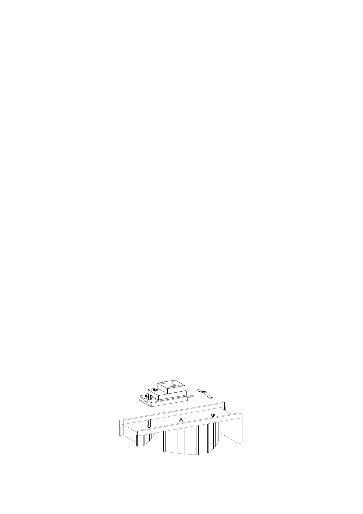
Jalousieklappen
Montage des Stellantriebes
• Den Klappenantrieb auf die Klappenachse
aufstecken.
• Die Muttern am V-Bügel von Hand leicht
anziehen
• Die Verdrehsicherung anpassen und
befestigen.
• Die Klappe in die Zu-Stellung bringen.
• Das Getriebe durch Fingerdruck auf die
Entriegelungstaste ausrasten und den
Klemmbock einen Teilstrich vor die ZuStellung drehen und anschließend wieder
einrasten lassen.
• Den Stellmotor auf 90° zur Klappenachse
ausrichten und die Muttern am V-Bügel
fest anziehen.
Check the seat of the sealing elements
and adjust them if required.
If a bypass control exists check the bypass
damper function.
Maintenance
• Inspect wheel for dirt accumulation on
the air side, damage and corrosion.
• Regularly clean with compressed air or
high-pressure units (use only water
without chemical additives).
• Regularly check the tension of the belt
drive and adjust the tension if
required.
• Check sealing element function.
• Check the wheel for smooth running
and balancing.
• Check measuring and control
installations for proper operation.
• Check the motor alignment.
Dampers
Installation of damper actuator
• Fit the damper actuator on the
damper shaft.
• Manually tighten the nuts on the V-
frame.
• Adapt and secure the rotation
protection.
• Place the damper in the closed
position.
• Disengage the gear by pressing the
unlocking button and turn the
clamping pedestal one division in front
of the closed position and allow to reengage.
• Align the actuator 90° relative to the
damper shaft and tighten the nuts on
the V-frame.
Bild 12
figure 12
- 22 -
Page 23

T R O G E S AIRSET – Montage-, Betriebs- und Wartungsanleitung
AIRSET – Assembly, Operation and Maintenance Instructions
Inbetriebnahme
Bei gekoppelten Klappen ist das
Verbindungsgestänge zu kontrollieren.
Verbindungsgestänge muss so justiert werden,
dass ein Öffnungswinkel von 90°erreicht wird.
Auf richtige Anschlussspannung des
Stellantriebes achten. Spannung 24V
bzw. 230V.
Bei der Funktionsprüfung des Stellantriebes
darauf achten, dass die Endlage erreicht wird.
Wartung
• Jalousieklappen auf Verschmutzung,
Beschädigung und Korrosion prüfen.
• Gestänge, Gelenke und Zahnräder auf
festen Sitz und Funktion prüfen.
• Jalousieklappe durch Ausblasen mittels
Druckluft reinigen.
• Klappenstellmotore auf richtigen Aufbau
und Endlage prüfen und eventuell
nachjustieren.
Attention
Schalldämpfer
Wartung
• Schalldämmkulissen auf Beschädigung
prüfen.
• Kulissen auf Verschmutzung prüfen und
gegebenenfalls mit einem Staubsauger
reinigen.
• Bei Geräten in Hygieneausführung sind
die Schalldämmkulissen seitlich
ausziehbar.
Düsenbefeuchter
Inbetriebnahme
Falls kein Grundrahmen unter dem
Lüftwäscher vorgesehen ist, muss darauf
geachtet werden, dass eine vollflächige, 100 %
ebene Auflage vorhanden ist.
Vor der Inbetriebnahme muss sichergestellt
sein, dass die am Typenschild angegebenen
Maximalwerte (Unter- bzw. Überdruck,
Temperatur und Luftmenge...) nicht
überschritten werden.
Start-up:
With connected dampers check the
connection rods.
Adjust the connection rods, in order
to an opening angle of 90°.
Ensure proper connection voltage.
Voltage 24V or 230V
Check function of actuator and
ensure that the final position can be
reached.
Maintenance
• Check dampers for dirt accumulation,
damage and corrosion.
• Check linkage, joints and gears for
proper seating and operation.
• Clean damper by blowing with
compressed air.
• Check damper actuators for proper
installation and final position and readjust if necessary.
Silencers:
Maintenance
• Check silencer slot for damage.
• Check silencers for dirt accumulation
and cleaning if necessary.
• With units in hygienic version the
silencer splitters can be pulled out
laterally.
Air washer
Start-up:
If no base frame is provided under the
humidifier, ensure that the unit is 100 % in
contact with a level surface.
Prior to start-up ensure that the maximum
values (under-/over-pressure, temperature
and air flow rate...) specified on the rating
plate are not exceeded.
- 23 -
Page 24

T R O G E S AIRSET – Montage-, Betriebs- und Wartungsanleitung
AIRSET – Assembly, Operation and Maintenance Instructions
Das Schwimmerventil ist so einzustellen, dass
es bei einem Wasserstand von 5-10mm
unterhalb des Überlaufes schließt. Der
Wasserstand im Luftwäscher ist richtig, wenn
die Gleichrichter- und Tropfenabscheiderlamellen 80-100mm tief im Wasser
stehen.
Die vorhandenen Anschlüsse für
Frischwasserzufuhr, Ab- und Überlauf und evtl.
Abschlämmleitung sind in der vorgesehenen
Nennweite ohne Einschnürung, aber mit
Gefälle, mit den entsprechenden
Rohrleitungen zu verbinden.
Bei bauseitigem Siphon gelten die gleichen
Vorgaben wie beim Lüftkühler.
Es ist für gleichmäßige Luftan- bzw.
Abströmung zu sorgen.
Die Wäscherpumpe darf auf keinen Fall
trocken laufen.
Das Wannenwasser muss für den
Pumpenanlauf unbedingt sauber und von
Bauschmutz und Staub gereinigt sein.
Auf Motordrehrichtung achten. Vor
Inbetriebnahme mit Phasendrehrichtungsanzeiger prüfen.
Den Saugkorb in der Wäscherwanne auf
richtigen und festen Sitz prüfen.
Die Stromaufnahme des Pumpenmotors ist
bei Inbetriebnahme zu messen. Sie darf
den an Typenschild angegebenen
Nennstrom nicht überschreiten.
Nach der Inbetriebnahme ist die Funktion aller
Düsen durch das Schauglas zu überprüfen.
Der Düsendruck sollte ca. 2,5 bar betragen.
Die Wasserabscheiderlamellen erreichen ihre
höchste Wirksamkeit erst nach einer
Einlaufphase von ca. 4 Wochen. Bei
anfänglichem Wasserdurchschlag kann diese
verkürzt werden, indem kurzzeitig normales
Stadtwasser anstelle von demineralisiertem
Wasser eingespeist wird. In dieser Einlaufzeit
sollte die Abschlämmleitung verschlossen
bleiben.
Attention
Attention
Set the float valve so that it closes at a
water level of 5 – 10 mm below the
overflow. The water level in the humidifier is
correct when the rectifier and drop
eliminator elements are 80-100mm deep
immersed in water.
Connect the existing connections for fresh
water supply, drain and overflow and
possible sludge discharge lines in the
specified nominal diameter without
constrictions but with an incline to the
appropriate pipes.
The same specifications as for the air
cooler apply to siphons provided on site.
Even air inflow and discharge must be
ensured.
The air washer pump must not run dry
under any circumstances.
For starting the pump, the tub water must
be absolutely clean and dirt and dust
removed.
Ensure the proper direction of rotation of
the motor. Prior to start-up, check with
phase direction of rotation indicator.
Check the suction cage in the air washer
tub for proper and secure seat.
Measure the power consumption of the
pump motor on start-up. It must not
exceed the rated current specified on
the rating plate.
Following start-up, check the operation of
all nozzles through the sight glass.
Water pressure at the nozzles should be
approximately 2,5 bar.
The drop eliminator elements reach their
maximum efficiency only after a short
running-in phase. Initial water penetration
can be shortened by briefly supplying
normal municipal water instead of
demineralised water. The sludge discharge
line should be kept shut during this runningin phase.
- 24 -
Page 25

T R O G E S AIRSET – Montage-, Betriebs- und Wartungsanleitung
AIRSET – Assembly, Operation and Maintenance Instructions
Die Abschlämmwassermenge muss so
eingestellt werden, dass sich die
Wasserqualität im Betrieb nicht übergebühr
verschlechtert. Dass kann entweder über eine
Abschlämmeinrichtung (z.B.: Kugelhahn)
erfolgen, oder über das Schwimmerventil,
welches so eingestellt wird, dass ständig eine
gewisse Wassermenge über den Überlauf
abläuft.
Wartung
• Die Wartungsintervalle richten sich nach
der Anzahl der Betriebsstunden und nach
der Luft- und Wasserqualität.
• Für einen hygienischen Betrieb ist ein
häufiges (evtl. wöchentlich) Ablassen des
Wannenwassers notwendig. Dabei ist der
Luftwäscher gründlich auszuspritzen und
zu säubern.
• Reinigen der in der Wasserwanne
befindlichen Filter, Siebe und
Schmutzfänger.
• Bei Anzeigen eines erhöhten Druckabfalls
an den Düsen (Sollwert ca. 2,5 bar) sind
die Wasserwege (inkl. Pumpenlaufrad,
Saugkorb, usw.) auf Sauberkeit und
Freiheit zu kontrollieren und von
Schmutzablagerungen zu säubern
• Sprühdüsen und Tropfenabscheider von
angesetztem Kalk reinigen. Dies kann mit
Hilfe von Kalklösern erfolgen, wobei die
Reinigungs- und Gebrauchsvorschriften
genau zu beachten sind.
• Gleichrichter- und Tropfenabscheiderpakete können mit einem
Hochdruckreiniger gereinigt werden. Für
in der Tiefe sitzende Verschmutzung ist
es notwendig die Lamellen auszubauen
und einzeln zu reinigen.
• Bei allen Arbeiten ist sicherzustellen,
dass vor einem Einstieg in das
Wäscherinnere der Betrieb der
Pumpen mit absoluter Sicherheit
verhindert wird.
ERSTICKUNGSGEFAHR !
• Bei Verwendung von elektrischen
Geräten sind unbedingt die für
feuchte Umgebung notwendigen
Maßnahmen zu berücksichtigen.
The sludge water discharge quantity must
be adjusted so that the water quality does
not deteriorate excessively during
operation. This can be performed either by
a sludge discharge device (for instance
ball valve) or by way of the float valve
which must be set so that a certain water
quantity continuously drains off by way of
the overflow.
Maintenance
• The maintenance intervals depend on
the number of operating hours and
the air and water qualities.
• Frequent (possibly weekly) drainage of
the tub water is necessary for hygienic
operation. The air washer must be
thoroughly rinsed out and cleaned.
• The filters, screens and dirt traps
located in the water tub must be
cleaned.
• Upon indication of an increased
pressure drop on the nozzles (nominal
value approximately 2.5 bar), check
the waterways (including pump
impeller, suction cage, etc.) for
cleanness and ease of operation and
remove possible dirt accumulation.
• Remove lime deposits from spray
nozzles and drop eleminator elements.
This can be performed by means of
descaling agents while the cleaning
and instructions for use must be
observed exactly.
• Rectifier and drop eliminator
packages can be cleaned with a
high-pressure cleaner. Deep-seated
dirt can be cleaned by removing the
elements and cleaning them
individually.
• During all work ensure that pump
operation is definitifly prevented prior
to entering the interior of the air
washer.
DANGER OF SUFFOCATION!
• When using electrical equipment it is
essential to take into account the
measures necessary for operating in
moist environment.
- 25 -
Page 26

T R O G E S AIRSET – Montage-, Betriebs- und Wartungsanleitung
AIRSET – Assembly, Operation and Maintenance Instructions
Verdunstungsbefeuchter
Inbetriebnahme
Die Inbetriebnahme und der elektrische
Anschluss ist der separat beiliegenden
Betriebsanleitung des Befeuchterherstellers zu
entnehmen.
Wartung
• Die Wartungsintervalle sind von der Luftund Wasserqualität abhängig. Wir
empfehlen jedoch mindestens
vierteljährlich eine Wartung vorzunehmen.
• Prüfen, ob die Kontaktkörperflächen
gleichmäßig nass sind.
• Abschlämmenge prüfen und bei Bedarf
nachstellen.
• Befeuchtereinsätze und Wassersystem
entkalken und desinfizieren. Bei starken
Salzablagerungen sind die Einsätze
auszutauschen.
• Wasserwanne und Blechteile mechanisch
reinigen und desinfizieren.
• Funktions- und Leistungsüberprüfung ist
jährlich durchzuführen.
Dampfbefeuchter
Inbetriebnahme
Die Inbetriebnahme und der elektrische
Anschluss ist der separat beiliegenden
Betriebsanleitung des Befeuchterherstellers zu
entnehmen.
Wartung
• Die erste Wartung soll nach ca. 500
Betriebsstunden erfolgen, jede weitere
alle 2500 Betriebstunden.
• Dampfverteilrohr kontrollieren und bei
Bedarf reinigen.
• Dampf- Wasser- und Kondensatschläuche
auf korrekten Sitz und Risse kontrollieren.
Defekte Schläuche sind umgehend
auszutauschen.
• Je nach Dampfzylindertype sind die
Dampfzylinder entweder auszubauen und
zu reinigen, oder auszutauschen. Die
Standzeiten entnehmen sie bitte der
separat beiliegenden Betriebsanleitung
des Befeuchterherstellers.
Honey comb
Start-up:
Start-up and electrical connection is
described in the separately enclosed
operating instructions of the humidifier
manufacturer.
Maintenance
• The maintenance intervals depends
on the air and water qualities.
However, we recommend to carry out
maintenance at least every three
months.
• Check if the contact surfaces are
evenly wet.
• Check the sludge discharge quantity
and adjust if required.
• Descale and disinfect humidifier
elements and water system. In the
event of severe salt deposits, replace
the elements.
• Mechanically clean and disinfect
water tub and sheet metal parts.
• Perform operational and performance
test once per year.
Steam humidifier
Start-up:
Start-up and electrical connection are
described in the separately enclosed
operating instructions of the humidifier
manufacturer.
Maintenance
• First maintenance is required after
approximately 500 hours of operation,
thereafter every additional 2,500 hours
of operation.
• Check steam distribution pipe and
clean if required.
• Check steam, water and condensate
hoses for correct seating and cracks.
Immediately replace defective hoses.
• Depending on the steam cylinder
type, either remove and clean the
steam cylinders or replace them.
Service lives are described in the
separately enclosed operating
instructions of the humidifier
manufacturer.
- 26 -
Page 27
T R O G E S AIRSET – Montage-, Betriebs- und Wartungsanleitung
AIRSET – Assembly, Operation and Maintenance Instructions
• Je nach Elektrodentype sind die
Elektroden entweder auszubauen und zu
reinigen, oder auszutauschen. Die
Standzeiten entnehmen sie bitte der
separat beiliegenden Betriebsanleitung
des Befeuchterherstellers.
• Ablassventil ausbauen, zerlegen und
reinigen. Bei Beschädigung austauschen.
• Elektrische Anschlüssen auf festen Sitz
prüfen.
• Wannenablauf prüfen und reinigen.
• Siphon kontrollieren und bei Bedarf
nachfüllen.
Demontage
Außerbetriebsetzung und Abschlussarbeiten der elektrischen Leitungen dürfen
ausschließlich durch entsprechendes
Fachpersonal durchgeführt werden.
Die elektrotechnischen
Sicherheitsbestimmungen müssen
eingehalten werden. Alle Zuleitungen
allpolig und allseitig abschalten, gegen
wiedereinschalten sichern, auf
Spannungsfreiheit prüfen, erden und
kurzschließen und benachbarten unter
Spannung stehende Teile abdecken und
Gefahrenstellen eingrenzen.
Die hydraulischen Kreisläufe müssen
abgeschaltet und abgesperrt werden.
Trennen der hydraulischen Anschlüsse
vom der Anlage. Es muss dabei
sichergestellt werden, dass keine
Betriebsstoffe wie Kältemittel, WasserGlykolgemisch und Öle in die Umwelt
entweichen können.
Wärmetauschern mit Druckluft durchblasen um
Restwasser vollständig zu entfernen.
Lösen der Geräteverbindungen zu Wand
und Boden. Dabei muss die Anlage gegen
Verrutschen gesichert werden.
Die Anlage kann abtransportiert werden.
• Depending on the electrode type, the
electrodes must either be removed
and cleaned or replaced. The service
lives are described in the separately
enclosed operating instructions of the
humidifier manufacturer.
• Remove, dismantle and clean drain
valve. Replace if damaged.
• Check electrical connections for tight
seating.
• Check and clean tub drain.
• Inspect siphon and replenish if
required.
Disassembling
Only qualified electricians are allowed
to carry out the final shutdown and
disconnect the electric lines.
Observe all safety rules and regulations.
Disconnect all poles and at all side of
each electric supply lines. Secure
against restart. Check the electric lines
if they are really voltage free. Ground
and short electric lines. Cover nearby
parts which are energized and
bordering the danger area.
The hydraulic circuit have to be cut off
and closed.
Remove all hydraulic connections.
Ensure that operation fluids like
refrigerant water-glycol compositions
must not escape into the environment.
Remove the residual water with
compressed air from all heat exchangers.
Cut all connection devices to wall and
ceiling. Secure against shift of the unit
parts.
Remove the unit parts.
- 27 -
Page 28

T R O G E S AIRSET – Montage-, Betriebs- und Wartungsanleitung
AIRSET – Assembly, Operation and Maintenance Instructions
Entsorgung
Die Entsorgung der einzelnen
Anlagenkomponenten muss durch eine
Fachbetrieb erfolgen. Dieser muss für die
Materialtrennung sorgen und die Betriebsmittel
antsprechend den regionalen Bestimmungen
entsorgen.
Störungsbehebung
Auf Grund der verschiedenartigen
Gerätekomponenten ist die Erstellung eines
Fehlersuchplanes nicht möglich.
Störungsbehebungen und Reparaturen dürfen
nur durch Fachpersonal durchgeführt werden.
Wenden Sie sich deshalb an ihren Lieferanten,
um Wartungs- und Reparaturarbeiten
durchführen zu lassen.
Bei Nichteinhaltung der vorgeschriebenen
Wartungstätigkeiten und Intervalle können
Garantieansprüche nicht anerkannt
werden.
Sollten Sie Fragen zu Inbetriebnahme und
Wartung von AIRSET Lüftungsgeräten
haben, wenden Sie sich an unser Service
Telefon: +43 (0) 1 258 16 27 / 94
Disposal
Only a certified company is allowed to
dispose the individual parts of the air
handling unit. This company must separate
and dispose all materials in accordance
with the regional regulations and rules
Trouble Shooting
To designs a trouble shooting concept is
not possible because of the many kinds of
unit components.
Only qualified staff is allowed to carry out
the fault repairs.
Contact your supplier of the air
handling units to do maintenance and
repairs.
In case the assembly, operation and
maintenance instructions are not
adhered to, all guarantee are
rendered void.
For futher questions to the assembly,
operation and maintenance instruction
contact our service line under:
+43 (0) 1 258 16 27 / 94
- 28 -
Page 29

T R O G E S AIRSET – Montage-, Betriebs- und Wartungsanleitung
AIRSET – Assembly, Operation and Maintenance Instructions
Inbetriebnahmeprotokoll
AuftragsNr.: ______________________________ PosNr.: ___________________________________
Auftrag: _________________________________ Anlage: __________________________________
Type ______________________________________________________________________________
Zuluft:
Ventilator:
Type: ____________________
Luftmenge soll [m³/h]: _______________ Luftmenge ist [m³/h]: ________________
Drehzahl soll [1/min]: _______________ Drehzahl ist [1/min]: _________________
Motor:
Type: ____________________________________
Nennleistung: _____________________________
Nenndrehzahl: ____________________________
Nennspannung: ___________________________
Nennstrom: _______________________________
Schaltung: ________________________________
F U I n
Hz U1 U2 U3 I1 I2 I3 1/min
Stufe 1
Stufe 2
Stufe 3
Funktionsprüfung Kaltleiter/Thermokontakt: ________________________________
Bemerkung:_________________________________________________________
Abluft:
Ventilator:
Type: ____________________
Luftmenge soll [m³/h]: _______________ Luftmenge ist [m³/h]: ________________
Drehzahl soll [1/min]: _______________ Drehzahl ist [1/min]: _________________
Motor:
Type: ____________________________________
Nennleistung: _____________________________
Nenndrehzahl: ____________________________
Nennspannung: ___________________________
Nennstrom: _______________________________
Schaltung: ________________________________
F U I n
Hz U1 U2 U3 I1 I2 I3 1/min
Stufe 1
Stufe 2
Stufe 3
Funktionsprüfung Kaltleiter/Thermokontakt: ________________________________
Bemerkung:_________________________________________________________
Inbetriebnahme durchgeführt:
__________________________________________________________________________________
Ort/Datum Unterschrift
- 29 -
Page 30

T R O G E S AIRSET – Montage-, Betriebs- und Wartungsanleitung
AIRSET – Assembly, Operation and Maintenance Instructions
Start up journal:
OrderNo.: ___________________________________ PosNo. ______________________________________
Project: _____________________________________ Unit: ________________________________________
Type: ____________________________________________________________________________________
Supply:
Fan:
Type: ______________________
Set air quantity [m³/h]: ______ Actual air quantity [m³/h]: ____________________
Set speed [1/min]: __________ Actual speed [1/min]: ________________________
Motor:
Type: ______________________________________
Nominal power: ____________________________
Nominal speed: ____________________________
Nominal voltage: ___________________________
Nominal current: ____________________________
F U I n
Step 1
Step 2
Step 3
Winding: ___________________________________
Hz U1 U2 U3 I1 I2 I3 1/min
Functional check PTC resistor / thermo contact: ___________________________
Note: ___________________________________________________________________
Exhaust:
Fan:
Type: ______________________
Set air quantity [m³/h]: ______ Actual air quantity [m³/h]: ____________________
Set speed [1/min]: __________ Actual speed [1/min]: ________________________
Motor:
Type: ______________________________________
Nominal power: ____________________________
Nominal speed: ____________________________
Nominal voltage: ___________________________
Nominal current: ____________________________
F U I n
Step 1
Step 2
Step 3
Start up finished:
__________________________________________________________________________________
Place/Date Signature
Winding: ___________________________________
Hz U1 U2 U3 I1 I2 I3 1/min
Functional check PTC resistor / thermo contact: ___________________________
Note: ___________________________________________________________________
- 30 -
Page 31

T R O G E S AIRSET – Montage-, Betriebs- und Wartungsanleitung
AIRSET – Assembly, Operation and Maintenance Instructions
Leistungsumfang und Intervalle für die Wartung
Quelle:
VDMA 24186 Teil 0 und VDMA 24186 Teil 1.
Anwendungsbereich und Zweck:
Diese Blatt gilt für raumlufttechnische Geräte und Anlagen, die in der
Raumlufttechnik Anwendung finden. Raumlufttechnische Geräte und
Anlagen sind Einrichtungen mit maschineller Luftförderung zur
Sicherstellung eines angestrebten Raumluftzustandes.
Leistungsprogramm:
Die Durchführung der Tätigkeiten nach diesem Leistungsblattes setzt
ausgebildetes Personal voraus.
Wartungsintervalle:
Periodisch:
M ..................................... monatlich (ca. 730 Betriebsstunden)
V ..................................... vierteljährlich (ca. 2190 Betriebsstunden)
H ..................................... halbjährlich (ca. 4380 Betriebsstunden)
J ...................................... jährlich (ca. 8760 Betriebsstunden)
Bei Bedarf:
Die durchzuführende Tätigkeit richtet sich nach dem Ergebnis der
vorhergehenden Prüfung im Rahmen der Wartung.
Übersicht
1 Luftföderungseinrichtung
1.1 Ventilatoren
2 Wärmetauscher
2.1 Lufterwärmer (Luft/Flüssigkeit)
2.2 Elektro- Lufterwärmer
2.3 Luftkühler (Luft/Flüssigkeit)
2.4 Verdampfer (Luft/Kältemittel)
2.5 Rotations-Wärmetauscher
2.6 Kreuzstrom-Wärmetauscher
3 Luftfilter
3.1 Rollbandfilter
3.2 Trockenschichtfilter
3.3 Elektrofilter
3.4 Sorptionsfilter
3.5 Schwebstofffilter
4 Luftbefeuchter
4.1 Umlaufsprüh- und
Verdunstungsbefeuchter
4.2 Tropfenabscheider / Gleichrichter
4.3 Luftbefeuchter (Medium Dampf) mit
eigenem Dampferzeuger
4.4 Luftbefeuchter (Medium Dampf) ohne
eigenem Dampferzeuger
5 Bauelemente des
Luftverteilungssystems
5.1 Wetterschutzgitter
5.2 Jalousieklappen
5.3 Kammern
5.4 Brandschutzklappen und Ventile
5.5 Luftkanäle
5.6 Luftdurchlässe
5.7 Schalldämpfer
5.8 Misch-/Entspannungskästen und
Volumenstromregler
5.9 Absperr- u. Abgleichelemente
9 Schaltschränke, MSR- Einrichtungen
und Gebäudeautomatisationssysteme
10 Antriebselemente
10.1 Elektromotoren
10.2 Riementriebe
10.3 Antriebskupplungen
10.4 Getriebe
11 Dokumentation und Kennzeichnung
11.1 Wartungsintervalle Unterlagen
11.2 Bestehende Anlagenkennzeichnung
- 31 -
Page 32
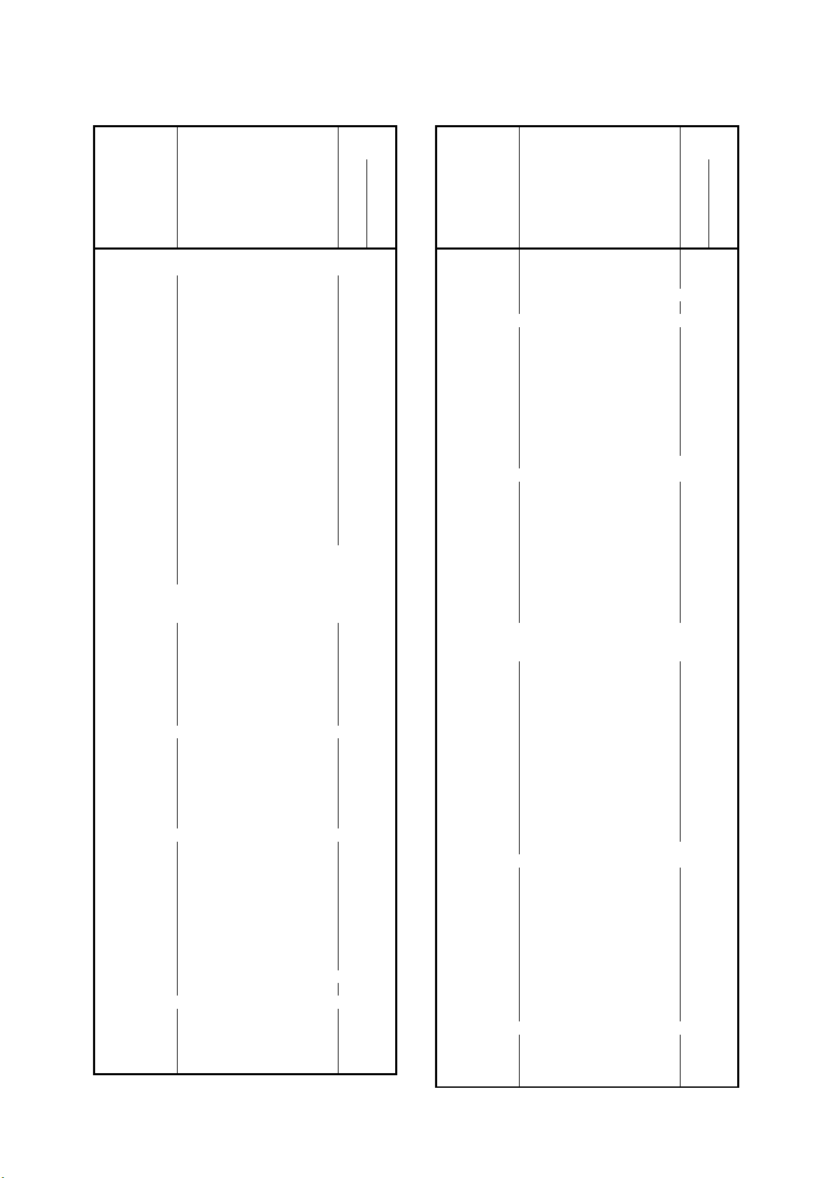
T R O G E S AIRSET – Montage-, Betriebs- und Wartungsanleitung
X
X
X
X
X
X
X
X
X
X
X
X
X
X
AIRSET – Assembly, Operation and Maintenance Instructions
Tätigkeiten
Ausfüh-
rung
Tätigkeiten
Ausfüh-
rung
An Baugruppen und
Elementen
Baugruppen-Nr
Bauelemente-Nr
Tätigkeiten-Nr
1 Luftfördereinrichtung
1 1 Ventilatoren
1 1 1 Auf Verschmutzung,
Beschädigung, Korrosion und
Befestigung prüfen M
1 1 2 Funktionserhaltendes reinigen
1 1 3 Laufrad auf Unwucht prüfen M
1 1 4 Schaufelverstelleinrichtung
auf Funktion prüfen J
1 1 5 Lager auf Geräusch prüfen M
1 1 6 Nachschmierbare Lager
schmieren H
1 1 7 Flexible Verbindung auf
Dichtheit prüfen V
1 1 8 Schwingungsdämpfer auf
Funktion prüfen H
1 1 9 Schutzeinrichtung auf
Funktion prüfen M
1 1 10 Drallregler auf Funktion
prüfen J
1 1 11 Entwässerung auf Funktion
prüfen H
1 1 12 Hygienischen Zustand prüfen M
1 1 13 Antriebselemente siehe Pos 10
1 1 14 MSR -Einrichtungen siehe VDMA 24186
Teil 4
2 Wärmeübertrager
2 1 Lufterwärmer (Luft/Flüssigkeit)
2 1 1 Auf luftseitige Verschmutzung
Beschädigung u. Korrosion
prüfen V
2 1 2 Funktionserhaltendes reinigen
2 1 3 Vor- u. Rücklauf auf Funktion
prüfen H
2 1 4 Entlüften J
2 1 5 Hygienischen Zustand prüfen M
2 2 Elektro-Lufterwärmer
2 2 1 Auf Zunderansatz und
Korrosion prüfen M
2 2 2 Funktionserhaltendes reinigen
2 2 3 Auf Funktion prüfen H
2 2 4 Steuer- und Sicherheitsein-
richtung auf Funktion prüfen M
2 2 5 Hygienischen Zustand prüfen M
2 3 Luftkühler (Luft/Flüssigkeit)
2 3 1 Auf luftseitige Verschmutz-
ung, Beschädigung u.
Korrosion prüfen V
2 3 2 Funktionserhaltendes reinigen
2 3 3 Vor- u. Rücklauf auf Funktion
prüfen H
2 3 4 Entlüften J
2 3 5 Wasserablauf und Geruchs-
verschluss auf Funktion
prüfen V
2 3 6 Tropfenabscheider siehe Pos. 4.2
2 3 7 Hygienischen Zustand prüfen M
2 4 Verdampfer (Luft/Kältemittel)
2 4 1 Auf luftseitige Verschmutz-
ung, Beschädigung, Korrosion
und Vereisung prüfen V
2 4 2 Funktionserhaltendes reinigen
2 4 3 Auf Vereisung prüfen V
periodisch
An Baugruppen und
Elementen
bei Bedarf
Baugruppen-Nr
Bauelemente-Nr
Tätigkeiten-Nr
2 4 4 Wasserablauf und
Geruchsverschluss auf
Funktion prüfen
2 4 5 Tropfenabscheider siehe Pos. 4.2
2 4 6 Hygienischen Zustand prüfen M
2 5 Rotations- Wärmeübertrager
2 5 1 Auf luftseitige Verschmutz-
ung u. Korrosion prüfen M
2 5 2 Funktionserhaltendes reinigen
2 5 3 Rotor auf Unwucht prüfen J
2 5 4 Lager auf Geräusch prüfen M
2 5 5 Lager mit Nachschmier-
einrichtung fetten J
2 5 6 Dichtelement auf Funktion
prüfen (Sichtprüfung) J
2 5 7 Hygienischen Zustand prüfen M
2 5 8 Antriebselemente siehe Pos 10
2 6 Kreuzstrom-Wärmetauscher
2 6 1 Auf luftseitige
Verschmutzung,
Beschädigung u. Korrosion
prüfen V
2 6 2 Funktionserhaltendes reinigen
2 6 3 Reinigungseinrichtung auf
Funktion prüfen H
2 6 4 Wasserablauf und Geruchs-
verschluss auf Funktion
prüfen V
2 6 5 Hygienischen Zustand prüfen M
3 Luftfilter
3 1 Rollbandfilter
3 1 1 Auf Verschmutzung,
Beschädigung und Korrosion
prüfen M
3 1 2 Funktionserhaltendes reinigen
3 1 3 Differenzdruck messen M
3 1 4 Filtervorschub auf Funktion
prüfen V
3 1 5 Steuereinheit auf Funktion
prüfen V
3 1 6 Messflüssigkeit nachfüllen
3 1 7 Filtermedium auf Vorrat
prüfen M
3 1 8 Filterband auswechseln
3 1 9 Hygienischen Zustand prüfen M
3 1 10 Antriebselemente siehe Pos 10
3 2 Trockenschichtfilter
3 2 1 Auf Verschmutzung,
Beschädigung und Korrosion
prüfen M
3 2 2 Funktionserhaltendes reinigen
3 2 3 Differenzdruck messen M
3 2 4 Filterauflage auf Dichtheit
prüfen H
3 2 5 Filtermedium (regenerierbar)
reinigen
3 2 6 Filtermedium auswechseln
und dokumentieren
3 2 7 Hygienischen Zustand prüfen M
3 3 Elektrofilter
3 3 1 Auf Verschmutzung,
Beschädigung und Korrosion
prüfen M
3 3 2 Funktionserhaltendes reinigen
periodisch
bei Bedarf
32
Page 33
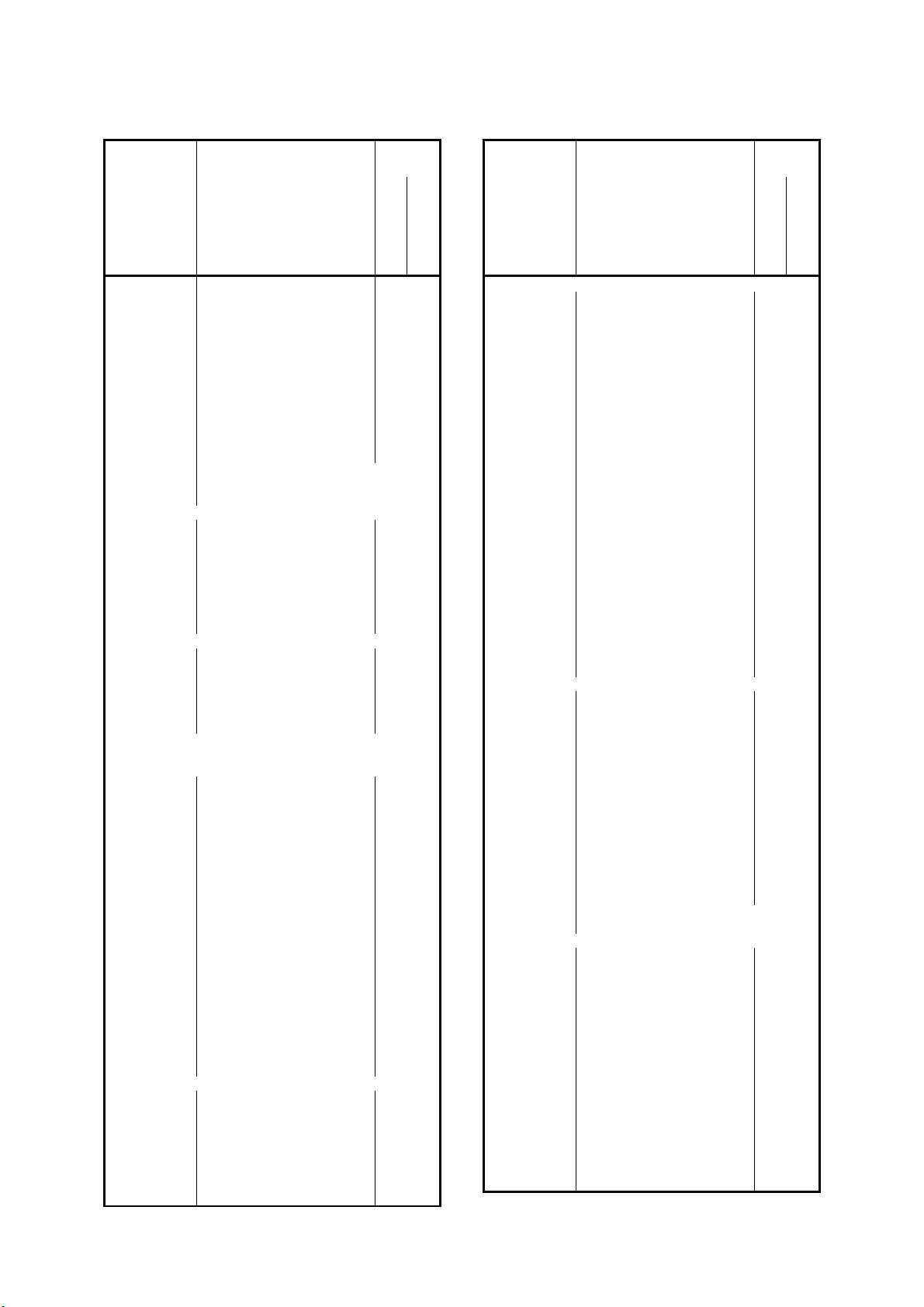
T R O G E S AIRSET – Montage-, Betriebs- und Wartungsanleitung
X
X
X
X
X
X
X
X
X
X
X
X
AIRSET – Assembly, Operation and Maintenance Instructions
Tätigkeiten
Ausfüh-
rung
Tätigkeiten
Ausführung
An Baugruppen und
Elementen
Baugruppen-Nr
Bauelemente-Nr
Tätigkeiten-Nr
3 3 3 Ionisationsdrähte auf
Beschädigung prüfen H
3 3 4 Ionisationsdrähte
auswechseln
3 3 5 Filterzellen auf Beschädigung
und Funkenschlag prüfen M
3 3 6 Isolatoren auf festen Sitz
prüfen (Sichtprüfung) V
3 3 7 Isolatoren auswechseln
3 3 8 Stromaufnahme messen H
3 3 9 Reinigungseinrichtung auf
Funktion prüfen H
3 3 10 Hygienischen Zustand prüfen M
3 3 11 Antriebselemente siehe Pos 10
3 3 12 MSR- Einrichtungen siehe VDMA 24186
Teil 4
3 4 Sorptionsfilter
3 4 1 Auf äußere Verschmutzung,
Beschädigung u. Korrosion
prüfen H
3 4 2 Funktionserhaltendes reinigen
3 4 3 Filtereinsatz auf dichten Sitz
prüfen H
3 4 4 Filtereinsatz auswechseln
3 4 5 Hygienischen Zustand prüfen M
3 5 Schwebstofffilter
(Die Wartungstätigkeiten
können nicht pauschal fest-
gelegt werden. Sie ergeben
sich aus den jeweils vorlieg-
enden Einbau- und Betriebs-
bedingungen)
4 Luftbefeuchter
4 1 Umlaufsprüh- u. Verdunstungsbefeuchter
4 1 1 Auf Verschmutzung,
Inkrustation, Beschädigung
und Korrosion prüfen V
4 1 2 Funktionserhaltendes reinigen
4 1 3 Wassereinspeisung und -
verteilung auf Funktion prüfen M
4 1 4 Wasserstand prüfen M
4 1 5 Reguliereinrichtung für
Wasserstand nachstellen
4 1 6 Absalzvorrichtung auf
Funktion prüfen V
4 1 7 Absalzvorrichtung einstellen
4 1 8 Ab- u. Überlauf auf Funktion
prüfen M
4 1 9 Schmutzfänger auf
Verschmutzung prüfen M
4 1 10 Schmutzfänger reinigen
4 1 11 Pumpe auf Funktion prüfen M
4 1 12 Keimzahlmessung (KBE/ml)
durchführen H
4 1 13 Hygienischen Zustand prüfen M
4 2 Tropfenabscheider/Gleichrichter
4 2 1 Auf Verschmutzung,
Inkrustation, Beschädigung
und Korrosion prüfen V
4 2 2 Funktionserhaltendes reinigen
4 2 3 Wasserablauf und Geruchs-
verschluss auf Funktion
prüfen V
4 2 4 Hygienischen Zustand prüfen M
periodisch
X
X
X
X
An Baugruppen und
Elementen
bei Bedarf
Baugruppen-Nr
Bauelemente-Nr
Tätigkeiten-Nr
4 3 Dampfbefeuchter mit eigenem Dampferzeuger
4 3 1 Auf Verschmutzung,
Beschädigung und Korrosion
prüfen V
4 3 2 Funktionserhaltendes reinigen
4 3 3 Wassereinspeisung auf
Funktion und Wasserstand
prüfen V
4 3 4 Schmutzfänger auf
Verschmutzung prüfen V
4 3 5 Schmutzfänger reinigen
4 3 6 Magnetventile auf Funktion
prüfen M
4 3 7 Steuer- und
Sicherheitseinrichtung auf
Funktion prüfen M
4 3 8 Dampfzylinder auf Ablagerung
prüfen M
4 3 9 Dampfzylinder
auswechseln/regenerieren
4 3 10 Dampfverteiler und Düsen auf
Funktion prüfen V
4 3 11 Dampfleitung und Kondensat-
leitung auf Dichtheit und
Beschädigung prüfen H
4 3 12 Auf Kondensatniederschlag
prüfen
4 3 13 Hygienischen Zustand prüfen M
4 4 Dampfbefeuchter ohne eigenen Dampferzeuger
4 4 1 Auf Verschmutzung,
Beschädigung und Korrosion
prüfen V
4 4 2 Funktionserhaltendes reinigen
4 4 3 Schmutzfänger auf
Verschmutzung prüfen V
4 4 4 Schmutzfänger reinigen
4 4 5 Regelventil auf Funktion
prüfen V
4 4 6 Dampfverteiler und
Kondensatleitung auf
Funktion prüfen H
4 4 7 Auf Kondensatniederschlag
prüfen
4 4 8 Hygienischen Zustand prüfen M
4 4 9 MSR- Einrichtungen siehe VDMA 24186
Teil 4
4 5 Ultraschall- Zerstäubungs- u. Hybridbefeuchter
4 5 1 Auf Verschmutzung,
Inkrustation, Beschädigung
und Korrosion prüfen V
4 5 2 Funktionserhaltendes reinigen
4 5 3 Wasserbehälter reinigen M
4 5 4 Elektrische Anlage auf
Funktion prüfen V
4 5 5 Energiewandler (nur bei
Ultraschallbefeuchter) auf
Funktion prüfen V
4 5 6 Energiewandler (nur bei Ultra-
schallbefeuchter) ersetzen
4 5 7 Wassereinspeisung u- -
verteilung auf Funktion prüfen M
4 5 8 Pumpe auf Funktion prüfen V
4 5 9 Hygienischen Zustand prüfen M
periodisch
bei Bedarf
- 33 -
Page 34
T R O G E S AIRSET – Montage-, Betriebs- und Wartungsanleitung
X
X
X
X
X
X
X
X
X
X
X
X
X
X
X
X
AIRSET – Assembly, Operation and Maintenance Instructions
Tätigkeiten
Ausfüh-
rung
An Baugruppen und
Elementen
Baugruppen-Nr
Bauelemente-Nr
Tätigkeiten-Nr
5 Bauelemente des Luftverteilsystems
5 1 Wetterschutzgitter und sonstige Gitter
5 1 1 Auf Verschmutzung,
Beschädigung, Korrosion und
Befestigung prüfen H
5 1 2 Funktionserhaltendes reinigen
5 2 Jalousieklappen
5 2 1 Auf Verschmutzung,
Beschädigung und Korrosion
prüfen H
5 2 2 Funktionserhaltendes reinigen
5 2 3 Auf mechanische Funktion
prüfen H
5 2 4 Lager und Gestänge
schmieren
5 2 5 Stellantriebe siehe VDMA 20186 Teil 4
5 3 Kammern
5 3 1 Auf Verschmutzung,
Beschädigung und Korrosion
prüfen J
5 3 2 Funktionserhaltendes reinigen
5 3 3 Abläufe auf Funktion prüfen J
5 3 4 Abläufe reinigen
5 3 5 Türen und Verschlüsse auf
Gängigkeit u. Dichtheit prüfen J
5 3 6 Wärmedämmung auf
Beschädigung prüfen J
5 3 7 Flexible Verbindungen auf
Dichtheit prüfen J
5 5 8 Kammern innen reinigen
5 5 9 Hygienischen Zustand prüfen M
5 4 Brandschutzklappen und -ventile
5 4 1 Einrastvorrichtung auf
Verschmutzung u. Funktion
prüfen J
5 4 2 Auslösevorrichtung auf
Verschmutzung u. Funktion
prüfen J
5 4 3 Dichtungen auf
Verschmutzung und
Beschädigung prüfen J
5 4 4 Funktionserhaltendes reinigen
5 4 5 Auslöseelement auswechseln
5 4 6 Auf Gängigkeit prüfen J
5 4 7 Stellungsanzeige auf Funktion
prüfen J
5 4 8 Stellantriebe siehe VDMA 20186 Teil 4
5 5 Luftkanäle
5 5 1 Zugängliche Kanalabschnitte
einschließlich vorhandener
Wärmedämmung und
Befestigung auf äußere
Beschädigung und Korrosion
prüfen (Sichtprüfung) J
5 5 2 Abläufe auf Funktion prüfen J
5 5 3 Abläufe reinigen
5 5 4 Zugängliche flexible
Verbindungen auf Dichtheit
prüfen (Sichtprüfung) J
5 5 5 Zugängliche Kanalabschnitte
stichprobenweise innen auf
Verschmutzung prüfen,
hygienischen Zustand prüfen M
periodisch
Tätigkeiten
Ausführung
An Baugruppen und
Elementen
bei Bedarf
Baugruppen-Nr
Bauelemente-Nr
Tätigkeiten-Nr
5 6 Luftdurchlässe
5 6 1 Textile Luftdurchlässe auf
äußere Beschädigung und
Verschmutzung prüfen
(Sichtprüfung) J
5 7 Schalldämpfer
5 7 1 Auf Verschmutzung,
Beschädigung und Korrosion
prüfen J
5 8 Misch-/Entspannungskästen und
Volumenstromregler
5 8 1 Auf Verschmutzung,
Beschädigung und Korrosion
prüfen J
5 8 2 Funktionserhaltendes reinigen
5 8 3 Regelklappen auf Funktion
prüfen J
5 8 4 Stellantriebe siehe VDMA 20186 Teil 4
5 9 Absperr- u. Abgleichelemente
5 9 1 Auf Verschmutzung,
Beschädigung und Korrosion
prüfen J
5 9 2 Funktionserhaltendes reinigen
5 9 3 Auf Funktion prüfen J
5 9 4 Stellantriebe siehe VDMA 20186 Teil 4
9 Schaltschränke, MSR -Einrichtungen und
Gebäudeautomatisationssysteme siehe
VDMA 22186 Teil 4
10 Antriebselemente
10 1 Elektromotoren
10 1 1 Auf Verschmutzung,
Befestigung, Beschädigung
und Korrosion prüfen M
10 1 2 Funktionserhaltendes reinigen
10 1 3 Drehrichtung prüfen M
10 1 4 Anschlussklemmen
nachziehen
10 1 5 Spannung messen V
10 1 6 Anschlussklemmen auf festen
Sitz prüfen H
10 1 7 Stromaufnahmen messen V
10 1 8 Phasensymmetrie messen V
10 1 9 Auf Laufruhe und Erwärmung
prüfen M
10 1 10 Lager auf Geräusch prüfen M
10 1 11 Lager mit
Nachschmiereinrichtung
fetten H
10 1 12 Schutzeinrichtung auf
Funktion prüfen M
10 2 Riementriebe
10 2 1 Auf Verschmutzung,
Beschädigung und Verschleiß
prüfen M
10 2 2 Funktionserhaltendes reinigen
10 2 2 Auf Spannung und Fluchtung
prüfen M
10 2 3 Nachstellen
10 2 4 Riemen auswechseln
10 2 5 Schutzeinrichtung auf
Funktion prüfen M
periodisch
bei Bedarf
- 34 -
Page 35
T R O G E S AIRSET – Montage-, Betriebs- und Wartungsanleitung
X
X
AIRSET – Assembly, Operation and Maintenance Instructions
Tätigkeiten
Ausfüh-
rung
Tätigkeiten
Ausführung
An Baugruppen und
Elementen
Baugruppen-Nr
Bauelemente-Nr
Tätigkeiten-Nr
10 3 Antriebskupplung
10 3 1 Auf Verschmutzung,
Beschädigung, Korrosion und
Befestigung prüfen M
10 3 2 Funktionserhaltendes reinigen X
10 2 3 Ausrichtung prüfen V
10 3 4 Temperatur prüfen V
10 3 5 Öl auswechseln
10 3 6 Schutzeinrichtung auf
Funktion prüfen M
10 4 Getriebe
10 4 1 Auf Verschmutzung,
Beschädigung und Korrosion
prüfen M
periodisch
An Baugruppen und
Elementen
bei Bedarf
Baugruppen-Nr
Bauelemente-Nr
Tätigkeiten-Nr
10 4 2 Auf Befestigung und
Geräusch Prüfen M
10 4 3 Funktionserhaltendes reinigen
10 4 4 Ausrichtung prüfen V
10 5 5 Öl auswechseln H
11 Dokumentation und Kennzeichnung
11 1 Wartungsintervalle Unterlagen (z.B. Schemata,
Herstellervorschriften)
11 1 1 Auf Vorhandensein prüfen M
11 2 Bestehende Anlagenkennzeichnung
(Beschilderung, Farbkennzeichnung,
Typenschild/Zulassungszeichen)
11 2 1 Auf Vorhandensein prüfen M
periodisch
bei Bedarf
- 35 -
Page 36

T R O G E S AIRSET – Montage-, Betriebs- und Wartungsanleitung
AIRSET – Assembly, Operation and Maintenance Instructions
Scope of services
Source:
VDMA 24186 part 0 and VDMA 24186 part 1.
Scope of application and intention:
This hand out apply for air handling units. AHU’s are units to discharge
and guarantee the room air conditions.
Scope of activities:
The activities according this hand out expects qualified personal.
Service interval:
Periods:
M monthly (ca. 730 operating hours)
Q quarterly (ca. 2190 operating hours)
H half-yearly (ca. 4380 operating hours)
Y yearly (ca. 8760 operating hours)
On demand:
The activities are conform to the results of the unit check at the
maintenance.
Overview
1 Air discharge device
1.1 Fans
2 Heat exchanger
2.1 Air heater (air/fluid)
2.2 Electric air heater
2.3 Air cooler (air/fluid)
2.4 Evaporator (air/refrigerant)
2.5 Rotary heat exchanger
2.6 Plate heat exchanger
3 Air filter
3.1 Roll band filter
3.2 Dry layer filter
3.3 Electric filter
3.4 Sorption filter
3.5 Filter for suspended matter
4 Humidifier
4.1 air washer and honeycomb
4.2 Drop eliminator / Flow straightener
4.3 Humidifier (medium steam) with
Steam generator
4.4 Humidifier (medium steam) without
steam generator
4.5 Ultrasonic, Spray and Hybrid
humidifier
5 Elements of the air distribution system
5.1 Weather louver
5.2 Damper
5.3 Camper
5.4 Fire damper and valve
5.5 Duct
5.6 Grille
5.7 Silencer
5.8 Mixing-/relaxation camper und air
flow regulator
5.9 Isolation- and adjustment element
9 Control box, ICA- devices and
building automatisation system
10 Drive units
10.1 Electric motor
10.2 Belt drive
10.3 Drive coupling
10.4 Gear
11 Documentation and labelling
11.1 Service interval documents
11.2 Existing unit marking
- 36 -
Page 37
T R O G E S AIRSET – Montage-, Betriebs- und Wartungsanleitung
X
X
X
X
X
X
X
X
X
X
X
X
X
X
X
X
X
X
AIRSET – Assembly, Operation and Maintenance Instructions
activities interval
components and
elements
Component-No
element-No
activity-No
1 Air discharge device
1 1 Fans
1 1 1 Check pollution, damaging,
corrosion and fastenings. M
1 1 2 Cleaning for save function
1 1 3 Check unbalancing of wheel M
1 1 4 Check function of the blade
adjust device Y
1 1 5 Check noise of bearings M
1 1 6 Grease all regreasable
bearings H
1 1 7 Check tightness of flexible
canvas Q
1 1 8 Check function of anti
vibration dampers H
1 1 9 Check function of safety
devices M
1 1 10 Check function of vane
control Y
1 1 11 Check function of drainage H
1 1 12 Check hygienic condition M
1 1 13 Drive units see pos 10
1 1 14 ICA -devices see VDMA 24186 part 4
2 Heat exchangers
2 1 Air heater (air/fluid)
2 1 1 Check airside pollution,
damaging and corrosion Q
2 1 2 Cleaning for save function
2 1 3 Check function of flow and
return H
2 1 4 Ventilate Y
2 1 5 Check hygienic condition M
2 2 Electric heater
2 2 1 Check scale formation and
corrosion M
2 2 2 Cleaning for save function
2 2 3 Check function H
2 2 4 Check ICA and safety devices M
2 2 5 Check hygienic condition M
2 3 Air cooler (air/fluid)
2 3 1 Check airside pollution,
damaging and corrosion Q
2 3 2 Cleaning for save function
2 3 3 Check function of flow and
return H
2 3 4 Ventilate Y
2 3 5 Check function of drain and
siphon Q
2 3 6 Drop eliminator see pos. 4.2
2 3 7 Check hygienic condition M
2 4 Evaporator (air/refrigerant)
2 4 1 Check airside pollution,
damaging, corrosion and icing Q
2 4 2 Cleaning for save function
2 4 3 Check icing Q
2 4 4 Check function of drain and
siphon
2 4 5 Drop eliminator see pos. 4.2
2 4 6 Check hygienic condition M
2 5 Rotary heat exchanger
2 5 1 Check airside pollution,
damaging and corrosion M
2 5 2 Cleaning for save function
2 5 3 Check unbalancing of wheel Y
2 5 4 Check noise of bearings M
period
activities interval
components and
elements
on demand
Component-No
element-No
activity-No
2 5 5 Grease all regreasable
bearings Y
2 5 6 Check function of sealing
elements (sight check) Y
2 5 7 Check hygienic condition M
2 5 8 Drive units see pos 10
2 6 Plate heat exchanger
2 6 1 Check airside pollution,
damaging and corrosion Q
2 6 2 Cleaning for save function
2 6 3 Check function of cleaning
device H
2 6 4 Check function of drain and
siphon Q
2 6 5 Check hygienic condition M
3 Air filter
3 1 Roll band filter
3 1 1 Check pollution, damaging
and corrosion M
3 1 2 Cleaning for save function
3 1 3 Detect pressure drop M
3 1 4 Check function of filter feed
rate Q
3 1 5 Check function of ICA device Q
3 1 6 Refill measuring solution
3 1 7 Check reserve of filter
medium M
3 1 8 Change filter band
3 1 9 Check hygienic condition M
3 1 10 Drive units see pos 10
3 2 Dry layer filter
3 2 1 Check pollution, damaging
and corrosion M
3 2 2 Cleaning for save function
3 2 3 Detect pressure drop M
3 2 4 Check tightness of filter frame H
3 2 5 Clean filter medium if
regenerative
3 2 6 Change filter medium and
keep records
3 2 7 Check hygienic condition M
3 3 Electric filter
3 3 1 Check pollution, damaging
and corrosion M
3 3 2 Cleaning for save function
3 3 3 Check damaging of
ionisations wires H
3 3 4 Change ionisation wires
3 3 5 Check filter cells against
damaging and sparking M
3 3 6 Check tight seat of insulators Q
3 3 7 Change insulators
3 3 8 Detect current consumption H
3 3 9 Check function of cleaning
device H
3 3 10 Check hygienic condition M
3 3 11 Drive units see pos 10
3 3 12 ICA -devices see VDMA 24186 part 4
3 4 Sorption filter
3 4 1 Check physical pollution,
damaging and corrosion H
3 4 2 Cleaning for save function
3 4 3 Check tight seat of filter insert H
3 4 4 Change filter insert
3 4 5 Check hygienic condition M
period
on demand
- 37 -
Page 38
T R O G E S AIRSET – Montage-, Betriebs- und Wartungsanleitung
X
X
X
X
X
X
X
X
X
X
X
X
X
X
X
X
AIRSET – Assembly, Operation and Maintenance Instructions
activities interval
components and
elements
Component-No
element-No
activity-No
3 5 Filter for suspended matter
(Global activities can not be
appointed. They are
depending on the particular
conditions of installation and
operation)
4 Humidifier
4 1 Air washer and honeycomb
4 1 1 Check pollution, incrustation,
damaging and corrosion Q
4 1 2 Cleaning for save function
4 1 3 Check function of water
supply and distribution M
4 1 4 Check water level M
4 1 5 Adjust regulation device for
water level
4 1 6 Check function of sludge
device Q
4 1 7 Adjust sludge device
4 1 8 Check function of drain and
overflow M
4 1 9 Check pollution of strainer M
4 1 10 Clean strainer
4 1 11 Check function of pump M
4 1 12 Detect bacterial count H
4 1 13 Check hygienic condition M
4 2 Drop eliminator / Flow straightener
4 2 1 Check pollution, incrustation,
damaging and corrosion Q
4 2 2 Cleaning for save function
4 2 3 Check function of drain and
siphon Q
4 2 4 Check hygienic condition M
4 3 Steam humidifier with steam generator
4 3 1 Check pollution, damaging
and corrosion Q
4 3 2 Cleaning for save function
4 3 3 Check function of water
supply and water level Q
4 3 4 Check pollution of strainer Q
4 3 5 Clean strainer
4 3 6 Check function of magnet
valve M
4 3 7 Check function of ICA and
safety device M
4 3 8 Check steam cylinder for
scaling M
4 3 9 Change or regenerate steam
cylinder
4 3 10 Check function of steam
distributor and nozzles Q
4 3 11 Check damage and tightness
of steam and condensate
hose H
4 3 12 Check for condensate
formation
4 3 13 Check hygienic condition M
4 4 Steam humidifier without steam generator
4 4 1 Check pollution, damaging
and corrosion Q
4 4 2 Cleaning for save function
4 4 3 Check pollution of strainer Q
4 4 4 Clean strainer
period
activities interval
components and
elements
on demand
X
X
X
X
Component-No
element-No
activity-No
4 4 5 Check function of regulation
valve Q
4 4 6 Check function of steam
distributor and condensate
line H
4 4 7 Check for condensate
formation
4 4 8 Check hygienic condition M
4 4 9 ICA -devices see VDMA 24186 part 4
4 5 Ultrasonic- Spray- and. Hybrid humidifier
4 5 1 Check pollution, incrustation,
damaging and corrosion Q
4 5 2 Cleaning for save function
4 5 3 Clean water tank M
4 5 4 Check function of electrical
system Q
4 5 5 Check function of energy
converter (only for ultrasonic
humidifier) Q
4 5 6 Change energy converter
(only for ultrasonic humidifier)
4 5 7 Check function of water
supply and distribution M
4 5 8 Check function of pump Q
4 5 9 Check hygienic condition M
5 Elements of the air distribution system
5 1 Weather lovers
5 1 1 Check pollution, damaging
and corrosion H
5 1 2 Cleaning for save function
5 2 Dampers
5 2 1 Check pollution, damaging
and corrosion H
5 2 2 Cleaning for save function
5 2 3 Check mechanical function H
5 2 4 Grease bearings and
connecting rods
5 2 5 Damper actuator see VDMA 20186 part 4
5 3 Chambers
5 3 1 Check pollution, damaging
and corrosion Y
5 3 2 Cleaning for save function
5 3 3 Check function of drain Y
5 3 4 Clean drain
5 3 5 Check tightness and free
movement of doors and
hinges Y
5 3 6 Check thermal insulation for
damaging Y
5 3 7 Check tightness of flexible
canvas Y
5 5 8 Clean chambers inside
5 5 9 Check hygienic condition M
5 4 Fire dampers and valves
5 4 1 Check catching device for
function and damaging Y
5 4 2 Check tripping device for
function and pollution Y
5 4 3 Check sealing for damaging
and pollution Y
5 4 4 Cleaning for save function
5 4 5 Change tripping element
5 4 6 Check free movement Y
5 4 7 Check function of position
indicator Y
period
on demand
- 38 -
Page 39
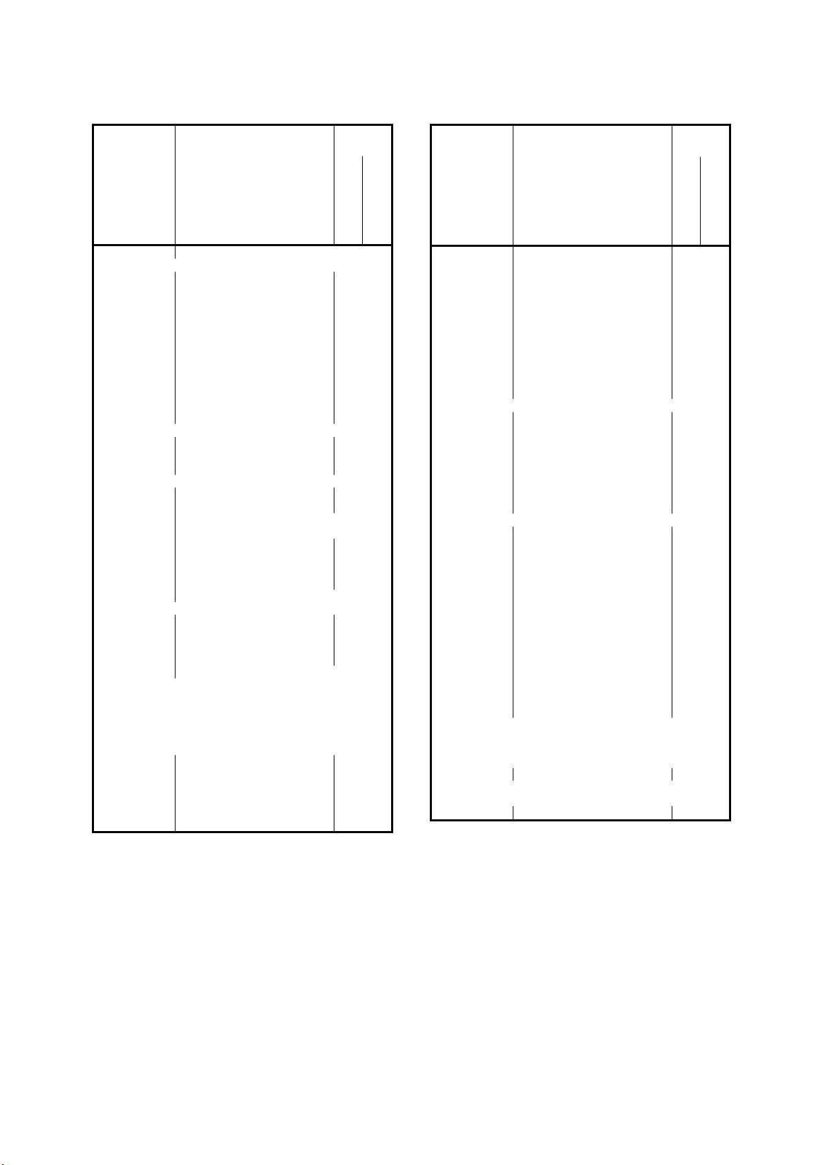
T R O G E S AIRSET – Montage-, Betriebs- und Wartungsanleitung
X
X
X
X
X
X
X
X
X
X
AIRSET – Assembly, Operation and Maintenance Instructions
activities interval
components and
elements
Component-No
element-No
activity-No
5 4 8 Damper actuator see VDMA 20186 part 4
5 5 Ducts
5 5 1 Check all accessible ducts
including the thermal
insulation for physical
damaging and corrosion (sight
check) Y
5 5 2 Check function of drain Y
5 5 3 Clean drain
5 5 4 Check tightness of accessible
flexible canvas (sight check) Y
5 5 5 Random check of accessible
ducts for internal pollution and
check hygienic condition M
5 6 Grille
5 6 1 Check textile grille for physical
damaging and pollution (sight
check) Y
5 7 Silencer
5 7 1 Check pollution, damaging
and corrosion Y
5 8 Mixing-/Relaxation camper and air flow
regulator
5 8 1 Check pollution, damaging
and corrosion Y
5 8 2 Cleaning for save function
5 8 3 Check function of damper Y
5 8 4 Damper actuator see VDMA 20186 part 4
5 9 Isolation- and adjustment element
5 9 1 Check pollution, damaging
and corrosion Y
5 9 2 Cleaning for save function
5 9 3 Check function Y
5 9 4 Damper actuator see VDMA 20186 part 4
9 Control box, ICA- devices and building
automatisation system see VDMA 22186 part 4
10 Drive units
10 1 Electric motor
10 1 1 Check pollution, tight seat,
damaging and corrosion M
10 1 2 Cleaning for save function
10 1 3 Check rotation direction M
10 1 4 Fasten connection terminal
10 1 5 Detect voltage Q
period
activities interval
components and
elements
on demand
Component-No
element-No
activity-No
10 1 6 Check tight seat of connection
terminal H
10 1 7 Detect current consumption Q
10 1 8 Check rotation direction of
three phase current. Q
10 1 9 Check smooth running and
temperature M
10 1 10 Check noise of bearings M
10 1 11 Grease all regreasable
bearings H
10 1 12 Check function of safety
devices M
10 2 Belt drive
10 2 1 Check pollution, damaging
and abrasion M
10 2 2 Cleaning for save function
10 2 2 Check tension and alignment M
10 2 3 Adjust belt drive
10 2 4 Change V-belt
10 2 5 Check function of safety
devices M
10 3 Drive coupling
10 3 1 Check pollution, tight seat,
damaging and corrosion M
10 3 2 Cleaning for save function X
10 2 3 Check alignment Q
10 3 4 Check temperature Q
10 3 5 Change oil
10 3 6 Check function of safety
devices M
10 4 Gear
10 4 1 Check pollution, damaging
and corrosion M
10 4 2 Check tight seat and noice M
10 4 3 Cleaning for save function
10 4 4 Check alignment Q
10 5 5 Change oil H
11 Documentation and Labelling
11 1 Service interval documents (e.g. plan,
manufacturer rules)
11 1 1 Check existence M
11 2 Existing unit marking (signs, color code, rating
plate, approval ID)
11 2 1 Check existence M
period
period
- 39 -
Page 40
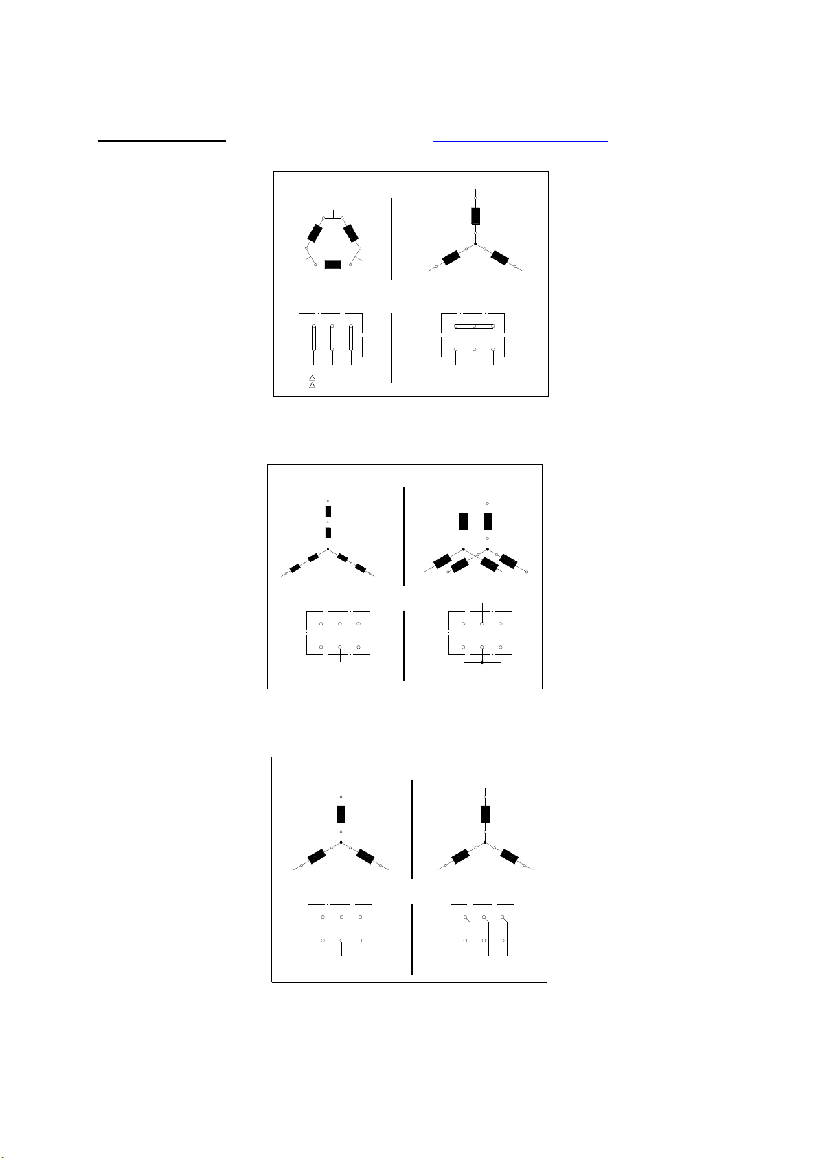
T R O G E S AIRSET – Montage-, Betriebs- und Wartungsanleitung
Schaltung für 1 Drehzahl
Schaltung für 2 Drehzahlen
1 speed winding
Winding with 2 speeds
Schaltung für 2 Drehzahlen
Winding with 2 speeds
AIRSET – Assembly, Operation and Maintenance Instructions
Anschlussbilder
zB.: 3000 1/min oder 1500 1/min
Motore bis 2,2 kW und
Nennspannung 230/400V
werden normalerweise direkt in
Sternschaltung betrieben
Motore ab 3,0 kW und
Nennspannung 690V werden in
Stern-Dreieck-Schaltung
angefahren.
im Verhältnis 1:2 mit
Dahlanderschaltung
Ausführung z.B. 3000/1500
1/min 2/4-polig
bzw. 1500/750 1/min 4/8-polig
mit getrennter Wicklung
Ausführung z.B. 1500/1000
1/min 4/6-polig
Bei Sonderausführungen auch
3000/1500 1/min 2/4-polig und
1500/750 1/min 4/8-polig
Schaltung der Wicklungsstränge
Circuit of the winding phases
L1
W2
U1
W1
L3 L2 V1
V2 V1
Schaltung am Klemmbrett
Circuit on the therminal bord
U1
- Schaltung
- circuit
Schaltung der Wicklungsstränge
Circuit of the winding phases
2U
1W
L3
Schaltung am Klemmbrett
Circuit on the therminal bord
2U 2V
1U 1V
L1
niedriege Drehzahl
Schaltung der Wicklungsstränge
Circuit of the winding phases
1W1
L3
Schaltung am Klemmbrett
Circuit on the therminal bord
2U1
1U1
L1
niedriege Drehzahl
U2W2 V2
V1 W1
L2L1 L3
L1
1U
2W
L2
low speed
1U1
1V1
low speed
U2
2V
1V
L2
2W
1W
L3
L1
1V1
L2 L3
2W12V1
1W1
L3L2
Connection Diagrams
L1
U1
U2
V2
W2
W1
L3
W2 V2U2
V1L1U1
W1
Y - Schaltung
Y - circuit
1U
2W
L3
L1 L2
2V2U 2W
hohe Drehzahl
high speed
L1
2U1
2W1
2U1 2V1 2W1
hohe Drehzahl
high speed
L2
L3L2
L1
2U
1W
1V
2V
L2
L3
1W1V1U
2V1
1W11U1 1V1
L3L2L1
e.g. 3000 1/min or 1500 1/min
Motors up to 2,2 kW and nominal
voltage 230/400V are usually
operate in star connection
Motors from 3,0 kW and nominal
voltage 690V start in star-delta
connection.
1:2 with tapped winding
Execution e.g. 3000/1500
1/min 2/4-pole
respectively 1500/750 1/min
4/8-pole
with brocken circuit
Execution e.g. 1500/1000
1/min 4/6-pole
For spezial design motors with
L2
3000/1500 1/min 2/4-pole and
1500/750 1/min 4/8-pole too
- 40 -
Page 41
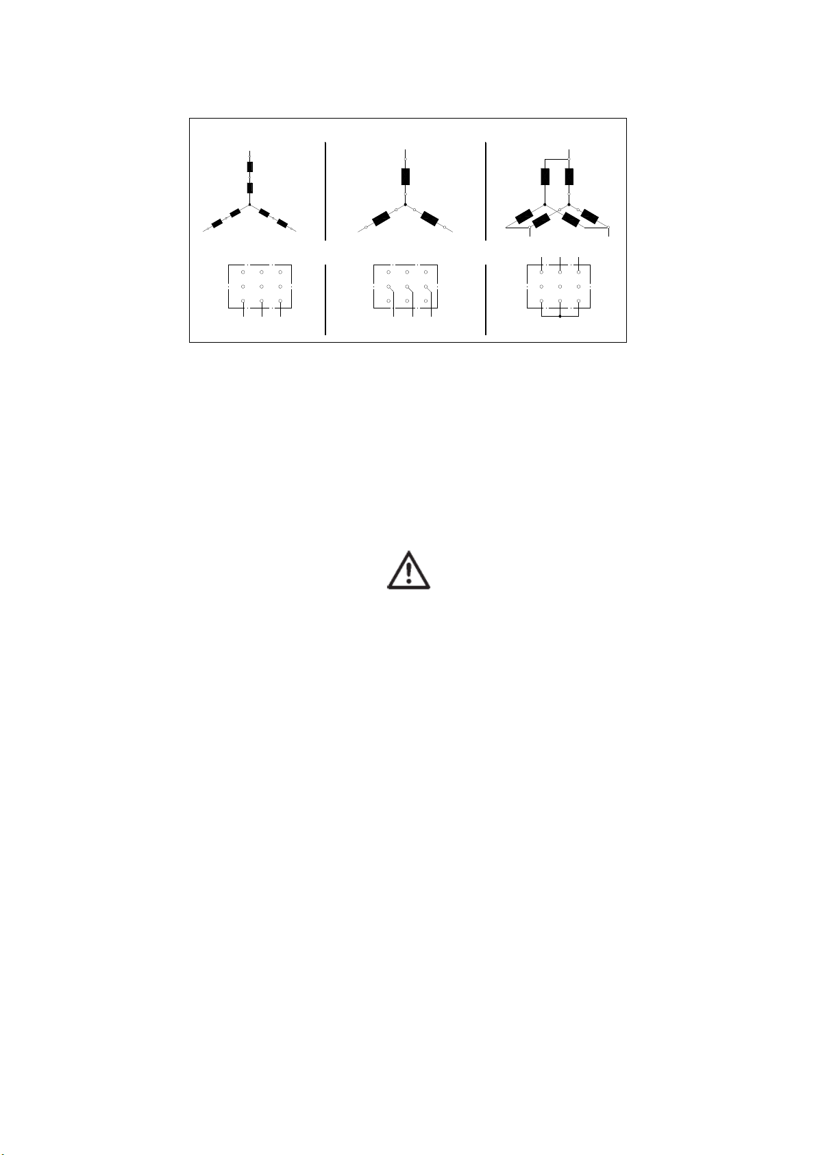
T R O G E S AIRSET – Montage-, Betriebs- und Wartungsanleitung
Schaltung für 3 Drehzahlen
Winding for 3 peeds
AIRSET – Assembly, Operation and Maintenance Instructions
Schaltung der Wicklungsstränge
Circuit of the winding phases
L1
1U
3W
3U
1W
L3
Schaltung am Klemmbrett
Circuit on the therminal bord
niedriege Drehzahl mittlere Drehzahl
3V
1V
L2
3U 3V 3W
2V2U 2W
1V1U 1W
L1 L2 L3
low speed medium speed
2W
L3
mit 2 getrennte Wicklungen,
1 davon in Dahlanderschaltung
Ausführung z.B.
1500/1000/750 1/min 4/6/8-polig
Die in der Montage- Betriebs- und
Wartungsanleitung angegeben
Motoranschlussbilder sind ausschließlich
Anschlussbeispiele und für den
Motoranschluss nicht allgemein gültig. Es
ist unbedingt die am Typenschild des
Motors angegebene Schaltungsart, bzw.
das im Klemmkasten des Motors
beigelegte Anschlussbild für den
Motoranschluss heranzuziehen. Bei nicht
Einhalten kann es zu Schäden an der
Motorwicklung kommen.
Die Art des Motoranlaufs (Direktanlauf bzw.
Ster-Dreieck-Anlauf) ist von der
Stromversorgungsanlage vor Ort und den
Bestimmungen des örtlichen EVU’s abhängig.
L1
2U
3U2U3V 3W
L11UL2 L3
L1
3U
1W
1V
1U
2V
L2
2W2V
1W1V
3W
L3 L2
3V
3U
3W
2V
2U
2W
1V1U
1W
hohe Drehzahl
high speed
3V
L3L2L1
with 2 broken circuits,
1 circuit in tapped winding
Execution e.g.
1500/1000/750 1/min 4/6/8-pole
All connection diagrams in this
assembly, operation and maintenance
instructions are just examples and not
general significant. Before connecting
motor look on the rating plate or the
connection diagram in the terminal
box. Failure to observe the instructions
may damage the motor windings.
The kind of motor start (if direct start or stardelta start) is depending on the rules of the
local power supply company (EPSC).
- 41 -
Page 42
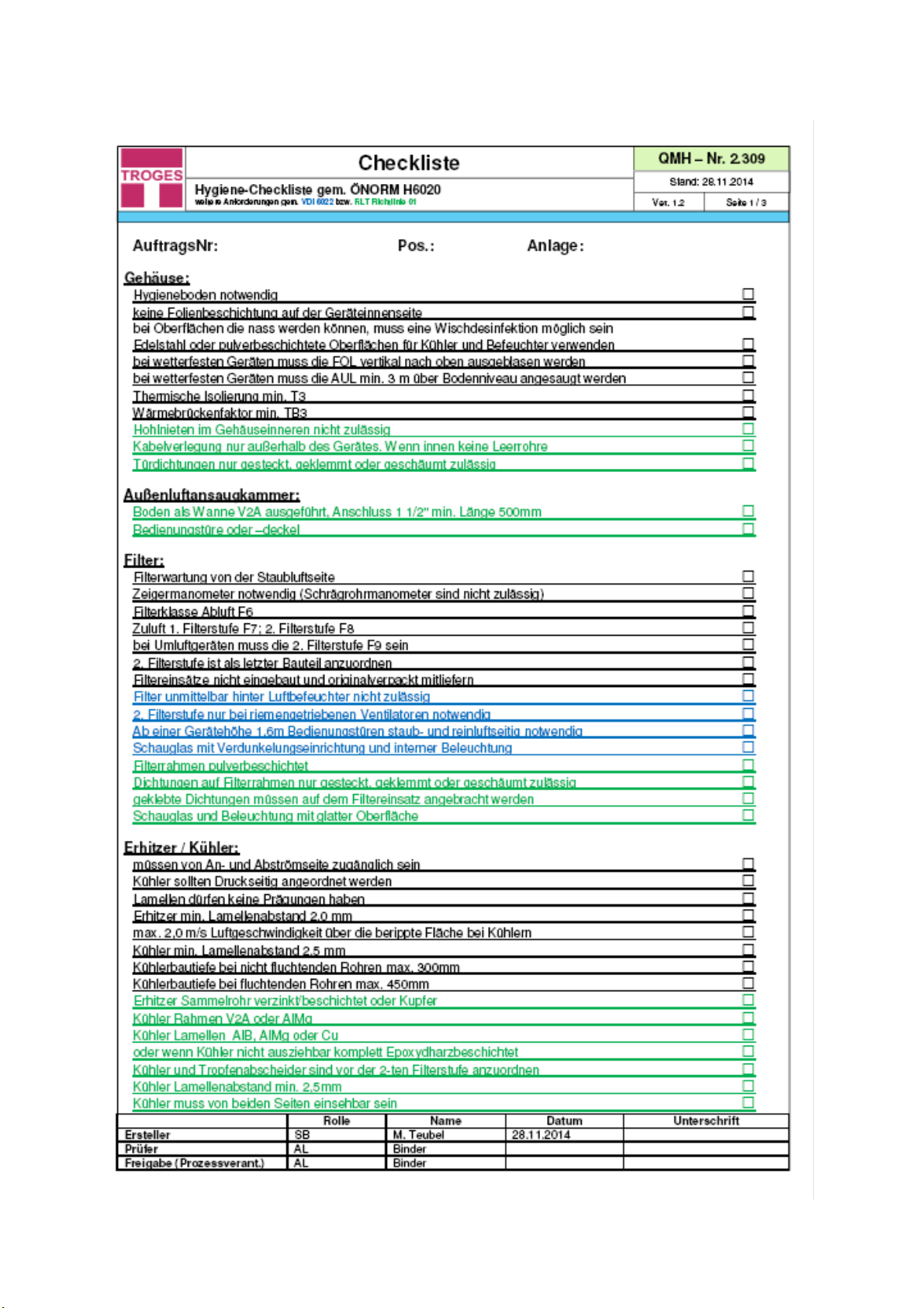
T R O G E S AIRSET – Montage-, Betriebs- und Wartungsanleitung
AIRSET – Assembly, Operation and Maintenance Instructions
- 42 -
Page 43
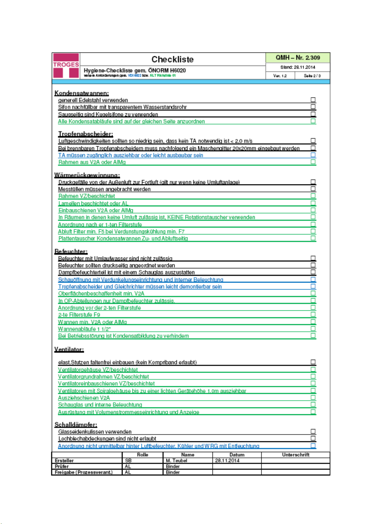
T R O G E S AIRSET – Montage-, Betriebs- und Wartungsanleitung
AIRSET – Assembly, Operation and Maintenance Instructions
- 43 -
Page 44
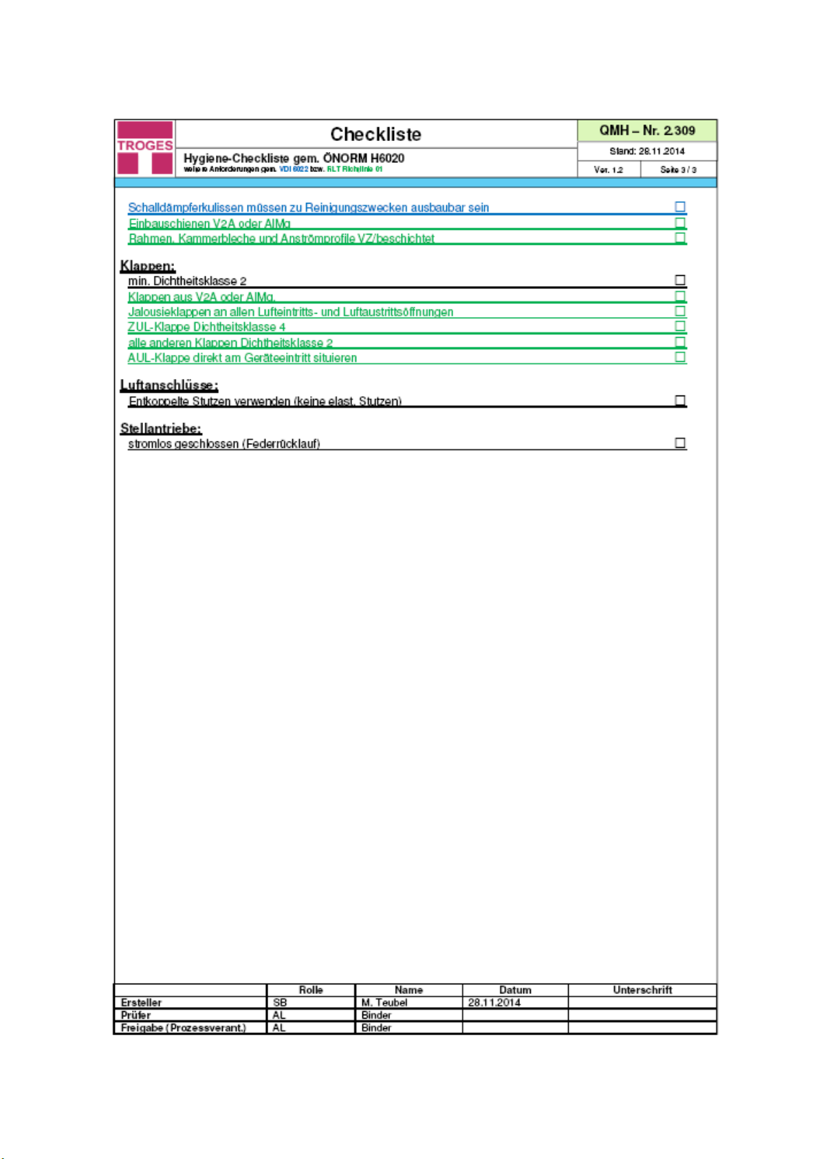
T R O G E S AIRSET – Montage-, Betriebs- und Wartungsanleitung
AIRSET – Assembly, Operation and Maintenance Instructions
- 44 -
Page 45
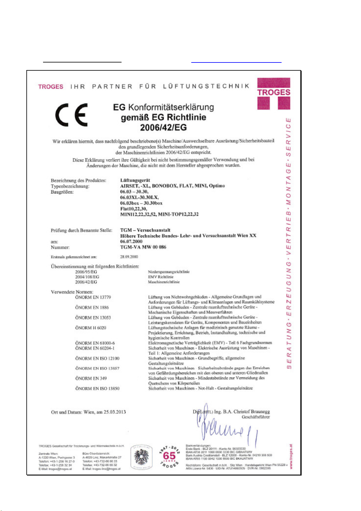
T R O G E S AIRSET – Montage-, Betriebs- und Wartungsanleitung
AIRSET – Assembly, Operation and Maintenance Instructions
Konformitätserklärung
Declaration of Conformity
- 45 -
Page 46

T R O G E S AIRSET – Montage-, Betriebs- und Wartungsanleitung
AIRSET – Assembly, Operation and Maintenance Instructions
46
Page 47

T R O G E S AIRSET – Montage-, Betriebs- und Wartungsanleitung
AIRSET – Assembly, Operation and Maintenance Instructions
47
Page 48
T R O G E S AIRSET – Montage-, Betriebs- und Wartungsanleitung
AIRSET – Assembly, Operation and Maintenance Instructions
D
IE
TROGES P
AIRSET Lüftungsgeräte (Standard, Hygiene, wetterfest)
BONOBOX Lüftungsgeräte (Standard, Hygiene, wetterfest)
HYGIENE PLUS Selbstdesinfizierende Lüftungsgeräte
EFG Schwimmhallen-Entfeuchtungsgeräte
TK Kompaktlüftungsgeräte
TWL Wohnraumlüftungsgeräte
AIRCUT Torluftschleier
Brandgas- bzw. Axialventilatoren
Brandschutzklappen
Lamellenbrandschutzklappen
Dach- bzw., Rohrventilatoren
Volumenstromregler
Regel-, Jalousie-, Absperrklappen
Sicherheitsdruckklappen
Elektro-Heizregister für Rohreinbau
UVC-Luftbehandlungsanlagen
Abluftbehandlungsanlagen
Kompaktluftreiniger
Lüftungsleitungen TROGES Flanschprofil
Flachkanäle
Spiralgefalzte Rohre
Formstücke und Sonderformstücke
Flexible Aluminiumschläuche
Längsfalzrohre und Formstücke für Späneabsaugung
Wetterschutzgitter eckig und rund
Vogel- und Insektenschutzgitter
Kanalschalldämpfer und Kulisseneinbausätze
Telefonie- und Rohrschalldämpfer
Z-Schalldämpfer
Schallschutzkapseln
Gewerbe- Küchenlüftungsdecken
Gewerbeküchenhauben
Zuluftschirme für Gewerbeküchen
Lüftungsventile; Lüftungsgitter und Auslässe
Industrielle Absaughauben
Luftbrunnen
Montagematerial, Stellantriebe
RODUKTPALETTE
TROGES P
AIRSET und BONOBOX Air Handling Units (AHU)
standard, hygienic, weatherproof
Self-disinfecting AHUs HYGIENE PLUS
EFG dehumidification units
TK Compact Air Handling Units
TWL AHUs for residential ventilation
AIRCUT Aircurtains
Smoke exhaust and axial fans
Fire dampers
Multi blade fire dampers
Roof and pipe fans
Air volume control dampers
Dampers and louvers
Safety pressure dampers
Electro heaters for duct installation
UVC air treatment systems
Exhaust air treatment systems
Air treatment generator
Rectangular Ducts and form pieces
Flat ducts
Spiro pipes and form pieces
Special form pieces
Flexanorm flexible Ducts
Pipes and form pieces for swarf extraction
Weathers Grilles
Bird and insect protection screens
Duct silencers and duct silencer kits
Telephony and pipe silencers
Z-silencers
Sound insulation capsules
Industrial Kitchen Ventilation Ceilings
Industrial kitchen hoods
Supply air screens for commercial kitchens
Ventilation grilles; Ventilation valves
Industrial extraction hoods
Air wells
Installation material and Actuators
RODUCT RANGE
Die TROGES Dienstleistungen:
Montage, Service, Wartung, Express Produktion, Küchendeckenreinigung, Lüftungskanalreinigung, Abholmarkt,
Naturmaßnahme, Dichtheitstest für Lüftungssysteme, Beratung, Angebote, Planungen
Kostenlose Software für Auslegung von Lüftungsgeräten, Axial- / Brandgasventilatoren, Schalldämpfer,
Stücklistenprogramm für Lüftungskomponenten
TECHNISCHE ÄNDERUNGEN VORBEHALTEN! Stand 09/ 2015
48
 Loading...