


SEARAILS RR-XXX
0-4-0 STEAM LOCOMOTIVES
ASSEMBLY MANUAL
T R Knapp Model Engineering
30 March 2015
ASSEMBLY MANUAL – SEARAILS RR-XX – 0-4-0 SYTEAM LOCOMOTIVES
1
This diagram shows basic
assembly of Nn3/Z Porter 0-4-0T
2
This diagram shows basic
assembly of Baldwin
“Dockside” 0-4-0T
3/30/15 T R Knapp Model Engineering 1
ASSEMBLY MANUAL – SEARAILS RR-XX – 0-4-0 SYTEAM LOCOMOTIVES
3
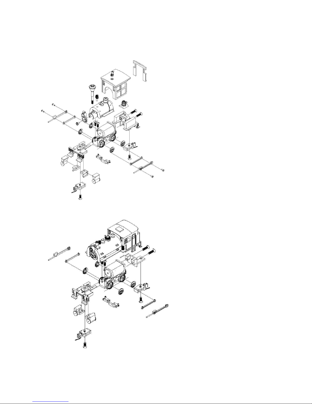
Pull drivers from ends of axles
with axles still in PowerMAX!
chassis.
4
Apply drop of CA to wiper
insulating bushing to fix in place
3/30/15 T R Knapp Model Engineering 2
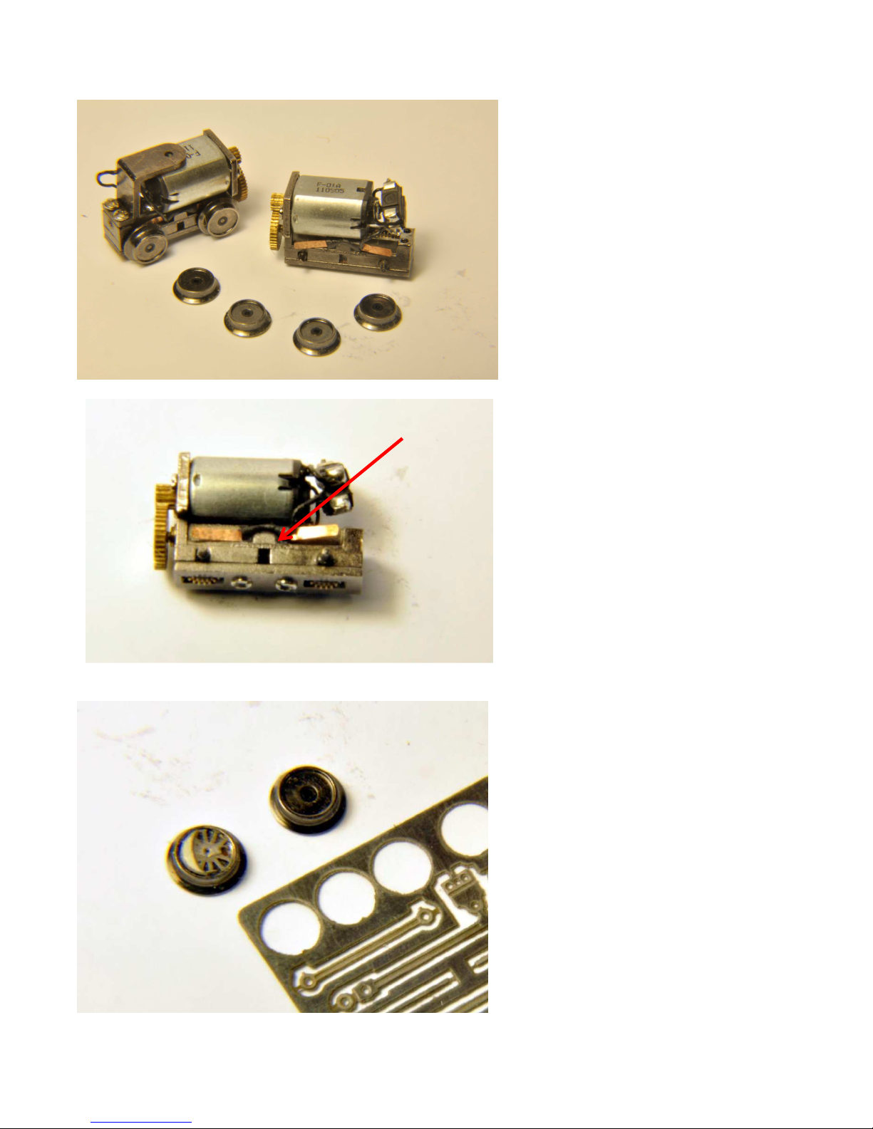
5
Cut driver center from etching
fret; glue driver center etch in
driver using SMALL drop of ACC
glue.
ASSEMBLY MANUAL – SEARAILS RR-XX – 0-4-0 SYTEAM LOCOMOTIVES
6
Drill with No. 76 (.5mm) drill.
WORK SLOWLY – the hole
intersects the stepped recess
for the insulating bushing – if
you are too aggressive, you will
break the drill bit off in the hole,
and then you are screwed!.
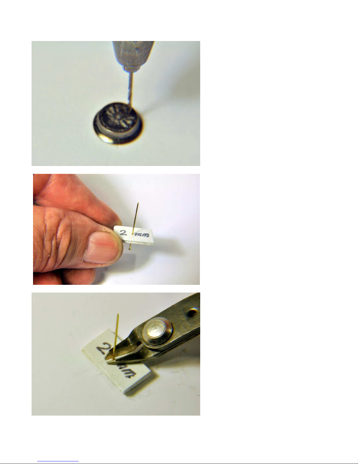
Cranks pins are to be made
7
from brass pins (supplied.) It is
suggested a jig be made from
laminated styrene as shown.
Place pins in jig, set jig on flat
8
surface, and cut 2mm long
crank pins
3/30/15 T R Knapp Model Engineering 3
ASSEMBLY MANUAL – SEARAILS RR-XX – 0-4-0 SYTEAM LOCOMOTIVES
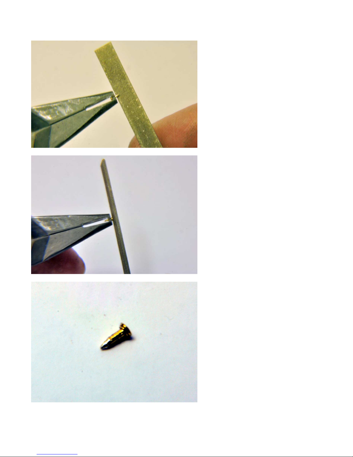
9
File end of crank pin into point.
File face of pin flat.
10
11
3/30/15 T R Knapp Model Engineering 4
Finished crank pin
ASSEMBLY MANUAL – SEARAILS RR-XX – 0-4-0 SYTEAM LOCOMOTIVES
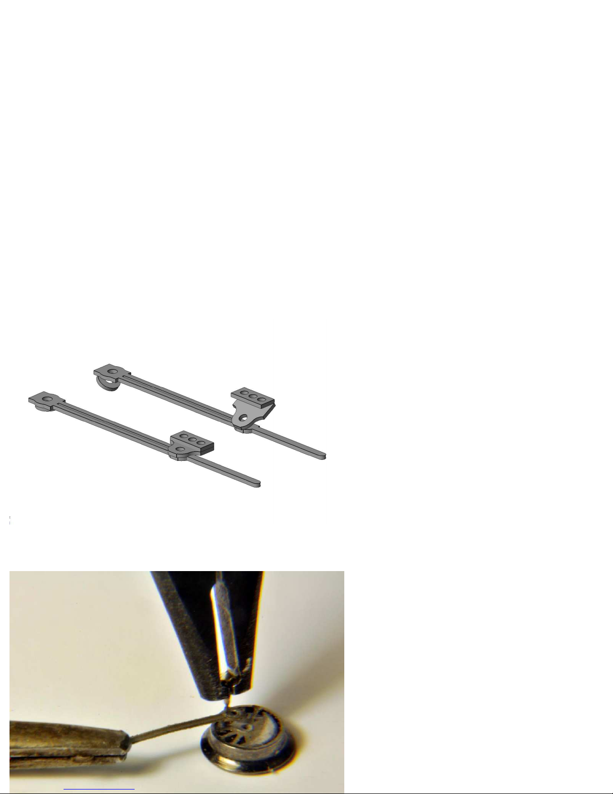
12
Cut main and side rods from
etching fret; fold main rod as
shown above, and secure with
CA adhesive.
13
Press crank pin into hole in
driver through hole in etched
rod.
ASSEMBLY MANUAL – SEARAILS RR-XX – 0-4-0 SYTEAM LOCOMOTIVES
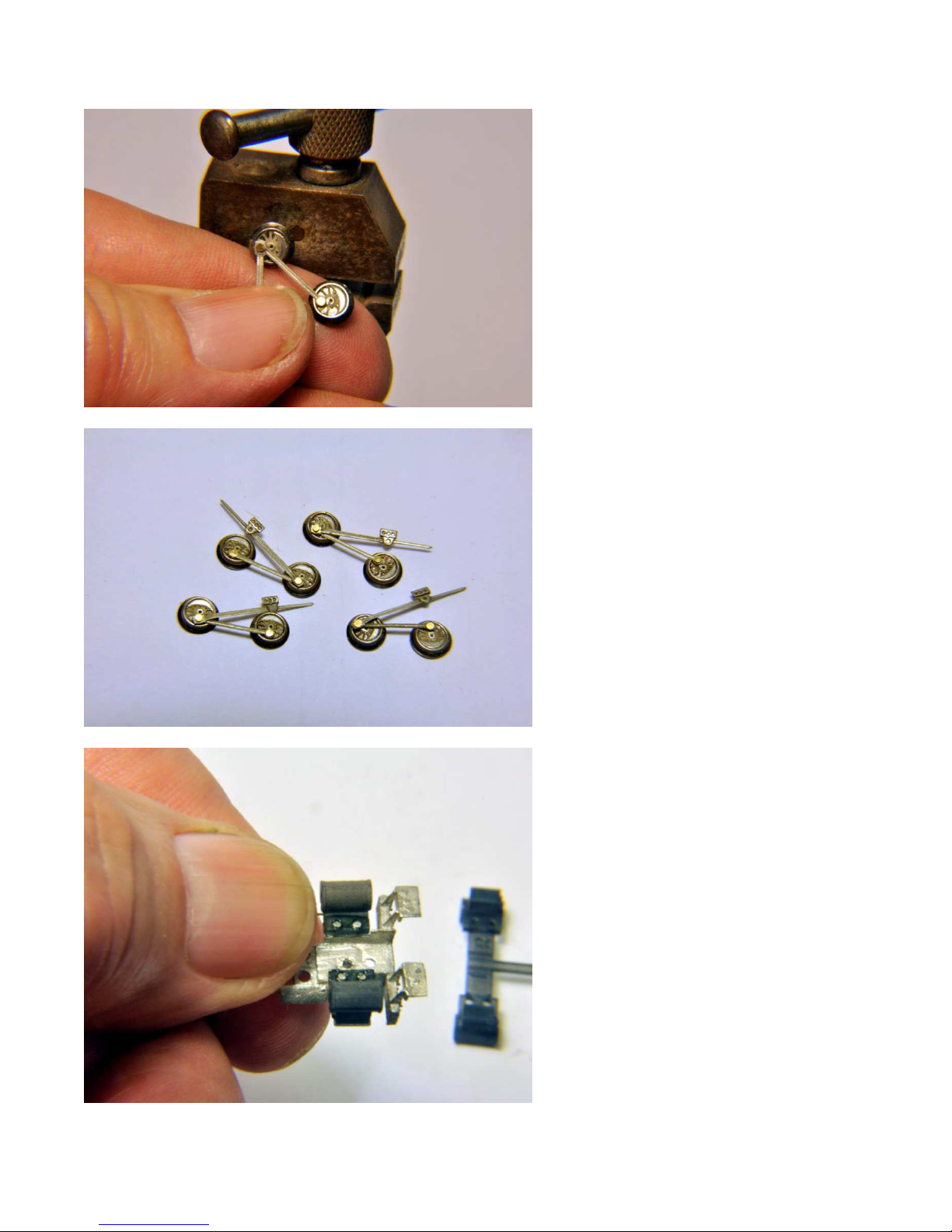
15
Crank pins pressed into drivers
through side rod and main rod;
there should be a little slop in
the assembly.
16
Rods and driver subassemblies;
note slight offset bent into main
rod to assure clearing crank pin
in front axle.
17
Press cylinder castings onto
pilot casting; DO NOT FORCE –
if too tight a fit, ream holes in
cylinders.
3/30/15 T R Knapp Model Engineering 6
ASSEMBLY MANUAL – SEARAILS RR-XX – 0-4-0 SYTEAM LOCOMOTIVES
18
Press crosshead guide supports
into chassis holes each side;
apply SMALL drop of ACC to
edge of hole to fix in place
19
Press drivers onto ends of axles
orienting each wheel to match
crankpin location; offset
opposite side by 90°.
3/30/15 T R Knapp Model Engineering 7
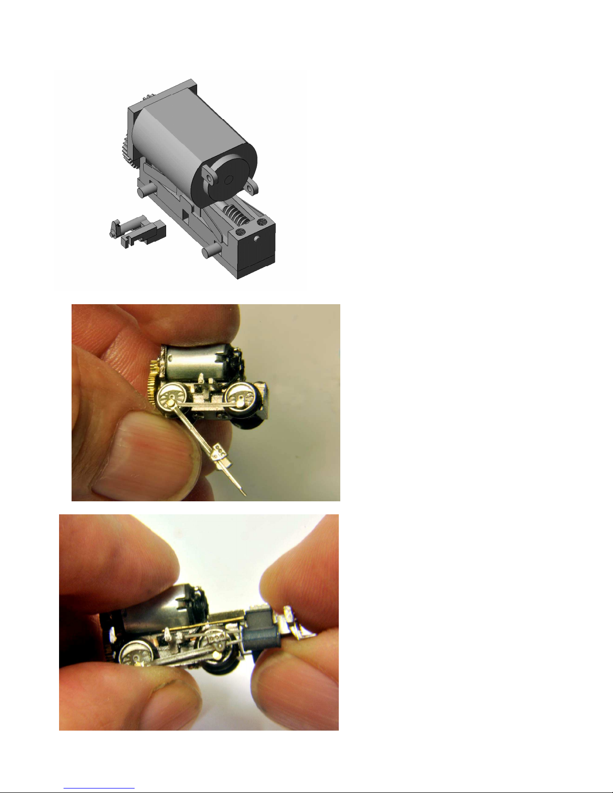
20
Slide piston rods into holes in
cylinders as pilot is fitted to front
of chassis. (Note: add etched
crosshead guide and wire
valve rod after step 20 at right.)

ASSEMBLY MANUAL – SEARAILS RR-XX – 0-4-0 SYTEAM LOCOMOTIVES
21
Fix front pilot in place with
screws; cut length of wire and
slip into valve rod hole on
cylinder casting and glue in
place at aft end; slip etched
crosshead guide into slots and
glue in place at aft end only.
12
Test ALL LED lamps with
N’gineering LED tester.
(N’gineering LEDs have colorcoded leads. Richmond
controls LEDs will need to be
marked after trimming to 1-1/2”
length.)
Solder LEDs together in pairs,
anode (+) to cathode (-).
3/30/15 T R Knapp Model Engineering 8
Solder LEDs together in pairs,
13
anode(+) to cathode (-)

ASSEMBLY MANUAL – SEARAILS RR-XX – 0-4-0 SYTEAM LOCOMOTIVES
Test paired LEDs
14
3/30/15 T R Knapp Model Engineering 9
15
Test run each PowerMAX! both
directions – set aside for repair
any units which run erratically,
unevenly or stall on turnout
points; remove the two screws
on the top of the chassis and
save for future use.
Lubricate with AeroCar ACT2112 or ACT-3753 at drive gears
and lay shaft bearings. Run to
work oil around friction
surfaces.
ASSEMBLY MANUAL – SEARAILS RR-XX – 0-4-0 SYTEAM LOCOMOTIVES
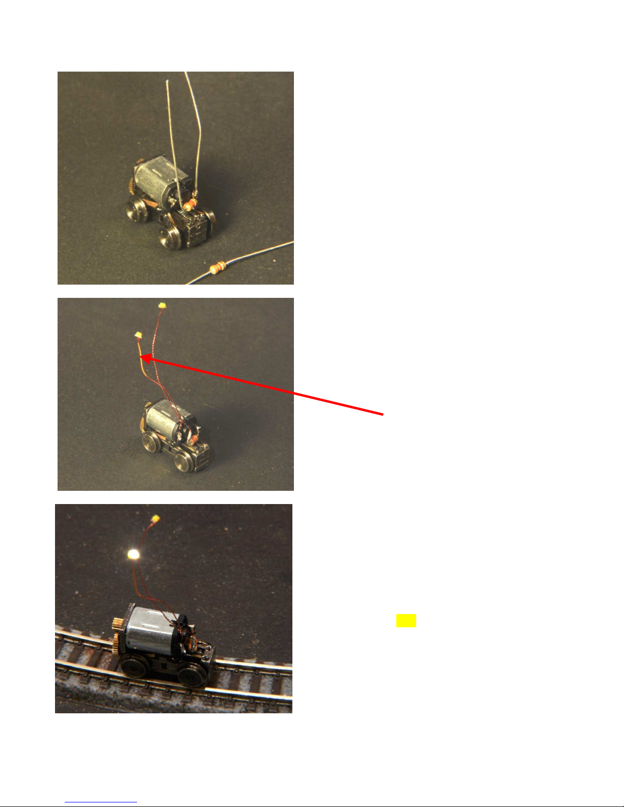
Bend resistor leads to form “U”,
16
and solder to one pole of
motor; trim leads as shown in
photo in step 17
Solder one lead from LEDs to
17
resistor, and one to opposite
pole of motor; make sure there
is adequate separation
between end of resistor and
motor pole. (Note: Unit in this
photo has already been tested
and color-coded per Step 18.)
Test again, and mark LEDs for
18
correct orientation; after
testing, insulate LED solder pads
with CA adhesive, Pacer
Canopy Glue or Gallery Glass
coating.
3/30/15 T R Knapp Model Engineering 10

ASSEMBLY MANUAL – SEARAILS RR-XX – 0-4-0 SYTEAM LOCOMOTIVES
19 Fit fuel tanks: for Version 1, slide
spigot into rectangular hole in
side of chassis; for Version 2,
hold chassis upside down in
jeweler’s vice, remove cover
plate screws, remove cover
plate and install new cover
plate and fuel tank casting
using original screws
21
22
Apply drop of CA adhesive in
20
headlamp opening from inside,
and slide rectangular LED into
rectangular opening, holding
until CA sets. (Use accelerator
to speed up this process.)
After both lamps are in place,
slip chassis up into body shell
carefully, taking care not to
pinch any of the fine LED leads,
and making sure the leads do
not foul the drive gears; attach
chassis with two 00-90 x 3/16”
flathead screws through fuel
tanks
Test run locomotive to make
sure lamps work correctly, and
locomotive is level on rails
Trim one MTL 905 coupler box
back to paper thin with motor
tool, or cut away completely;
mount this coupler to end of
locomotive with large lay-shaft
gears using MTL Z/Nn3 coupler
mounting screw, making sure
there is clearance between
coupler box and gear; attach
another MTL 905 to opposite
end of locomotive.
Test run locomotive again.
PAINTING OPTION 2: Mask
3/30/15 T R Knapp Model Engineering 11

ASSEMBLY MANUAL – SEARAILS RR-XX – 0-4-0 SYTEAM LOCOMOTIVES
wheels and headlamps and
paint after assembly.
After paint cures, remove
masking and Test run
locomotive again.
3/30/15 T R Knapp Model Engineering 12

ASSEMBLY MANUAL – SEARAILS RR-XX – 0-4-0 SYTEAM LOCOMOTIVES
F0090B188
RR-540 Parts List
EMD40 - Z (6.5mm gauge)
description part number qty source remarks
1 brass body casting 1 Udell
2 brass tank connector castings 1 Udell
3 PowerMAX-6.5 RR-153S 1 KK
4 resistor 3.3KEBK-ND 1 Digikey
5 pre-wired 0603 LEDs don't know number 2 N'gineering 1-1/2" wire leads
6 couplers (and screws) 002 02 021 2 MTL 1/2 package
7 screws 00-90 x 3/16
8 instructions insert
9 die-cut package insert
2
J I Morris Co 144 per package
3/30/15 T R Knapp Model Engineering 13
 Loading...