

Page 1
Page 2

Page 3

TABLE OF CONTENTS
Safety Information …………………………………………
Page 1
Introduction…………………………………………… Page 3
X-Bike™ Indoor Performance Bike
X-Biking™ Indoor Cycling Programmes
Installation and Adjustment…………………………… Page 4
Setting up the X-Bike™ Indoor Performance Bike
Assembling the X-Bike™ Indoor Performance Bike
Adjusting the X-Bike™ Indoor Performance Bike
Using your X-Bike™ Indoor Performance Bike……….. Page 9
Maintenance Instructions……………………………… Page 11
Parts – Removal and Replacement……………………... Page 15
Equipment and Technical Specifications……...……….. Page 24
Exploded views and Parts Id entification List ………….. Page 25
Product Features……………………………………….. Page 28
Warranty Statements and Registration Card……………. Page 32
Index ……………………………………… …………… Page 36
Page 4
SAFETY INFORMATION
WARNING
TO AVOID DEATH OR SERIOUS PERSONAL INJURY
• BEFORE beginning any fitness or conditioning program, consult with your physician
or health official. This will establish the proper conditioning or fitness program that is
appropriate for your age and physical condition.
• BE SAFE. Prior to commencing each X-Biking™ Ride answer these questions:
• Have you have been ill recently?
• Have you have felt dizzy recently?
• Have you have felt breathless recently?
• Have you have had a ny chest pain recently?
• Do you have an injury?
• Are you pregnant?
• Is there any reason why you think they should not exercise?
• Are you over 35 years old and do not exercise regularly?
• Have you have been told by a health practitioner that they shouldn’t exercise?
IF YOU ANSWER “YES” TO ANY OF THE ABOVE QUESTIONS YOU MUST
SEEK FURTHER ADVICE AND CLEARANCE FROM A MEDICAL
PROFESSIONAL PRIOR TO UNDERTAKING AN X-BIKING™ RIDE.
• ALWAYS read the user’s manual fully and follow all instructions, which were written
to ensure your safety and to protect the cycle.
Note for Club Owners: To ensure the proper use and safety of the X-Bike™ Indoor
Performance Cycle, make sure that all users have access to and refer to this manual. The
manual should be made available to all users.
• ALWAYS operate the X-Bike™ Indoor Bike only on a solid, level surface in a well lit
and well ventilated area. Make sure the seat and handlebars are securely fastened before use.
• NEVER allow children on the bike or allow children to play unsupervised near the bike.
Serious injury could occur due to a child’s curiosity or interest in the moving parts of the
cycle.
• ALWAYS ensure the bike is properly set up for your body type. The X-Bike™ Indoor
Bike offers up/down and fore/aft adjustments that are clearly marked to ensure a quick and
easy custom fit for each workout. Ensure that the rider compartment is securely tightened
before use.
• ALWAYS check the cycle before each use.
• NEVER use the cycle if it is not completely assembled or is damaged in any way.
• NEVER use an X-Bike™ Indoor Bike when ill or in a weakened condition.
1
Page 5

• NEVER exceed the weight limit for this bike. The weight limit for this bike is 300
pounds. Do not use the X-Bike™ Indoor Performance Bike if your body weight exceeds 300
pounds.
• ALWAYS wear proper attire and footwear that fully covers your feet. Long hair should
be tied back. Ensure that your laces are tucked into your shoes.
• ALWAYS warm up before beginning to exercise or at the start of a workout.
• ALWAYS use care when getting on and off the X-Bike Indoor Performance Bike.
Always wait until the pedals are completely stopped before removing your feet from the
pedals or dismounting. Do not stand or climb on the handlebars.
• ALWAYS ride or allow the X-Bike™ Indoor Performance Bike to be ridden only under
the supervision of a qualified X-Biking Instructor.
• ALWAYS keep hands away from moving parts and always ensure that hands are never
placed in a position where these is no rubber handlebar grip.
• NEVER overexert yourself or work to exhaustion. If you feel faint, dizzy, short of
breath, or if you have chest or other pains, STOP IMMEDIATELY! Consult your physician
before you continue.
• ALWAYS ensure that you have a water bottle with at least 300ml beverage and wear a
towel in the rear pocket of your riding top to absorb sweat from your body and the
handlebars.
• NEVER ride the X-Bike™ Indoor Performance Bike in a standing position at high
revolutions per minute (RPM).
• ALWAYS maintain your pelvis over the centre line of the X-Bike™ Indoor Performance
Bike.
• NEVER adjust the resistance of the flywheel and the resistance of the X-Bars™
Handlebar System when standing.
• NEVER use accessory attachments that are not recommended by the manufacturer –
such attachments might cause injury or damage to the bike and will affect the warranty of the
Bike.
• Please also note a s a gesture of courtesy to the next user and to maintain the high quality
of the X-Bike™ Indoor Cycle, please ensure that it is wiped down after each use.
• If any issues arise affecting the performance of the X-Bike™ Performance Bike, please
inform the X-Biking™ Instructor immediately and ensure that wear parts are checked
regularly.
• THIS SAFETY INFORMATION AND USER’S MANUAL GENERALLY DO
NOT REPLACE THE NEED TO BE ALERT AND TO USE YOUR COMMON
SENSE WHEN USING THE X-BIKE™ INDOOR PERFORMANCE BIKE!
2
Page 6

INTRODUCTION
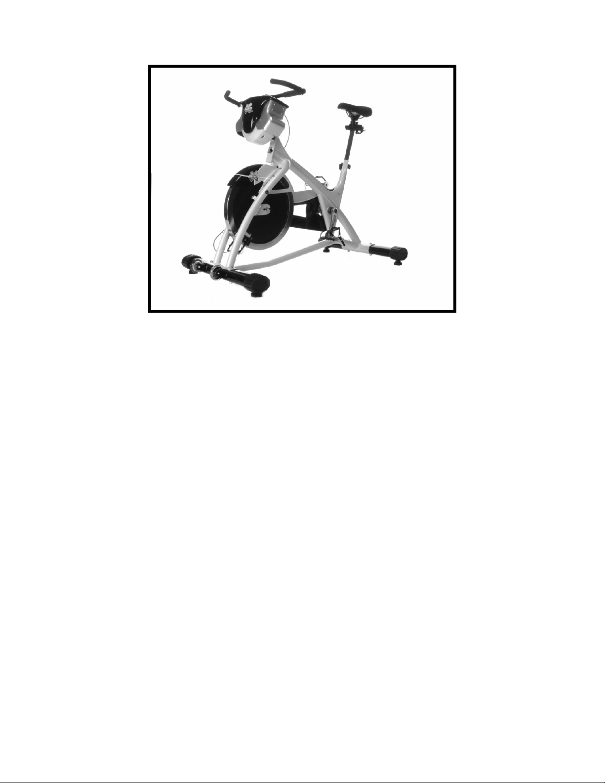
X-Bike™ Indoor Performance Bike
Congratulations on purchasing your Trixter Enabled X-Bike™ Indoor Performance Bike, one of
the most revolutionary cycles available to the fitness market. The X-Bike™ Indoor Cycle will
offer you an unrivalled whole body workout by introducing real bike upper-body movements. It
has been designed to simulate the real physiological demands experienced throughout the body
when cycling…an exercise often mimicked yet never equalled. Climbing out-of -the-saddle,
accelerating, and recovering are dynamic total-body actions for everyone riding bicycles
outdoors. Climbing steep hills and sprinting involve significant upper body and core muscle
recruitment to control the lower-body and the movement of bicycle beneath the rider. The XBike™ Indoor Cycle, featuring the X-Bars™ Handlebar System, provides an effective and
realistic means of accessing this unique level of fitness. Welcome to the X-Biking™ Indoor
Cycling revolution!
X-Biking™ Indoor Cycling Programs
Trixter's visionary X-Biking™ Group Cycling Programmes are ideal for people of all ages,
abilities, and fitness levels. Workouts are designed by experienced cycling coaches and elite
athletes to maximize the exercise benefits of the X-Bike™ Indoor Cycle. It’s the only total-body
cardiovascular group exercise workout based on a vibrant, engaging, and real outdoor sport mountain biking! During the immersive, fun-fit classes, you ride with a certified X-Biking™
Instructor to the sound of custom beats over a variety of simulated trails. Techniques like
"pumping" up a climb, banking the bars side-to-side to swoop through turns, and even coasting
on the X-Bike’s unique freewheeling platform provide essential and natural muscular
conditioning to dramatically enhance the rider's experience.
Before You Begin
Prior to leaving the manufacturing facility, your X-Bike™ Indoor Cycle was thoroughly
inspected and tested for proper operation. To minimize shipping damage, careful attention was
given to making the bike ready for shipment.
Dimensions of the X-Bike
In ch/lb mm/kg
Length 47.5 1205
Width 28.5 720
Height 41.5 1050
Weight 143 65
Your X-Bike™ Indoor Mountain Bike will have arrived in 1 carton. Upon arrival, fully inspect
the carton for damage. Point out any damage to the delivery person and have the delivery person
record the damage on the delivery paperwork. Contact the Customer Service Department to
report any damage (See details at the back of this Manual). Please follow these detailed
instructions and you will find that your new X-Bike™ Indoor Mountain Bike can be unpacked
and assembled with ease.
3
Page 7
INSTALLATION & ADJUSTMENT
SETTING UP THE X-BIKE Indoor Performance Cycle
WARNING
NOTE THAT THE SAFETY INFORMATION ON PAGES 1 & 2 SHOULD BE FULLY
READ AND UNDERSTOOD PRIOR TO ASSEMBLING THE BIKE
A. Remove the bike and components from the shipping carton
1. With assistance, move the box to the desired location in a well-lit and well
- ventilated area. Ensure that the carton is standing upright and remove the strapping
material. Ensure that you allocate sufficient floor space for the safe operation of the X-Bike
after it has been assembled.
2. Pull the cardboard edge along the top of the box and carefully remove and dispose of the
staples. Remove the boxes of contents enclosed with the frame.
3. Open each box and ensure that you have the following parts necessary to assemble your X-
Bike™ Indoor Cycle:
• X-Bike™ Indoor Cycle Frame including Seat Post and Handlebar Assembly
comprising Gripshift System and Hand Grips.
• Separate Box with X-Bars™ Handlebar System Head Unit.
• Separate box with front base leg including feet.
• Separate box with rear base leg including feet.
• Separate package with bottom X-Bar Cover (if this has been left off the assembly).
• Separate package with Seat including Seat Slider Rail
• Separate Box with the following
o Head stock adaptor
o Bag with Head stock adaptor bolts
o Quick Release for seat slider
o Bolts, Nuts and Washers for legs (4sets)
o Handlebar clamp including bolts
o Pedals x 1L & 1R
o Bar Ends x 1L & 1R
o Square rubber gator for Frame head tube
• Separate package with the User’s manual
4
Page 8
B. Assembling the Bike
All references to the right or left side and to the front or back are made as if you were sitting on
the exercise bike ready for use. For example, the chain guard is on the right side of the bike and
the flywheel is at the front.
1. You will need the following tools and materials to assemble the X-Bike™ Indoor
Performance Bike.
• Box knife
• 13mm, 15mm (Pedal Spanner) and 17mm spanners
• 4mm, 5mm and 6mm (Long) Hex Head Wrenches
• Can of PTFE (PolyTetraFlouroEthylene) spray.
2. With the help of an assistant, lift the bike frame out of the carton and remove all protective
packaging.
3. Fit the legs onto the frame ensuring that the leg with the wheels is fitted to the front and the
leg without wheels is fitted to the back. Make sure that the wheels are facing towards the
front and that the feet are facing downwards. Insert the M10 bolts provided facing
downwards ensuring that you have a washer above and below the leg. Fit the M10 Nut and
tighten securely.
Note: If you are having difficulties threading the nut onto the bolt, with assistance prop up
the base leg and the frame on wooden blocks to gain easier access to the nut underneath.
4. Adjust the 4 leveller feet to ensure that each corner is fully supported on the floor. Once
adjusted, lock the position by tightening the lock wing nut inside the leveller feet.
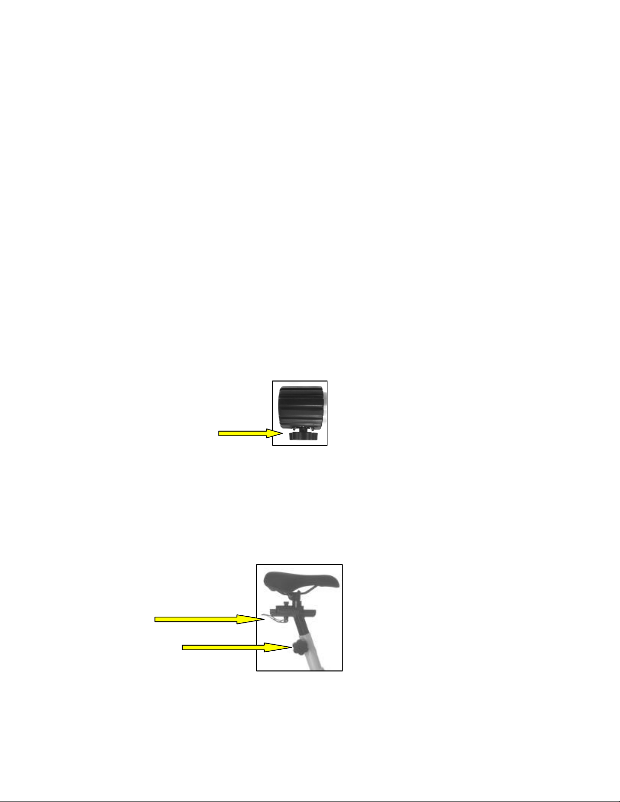
Leveller Foot
5. Slide the seat post into the seat tube at the rear of the frame and tighten the adjustable quick
release knob until you are ready to set the height position. Slide the seat assembly onto the
seat post and fit the quick release handle provided from the bottom upwards. Fit the
thumbscrew at the top of the quick release bolt to secure until you are ready to set the fore/aft
position.
Seat Fore/Aft Adjust Lever
Seat Height Adjuster Knob
6. To fit the X-Bars™ Handlebar System Head unit, you must first fit the adaptor. This will
give access to the main X-Bars frame internally. The adaptor should be fitted so that the head
post is facing downwards and towards the rear of the assembly.
5
Page 9
Insert the 4 x M8 bolts provided through the base plate of the X-Bars into the adaptor from
front towards the rear, and ensure that a washer is fitted on both the nut and bolt ends.
Tighten securely. Fit the bottom cover using the 2 x M4 Hex head screws provided.
7. Before inserting the X-Bars system into the Frame Head tube, place the square rubber gator
on the top on the head tube. The X-Bars System assembly is inserted through the rubber
gator and into the head tube with the head of the assembly facing towards the front of the
bike. Tighten the adjustable quick release knob until you are ready to set the head height
position.
Note the orientation of the
Handlebar and Bar Ends.
Height Adjuster Knob
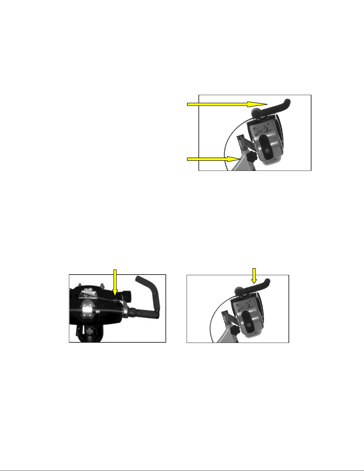
8. Loosen the Handlebar clamp on top of the X-Bars Handlebar System Head Unit to gain
access for the handlebar fitment. Place the handlebars into the clamp so that the bar ends are
facing towards the front of the bike and the Grip-shift™ is on the right hand side of the bike.
Place the marked clamp area of the handlebars centrally in the clamp to ensure to provide
maximum grip from the clamp. Refit the clamp and tighten the bolts diagonally to ensure
there is an even pressure applied to all four bolts. Just before the clamp takes pressure, adjust
the orientation of the bars so that the exit route of the Grip -shift™ has approximately 5mm
(1/4”) clearance with the top of the Cover. Tighten securely.
Note orientation of handlebar and position of Grip-shift™
9. Fit the pedals, which are marked as if you are seated on the bike, “R” for right and “L” for
left. Carefully thread the right pedal in the crank with your fingers – do not cross thread the
pedal in the crank arm. Use a size 15 wrench tool to tighten the pedal. Repeat the step for the
left pedal. Do not over-tighten.
Note: The left pedal is reverse-threaded.
10. Using the PTFE spray, direct the nozzle into the wear pad material and apply generously to
ensure the pads are well lubricated.
11. Use a soft clean cloth to wipe off dust that may have accumulated during shipping.
12. The X-Bike™ Indoor Cycle is now ready to set up for use.
6
Page 10
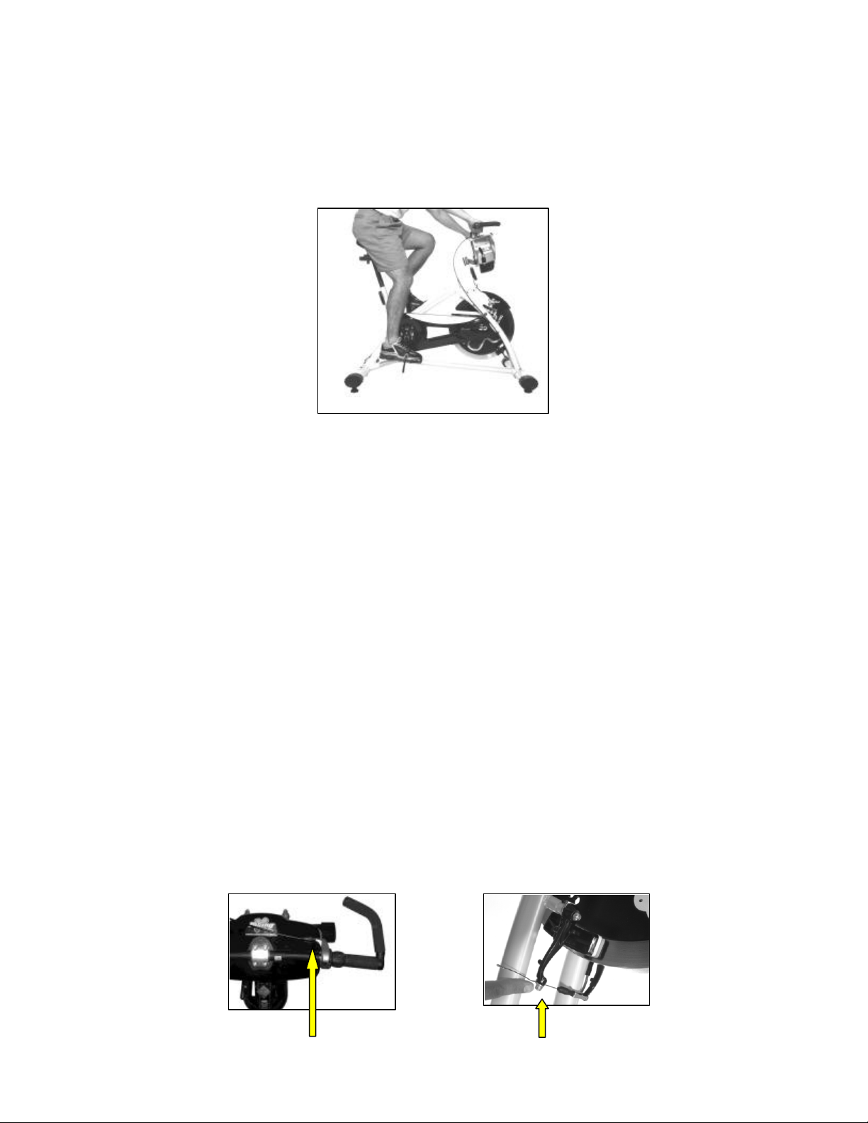
Adjusting the Bike
Seat Adjustment
1. Rotate the pedals so that one of the pedals is in the upward position.
2. Place your foot in the toe clip of the pedal closest to the floor and mount the bike. Ensur e that
the ball of your foot is over the centre of the pedal. Your leg should be slightly bent at the
knee as shown in the picture below.
3. If your leg is too straight or your foot cannot touch the pedal, you will need to lower the seat.
If your leg is bent too much, you will need to raise the seat.
4. To adjust, dismount the bike and release the quick release knob for the seat height
adjustment. Once loosened you may slide the seat post up or down as necessary. When the
seat is in the desired position, reapply the quick release knob to lock the position. Note the
final position mark on the seat stem for future use.
5. Adjusting the fore or aft allows for better fit. To adjust, dismount the bike and release the
quick release lever under the seat and slide the seat forward or backward as desired. Re -apply
the quick release clever to lock. Note the final position mark on the seat stem for future use.
Adjusting the Flywheel Resistance
The X-Bike™ Indoor Performance Bike should arrive with the resistance system set up on
the handlebars already, and may only require minor adjustment after the handlebar assembly
has been fitted onto the X-Bars™ System Head Unit. Minor adjustment can be achieved by
turning the adjuster wheel at the cable exit on the Grip -shift™ either clockwise or counterclockwise depending on whether it need to be increased or decreased.
If the resistance needs more adjustment than is available in the minor adjustment block, it can
be set up as follows:
1. Turn the minor adjuster wheel on the Grip-shift™ fully counter-clockwise so that there will
be sufficient cable in the minor adjustment block for future regular checks
7
Page 11

Minor Cable Adjuster Cable Release Bolt
2. Using a 6mm Hex key, loosen the bolt at the bottom of the V-Brake to release the cable for
adjustment.
3. Turn the Grip -shift™ fully clockwise to the minimum resistance setting – position 1. Using
one hand, compress the 2 pads of the V-Brake to just make contact with the flywheel. Pull
the excess cable until it is tight in the cable clamp. Retighten the bolt to secure the cable.
4. The resistance is set, when the minimum setting is free from contact with the flywheel and
position 2 just begins to make slight contact. Minor adjustment can be achieved by screwing
the minor adjustment wheel where the cable exits from the Grip -shift™.
Handlebar (Bar Height) Adjustment
1. If you own a road or mountain bike, this position can be taken from your chosen set up. Place
a straight edge ruler on top of your bikes saddle and extend it over the handlebar, making
sure that the ruler is level or parallel with the ground. Measure the distance from the bottom
edge of the ruler to the top of the handlebar and replicate this measurement on the X-Bike™
Indoor Cycle.
2. To adjust, dismount the bike and release the quick release knob on the head tube for the
handlebar adjustment. Raise or lower the X-Bar™ System headstock until the required
measurement has been achieved. Reapply the quick release knob to lock. Note the final
position mark on the handlebar stem for future use.
3. If you do not own a bike and are setting the height up for the first time it is suggested to set
the handlebars at the same height as the seat for a datum and then try different heights to get
the arrangement most suitable for you.
Pedal Strap Adjustment
1. Place the ball of each foot on the pedal and in the toe clip such that the ball of the foot is
centred over the pedal spindle (centre of the pedal)
2. Rotate one foot to within arms reach and pull up on the toe clip strap. Repeat for the other
foot.
3. Keep your knees over your foot as you pedal.
8
Page 12
PLEASE REFER TO THE SAFETY INFORMATION ON
THESE GUIDELINES ARE DIRECTED
TO YOU AS THE OWNER OF THIS EXERCISE EQUIPMENT AND YOU
USING YOUR X-BIKE INDOOR PERFORMANCE BIKE
General Exercise Guidelines
You should only undertake an exercise program using an X-Bike™
Indoor Cycle, under the supervision of a qualified X-Biking™ Instructor.
Trixter, Its Distributors and Sales Agents do not accept responsibility for
any injury, which may occur whilst riding unsupervised and without
proper instruction.
Pedalling
1. Obtain a complete physical examination from your medical doctor and ensure to follow
the recommended training profiles suitable for your current health status.
2. The speed and duration of your exercise program should always be subject to how you
feel. Never permit peer pressure to exceed your personal judgement while exercising.
3. When working out for the first time, start out slowly for a minimum of five minut es.
After your muscles have warmed up, gradually increase the pedalling rate and/or
resistance to a speed that allows you to attain a comfortable training threshold. If you
have access to a heart rate monitoring device, you can set your speed and resistance that
allows you to attain your target heart rate zone.
Pumping the X-Bars
1. Once you are confident with the pedalling motion of the X-Bike, set the flywheel
resistance to a comfortable setting and get into a standing position on the bike while
continuing to pedal at a steady rate. To familiarise yourself with the pumping motion, set
the handlebar resistance to minimum by twisting the handlebar resistance knob at the side
of the X-Bars™ Handlebar System fully counter-clockwise and begin to “pump” the bars
left and right in time with your pedalling rhythm in a similar fashion as if you were riding
a bike. This natural cycling movement comes by ensuring that your right arm and left leg
go down at the same time and your left arm and right leg go down at the sa me time.
2. Overweight individuals should be particularly cautious when using the equipment for the
first time. Even though such individuals may not have histories of serious physical
problems, they may perceive the exercise to be far less intense than it really is, resulting
in the possibility of overexertion or injury.
3. Although all equipment manufactured by Trixter has been thoroughly inspected by the
manufacturing facility prior to shipment, the purchaser is responsible for proper assembly
and installation of the X-Bike indoor performance bike.
WARNING
SAFETY FIRST –
PAGES 1 & 2 OF THIS MANUAL.
SHOULD INSIST THAT ALL USERS FOLLOW THE SAME GUIDELINES.
YOU SHOULD MAKE THIS MANUAL AVAILABLE TO ALL USERS.
9
Page 13
Mounting and Dismounting
Once sitting comfortably on the Bike, make sure to tighten each toe strap securely before
commencing exercise. Dismount the bike by first loosening each toe clip and then
removing your feet from the pedals. Carefully step off the bike.
Your First Workout
Basic Instructions
Once an instructor has helped you to properly adjust the bike to your body size and you are
sitting comfortably on the bike, slowly begin pedalling. Allow your hands to rest comfortably on
the handlebars.
WARNING
If at any time during your workout you feel any chest pain, experience severe muscular discomfort, feel
faint, or are short of breath, STOP EXERCISING IMMEDIATELY. If the condition persists, you should
consult your medical doctor immediately.
Pedalling Resistance
Pedalling resistance is controlled by the turning of the Twist-grip™ located on the right side of
the handlebar. The minimum resistance setting is located with the Twist-Grip™ turned fully
clockwise – increasing to a maximum Resistance when the Twist-Grip™ is turned fully counterclockwise. It may be adjusted at any time during exercising by turning the Twist-grip™ to the
desired resistance setting.
X-Bar™ Handlebar System Resistance
Handlebar resistance is controlled by the knob located at the end of the resistance damper on the
right side of the head section. There are seven settings from minimum to maximum. The
resistance can be adjusted at any time by twisting the knob anti-clockwise for minimum and
clockwise to maximum setting.
* Your instructor will advise you on the correct use of the X-Bars™ System.
10
Page 14
MAINTENANCE INSTRUCTIONS
Helpful Hints
The safety level given by the design of X-Bike™ Indoor Performance Bike can only be
maintained when the equipment is regularly examined for damage and wear. Inoperable
components should be replaced or the equipment should be put out of use until it is repaired.
Read all maintenance instructions before beginning work.
All references to the right or left side and to the front or back are made as if you were sitting on
the exercise bike ready for use. For example, the chain guard is on the right side of the bike and
the flywheel is on the front.
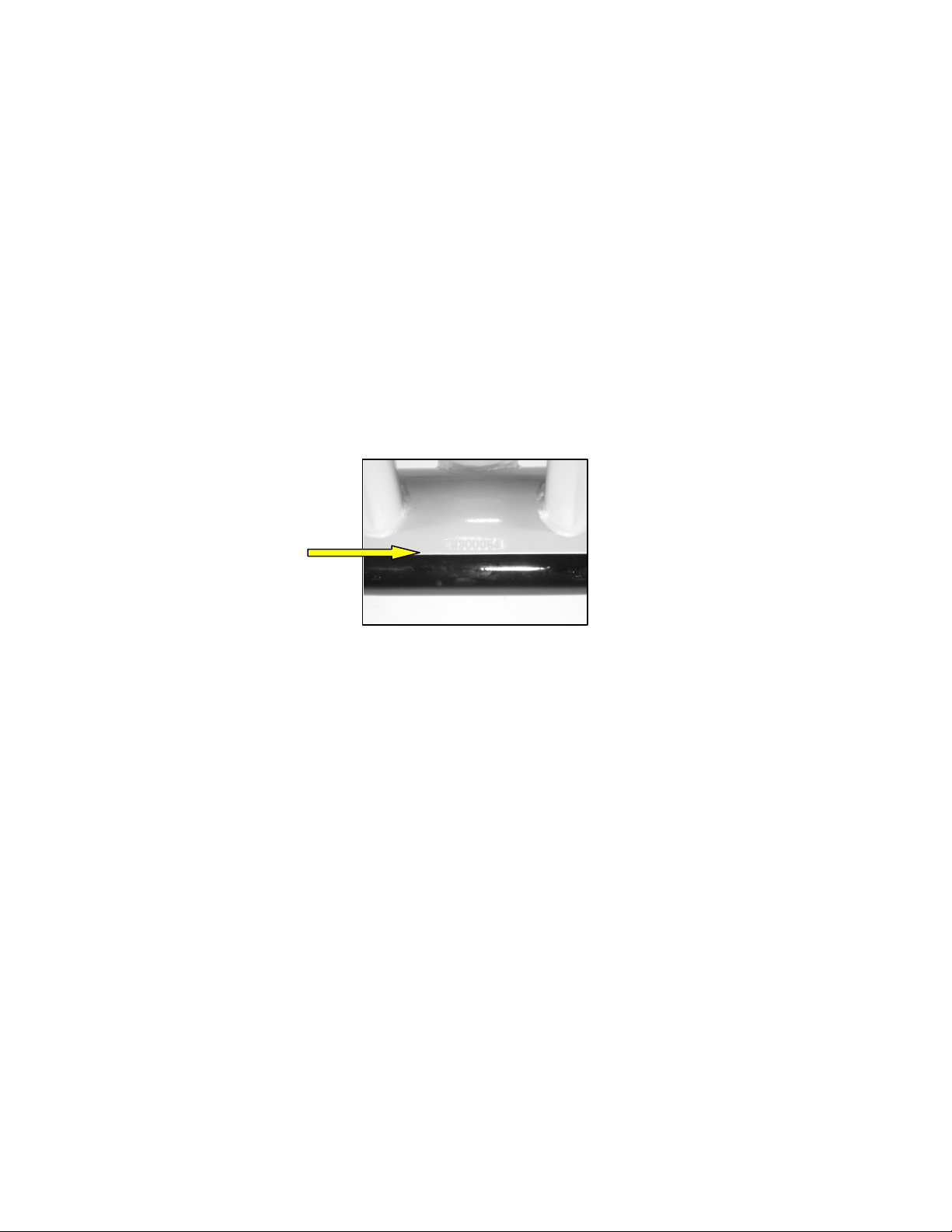
For identification purposes, the serial number of the X-Bike™ Indoor Cycle is located on the
front support Leg and the serial number for the X-Bars™ System is located internally on the
main base plate, which can be accessed by removing the bottom cover.
Front of Bike Frame
Serial Number
Tool List
The following tools will be needed to carry out service and maintenance:
• Spanners including 10mm, 13mm, 15mm (Pedal Spanner) and 17mm
• Metric Hex Keys (long) set including 2.5, 3, 4, 5, 6, and 8mm.
• Genuine X-Bike BB Lock Ring removal tool.
• Phillips screwdriver
• Bicycle crank arm puller
• Bottom Bearing Cup tool
• Shimano® compatible bottom bracket tool and 1/2 “ driver
• Trixter Spring Fitting tool
11
Page 15
Preventative Maintenance
Refer to the appropriate Parts Removal and Replacement section on PAGES 19-28 for all
disassembly and assembly instructions. If you experience any problems, contact your Matrix
Fitness Systems service department (Details found at www.trixter.net).
CHECKLIST OF ROUTINE MAINTENANCE REQUIREMENTS
Daily
1.
Wipe Down the X-Bike Indoor Cycle
2. Inspect for loose components and tighten where necessary
Weekly
1. Inspect the Wear Pads for excessive wear or dryness
2. Lubricate the Flywheel
3. Lubricate the Drive Chain
4.
Clean the X-Bars System and X-Bike Indoor Cycle
Monthly
1. Inspect the Chain Tensioning
2.
Inspect the X-Bars System damper performance
3.
Inspect the X-Bars System ‘Return to Zero’ Performance
4.
Inspect the rigidity of the X-Bars System to check for looseness in the mechanism.
5. Inspect the Centre Slider for wear
6. Inspect the Damper slider for wear
7. Inspect the seat and handlebars post adjustment for secure height adjustment tightening
Daily
1. Wipe down the X-Bike after each use to remove sweat and moisture. Use soap and water,
or a diluted non-abrasive domestic cleaner solution. Rinse to remove detergent residue
and then dry off.
2. If the bikes are used frequently in group exercise sessions, inspect for loose components
such as pedals or cranks prior to commencing the next class. Tighten up any loose parts.
Weekly
1. Inspect the resistance wear pads for excessive wear or dryness. If necessary lubricate the
pads with GT-85 or another PTFE based lubricant. As the pads wear with use, it will be
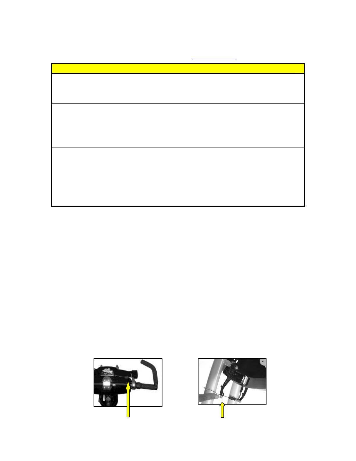
necessary to adjust the resistance cable to compensate. The resistance cable can be
adjusted as follows;
o Turn the minor adjuster wheel on the Grip-shift™ fully clockwise so that there
will be sufficient cable in the minor adjustment block for future checks.
o Using a 6mm hex key, loosen the bolt at the bottom of the V-Brake to release the
cable for adjustment.
12
Page 16
Minor Cable Adjuster Cable Release Bolt
o Turn the Grip -shift™ fully clockwise to the minimum resistance setting. Using
one hand, compress the 2 pads of the V-Brake to just make contact with the
flywheel. Pull the excess cable until it is tight in the cable clamp. Retighten the
bolt to secure the cable.
o The resistance is set, when position 1 or minimum setting is free from contact
with the flywheel and position 2 just makes contact. Use minor adjustment if
required.
o If the pad thickness is reduced to less than 4mm, they need to be changed. (See
Pad Changing instructions in Parts – Removal and Replacement)
2. Wipe down the flywheel with WD-40® or equivalent light oil spray. This lubricant will
clean the surface of the flywheel and help prevent rust.
3. Lubricating the chain – Using a spray can with an extension nozzle; you can gain access
to the chain from the front of the chain guard with general light maintenance oil.
4. To keep the X-Bike looking new, wipe the genera l bodywork of the X-Bike and X-Bars
with a clean damp cloth. Use conventional dish washing detergent but never use abrasive
materials to clean the bike. Be certain to wipe off all traces of perspiration when you are
finished as it contains salt and other corrosive substances that can damage surfaces and/or
leave a white residue.
5. If you should need assistance or service, contact your service department
(See details at www.trixter.net)
Monthly
1. Chain Tensioning
Inspect the chain for tensioning by rotating the crank to drive the flywheel forward. Do
this motion in ¼ turns to assess if there is free play between the crank and the flywheel.
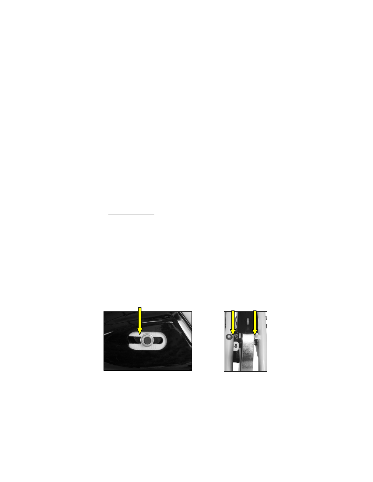
Tensioning the flywheel is achieved by adjusting the bolts in the front forks of t he bike,
which set the position on the flywheel axle in the frame. To Tension the chain, undo the
axle nuts on either side of the flywheel enough to release the grip and allow the flywheel
to move.
Axle Position Markings Chain Adjusting Bolts
Turn the chain tensioning bolts on both sides of the frame by the same amount to ensure
correct alignment. Continue to adjust in small amounts until the chain slack is eliminated
and the flywhee l can rotate freely without pulling the pedals around with it.
2. X-Bars Handlebar System Damper Performance
13
Page 17
Examine the damper for smoothness and consistency of movement. This is determined by
testing the movement in the handlebars firstly in minimum and then in maximum
resistance setting.
a. Air Cavitations - At minimum, the movement should be light and smooth
without the presence of the sound of air cavitations. This would be a sound you
could expect with the presence of tiny air bubbles in the system, which will affect
the consistency and quality of resistance. If cavitations are present, the damper
should be replaced. See replacing the damper in Parts – removal and replacement
section.
b. Sticking - At maximum setting, the handlebars should move from fully left to
fully right consistently without any sticking action. Over time, the moving parts
can wear and lead to resistance tolerances being affected. If the movement in the
handlebars experiences sticking, the damper should be replaced. See replacing the
damper in Parts – removal and replacement section.
3. X-Bars Handlebar System ‘Return to Zero’ Performance
Examine the action of the ‘Return to Zero’ springs on the handlebar system by setting the
resistance at maximum. Move the bars to the extreme right and r elease and then extreme
left and release. At this setting the mechanism should return close to centre under its own
action. If it is found that the handlebars remain unreasonably fixed to one side or the
other, the springs will need to be replaced. See rep lacing the ‘Return to Zero’ springs in
Parts – removal and replacement section.
4. Looseness in the X-Bars Handlebar Mechanism
a. Mechanism Hardware - Examine the handlebar system assembly for general
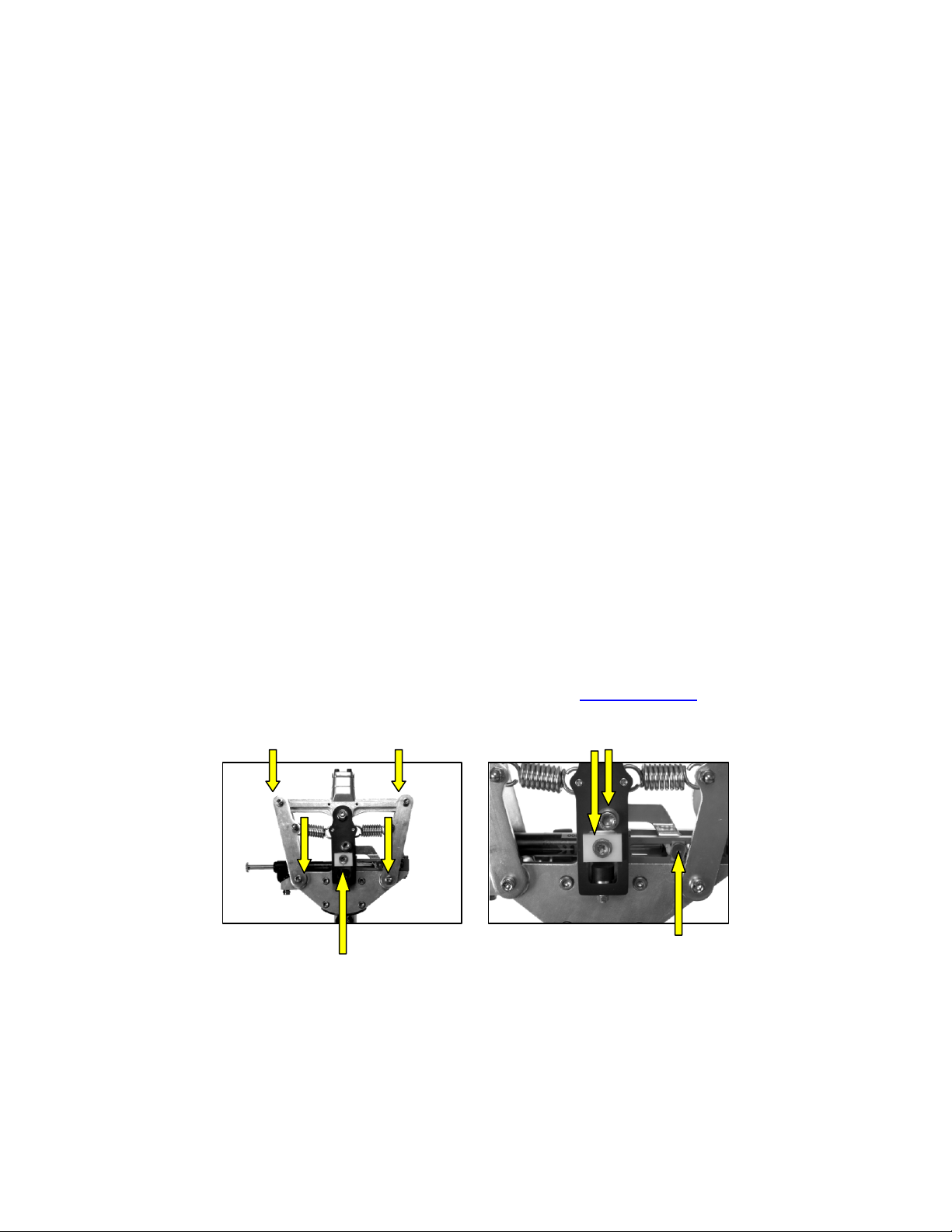
mechanism looseness. Check all 4 main pivot bolts, the 2 large bolts in the centre
of the assembly, and the main damper pin through the end of the damper. If any
looseness is present, tighten before reassembly. In the event that any of these bolts
have been found to be loose, they should be checked again at the next weekly
maintenance routine and if they have re-loosened, please contact your authorised
dealer. (Details for your closest dealer found at www.trixter.net)
Main Pivot Bolts Centre Bolts
Centre Slider Damper Slider
b. Slider wear – There are three sliders in the mechanism, 1 in the centre swinger
and the other 2 running in the damper rails. If the clearance between these sliders
and the rails in which they run exceeds 1.5mm, they should be replaced.
5. Height Adjustment
14
Page 18

Dryness or prolonged use may cause the height and reach adjustments for the bars and
seat to become tight. If this is the case, the sliding assembly should be removed from the
frame and have a smear of light duty grease applied along the sliding surface before
reassembly. Similarly, apply some light grease to the clamping assembly to ensure it does
not seize up. Clean off excess ive grease before reassembly.
15
Page 19
PARTS – REMOVAL AND REPLACEMENT
WARNING:
It is vitally important to keep the X-Bike Indoor Cycle properly maintained but if you are
unsure about any of the procedures for the removal or replacement of parts, you are
recommended to contact your authorised dealer.
NOTE: When carrying out any service or maintenance procedures, it is vital to ensure that
ALL hardware has been fully tightened and the assembly is returned to its original assembly
state prior to allowing the X-Bike Indoor Cycle to be used. If in doubt, contact your
authorised dealer.
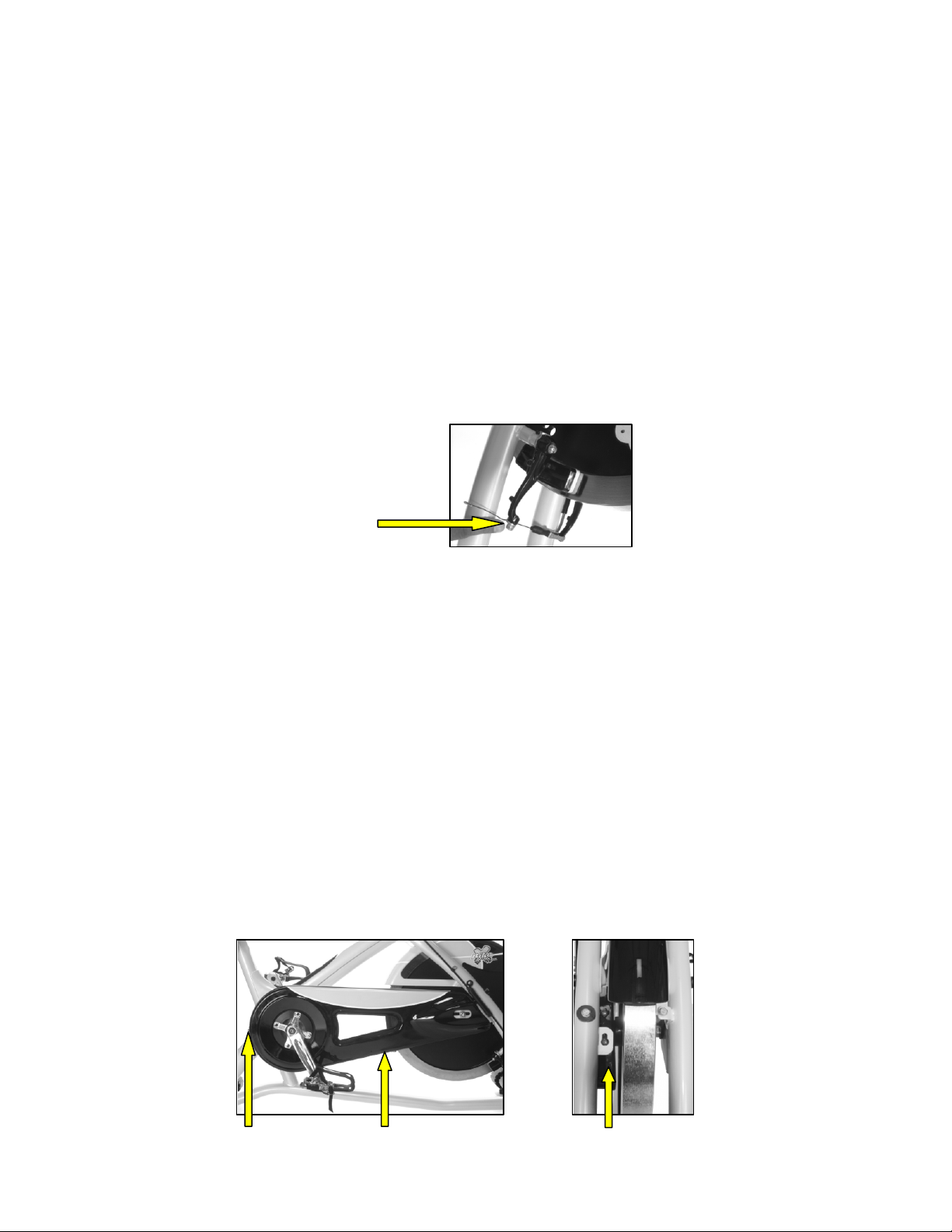
Replacing the Resistance Pads
1. If the pad thickness is reduced to less than 4mm, they need to be replaced.
2. Using a 6mm hex key, loosen the bolt clamping the resistance cable to re lease the V-
brake mechanism.
Cable Release Bolt
3. Remove the screw at the back of the pad housing to release. Drop the pad out of the
assembly.
4. Fit new pad into the V-Brake assembly on both sides. Refit the screws complete with the
spring and washers. Tighten to within 2 full turns from the end.
5. Turn the Grip -shift™ fully clockwise to the minimum resistance setting. Using one hand,
compress the 2 pads of the V-Brake to just make contact with the flywheel. Pull the
excess cable until it is tight in the cable clamp. Retighten the bolt to secure the cable.
6. The resistance is set, when the minimum setting is free from contact with the flywheel
and position 2 just makes contact.
Removing the Chain Guards
Outer Guard
1. Remove the 3 bolts holding the outer guard to the frame. These bolts are 1 at the rear, 1
underneath and 1 between the flywheel and the right hand fork (Left if you look into the
bike from the front where it is accessed)
16
Page 20
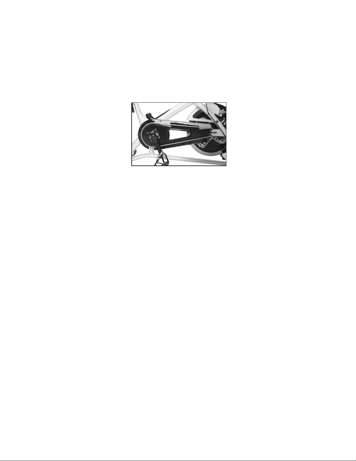
Bolt 1 Bolt 2 Bolt 3
2. Turn the right hand crank arm vertically downwards as this allows the outer guard to be
removed more easily.
3. Ease the outer guard away from the inner guard taking care not to damage the pro tective
seals between it and the inner guard. Once free, remove the seal from the bottom of the
cover to allow a little more room for removal.
4. Carefully manoeuvre the guard, bottom first away from the frame and orientate it to fit
around the crank and the pedal. Once removed, you have full access to the drive train.
5. Refitting the chain guard is simply to carry out actions 1 to 4 in reverse.
Inner Guard
1. Follow procedure for “removing the pedal crank arms” below.
2. Undo 3 bolts fastening the inner guard to the frame.
3. To refit follow steps 1 and 2 in reverse.
Removing the Flywheel
1. Follow the procedures shown above for removing the chain guard.
2. Loosen the nuts on either side of the flywheel axle enough to allow the flywheel to move
freely in the axle slide on the frame.
3. Turn the 2 chain tensioning bolts on the front forks counter-clockwise until they are fully
removed from the flywheel bracket.
4. The flywheel axle can then be removed from the slide taking care to support its’ weight
when it drops out (40 pounds/18.2kg). Care should also be taken not to drop the flywheel
onto the frame below, as the paintwork will be damaged.
5. The chain can now be eased off over the front chain sprocket.
6. The flywheel is replaced by following steps 1 to 5 in reverse.
7. To Tension the chain, turn the chain tensioning bolts on both sides of the frame by the
same amount to ensure correct alignment. Continue to adjust in small amounts until the
chain slack is eliminated and the flywheel can rotate freely without pulling the pedals
around with it.
Replacing the Chain
1. Follow the procedures shown above for removing the outer chain guard.
2. Follow the procedures shown above for removing the flywheel.
3. Replace with new chain in a similar fashion and repeat the procedures above in reverse to
re-assemble.
4. To Tension the chain, turn the chain tensioning bolts on both sides of the frame by the
same amount to ensure correct alignment (Check the alignment by counting the marks on
the flywheel bracket on both sides of the frame). Continue to adjust in small amounts
17
Page 21
until the chain slack is eliminated and the flywheel can rotate freely without pulling the
pedals around with it.
Replacing the Handlebars
1. NOTE: Your X-Bike Indoor Performance Bike has been fitted with 580mm long
handlebars as standard. You must ensure that the new bars to be fitted are within the
recommended maximum length of 580mm with a tube wall thickness not less than
3.2mm and are the correct diameter 25.4mm at the clamping section.
2. As you will probably intend to use the e xisting Grip-shift™ mechanism, you should first
remove these parts from the existing assembly.
3. Remove the bar-ends by using a 6mm hex key to loosen the bolt under the clamp.
4. Carefully prise inside the rubber handlebar grips with a small flat head screwdriver and
spray some WD-40© or equivalent light oil spray. Ease the grips from either end of the
handlebars.
5. Using a 6mm hex key, loosen the 4 bolts from the handlebar clamp on the top of the X-
Bars Handlebar System to release the grip on the handlebar.
6. Twist the handlebar to expose the bolt holding the Grip -shift™ and using a 2.5mm hex
key loosen this bolt. Slide the assembly off the end of the bars.
7. Remove the 4 bolts from the handlebar clamp on the top of the X-Bars Handlebar
System. Remove the bars fro m the clamp housing.
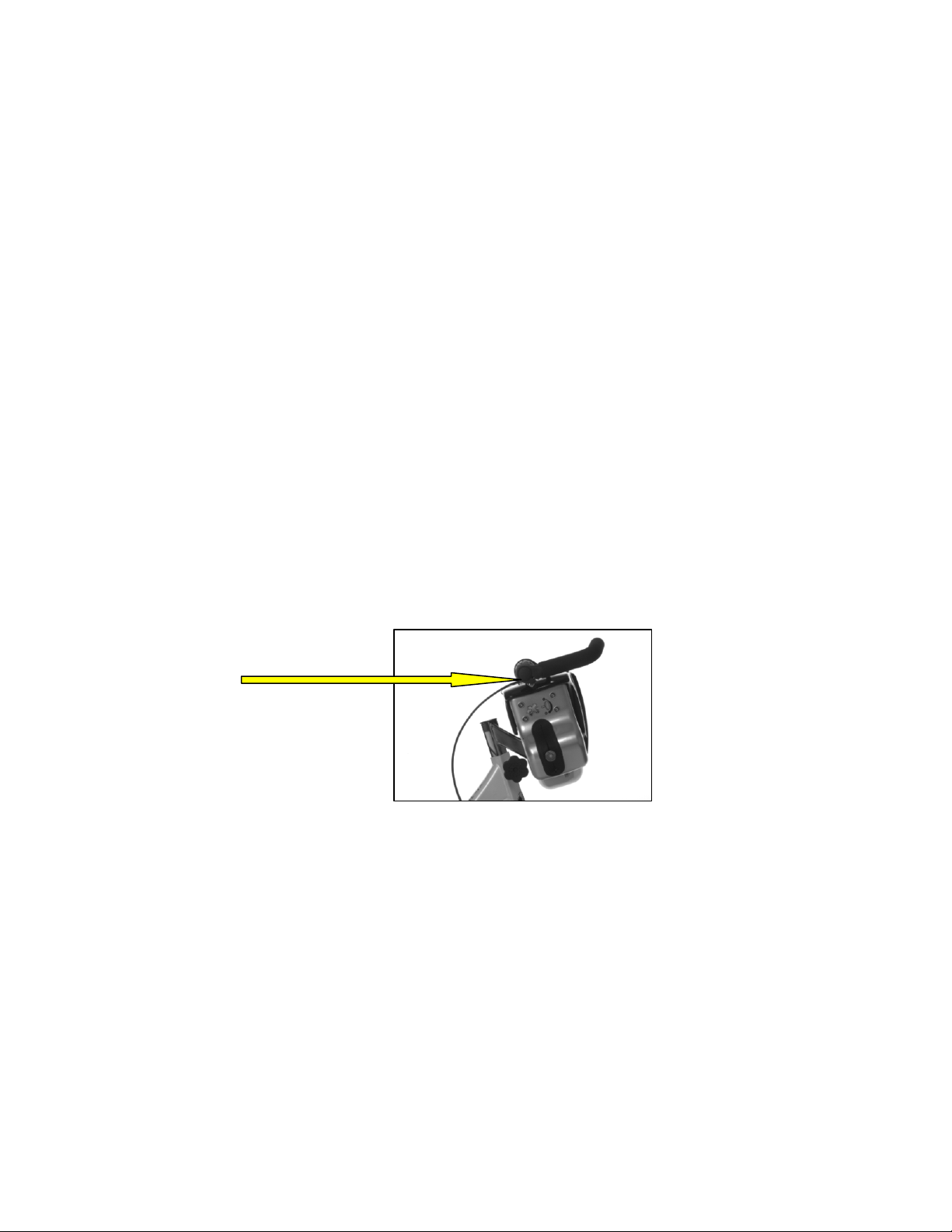
8. Fit the new bars ensuring that the orientation of the bar sweep is faced toward the rider as
shown. Replace the clamp cap and leave slightly loose until the Grip -shift™ has been
refitted and tightened.
9. The Grip-shift™ should be refitted to the right side of the bars ensuring that the cable exit
is facing back toward the user with about 5 to 10mm clearance between it and the top of
the cover.
Note the orientation
of the handlebar and
bar ends.
10. Tighten the 4 clamp bolts ensuring a) that the marked clamping area of the bars is central
within the clamp and b) the clamp is tightened evenly by all 4 bolts (This can be verified
by checking the width of the gap on both sides of the bars – it should be the same).
11. Using conventional hair spray, apply a film of spray to the inside of the grips before
fitting onto the ends of the handlebars. The hairspray dries rather quickly and it is
recommended to get the grips in place without delay ensuring to leave enough space at
the end of the bar for the bar ends. (The reason for the hair spray is that it acts briefly as a
lubricant but then dries to create a good grip with the bar).
12. Refit the bar-ends and fully tighten all points before riding the bike.
Replacing the Grip-shift™
1. For removal of the old Grip -shift™, follow procedures 3 to 7 within the section for
“Changing the handlebars” above. As the Grip -shift™ is removed from the right side
only, you do not nave to touch the left side of the handlebars.
18
Page 22
2. Using a 6mm hex key, loosen the bolt at the bottom of the V-Brake to release the
resistance cable.
3. Pull the resistance cable out of the assembly and all the way through the outer sleeve at
the top of the bike (You will have to cut off the protective nipp le at the end of the cable
using a snips in order pull it through the sleeve).
4. Ensure that you only use recommended replacement parts as other units may not perform
as intended and will affect the warranty on the bike.
5. From the new Grip -shift™, feed the cable down through the outer sleeve and in through
the V-Brake assembly. (Fit a new protective nipple to the end of the cable by squeezing
with pliers).
6. Place the handlebars back into the top clamp and tighten up by following procedures 8 to
12 within the section for “Replacing the Handlebars” above.
7. To set the resistance, turn the Grip-shift™ fully clockwise to the minimum resistance
setting. Using one hand, compress the 2 pads of the V-Brake to just make contact with
the flywheel. Pull the excess cable until it is tight in the cable clamp. Retighten the bolt to
secure the cable.
8. The resistance is set, when the minimum setting is free from contact with the flywheel
and position 2 just makes contact.
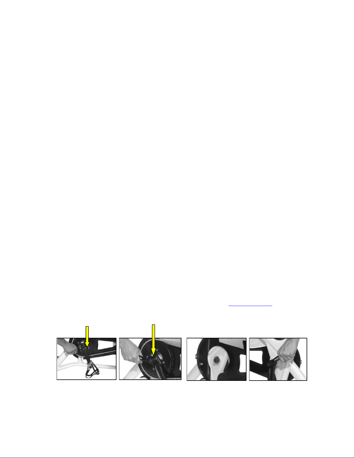
Removing Pedal Crank Arms
Left Crank Arm
1. Use an 8mm Hex key to remove the pedal crank bolt.
2. Thread a bicycle crank arm puller onto the crank arm shaft.
3. As you tighten the crank arm puller on the shaft, the crank arm will be extracted from the
crank arm shaft. Remove the crank arm from the frame.
4. Apply a thin coat of grease on the right bottom bracket shaft and install the right crank
arm on the bottom bracket spindle. Align the right crank arm 180º from the right crank
arm and push the crank arm onto the crank arm shaft.
5. Apply 1-2 drops of Loctite® 222 on the left crank arm bolt threads. Install the crank arm
bolt and tighten to secure the crank arm. Rotate the pedals a few revolutions and then
tighten the crank arm bolt again to ensure that the crank arm is tightened to a torque of
22ft/lb (30Nm)
NOTE: Inspect the Pedal crank arm bolts again after 30 hours (approx. one week). If
loose, remove the bolts; apply Loctite®222 and reinstall. Retighten the bolts to 22ft/lb
(30Nm). Monitor over the following week and if the proble m persists, contact your
service department (Details for your closest dealer found at www.trixter.net)
Crank Bolt Removal Crank Arm Puller
19
Page 23

Right Crank Arm
1. Follow procedures for “Removing the Chain Guard” above.
2. Use an 8mm Hex key to remove the pedal crank bolt.
3. Thread a bicycle crank arm puller onto the crank arm shaft.
4. As you tighten the crank arm puller on the shaft, the crank arm will be extracted from the
crank arm shaft. Remove the crank arm from the frame.
5. Apply a thin coat of grease on the right bottom bracket shaft and install the right crank
arm on the bottom bracket spindle. Align the right crank arm 180º from the left crank arm
and push the crank arm onto the crank arm shaft.
6. Apply 1-2 drops of Loctite® 222 on the right crank arm bolt threads. Install the crank
arm bolt and tighten to secure the crank arm. Rotate the pedals a few revolutions and then
tighten the crank arm bolt again to ensure that the crank arm is tightened to a torque of
22ft/lb (30Nm)
7. Refit the Chain guard by following procedures for “Removing the chain guard” above.
NOTE: Inspect the Pedal crank arm bolts again after 30 hours (approx. one week). If
loose, remove the bolts; apply Loctite®222 and reinstall. Retighten the bolts to 22ft/lb
(30Nm). Monitor over the following week and if the problem persists, contact your
service department (Details for your closest dealer found at www.trixter.net)
Tightening the Bottom Bracket Bearings
1. Follow procedures for “Removing the chain guard” above.
2. Then follow the procedures for removing the pedal crank arms above.
3. Loosen the locking cap on the left side of the bike using the locking cap removal tool.
4. Ensure that the right bearing cup is tight. If necessary, tighten with the bottom bearing
cup tool. Note: the right bearing cup is reverse threaded.
5. Check the left bearing cup. If the bearing cup is loose, tighten with your fingers. Then use
the bottom bracket tool to tighten the bearing cup by rotating the bottom bearing cup tool
an additional 10º clockwise.
6. Verify that the bottom bracket spindle is not loose by tugging on the spindle shaft.
7. Use the lock ring removal tool to tighten the lock ring. Note: Prevent the left bearing cup
from spinning by stabilizing it with the bottom bearing cup tool.
8. Apply a thin coat of grease on the left bottom bracket shaft and install the left crank arm
on the bottom bracket shaft. Apply 1-2 drops of Loctite® 222 on the left crank arm bolt
threads. Install the crank arm bolt and tighten to secure the crank arm. Rotate the pedals a
few revolutions and then tighten the crank arm bolt again to ensure that the crank arm is
tightened to a torque of 22ft/lb (30Nm)
9. Apply a thin coat of grease on the right bottom bracket shaft and install the right crank
arm on the bottom bracket spindle. Align the right crank arm 180º from the left crank arm
and push the crank arm onto the crank arm shaft. Apply 1-2 drops of Loctite® 222 on the
left crank arm bolt threads. Install the crank arm bolt and tighten to secure the crank arm.
Rotate the pedals a few revolutions and then tighten the crank arm bolt again to ensure
that the crank arm is tightened to a torque of 22ft/lb (30Nm)
10. Follow procedures for “Replacing the Chain” and complete the operation by adhering to
the section for “Removing the Chain Guard”
NOTE: Inspect the Pedal crank arm bolts again after 30 hours (approx. one week). If
loose, remove the bolts; apply Loctite®222 and reinstall. Retighten the bolts to 22ft/lb
(30Nm). Monitor over the following week and if the problem persists, contact your
service department (Details found at www.trixter.net for your closest dealer)
20
Page 24
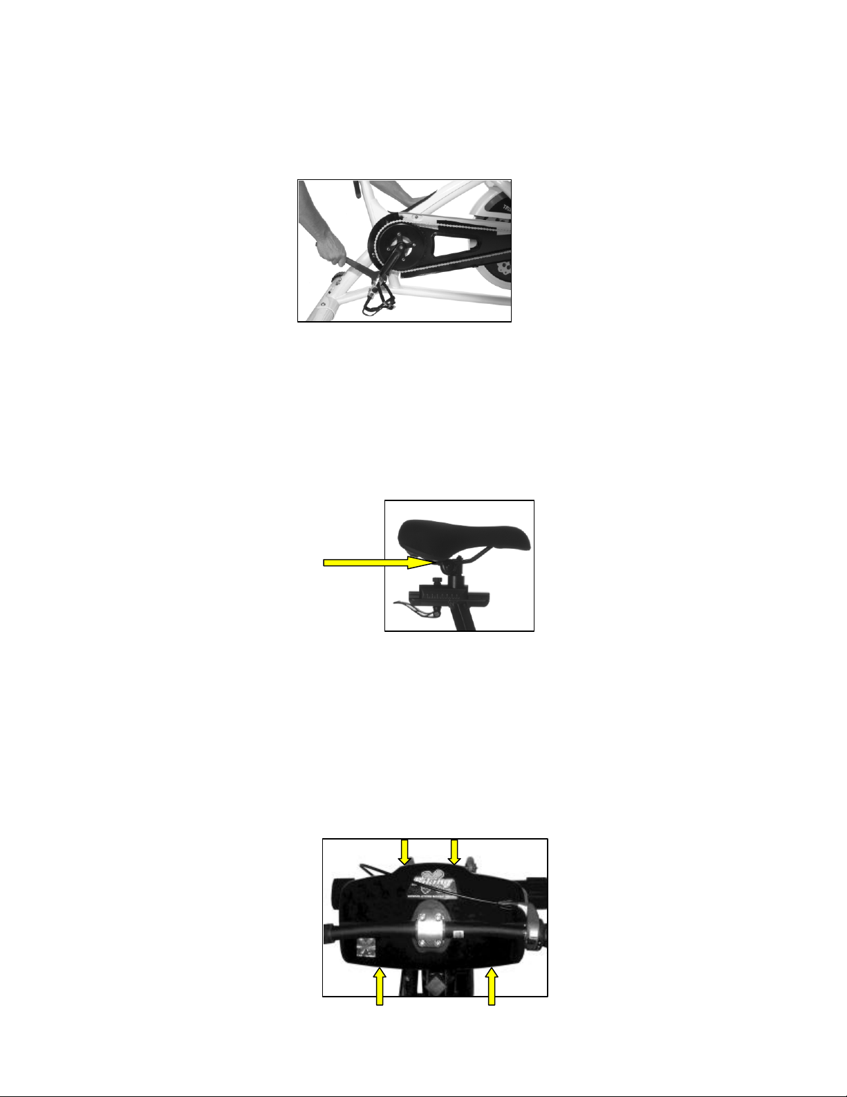
Removing Pedals
1. Block the crank arm from spinning, and use a bicycle pedal wrench (15mm) on the pedal
nut to remove the pedal from the crank arm.
2. Left Pedal: Turn the pedal nut clockwise and remove the pedal from the Pedal crank.
3. Right Pedal: Turn the pedal nut counter-clockwise and remove the pedal from the Pedal
crank.
4. Install the new pedals by lightly greasing the threads and reversing steps 1 to 3.
Replacing the Saddle (from the seat post)
1. Using a 6mm hex key, loosen the bolt to release the seat clamp.
Seat Clamp Bolt
2. Lift the seat off the seat post.
3. Position the new seat on the seat post, level and align the seat as required, and tighten the
clamp securely.
Removing the X-Bars covers
Top Cover
1. First remove the handlebar complete with bar-ends and Grip-shift™ from the top clamp
(see “replacing the handlebar” section above).
Front Bolts
21
Page 25
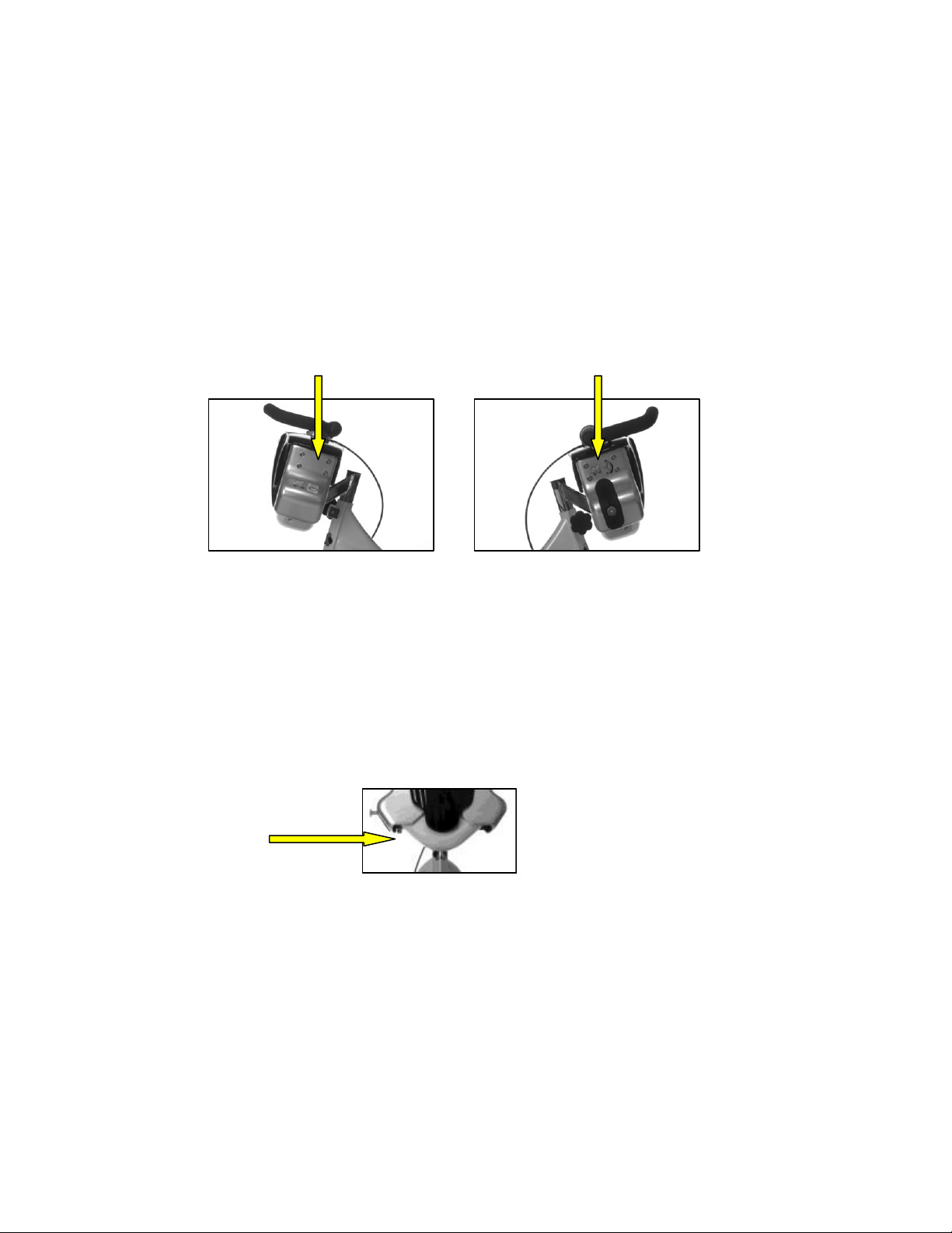
Rear Bolts
2. Undo the Top Covers – at the front and rear by using a 4mm extended hex key. Carefully
lift the top cover (front and rear) upwards over the top clamp.
3. To reassemble, carefully position the covers back onto the assembly by easing it
downwards over the top clamp until the holes are lined up on the internal assembly.
4. Thread all bolts before tightening any one to ensure that the holes are correctly lined up.
5. Take care to ensure that the seal is correctly secured into the groove on the top bar of the
assembly before fastening back onto the assembly.
Side Covers
1. Using a 4mm hex key, remove the 4 bolts holding the side co ver onto the assembly to
gain access.
Side Cover Bolts
2. When removing the cover from the right side, take care not to damage the brush seal
when removing over the damper adjuster.
3. When refitting, thread all 4 bolts before tightening any one to ensure that the holes are
correctly lined up.
Bottom Cover
1. Using a 4mm hex key, remove the 2 bolts holding the bottom cover onto the assembly to
gain access.
Bottom cover bolts
2. Drop the bottom cover downwards from the assembly.
3. Refitting is simply to locate the fixing holes and fit the bolts back in.
Replacing the Damper
1. For this section, only replace with Trixter recommended damper.
2. Remove all covers as directed in the “Removing the X-Bars Covers” section.
3. Using a 13mm wrench remove the nut from the fixed end of the damper.
4. Using 10mm and 13mm wrenches, undo the nut from the damper pin at the moving end
of the damper. Remove all components from damper pin noting their position for
reassembly.
5. Install the new damper and slide moving eye onto the slider pin. Thread the nut to hold in
place.
22
Page 26

6. Locate the fixed end of the damper into the bracket on the assembly and fit the nut.
Tighten securely.
7. Tighten the moving end securely.
8. Refit the covers as directed in the covers removal sectio n.
23
Page 27
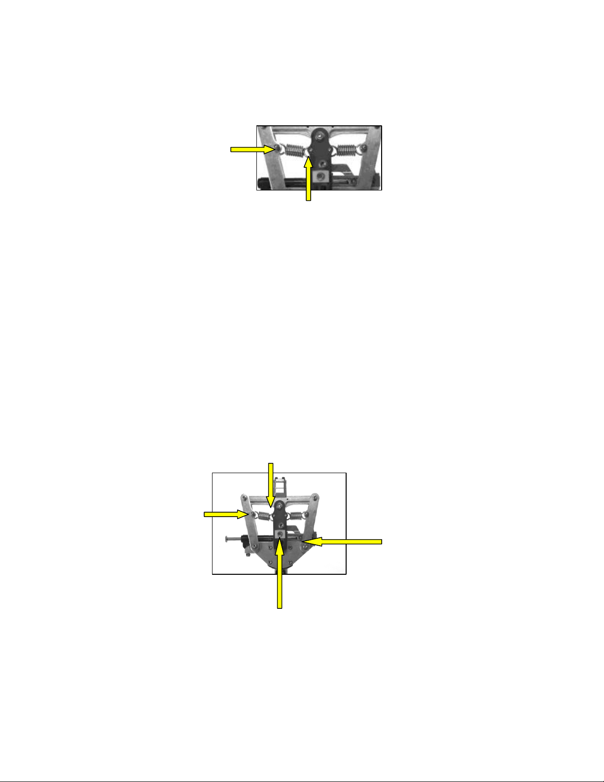
Replacing the “Return to Zero” Springs
1. Remove the top cover as directed in the covers removal section.
2. Using the spring fitting tool, insert into the inner spring loop (see diagram below) and
rotate the tool to free the loop from the spring pillar.
Outer Spring Loop
Inner Spring Loop
3. Take both old springs out before installing the new ones.
4. Install new spring by fitting the outer spring loop over the spring retaining pillar. Using
the spring fitting tool, insert into the inner spring loop and prise it over the outer inner
spring pillar.
5. Repeat for the second spring.
6. Apply a film of grease to the 4 loops and move the mechanism right and left a few times
to ensure that the grease has made contact all around the loop.
7. Refit the top cover as directed in the cover removal section.
Lubricating the Mechanism
1. Remove top covers as directed in the cover removal section.
2. Using a grease tube with a fine dispensing nozzle, point the nozzle into the following
areas;
Inner Spring Pillars
Outer Spring Pillars
Damper Slider
Centre Slider
a. The centre composite slider – apply some grease to each sliding edge on the sides
of the slider.
b. The damper sliders - apply some grease to the top and bottom surfaces of each of
the sliders.
24
Page 28

c. The spring pillars - apply some grease to each of the spring loops where they are
in contact with the spring pillars. Manoeuvre the mechanism left and right to
ensure that the grease has been applied all around the pillar.
3. Refit the covers as directed in the cover removal section.
25
Page 29
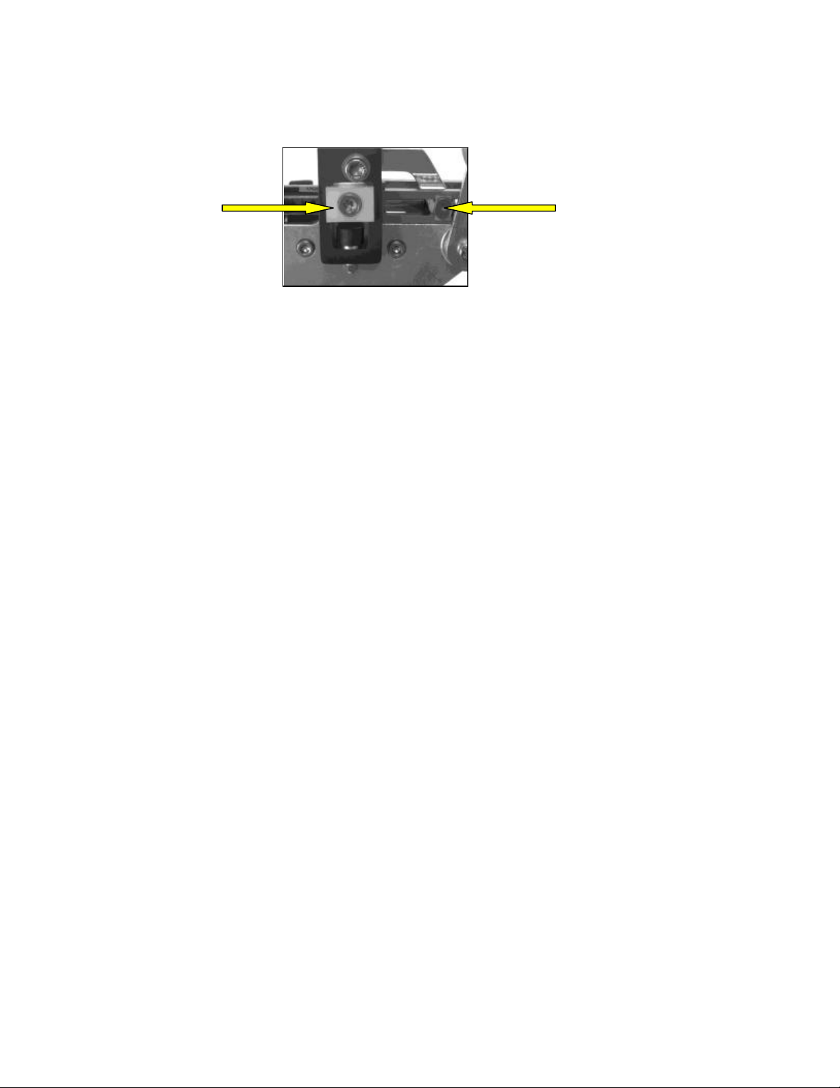
Replacing the Centre Slider
1. Remove the top and side covers as directed in the covers removal section.
2. Using an 8mm Hex head, undo the bolt retaining t his slider.
3. Remove the bolt taking care not to misplace the plastic washer behind the slider.
Centre Slider Damper Slider
4. Apply Loctite®222 to the bolt and fit through the new slider and reassemble. Tighten
securely.
5. Apply some grease to each sliding edge on the sides of the slider.
6. Refit the covers as directed in the cover removal section.
Replacing the Damper Slider
1. Remove the top and side covers as directed in the covers removal section.
2. Using 10mm and 13mm wrenches, undo the nut from the damper pin at the moving end
of the damper. Remove all components from damper pin noting their position for
reassembly.
3. Replace the 2 damper sliders with the new ones and reassemble in the same order as they
were disassembled. Tighten securely.
4. Apply some grease to each sliding edge on the sides of the slider.
5. Refit the covers as directed in the cover removal section.
26
Page 30
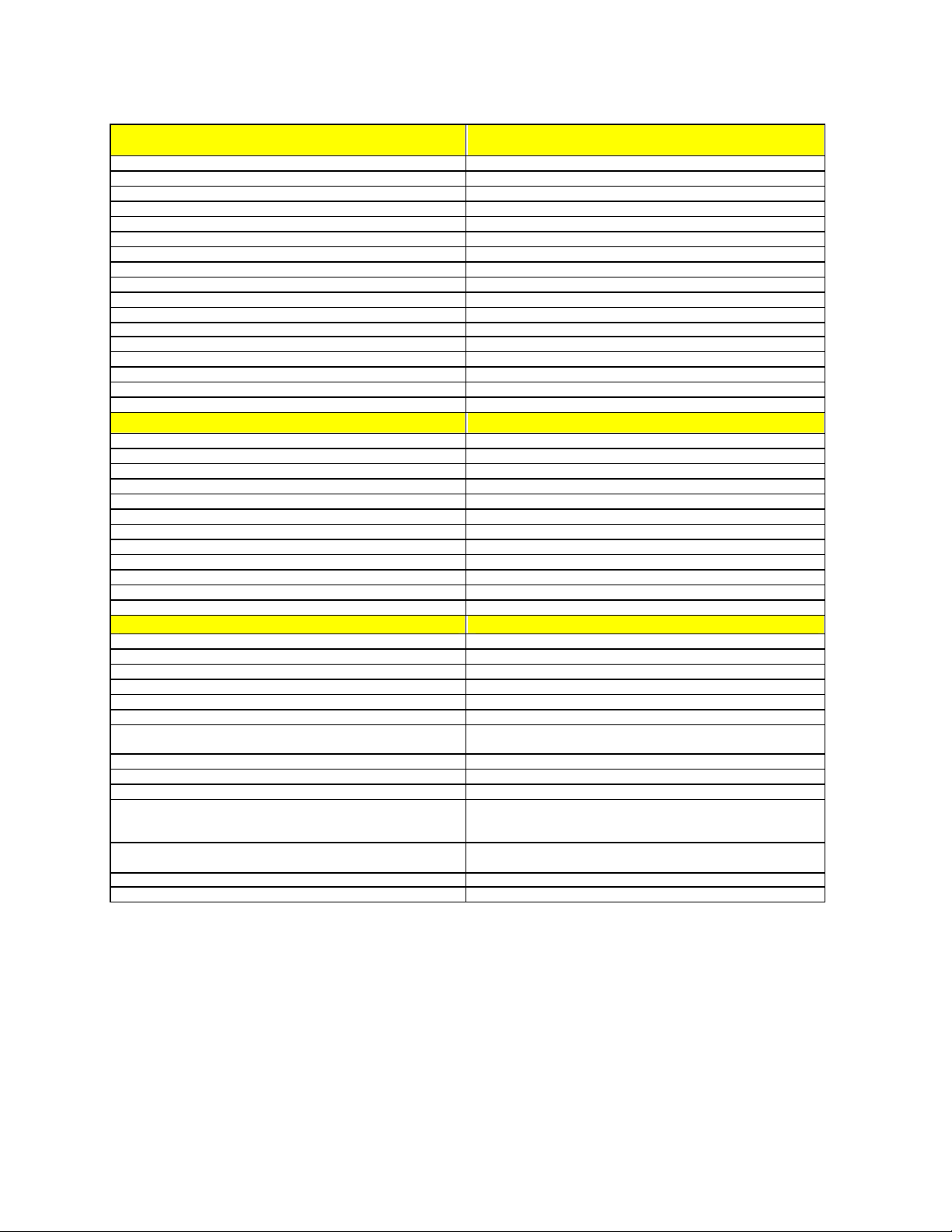
EQUIPMENT AND TECHNICAL INFORMATION
Please refer to Illustrations on Pages 30 to 32 for more information
X-Bike Frame Specifications
Frame Tubular Steel
Pedal drive system Freewheel drive pedals to Flywheel
Pedals Either Toe clip or SPD compatible clip less pedals
Flywheel 40 lb (18.2kg)
Flywheel resistance Multi-position SRAM Grip-shift™
Felt flywheel resistant pads 75mm x 25mm (3” x 1”) Felt Pads to provide smooth pedal action
Quick release height adjustment for handlebars 150mm (6”) vertical adjustment
Quick release saddle height adjustment 340mm (13.5") saddle height adjustment
Quick release saddle reach adjustment 75mm (3") saddle reach adjustment
Tilt Adjustable saddle Yes
Metallic and lacquer protected paint system Yes
Transport wheels on front base leg Yes
Protective plastic caps on base legs. Yes
Water bottle cage fittings Yes
Chain tension adjustment Yes
Non-slip rubber base for leveller feet Optional
Elbow pads and arm rests. Optional
X-Bars Specifications
Handlebar banking Angle to Bump Stops 12°
Handlebar banking Angle with stops compressed 14°
Maximum Horizontal Throw 102mm
Maximum Vertical Throw 60.8mm
Return to Zero Yes
RTZ spring resistance From 300N at centre to 775N at max extremes
X-Bar Damping resistance adjustability 10Kg-f to 50Kg -f
X-Bar Damping range 7 positions
Max allowable force up on handlebars 500N
Max allowable force down on handlebars 1000N
Max Force Fwd/Back on the handlebars 500N
Maximum torque about head tube 170 N-m
General
Nominal height to centre of handlebars 980mm
Distance from centre of handlebars to Seat Post 580mm nom. (+/- 100mm)
Distance from centre of handlebars to Head Tube 50mm nom.
Pitch of X-Bar movement to horizontal 72 Deg
Adaptor Bespoke to suit a range of exercise spinner bikes
Base Width 700mm wide base legs to provide excellent stability.
Mechanism Structure Die Cast Aluminium 356, machined aluminium and Hard Anodised
6061.
Bearings S45C and SCM430 Steel Chrome Plated
Bushings and Slider Materials Igus Iglidur G and MC901
Covers Injection Moulded ABS
Handlebars HANDLEBARS - 580mm to 680 max straight with 5 deg sweep
with wall thickness 3.2mm at centre. Material 2014 Aluminium -
Black anodise.
Bar Ends BAR ENDS - 28.6mm O/D as per SOS Boxer Design. Finish –
Black Anodised. Material 2014 Aluminium.
Hand Grips GRIPS - Length 11.5cm to 12cm. Colour Black. Finish ribbed
Fasteners Zinc & Clear Passivate
27
Page 31
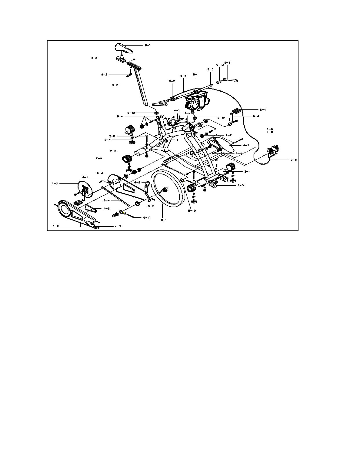
Exploded View & Parts Identification
1 FRAME 8-1 SEAT
2-1 FRONT BASE LEG 8-2 SEAT POST
2-2 REAR BASE LEG 8-3 SEAT QUICK RELEASE
2-3 BASE LEG CAP 8-4 HEIGHT ADJUSTER KNOB SET
2-4 LEVELLER FEET SET 8-5 SEAT POST STAND
2-5 TRANSPORT WHEEL 9-1 CLAMP BOLTS
2-6 BASE LEG BOLT SET 9-2 GRIPSHIFTER
4-1 KICK PLATE 9-3 HANDLEBAR
4-2 KICK PLATE COVER 9-4 BAR END
4-3 FENDER 9-5 CABLE ASSSEMBLY
4-4 FENDER BOLT SET 9-6 POWER ADJUSTER
4-5 INNER CHAIN GUARD 9-7 HEIGHT ADJUSTER KNOB SET
4-6 RUBBERSEAL 9-8 RESISTANCE SYSTEM
4-7 EX CHAIN GUARD WITH SEAL 9-9 RESISTANCE PAD
4-8 CHAIN GUARD BOLT SET 9-10 RIGHT CHAIN ADJUST
4-9 RUBBER GUARD 9-11 LEFT CHAIN ADJUST
5-1 FLYWHEEL 9-12 SQUARE RUBBER CAP
5-2 FREE WHEEL 9-13 HANDLEBAR GRIP
6-1 PADEL
6-2 CHAIN WHEEL
6-3 BOTTOM BRACKET AXLE
6-4 CHAIN
28
Page 32
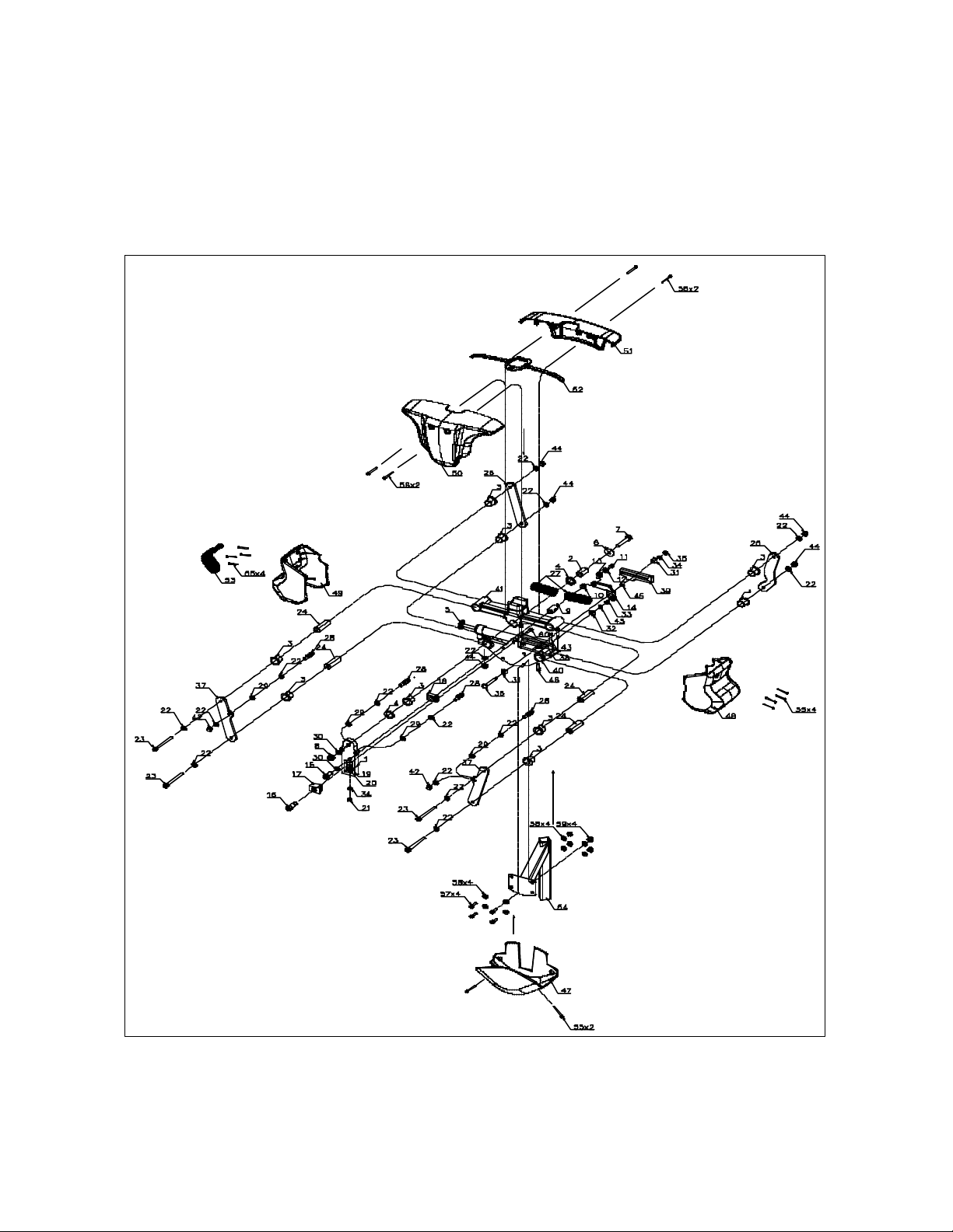
X -Bars Exploded View
29
Page 33
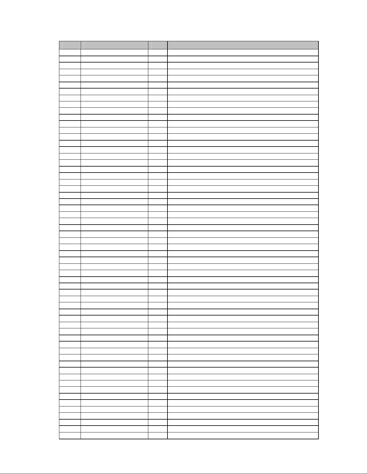
X -Bars Parts Identification Table
ID PART NUMBER QTY
1 1283-BP6300-001 1 BP63 147.2X46XT14 A6061-T6 ANOD
2 1282-AX1Y00-001 1 AX1Y D20X10.5X34.5L SCM430 CP
3 1282-FB01C0-001 9 FB01C 23X20 L21.5(GFM-2023-21)
4 1285-WS4000-001 2 WS40 D30X20.5X3 UPE
5 1281-ODM500-001 1 NHK ODM 500 DAMPER FOR TRIXTER
6 1285-WS40A0-001 1 WS40A D30X20.5XT2 SPCC CP
7 2110-BB04M1-001 1 BB04 M10X1.5X55 CRMO CP
8 212-4013C1 1 M10X1.5 T9.5 CP(NYLON NUT)
9 1282-AX1Z00-001 1 AX1Z D18X10 S45C CP
10 1282-FB2400-001 1 FB24 D12XD10XL9 (GFM1012-9)
11 211-4616C8 1 BB04AH M6X1.0X16 CP NYLOCK
12 2120-WASHER-009 1 6.2X18XT2 SPCC CP
13 1285-WS4100-001 1 WS41 D18X6.2X3 UPE
14 1286-JP3500-001 1 JP35 A6061-T6 HARD-ANOD.
15 2110-BB04M1-002 1 BB04 M10X1.5X20 CRMO CP W/NYLOCK
16 2110-BB04M1-005 1 BB04 M10X1.5X30/M5X20 CRMO CP W/NYLOCK
17 1283-BP6400-001 1 BP64 W25XH21 MC901
18 1285-WS4300-001 1 WS43 D24Xd12.5X7.5 UPE
19 1282-AX2C00-001 1 AX2C D20XM6XL34 SS41 CP/
20 212-1016C1 1 56A1 6.3X13.5X3.5 FLAT UCP
21 212-4002-1 1 M6 UCP
22 212-1004D7 15 M8 T1.5 FLAT OD16 STL
23 2110-BB04M8-002 4 BB04 M8X1.25X85 CRMO CP
24 1282-AX2B00-001 4 AX2B D20Xd8.1XL58.5 S15C CP
25 1286-JP4300-001 1 JP43 A6061-T6 SIL ANOD(X-BAR)
26 1286-JP3600-001 1 JP36 A6061-T6 SIL ANOD.
27 1281-SPRING-009 2 SPRING D25.4Xd3.66XL68 CP (X-BAR)
28 1282-AX2A00-001 4 AX2A D12XM8X36L S15C CP
29 212-1004E5 4 M8 SPRING WASHER CP
30 212-1007-4 2 M10XT1.2 UCP
31 1283-BP6500-001 2 BP65 W12XH14 MC901
32 1285-WS4400-001 1 WS44 D20Xd8.1X8 UPE
33 1282-FB2700-001 1 FB27 D10Xd8XL8 GSM0810-08
34 212-1058C1 2 6.3/13XT1.2 CP (M6)
35 212-4002D6 1 M6 CP T=6 (NYLON NUT)
36 1282-AX2D00-001 1 AX2D D8XL45.1 SCM430 CP
37 1286-JP3700-001 2 JP37 A6061-T6 ANOD.
38 1283-BP6600-001 1 BP66 110X24XT10 A7075-T6
39 1283-BP7100-001 1 BP71 103X35.5XT10 A7075-T6
40 1283-BP6700-001 1
41 1286-JP3800-001 1 JP38 A356
42 2124-NUTM80-001 2 M8X1.25 NYLON NUT
43 2110-BB04M6-002 3 BB04 M6X1.0X35 CP W/NYLOCK
44 212-4003D3 5 M8 CP T=8 (NYLON NUT)
45 2120-WASHER-016 2 8.1X15XT0.9 SPCC CP
46 211-4BB04620C5 1 BB04 M6X1.0X20 CRMO CP
47 1276-XBARCV-003 1 X-BAR COVER DOWN ABS P-YELLOW-012C
48 1276-XBARCV-001 1 X-BAR COVER LEFT ABS P-GREY6C
49 1276-XBARCV-002 1 X-BAR COVER RIGHT ABS P-GREY6C
50 1276-XBARCV-F01 1 X-BAR COVER FRONT ABS P-BLACK 3C2X
51 1276-XBARCV-R01 1 X-BAR COVER REAR ABS P-BLACK 3C2X
52 1275-XBARW2-001 1 XBARW2 RUBBER PAD (X-BAR)
53 1275-XBARW1-001 1 XBARW1 RIGHT PAD (X-BAR)
54 1330-XBARHS-001 1 XBARHS H250 EXT99.9 CRMO CP
55 2110-BB1D00-001 10 BB1D M4X0.7X10 STL W/WASHER (TWIST)
56 211-4512B5 4 CP041A M5X0.8X12 STL WO/NYLOCK #3 TOOLS
57 211-4820B3 4 BB04AH M8X1.25X20 STL WO/WS
58 2120-WASHER-017 8 M8 8.2X12XT1.2 STL
59 212-4003D3 4 M8 CP T=8 (NYLON NUT)
60 2115-BB05AH-009 1 BB05AH M5X0.8X13 STL NYLON W/D14 WASHER
BP67 A356 POL
PART DESCRIPTION
30
Page 34

X-Bike Indoor Performance Bike FEATURES
Structure
X-BIKE™ Indoor Performance Bike
o High strength attractive tubular and elliptical steel X-bike™ Frame to provide
o 170 mm forged aluminium alloy crank arms with ISIS spline bottom bracket
o 40lb (18.2kg) Balanced Cast Flywheel providing optimum pedalling inertia.
o Heavy gauge steel chain guard sufficiently rigid not to crack or bend.
o High strength elliptical tube 700mm wide base legs for total stability
o Stainless Steel hardware throughout mechanism to prevent corrosion or
o Maximum Dimensions (Not working): Lth 47.5 inches x Wth 28.5 inches x Hgt
o Maximum User Weight Capacity: 300 lbs
o Commercial Warranty: Frame-5 Years, Parts-1 Years, Labor-6 Months, Wear
Wheels
X-BARS™ Handlebar System
o The die cast aluminium X-Bars™ System is lightweight with high strength
o Authentic tamper proof “Trixter Enab led” identification holographic decal placed
o Laser etched chrome plated square X-Bars™ adaptor to provide total lock
o X-Bars™ Bearings and Pivots constructed from high wear resistant Chrome
o X-Bars™ Pivot Bushings and sliders constructed from maintenance free self
o 27” (680mm) straight 2014 aluminium handlebars to cater for wide reach upper
an incredibly solid X-Bike™, strong enough to handle riders 300lbs (135kg).
mount with 104/64, 4 bolt chain ring pattern for increased strength and reliability.
Crank arms are interchangeable with all popular top quality crank arms except
Shimano, so users can install their desired crank arm length.
freezing.
39 inches
Items-6 Months (Country Dependent). The following parts list includes all wear
parts that are protected under the warranty terms for a period of six-months past
the date of X-Bike Indoor Performance Bike purchase:
• Damper Unit • Height Adjustment Knobs
• Damper Access Seal • Levelling Feet
• Flywheel Resistance Pads • PU Transport
• Centre Slider Block • Handlebar and Bar End Grips
• ‘Return to Zero’ Springs • Resistance Cable (Twist Grip to V-Brake)
• ‘Return to Zero’ Spring Pillars
All other part and components are protected under the warranty for twelvemonths after date of purchase. The X-Bike Frame is protected under the
warranty for five -years after date purchase.
properties capable of withstanding 125lb -ft (170N-m) torque and 220lb (100kg)
vertical load at the end of the handlebars.
under the surface clear coat.
against turning slip.
Plated Hardened Steel S45C and SCM430 materials.
lubricating composites paired up with slide runners made from high wearing
hard anodised aluminium.
body workout.
31
Page 35

o 4-bolt clamp handlebar clamp to provide a very secure bar fitment.
o Boxer Bar ends
o Handlebar Grips – Hi grip rubber compound.
o Non-corrosive hardware fitted throughout mechanism to prevent corrosion.
Performance
o True Cycle Geometry provided by the unique trapezoidal movement about a
o Optimum low impact total body workout for the most efficient combined cross
o Adjustable Hydraulic X-Bars™ Damper resistance to enhance various levels of
o X-Bars™ ‘Return to Zero’ system providing up to 170lb (780N) pulling force in
o Boxer Bar Ends which provide alternative upper body muscle group workouts
o High inertia drive system comprised of the 40lb (18.2kg) flywheel and direct
o The transmission system is built to pro road bike standards. TH Power Pro 9900st
o 3” x 1” (75mm x 25mm) felt pads to provide smooth pedal action and evenly
o KMC S10 Stainless Steel chain (½ x 1/8” – 116 links) for low maintenance.
o Shimano SF-MX30 ½ x1/8, 16T freewheel and 52 tooth steel chain ring for
o VP D68 aluminium alloy two sided pedals with chrome molly axles allowing a
Adjustability
o Fully indexed Grip-Shift™ providing a very efficient and easy to control
o Fully adjustable X-Bars™ Damper Resistance System for upper body elements.
o A five -way, fully adjustable Rider Compartment accommodates users of nearly
o A self-aligning handlebar stem adjusts vertically up to 5” (130mm) with laser
o Quick release Saddle Reach adjustment up to 3.5” (90mm) via an extremely rigid
o Quick release Saddle Height adjustment laser etched “Indexed” seat positioning.
virtual cycling pivot point.
training to be found on an indoor cycle.
upper body exercise.
the mechanism to centralise the bars for regular spinning.
and also provide a wrist rest for added rider comfort.
drive gearing to simulate closely the feel of road riding. The sidewall resistance
surface of the flywheel is machined to a perfectly even finish. Each wheel is
finely balanced through a carefully programmed drilling operation to remove
small quantities of distributed weight. The flywheel assembly is completed by
fitting a high quality bearing.
Bottom Bracket with ISIS spline drive, hollow, chrome molly steel spindle and
sealed cartridge bearings. Standard 68mm bottom bracket width, 110 mm spindle
length. The ISIS spline crank arm mounting system is superior to square tapered
spindles because it is stronger, less likely to squeak or come lose and makes crank
arm removal and installation faster and easier.
distributed resistance.
added life.
choice of SPD clip -less or half-toe clip.
adjustment to the flywheel resistance system for lower body elements.
any size. Easily accessible and large one -hand quick release levers to make most
the quick and easy adjustments.
etched reference numbers on the handlebar stem aid when resetting your position.
extruded aluminium track and guide. Laser etched reference numbers on the
sliding saddle base help you set your favorite position.
An extra long, self-aligning seat post adjusts 15.75” (400 mm) to accommodate
32
Page 36

riders from below 5’ (1.5m) to 7’ (2.15M) tall. Laser etched reference marks on
the seat post make resetting a favorite position easy.
o Saddle Tilt of 1.5” (38mm) fore/aft adjustment.
o Four leveller feet can be adjusted to compensate for irregular floor surfaces.
o Easily accessible Chain tension adjusting bolts to allow simple chain adjustment.
Safety
o The X-Bars™ Handlebar System mechanism is enclosed to minimize the
possibility of contact with moving parts.
o The Grip-Shift™ position on the handlebars allow the rider to maintain hand s and
grip in their assumed riding position for comfort, safety and non-interruption to
the exercise routine.
o X-Bars™ System buffered end stop within the mechanism to provide smooth
transition between left and right body movement ensuring no body injury.
o Hi -grip compound bar end covers to provide excellent hand grips at the
outermost point of the handlebars.
o 28” (700mm) wide base feet for added stability and safety have been fully tilt-
table tested.
o Non-slip rubber cushions under the leveller feet to ensure no bike movement,
even when bike is vigorously worked.
o Freewheel mechanism as per standard bicycle ensuring safer cycling with the
absence of the inertia of a fixed flywheel.
o Double-sided pedals giving the 2 safe options of either toe clips or shoe clips.
Style & Comfort
o Highly attractive and futuristic curved monocoque X-Bike™ Frame built from
round and elliptical tubular steel.
o 3 Tone, corrosion-resistant, zinc plated and powder coated metallic paint system
with added protective and cosmetic enhancing clear lacquer coating system for
unrivalled presentation and corrosion resistance.
o Integrated moving covers system displaying working geometry.
o Stylish front fender enhancing X-Bike’s™ look and keeping the corporate
curved image throughout.
o Contoured highly cushioned seat – male and female for maximum comfort
o Rider controls are all conveniently located, simple to use and allow for
maximum rider comfort and non-interrupted X-Biking™ Ride.
Protection
o Paint system – as above with the added benefit of accepting all conventional
cleaning materials.
o Sweat protection – All covers and general X-Bike features are specifically
designed to channel sweat away from sensitive areas.
o Rubber seals provided at all points directly within the sweat zone ensuring no
sweat ingress to the working mechanisms.
o Easily replaceable plastic covers on the handlebars and frame to protect your
investment.
o Plastic kick-plate cover to protect the frame paintwork when mounting and
dismounting the X-Bike™ Indoor Cycle.
o Front flywheel fender to channel sweat away from sensitive areas including
moving parts and V-Brake system.
33
Page 37

o V-Brake mechanism is fitted below the flywheel, well out of sweat zone for
increased longevity and ease of maintenance.
o Chain guard to protect the moving drive parts.
o Full seam rubber seals around the chain guard to keep corrosive sweat away
from moving parts inside.
o Protective plastic caps on 4 corners of base legs.
Service and Maintenance
o Quick release covers for accessing dampers and springs when necessary.
o Chain cover with oiling point – exceptional ease of maintenance
o Easily accessible chain tensioning points .
Mobility & Storage
o Two Large, 3”(75mm) diameter polyurethane transport wheels to absorb uneven
floor surfaces and also to assist when moving X-Bike™ through door thresholds.
Polyurethane won’t scuff or mark floors either.
Additional Features & Options
o Easily accessible water bottle holder
o New integrated water bottle holder holds 1 litre bottles of any shape
o SPD Compatibility
o Elbow pads and arm rests.
34
Page 38
THANK YOU FOR PURCHASING AN X-BIKE INDOOR PERFORMANCE BIKE
PLEASE TAKE A FEW MORE
MINUTES TO READ OUR
WARRANTY POLICY (PAGE 39), RECORD AND RETAIN YOUR BIKE DATA (PAGE 40), AND
COMPLETE THE WARRANTY REGISTRATION CARD (PAGE 41). THE CA RD MUST BE RETURNED
TO YOUR NEAREST TRIXTER ENABLED HEADQUARTERS OFFICE WITHIN 14 DAYS OF
PURCHASE.
X-BIKE INDOOR PERFORMANCE BIKE WARRANTY CARD
(COPY FOR THE BUYER)
Frame Serial Number: ______________________________
Date Purchased: _________________ _____________
Bike Colour: ______________________________
Name of Dealer: ______________________________
X-BIKE INDOOR PERFORMANCE BIKE 6-MONTH WEAR PARTS
The following parts list includes all wear parts that are protected under the warranty terms for a period of six -months
past the date of X-Bike Indoor Performance Bike purchase
• Damper Unit • Height Adjustment Knobs
• Damper Access Seal • Levelling Feet
• Flywheel Resistance Pads • PU Transport Wheels
• Centre Slider Block • Handlebar and Bar End Grips
• ‘Return to Zero’ Springs • Resistance Cable (Twist Grip to V-Brake)
• ‘Return to Zero’ Spring Pillars
All other part and components are protected under the warranty for twelve-months after date of X-Bike Indoor
Performance Bike purchase.
The X-Bike Frame is protected under the warranty for five-years after date of X-Bike Indoor Performance Bike
purchase.
35
Page 39
LIMITED WARRANTY
Trixter North America, Inc. and Trixter Europe Limited (“Trixter”) warrant the frame of each new indoor cycle to be free from defects in material
and workmanship for a period of five years from the original date of purchase, as long as the original purchaser owns the cycle. All wear parts
are warranted to be free from defects in material and workmanship for the original owner for a period of six months from the original date of
purchase. The Wear Parts are listed in the User’s Manual and are available in advance on request. Reasonable wear and tear of the equipment is
specifically excluded from any manufacturers warranty obligations. All other original components and all Trixter brand repair parts, replacement
parts and accessories, except wear parts, are warranted to be free from defect in material or workmanship for a period of one year from the
original date of purchase.
For a period of six months from the original date of purchase, as long as the original purchaser owns the cycle, Trixter will cover the labor cost of
the warranty repair procedure. The limit of this element of warranty is covered by the indi vidual procedure for any repair, which includes the
limit on repair times based on the times taken by an experienced service engineer with the proper tools and training.
All potential warranty claims must be approved in advance of any work being carried out. Any claim for work already carried out without the
appropriate advance approval will be automatically rejected.
TRIXTER MAKES NO OTHER WARRANTIES, EXPRESS OR IMPLIED. ALL IMPLIED WARRANTIES, INCLUDING THE
WARRANTIES OF MERCHANTABILITY AND FITNESS FOR A PARTICULAR PURPOSE, ARE LIMITED IN DURATION TO THAT
OF THE EXPRESS WARRANTIES STATED ABOVE.
Some states do not allow limitation on how long an implied warranty lasts, so the above limitation may not apply to you.
Unless otherwise provided, the sole remedy under the above warranty or any implied warranty is limited to the replacement of defective parts with
those of equal or greater value at the sole discretion of Trixter.
IN NO EVENT SHALL TRIXTER BE RESPONSIBLE FOR INCIDENTAL OR CONSEQUENTIAL DAMAGES, WHETHER BASED ON
CONTRACT, WARRANTY, NEGLIGENCE, PRODUCT LIABILITY, OR ANY OTHER THEORY, INCLUDING, WITHOUT
LIMITATION, PERSONAL INJURY DAMAGES, PROPERTY DAMAGE, OR ECONOMIC LOSSES.
THE ABOVE WARRANTY, OR ANY IMPLIED WARRANTY, DOES NOT COVER NORMAL WEAR AND TEAR, AND ALL
WARRANTIES ARE VOID IF THE INDOOR CYCLING EQUIPMENT IS USED FOR OTHER THAN NORMAL ACTIVITIES
INCLUDING BUT NOT LIMITED TO FAILURE TO FOLLOW THE USER’S MANUAL, FAILURE TO FOLLOW THE MAINTENANCE
INSTRUCTIONS IN THE USER’S MANUAL, USE UNSUPERVISED BY AN AUTHORISED X-BIKING™ INSTRUCTOR OR THE USE
OF NON -GENUINE TRIXTER SPARE PARTS.
Some states do not allow the exclusion or limitation of consequential damages, so the above limitation or exclusion may not apply to you. This
warranty gives you specific legal rights, and you may also have other rights, which vary from state to state .
As soon as you experience any problems, note the serial number of the bike, locate your purchase receipt or other proof of date of purchase and your
portion of the Warranty Registration Card and contact your Vendor or Distributor.
Locate your purchase receipt or other proof of date of purchase, and then contact the Warranty/Service Department at:
Trixter Europe Ltd (UK) Trixter North America, Inc
Trixter House 654 Bair Island Rd
London Road Suite 309
Stroud Redwood City
Gloucestershire CA 94063
United Kingdom USA
Tel : +44-1453-840400 Tel : +1 -650-367-7525
Fax : +44-1453-840444 Fax : +1-650-367-9940
Email : [email protected] Email : [email protected]
For up to date information on your distribution network, please visit www.trixter.net.
LIMITED REMEDY
EXCLUSIONS
WHAT YOU SHOULD DO
Or
36
Page 40
WARRANTY REGISTRATION CARD
Thank you for purchasing this X-Bike Indoor Performance Bike. The Owners’ Manual contains important
information for proper riding and maintenance of the bike. Before riding, you should read the manual and request
that all users read the manual to ensure that the bike is set up and used correctly. You should pay particular attention
to the SAFETY INFORMATION on pages 4 and 5 of the Owners Manual to ensure that you or any user are in a
healthy physical condition to ride the bike and that the bike is set up correctly for individual use. If you do not fully
understand its operation, please contact your dealer. (See www.trixter.net )
Frame Serial Number: _________________________ Date Purchased: ____________________________
Bike Colour: ________________________________ Dealer Name: ____________________________
Owner’s Name: ______________________________ Email Address:_______________________
Street Address: ______________________________
______________________________
City: _____________________________________ Country:_______________________________
Please return this warranty card to your distributor within 14 days from the date of purchase, which includes the
following acknowledgement:
I have read the Owner’s Manual. I understand the SAFETY INFORMATION contained in it and that I must post a
copy of the X-Biking Safety Notice prominently in the place where the bikes are used. I have read and understand
the maintenance procedures set out in the Owner’s Manual, that are required to keep the X-Bike Performance
Bike in a safe operating condition and I understand that the X-Bike Limited Warranty is conditional on such
maintenance being performed.
Signature:______________________________________ Date : ____/_____/_____
On behalf of the buyer dd — mm — yy
From time to time we may wish to use the above information for further mailing or other commercial purposes. If
you do not wish your details to be used, please tick the box.
To validate the warranty provisions regarding your X-Bike Indoor Performance Bike, you MUST fill in and return
this Warranty Card to your nearest Trixter office within 14 days of purchase:
Trixter Europe Ltd (UK) Trixter North America, Inc
Trixter House, 654 Bair Island Rd
London Road Suite 309
Stroud Redwood City
Gloucestershire GL5 2AY CA 94063
United Kingdom USA
37
Page 41

Dear new X-Bike™
Performance Indoor Bike Owner:
This is the backside of the Warranty Registration Card.
If you have not completed the Warranty Card –
Please DO SO NOW and MAIL IT IMMEDIATELY!
THANK YOU.
38
Page 42

INDEX
Adjustment
10
Assembling the X-Bike Indoor Performance Bike 7
Basic Exercise Instructions 12
Bottom Bracket Bearings 24
Carton Contents 6
Centre slider replacement 28
Chain Guards 20
Chain lubrication 16
Chain replacement 21
Chain Tension Adjustment 16
Cleaning the X-Bike 15
Contents 3
Covers removal 26
Crank arm removal 23
Daily Maintenance 15
Damper performance 17
Damper replacement 26
Damper slider replacement 28
Dismounting the X-Bike 13
Exercise Guidelines 12
Exploded Views 30
Flywheel 20
Flywheel Resistance adjustment 15
Grip-shift replacement 22
Handlebar replacement 21
Pump ing 12
Looseness 18
Maintenance 14
Mechanism lubrication 15
Monthly Maintenance 16
Mounting the X-Bike 13
Pedal Strap Adjustment 11
Pedalling 12
Pedalling resistance 10
Pedals replacement 24
Preventative maintenance 15
Product Features 34
Resistance Pads 19
Return to zero performance 17
Saddle replacement 25
Seat Adjustment 9
Setting up 7
Slider wear 18
Spare Parts 30/32
Springs replacement 27
Technical Specifications 29
Tools 14
Using the X-Bike 12
Weekly Maintenance 15
X-Bar resistance 13
39
Page 43
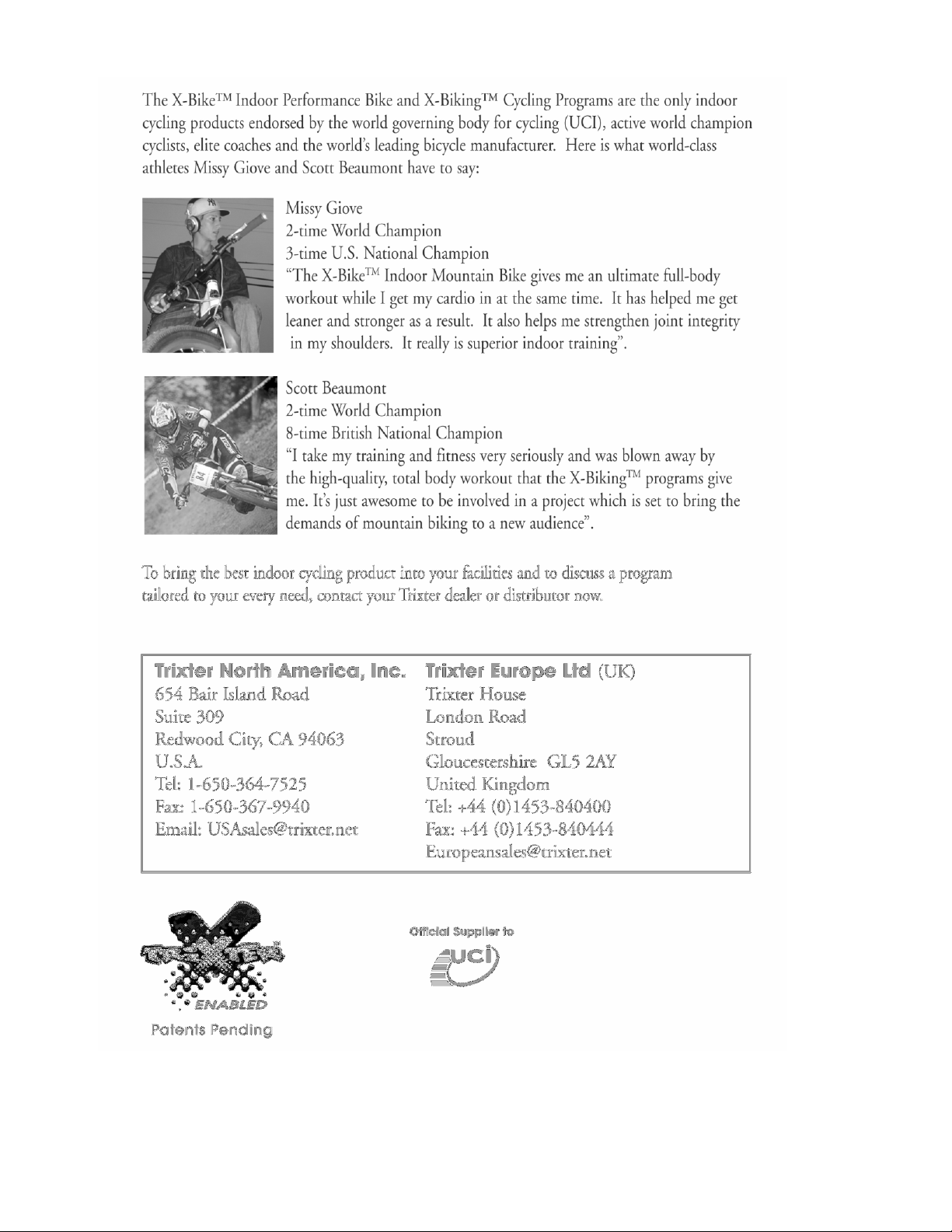
40
 Loading...