

Page 1

Modell der
BR 212 / V 100
I
I
I
I
I
I
I
I
I
I
I
I
I
I
I
I
I
I
I
I
I
I
I
I
I
I
I
I
I
I
I
I
I
I
I
I
I
I
I
I
Page 2

2
Informationen zum Vorbild
Im Jahre 1958 begann die Deutsche Bundesbahn mit
der Indienststellung der dieselhydraulischen Mehrzwecklokomotiven der Baureihe V 100. Sie sollte u.a.
die Nebenbahndampfloks ablösen und den Perso
nenzugbetrieb auf Nebenbahnen rentabel machen.
Auch schwere Güterzüge konnten mit bis zu 60 km/h
befördert werden.
Die Lokomotiven wurden mit Motoren von Maybach,
MAN oder Daimler-Benz ausgestattet. Da jedoch immer
das Getriebe von Voith verwendet wurde, konnten
die Motoren gegenseitig ausgetauscht werden. Ab
1962 wurden die Lokomotiven mit stärkeren Motoren
ausgeliefert und gleichzeitig als V 100.20 bezeichnet.
Bei der Umstellung auf Computer-Nummern wurden
die Maschinen dann als BR 211 (V100.10) und BR 212
(V100.20) eingereiht. Einige mit einer besonderen
hydrodynamischen Bremse für Steilstreckenbetrieb
ausgerüstete Maschinen wurden als BR 213 eingereiht.
Achsanordnung B‘B‘
Länge ü. Puffer 12 100 mm
Höchstgeschwindigkeit 100 km/h
Dienstmasse 62 t
Nennleistung 993kW (1350 PS)
Baujahr ab 1958
Wheel arrangement B-B
Length over buffers
12,100 mm / 39 ft. 8-3/8 in
Maximum speed 100 km/h / 63 mph
Service weight 62 metric tons
Nominal performance 993 kilowatts / 1350 hp
Built starting in 1958
Information about the prototype
In 1958, the German Federal Railroad began to place
the class V 100 general-purpose diesel hydraulic locomotives into service. It was intended to replace branch
line steam locomotives among other things and to
make passenger train operations profitable on branch
lines. It could even pull heavy freight trains at speeds
up to 60 km/h / 38 mph.
These locomotives were equipped with motors from
Maybach, MAN, or Daimler-Benz. Since only Voith
transmissions were used, the motors were interchange
able. From 1962 on the locomotives were delivered with
more powerful motors and were simultaneously desig
nated as the V 100.20. In the conversion to computer
numbering, these locomotives were then designated as
the class 211 (V100.10) and class 212 (V100.20). Several units equipped with special hydrodynamic brakes
for steep grades were designated as the class 213.
Page 3

3
Disposition d‘essieux B‘B‘
Longueur hors tampons 12 100 mm
Vitesse maximale 100 km/h
Poids en ordre de marche 62 t
Puissance nominale 993 kW (1350 CV)
Année de construction 1958
Asopstelling B‘B‘
Lengte o. buffers 12 100 mm
Maximumsnelheid 100 km/h
Dienstmassa 62 t
Nominaal vermogen 993 kW (1350 pk)
Bouwjaar vanaf 1958
Informations concernant le modèle réel
En 1958, la Deutsche Bundesbahn commença à mettre
en service les locomotives dieselshydrauliques polyvalentes de la série V 100. Celles-ci étaient destinées
notamment à remplacer les locomotives à vapeur sur
les lignes secondaires et rendre rentables les trains de
voyageurs sur ces lignes. Elles pouvaient également
remorquer de lourds trains de marchandises à une
vitesse maximale de 60 km/h.
Les locomotives étaient équipées de moteurs pro
venant des firmes Maybach, MAN et Daimler-Benz.
Compte tenu de l‘utilisation permanente de la transmission Voith, les moteurs pouvaient être mutuelle
ment échangés. A partir de 1962, les machines furent
équipées de moteurs plus puissants et par conséquent
numérotées dans la série V 100.20. Lors de l‘infor
matisation unifiée de la numérotation des véhicules
ferroviaires, ces locomotives furent désignées BR 211
(V100.10) et BR 212 (V100.20). Quelques-unes dotées
du singulier freinage hydrodynamique furent numéro
-
tées dans la série 213.
Informatie over het voorbeeld
In het jaar 1958 begon de Deutsche Bundesbahn met
de indienststelling van de dieselhydraulische multifunctionele locomotieven van de serie V 100. Die moest
o.a. de stoomlocs voor de zijlijnen aflossen en het
reizigerstreinbedrijf op zijlijnen rendabel maken. Ook
zware goederentreinen konden met maximaal 60 km/h
gereden worden.
De locomotieven worden met motoren van Maybach,
MAN of Daimler-Benz uitgevoerd. Omdat echter steeds
de overbrenging van Voith gebruikt werd, konden de
motoren onderling uitgewisseld worden. Vanaf 1962
werden de locomotieven met sterkere motoren geleverd
en tegelijk als V100.20 aangeduid. Bij de omschakeling
op computernummers werden de machines vervolgens
als BR 211 (V100.10) en BR 212 (V100.20) opgenomen.
Enkele met een bijzondere hydrodynamische rem voor
steile trajecten uitgeruste machines werden als BR 213
ingedeeld.
Page 4

4
Funktionen
• Dieses T
rix
-Modell ist entsprechend den gesetzli-
chen Vorschriften voll funk- und fernsehentstört
• Zum Schutz des Modells ist eine elektronische Über
-
lastsicherung eingebaut.
•
Dreilicht -Spitzensignal mit der Fahrtrichtung wechselnd.
• Eingebaute Elektronik zum wahlweisen Betrieb mit
konventionellem Gleichstrom-Fahrgerät, Trix Selec
-
trix oder Digitalsystemen nach NMRA-Norm (DCC).
• Die Betriebsart wird automatisch erkannt.
• Analog 14 Volt =, digital 22 Volt ~.
Functions
• This T
rix
model complies with the regulations concerning suppression of interference with radio and
television reception.
• An electronic overload protection is built to protect
the model.
• Triple headlights that change over with the direction
of travel.
• Built-in electronic circuit for oberation with an
conventional DC power pack, Trix Selectrix or NMRA
DCC digital.
• The mode of operation is automaticaly recognized.
• Analog 14 volts DC, digital 22 volts AC.
Fonctionnement
• Ce modèle T
rix
protégé contre l‘émission de
parasites radio et de télévision conformément aux
prescriptions légales.
• Une sécurité électronique protège le modèle contre
toute surcharge éventuelle.
• Feux triples avec alternance selon sens de marche.
• Electronique intégrée pour exploitation au choix avec
transformateur-régulateur conventionnel délivrant du
courant continu, avec Selectrix ou avec des sastèmes
de vonduite digitale conformes aux normes NMRA.
• Le mode d‘exploitation est automatiquement détecté.
• Analogique 14 volts =, digital 22 volts ~.
Functies
• Dit T
rix
-model is, volgens de geldende voorschriften,
geheel radio- en televisie-ontstoort.
• Voor de beveiliging van het model is een elektroni
-
sche overbelastingsbeveiliging ingebouwd.
• Drievoudige frontverlichting wisselend met de
rijrichting.
• Ingebouwde elektronica die het mogelijk maakt om
naar keuze met, een conventionele gelijkstromrij
regelaar, Trix Selectrix of digitaalsysteem volgens
NMRA-norm te rijden.
•
Het system (bedrijfsmodus) word automatisch herkend.
• Analog 14 Volt =, digital 22 Volt ~.
Page 5

5
Schmierung nach etwa 50 Betriebsstunden
Lubricate after about 50 hours of operation
Graissage environ toutes les 50 heures de fonctionnement
Smeren na ongeveer 50 bedrijfsuren
Reinigung der Lokräder
Cleaning the locomotive wheels
Nettoyage des roues de locomotive
Reiniging van de wielen van de loc
66625 66626
O
I
L
66623
MINITRIX
I
I
I
I
I
I
I
I
I
I
I
I
I
I
I
I
I
I
I
I
I
I
I
I
I
I
I
I
I
I
I
I
I
I
I
I
I
I
I
I
Page 6
6
a
a
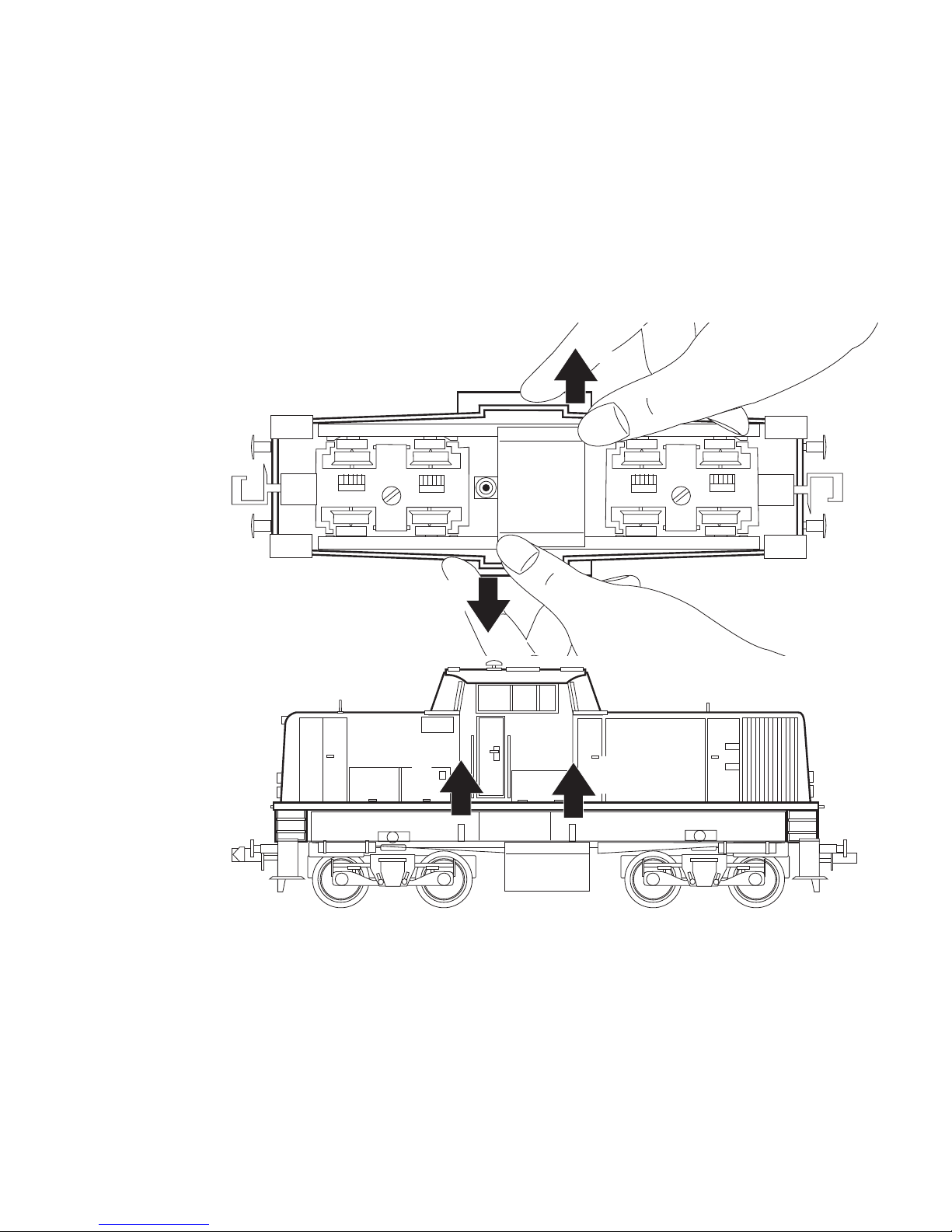
Lokgehäuse abnehmen
Removing the locomotive body
Enlever la caisse de locomotive
Loc-kap verwijderen
I
I
I
I
I
I
I
I
I
I
I
I
I
I
I
I
I
I
I
I
I
I
I
I
I
I
I
I
I
I
I
I
I
I
I
I
I
I
I
I
b
b
Page 7
7
I
I
I
I
I
I
I
I
I
I
I
I
I
I
I
I
I
I
I
I
I
I
I
I
I
I
I
I
I
I
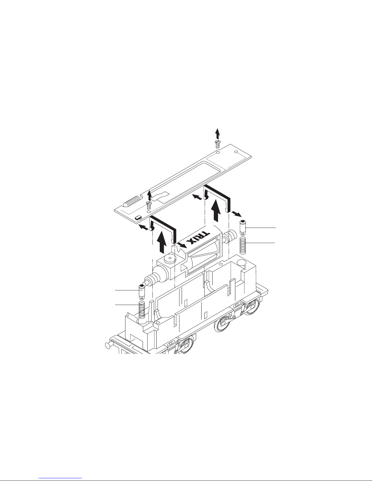
15 0250 00
15 0554 00
15 0250 00
15 0554 00
a
a
b
c
c
d
d
b
Lampen auswechseln (a + b)
Replacement of bulbs (a + b)
Changer les ampoules (a + b)
Verwisselen van lampjes (a + b)
Motor ausbauen (a + c + d)
Removing the motor (a + c +d)
Enlever le moteur (a + c + d)
Motor uitbouwen (a + c + d)
Page 8

8
• Der volle Funktionsumfang des Decoders kann nur in
Verbindung mit Trix-Selectrix-Steuergeräten garan
-
tiert werden.
• Nicht für Fahrgeräte mit Impulsbreitensteuerung.
• Nicht für Dauerzugbeleuchtung auf Analog-Anlagen.
• Nicht für Trix-ems.
• Die Lok darf nicht mit mehr als einer Leistungsquelle
gleichzeitig verbunden werden.
• Die Lok darf nur mit einem dafür bestimmten Be
-
triebssystem eingesetzt werden.
• Beachten Sie unbedingt die Sicherheitshinweise in
der Gebrauchsanleitung zu Ihrem Betriebssystem.
Jegliche Garantie-, Gewährleistungs- und Schadenersatzansprüche sind ausgeschlossen, wenn in Trix- Produkten nicht von Trix
freigegebene Fremdteile eingebaut werden und/oder Trix- Pro
dukte umgebaut werden und die eingebauten Fremdteile bzw.
der Umbau für sodann auftretene Mängel und/oder Schäden
ursächlich war.
Die Darlegungs- und Beweislast dafür, dass der Einbau von
Fremdteilen oder der Umbau in bzw. von Trix Produkten für
aufgetretene Mängel und/oder Schäden nicht ursächlich war,
trägt die für den Ein- und/oder Umbau verantwortliche Person
und/oder Firma bzw. der Kunde.
Hinweis für den Selectrixbetrieb:
Wird ein eingeschalteter Bremsabschnitt entgegen der
Fahrtrichtung des Bremsabschnittes befahren, geht das
Fahrtlicht im Bremsabschnitt aus. Nach dem Bremsab
-
schnitt schaltet sich das Licht wieder zu.
Hinweise zum Digitalbetrieb:
• Die genaue Vorgehensweise zum Einstellen der
diversen Parameter entnehmen Sie bitte der Bedienungsanleitung Ihrer Mehrzug-Zentrale (z.B. Central
Control 2000).
• Die ab Werk eingestellten Werte sind so gewählt,
dass ein problemloser Betrieb gewährleistet ist.
• Ab Werk ist bei dieser Lok für Digitalbetrieb die
Adresse „03“ (Selectrix) / „03“ (DCC) programmiert.
•
Ein Betrieb mit gegenpoliger Gleichspannung in
Bremsabschnitten bei DCC-Betrieb ist mit der werksei
tigen Einstellung nicht möglich. Ist diese Eigenschaft
gewünscht, so muss auf den konventionellen Gleich
-
strom-Betrieb verzichtet werden (CV 29 / Bit 2=0).
• Fehlfunktionen, die durch Änderung der werkseitigen
Einstellungen der Lokelektronik verursacht werden,
sind vom Bediener selbst verursacht und damit kein
Reklamationsgrund bezüglich der Garantie- oder
Gewährleistungsansprüche.
• Die Programmierung der Selectrix-Funktionen erfolgt
wie in der Anleitung zum Decoder 66836 beschrieben.
Page 9
9
Hinweis: Änderungen der mit * gekennzeichneten Einstellungen in der Betriebsart Selectrix führen automatisch auch zu
Änderungen in der Betriebsart DCC und umgekehrt!
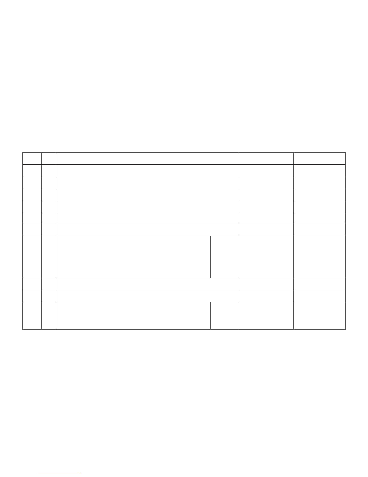
CV Bedeutung Wert DCC Wert Selectrix
1 * Adresse 1 - 127 1 - 99
3 Anfahrverzögerung 0 - 127 1 - 7
4 Bremsverzögerung 0 - 127 1 - 7
5 * Maximalgeschwindigkeit 1 - 7 1 - 7
17 Erweiterte Adresse (oberer Teil) CV 29, bit 5=1 nicht notwendig
18 Erweiterte Adresse (unterer Teil) CV 29, bit 5=1 nicht notwendig
29 bit 0: Umpolung Fahrtrichtung
bit 1: Anzahl Fahrstufen 14/28
bit 2: DCC Betrieb mit Bremsstrecke
DCC-, Selectrix- und Gleichstrombetrieb
bit 5: Adressumfang 7 bit / 14 bit
Wert
0 / 1
0 / 2
0 / 4
0 / 32
***
0. 1, 2, 3, 4, 5, 6,
7, 32, 34, 35, 36,
37, 38, 39
nicht
notwendig
49 * Impulsbreite zur Motorsteuerung 0 - 3 1 - 4
50 * Regelvariante 0 - 3 1 - 4
51 * bit 0: Motorumpolung
bit 1: Umpolung Licht
bit 2: Umpolung Gleis
0 / 1
0 / 2
0 / 4
0 - 7 nicht notwendig
*** Die Werte der gewünschten Einstellungen sind zu addieren!
Page 10

10
• The full functioning of the decoder can only be
guaranteed, when the locomotive is operated with
Trix
Selectrix.
• Not suitable for locomotive controllers with pulse
width control.
• Not suitable for continuous train lighting on analog
layouts.
• Not suitable for Trix-
ems.
• The locomotive must not be connected to more than
one power source at a time.
• This Locomotive ist to be used only with an operat
-
ing system designed for it.
• Pay close attention to the safety warnings in the
instructions for your operating system.
No warranty or damage claims shall be accepted in those cases
where parts neither manufactured nor approved by Trix
have
been installed in Trix products or where Trix products have been
converted in such a way thad the non-Trix parts or the conversion were causal to the defects and/or damage arising.
The burden of presenting evidence and the burden of proof
thereof, that the installation of non- Trix
parts or the conversion
in or of Trix products was not causal to the defects and/or damage arising, is bome by the person and/or company responsible
for the installation and/or conversion, or by the customer.
Note for Selectrix Operation:
When a train enters a braking block that is turned on,
and enters it against the direction of travel, the indicator
light for running trains goes out in the braking block.
After the bracing block, the running light indicator
comes back on.
Notes on digital operation:
• The operating instructions for your central unit
(examplare: Central Control 2000) will give you exact
procedures for setting the different parameters.
• The values set at the factory have been selected to
insure trouble-free operation.
• This locomotive comes from the factory programmed
for the digital address „03“ (Selectrix) / „03“ (DCC).
• This locomotive with the settings made at the factory
cannot be operated with opposed polarity DC power
in braking track blocks. If this feature is desired, then
you must do without conventional DC operation (CV
29 / bit 2=0).
• Malfunctions resulting from changes to the factory
settings of the locomotive electronics are caused by
the operator and do not give grounds for complaint
under our guarantee or warranty obligaions.
• The programming for the Selectrix function is done
in the same mariner as discribed in the instructions
for the 66836 decoder.
Page 11
11
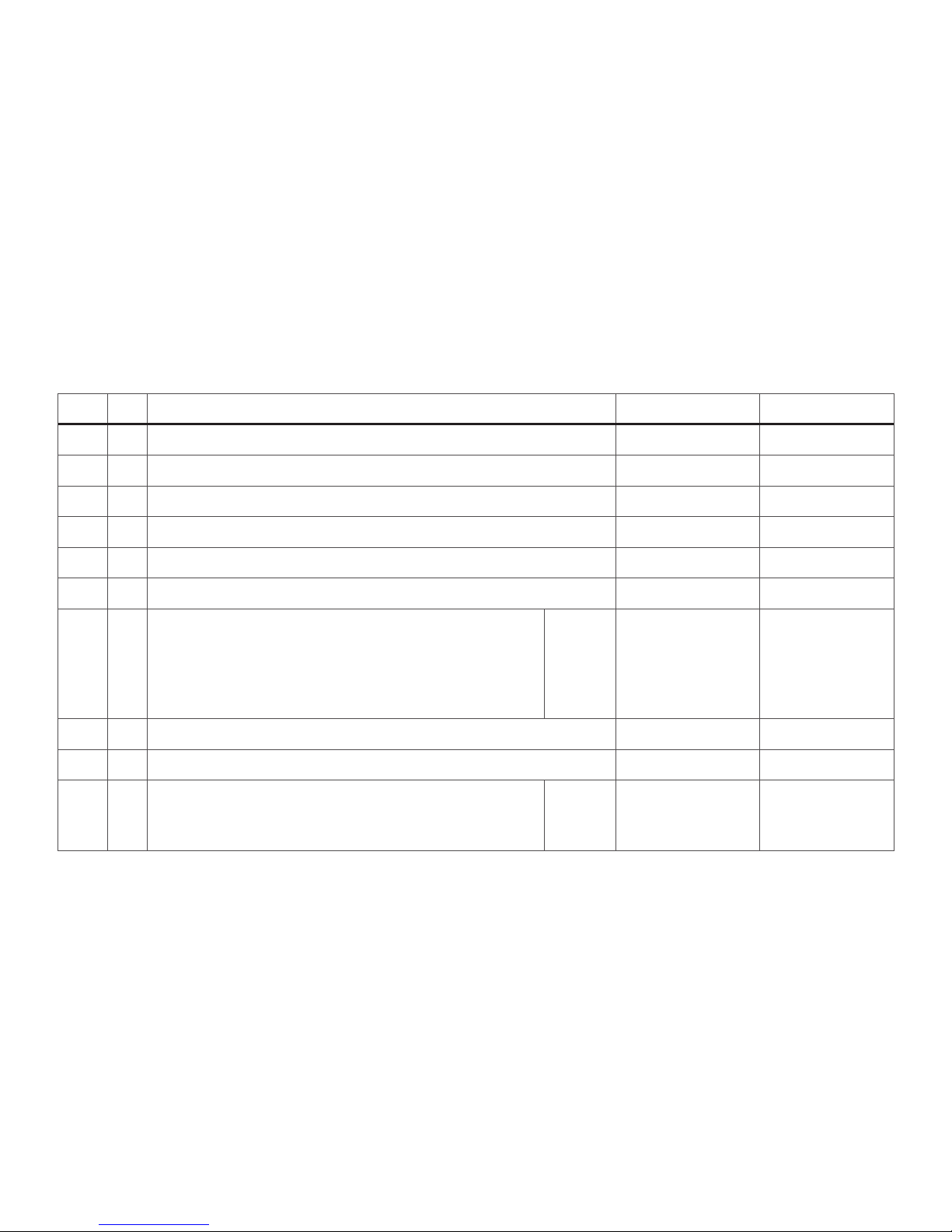
Important: Changes in the settings market with ( * ) for the
Selectrix mode of operation automatically lead to changes in
the DCC mode of operation and versa!
*** The values for the desired settings must be added.
CV Discription DCC Value Selectrix Value
1 * address 1 - 127 1 - 99
3 acceleration delay 0 - 127 1 - 7
4 braking delay 0 - 127 1 - 7
5 * maximum speed 1 - 7 1 - 7
17 extendet address (upper part) CV 29, bit 5=1 not necessary
18 extendet address (lower part) CV 29, bit 5=1 not necessary
29 bit 0: Travel direction polarity reversal
bit 1: number of speed levels 14/28
bit 2: DCC Operation with braking Block
DCC-, Selectrix and DC power operation
bit 5: address size 7 bit / 14 bit
Value
0 / 1
0 / 2
0 / 4
0 / 32
***
0. 1, 2, 3, 4, 5, 6,
7, 32, 34, 35, 36,
37, 38, 39
not
necessary
49 * pulse width for motor control 0 - 3 1 - 4
50 * ule variant 0 - 3 1 - 4
51 * bit 0: motor polarity reversal
bit 1: lighting polarity reversal
bit 2: track polarity reversal
0 / 1
0 / 2
0 / 4
0 - 7 not necessary
Page 12

12
Remarque concernant l‘exploitation Selectrix:
Si une locomotive roule en sens contraire dans une
zone de freinage activée, les feux de signalisation sont
coupés dans cette zone. Une fois la locomotive passée
outre la zone de freinage, les feux se rallument.
Remarques relatives au fonctionement en mode digital:
• En ce qui concerne la procédure de réglage des
divers paramètres, veuillez vous référer au mode
d‘emploi de votre centrale de commande multitrain
(par ex. Central Control 2000).
• Les valeurs encodées en usine ont été sélectionnées
pour garantir une exploitation exempte de problèmes.
•
En usine, c‘est l‘adresse „03“ (Selectrix) / „03“ (DCC) qui
est programmée pour une exploitation digitale de cette
• En cas d‘exploitation numérique DCC, une alimentation des sections de freinage avec du courant continu
de polarité contraire n‘est pas possible à cause des
réglages faits en usine. Si cette option est désirée, il
faut alors renoncer à une exploitation conventionelle
et modifier les réglages (CV 29 / bit 2=0).
• Les défaillances au niveau du fonctionnement, dé
coulant de la modification des réglages faits en usine
sur le système électronique de la locomotive, sont
déclenchées par l‘opérateur et ne constituent par
conséquent aucune raison de réclamation; elles ne
donnent de ce fait aucun droit de recours en garantie
contractuelle ou commerciale.
• La programmation des fonctions de décodeur Selec
trix se fait comme décrit dans le mode d‘emploi du
décodeur 66836.
• La totalité des fonctions du décodeur ne peut être
assurée que par l‘emploi desappareils de commande
Trix
.
• Pas pour appareils de commande avec pilotage par
impulsion de largeur variable.
• Pas pour éclairage de train permanent sur réseaux
analogiques.
• Pas pour Trix-
ems.
• La locomotive ne peut être alimentée que par une
seule source de courant à la fois.
• La locomotive ne peut être mise en service qu‘avec
un système d‘exploitation adéquat.
• Veuillez impérativement respecter les remarques sur
la sécurité décrites dans le mode d‘emploi en ce qui
concerne le système d‘exploitation.
Tout recours à une garantie commerciale ou contractuelle ou à
une demande de dommages-intérét est exclu si des pièces non
autorisées par Trix sont intégrées dans les produits Trix et/ou
si les produits Trix sont transformés et que les pièces d‘auftres
fabricants montées ou la transformation constituent la cause des
défauts et/ou dommages apparus.
C‘est à la persone et/ou la société responsable du montage/de
la transformation ou au client qu‘incombe la charge de prouver
quer le montage des pièces d‘autres fabricants sur des produits
Trix ou la transformation des produits Trix
n‘est pas à l‘origine
des défauts et ou dommages apparus.
Page 13

13
Remarque: Toute modification des réglages repérés par un astérisque
( * ) en mode d’exploitation Selectrix entraînera automatiquement une
modification dans le mode d’exploitation DCC et vece-versa.
*** Les valeurs des réglages désirés sont à additioner.
CV Signification Valieur DCC Valieur Selectrix
Valieur
1 * Adresse 1 - 127 1 - 99
3 Temporisation d‘accélération 0 - 127 1 - 7
4 Temproisation de freinage 0 - 127 1 - 7
5 * Vitesse maximale 1 - 7 1 - 7
17 Adresse étendue (partie supérieure) CV 29, bit 5=1 not nécessaire
18 Adresse étendue (partie inférieure) CV 29, bit 5=1 not nécessaire
29 bit 0: inversion de polarité, sens de marche
bit 1: Nombre de crans de marche 14/28
bit 2: Exploitation DCC avec zone de freinage.
DCC-, Selectrix et courant continu
bit 5: taille d‘adresse 7 bits / 14 bits
Valeur
0 / 1
0 / 2
0 / 4
0 / 32
***
0. 1, 2, 3, 4, 5, 6,
7, 32, 34, 35, 36,
37, 38, 39
not
nécessaire
49 * Largeur d‘impulsion de cammande moteur 0 - 3 1 - 4
50 * Variante de réglage 0 - 3 1 - 4
51 * bit 0: inversion de polarité du moteur
bit 1: phares seulement
bit 2: inversion de polaritè
0 / 1
0 / 2
0 / 4
0 - 7 not nécessaire
Page 14

14
• Het volledig functioneren van de decoder kan alleen
gegarandeerd worden in combinatie met de Trix
-
Selectrix besturingsapparaten.
• Niet geschikt voor het gebruik met rijregelaars met
impuls-breedte-sturing.
• Niet geschikt voor het gebruik op analoge banen met
continue-treinverlichting.
• Niet geschikt voor het Trix
-ems systeem.
• De loc mag niet met meer dan één stroombron
gelijktijdig verbonden worden.
• De loc mag alleen met een daar voor bestemd
bedrijfssysteem gebruikt worden.
• Lees ook aandachtig de veiligheidsvoorschriften in
de gebruiksaanwijzing van uw bedrijfssysteem.
Elke aanspraak op garantie en schadevergoeding is uitgesloten,
wenneer in Trix-producten niet door Trix vrijgegeven vreemde
onderdelen ingebouwd en/of Trix-producten omgebouwd wor
den en de ingebouwde vreemde onderdelen resp.de ombouw
oorzaak van nadien opgetreden defecten en/of schade was.
De aantoonplicht en de bewijslijst daaromtrent, dat de inbouw
van vreemde onderdelen in Trix-producten niet de oorzaak van
opgetreden defekten en/of schade is geweest, berust dij de voor
de inbouw en/of ombouw verantwoordelijke person en/of firma
danwel bij de klant.
Opmerking voor het Selectrix-bedrijf:
Indien een afremtraject tegen de rijrichting in bereden
wordt, dooft de frontverlichting van de trein. na het
passeren van het afremtrajeck gaat de fronverlichting
weer aan.
Aanwijzingen voor digitale besturing:
• Het op de juiste wijze instellen van de diverse para
meters staat beschreven in de handleiding van uw
digitale Centrale (bijv. Central Control 2000).
• De vanaf de fabriek ingestelde waarden zijn zo geko
-
zen dat een probleemloos bedrijf gewaarborgd is.
• Vanaf de fabriek is deze loc geprogrammeerd op het
digitale adres „03“ (Selectrix) /“03“ (DCC).
• Het bedrijf met omgepoolde gelijkspanning in afrem
trajecten bij het DCC-bedrijf is, met de fabrieksinstelling, niet mogelijk. Indien deze eigenschap
gewenst wordt dan moet afgezien worden van het
conventionele gelijdstroombedrijf (CV 29 / bit 2=0).
• Funktionsroringen die door wijziging van de fabriks
matige instellingen van loc-elektronica veroorzaakt
worden, zijn aan de gebruiker zelf te wijten en der
halve geen gerede grond voor reclamering op basis
van de garantie- en aansprakelijkheidsaanspraken.
• Het programmeren van de Selectrix-functies ge
beurd zoals in de gebruiksaanwijzing van de decoder
66836 beschreven is.
Page 15

15
Opmerking: wijzigengen van de met een ( * ) gemerkte instellingen in de bedrijfmodus Selectrix leiden automatisch ook tot
wijzigingen in de bedrijfsmodus DCC en omgekeerd.
*** De waarden van de gewenste instellingen moeten bij elkaar opgeteld worden.
CV Betekenis Waarde DCC Warde Selec-
trix
1 * adres 1 - 127 1 - 99
3 optrekvertraging 0 - 127 1 - 7
4 afremvertraging 0 - 127 1 - 7
5 * maximumsnelheid 1 - 7 1 - 7
17 uitgebreld adres (bovenste gedeelte) CV 29, bit 5=1 niet nodig
18 uitgebreld adres (onderste gedeelte) CV 29, bit 5=1 niet nodig
29 bit 0: ompoling rijrichting
bit 1: aantal rijstappen 14/28
bit 2: DCC-bedrijf met afremtraject.
DCC-, Selectrix- en gelijkstroombedrijf
bit 5: adresbereik 7 bit / 14 bit
Waarde
0 / 1
0 / 2
0 / 4
0 / 32
***
0. 1, 2, 3, 4, 5, 6,
7, 32, 34, 35, 36,
37, 38, 39
niet
nodig
49 * impulsbreedte voor de motorsturing 0 - 3 1 - 4
50 * relingsvariant 0 - 3 1 - 4
51 * bit 0: motorompoling
bit 1: allen verlichting
bit 2: ompoling rails
0 / 1
0 / 2
4 / 0
0 - 7 niet nodig
Page 16

Im Falle von Reparaturen oder Reklamationen wenden
Sie sich bitte an folgende Service-Adresse:
Trix Modelleisenbahn GmbH & Co. KG
Service Minitrix
Trautskirchenerstr. 6/8
90431 Nürnberg
108255/0805/SmEf
Änderungen vorbehalten
© Trix Modelleisenbahn
Trix Modelleisenbahn GmbH & CO. KG
Postfach 4924
D-90027 Nürnberg
www.trix.de
14 V analog
22 V digital
~
www.maerklin.com/api
 Loading...