

Page 1
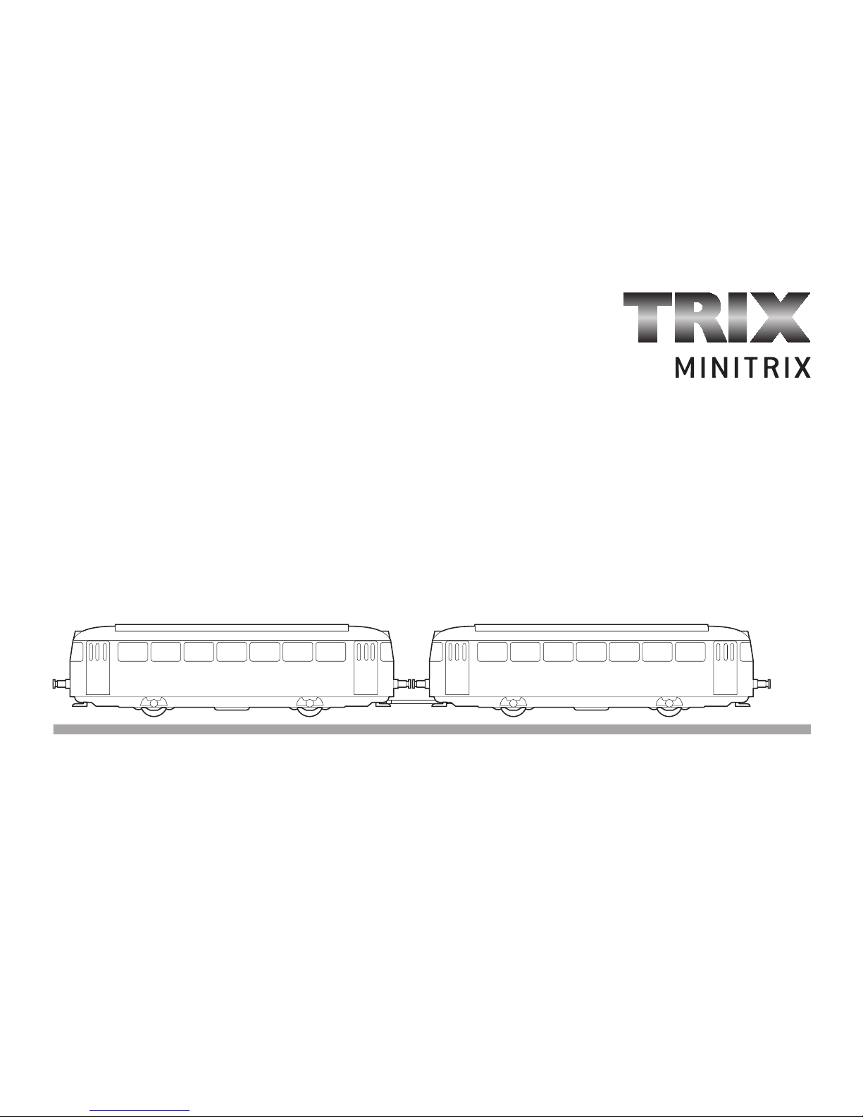
Modell des VT 98, Schienenbus
12555
Page 2

2
Informationen zum Vorbild
Zu Beginn der 50er Jahre musste die DB den Betrieb auf Nebenbahnen wegen der Konkurrenz des PKW rationeller durchführen. 1950
lieferte Uerdingen einmotorige Schienenbusse mit 4.500 mm
Achsstand und 110 PS Motorleistung und ab 1952 insgesamt 572
Fahrzeuge der Baureihe VT 95. Bald schon zeigte sich, dass die
Motorleistung und der Antrieb auf nur eine Achse nicht immer
ausreichend war. Daher wurden bereits 1952 drei zweimotorige
Fahrzeuge gebaut, die sonst dem VT 95 vollständig entsprachen.
Ab 1955 erstellte Uerdingen insgesamt 332 Triebwagen der
Baureihe VT 98 mit einer Motorleistung von 2 x 150 PS und einer
Höchstgeschwindigkeit von 90 km/h, dazu 310 Steuerwagen VS 98
und 320 Beiwagen VT 98. Alle Fahrzeuge hatten einen Achsstand
von 6.000 mm und gleiche Länge. Im Gegensatz zu den VT 95 und
den VT 98 Prototypen waren normale Puffer und Schraubenkupplungen angebaut.
1968 wurden die Schienenbusse in das neue Nummernschema
eingeordnet. Der Motorwagen wurde zur BR 798, der Steuerwagen BR
898 und der Beiwagen BR 998.
Achsanordnung AA‘
Höchstgeschwindigkeit 90 km/h
Dienstmasse 18,9 t
Nennleistung 2 x 112 kW
(2 x 150 PS )
Baujahr ab 1953
Wheel arrangement A-A
Maximum speed 90 km/h, 56 mph
Service weight 18,9 metric tons, 56 mph
Nominal power 2 x 112 kW
(2 x 150 hp)
Built starting in 1953
Information about the Prototype
At the start of the Fifties the DB had to rationalize the operation of its
branch lines due to competition from automobiles. In 1950, a singlemotor rail bus with a wheelbase of 4,500 mm / 14 feet 9-3/16 inches
and a power output of 110 hp was built. A total of 572 units of the
class VT 95 were delivered starting in 1952. It was soon determined
that the power output and running gear with only single axle powered
was not always enough. Three two-motor units were therefore built as
early as 1952 that were otherwise identical to the VT 95.
A total of 332 of the class VT 98 with a power output of 2 x 150 hp
and a maximum speed of 90 km/h / 56 mph were delivered starting
in 1955 along with 310 class VS 98 control cars and 320 class
VB 98 trailer cars. All of these units had a wheelbase of 6,000 mm /
19 feet 8-1/4 inches and the same overall length. Standard buffers
and prototype couplers were installed on these cars in contrast to
the VT 95 and VT 98 prototypes.
In 1968, the rail busses were put into the new numbering system.
The powered rail busses became the class 798, the control cars the
class 898, and the trailer cars the class 998.
Page 3

3
Disposition d‘essieux AA‘
Vitesse maximale 90 km/h
Poids en ordre de marche 18,9 t
Puissance nominale 2 x 112 kW
(2 x 150 PS)
Construction à partir de 1953
Asopstelling AA‘
Maximumsnelheid 90 km/h
Dienstgewicht 18,9 t
Nominaal vermogen 2 x 112 kW
(2 x 150 PS)
Bouwjaar vanaf 1953
Informations concernant le modèle réel
Du fait de la concurrence du transport routier au début des années
cinquante, la DB fut amenée à rationaliser l’exploitation des lignes de
chemins de fer secondaires. En 1950 furent construits des autorails
monomoteurs avec un empattement rigide de 4500 mm et une puissance
de 110 ch. A partir de 1952 furent livrés au total 572 véhicules de la
série VT 95. Il s’avéra rapidement que la puissance du moteur et la
transmission sur un seul essieu n’étaient pas toujours suffisantes. C’est
pourquoi trois véhicules bimoteurs, qui correspondaient par ailleurs
entièrement au VT 95, furent construits dès 1952.
A partir de 1955 furent livrées 332 automotrices de la série VT 98 avec
une puissance moteur de 2 x 150 ch et une vitesse maximale de 90
km/h ainsi que 310 voitures-pilotes VS 98 et 320 remorques VB 98. Tous
les véhicules possédaient un empattement rigide de 6000 mm et une
longueur identique. Contrairement aux prototypes VT 95 et VT 98, les
véhicules étaient équipés de tampons normaux et d’attelages à vis.
En 1968, les autorails furent intégrés dans le nouveau système
d’immatriculation. La voiture motrice devint ainsi la BR 798, la voiturepilote la BR 898 et la remorque la BR 998.
Informatie over het voorbeeld
Aan het begin van de vijftiger jaren moest de DB het bedrijf op de
neventrajecten rationaliseren vanwege de concurrentie met de auto.
In 1950 werden de railbussen met een asafstand van 450 en een
motorvermogen van 110 pk gebouwd. Vanaf 1952 werden in totaal
572 voertuigen van de serie VT 95 geleverd. Al snel werd duidelijk
dat het motorvermogen en de aandrijving op één as niet altijd
toereikend waren. Daarom werden er in 1952 al drie tweemotorige
voertuigen gebouwd, die verder identiek waren aan de VT 95.
Vanaf 1955 werden er in totaal 332 treinstellen van de serie VT 98 met
een motorvermogen van 2 x 150 pk en een maximumsnelheid van
90 km/h geleverd. Daarnaast nog 310 stuurstandrijtuigen VS 98 en
320 bijwagens VB 98. Alle voertuigen hadden een asafstand van 6000
mm en waren even lang. In tegenstelling tot de prototypes van de VT
95 en de VT 98, waren er echter normale buffers en schroefkoppelin
-
gen aangebracht.
In 1968 werd de railbus in het nieuwe nummerschema opgenomen.
Het motorrijtuig werd BR 798, het stuurstandrijtuig BR 898 en de
bijwagen BR 998.
Page 4

4
Funktionen
• Eingebaute Elektronik zum wahlweisen Betrieb mit konventionel
lem Gleichstrom-Fahrgerät, TRIX Selectrix oder Digitalsystemen
nach NMRA-Norm (DCC).
• Automatische Systemerkennung zwischen Digital- und
Analog-Betrieb.
• Keine automatische Systemerkennung zwischen Selectrix (SX)
und DCC.
• Der volle Funktionsumfang ist nur unter Selectrix 2 (SX2) und
unter DCC verfügbar.
• Dreilicht-Spitzensignal vorne, zwei weiße Schlusslichter hinten,
mit der Fahrtrichtung wechselnd.
• Innenbeleuchtung eingebaut.
• Beleuchtung mit wartungsfreien LED.
• analog 14 Volt=, digital 22 Volt~
• Der Triebzug kann mit dem ebenfalls beleuchteten Zwischenwa
-
gen 15855 ergänzt werden.
Hinweise zum Digitalbetrieb:
• Beim ersten Betrieb in einem Digital-System (Selectrix oder
DCC) muss der Decoder auf dieses Digital-System eingestellt
werden. Dazu ist der Decoder ein mal in diesem Digitalsystem
zu programmieren.
• Trieb- und Steuerwagen sind getrennt von einander zu program
mieren und sind dazu jeweils einzeln auf das Gleis zu stellen.
Am Steuerwagen ist nur die Adresse (gleich wie im Motorwagen)
zu programmieren. Am Steuerwagen muss nur die Adresse
(gleich wie im Motorwagen) programmiert werden.
• Die genaue Vorgehensweise zum Einstellen der diversen
Parameter entnehmen Sie bitte der Bedienungsanleitung Ihrer
Mehrzug-Zentrale.
• Die ab Werk eingestellten Werte sind so gewählt, dass ein
problemloser Betrieb gewährleistet ist.
• Ab Werk ist bei dieser Lok für Digitalbetrieb die Adresse „01“
(Selectrix) / „03“ (DCC) programmiert.
• Ein Betrieb mit gegenpoliger Gleichspannung in Bremsabschnit
ten bei DCC-Betrieb ist mit der werkseitigen Einstellung nicht
möglich. Ist diese Eigenschaft gewünscht, so muss auf den
konventionellen Gleichstrom-Betrieb verzichtet werden
(CV 29 / Bit 2=0).
Sicherheitshinweise
• Beachten Sie unbedingt die Sicherheitshinweise in der Ge
-
brauchsanleitung zu Ihrem Betriebssystem.
• Die Fahrspannung ist immer langsam und gleichmäßig zu erhö
-
hen.
• Im Gleichstrombetrieb sind die Fahreigenschaften der Lok vom
verwendeten Fahrregler abhängig.
Nicht für:
• Fahrgeräte mit Impulsbreitensteuerung.
• Dauerzugbeleuchtung auf Analog-Anlagen.
• Trix ems.
Jegliche Garantie-, Gewährleistungs- und Schadensersatzansprüche sind ausgeschlossen, wenn in Trix-Produkten nicht von Trix freigegebene Fremdteile eingebaut werden und/oder Trix-Produkte umgebaut werden und die eingebauten
Fremdteile bzw. der Umbau für sodann aufgetretene Mängel und/oder Schäden
ursächlich war. Die Darlegungs- und Beweislast dafür, dass der Einbau von
Fremdteilen oder der Umbau in bzw. von Trix-Produkten für aufgetretene Mängel
und/oder Schäden nicht ursächlich war, trägt die für den Ein- und/ oder Umbau
verantwortliche Person und/ oder Firma bzw. der Kunde.
Page 5
5
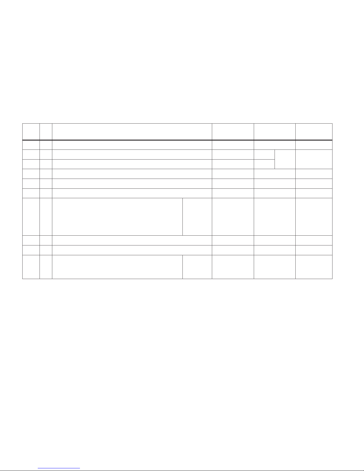
* Änderungen dieser Werte unter Selectrix führen automatisch auch zu Änderungen der Werte unter DCC und umgekehrt!
*** Die Werte der gewünschten Einstellungen sind zu addieren!
CV Bedeutung Wert DCC
ab Werk
DCC / SX1
Wert SX1
1 7-bit Adresse 0 - 127 3 / 1 0 - 111
3
*
Anfahrbeschleunigung 0 - 255 3
3 1 - 7
4
*
Bremsverzögerung 0 - 255 3
5
*
Maximalgeschwindigkeit 0 - 255 7 / 7 1 - 7
17 Erweiterte Adresse (oberer Teil) CV 29, bit 5 =1 255 / — —
18 Erweiterte Adresse (unterer Teil) CV 29, bit 5 =1 255 / — —
29
bit 0: Umpolung Fahrtrichtung
bit 1: Anzahl Fahrstufen 14 oder 28/128
bit 2: DCC Betrieb mit Bremsstrecke
(kein Analogbetrieb möglich)
bit 5: Adressumfang 7 bit / 14 bit
0 / 1
0 / 2
0 / 4
0 / 32
***
0, 1, 2, 3, 4, 5, 6,
7, 32, 34, 35, 36,
37, 38, 39
6 / — —
49
*
Impulsbreite zur Motorsteuerung 0 - 3 1 / 2 1 - 4
50
*
Regelvariante 0 - 3 2 / 3 1 - 4
51
*
bit 0: Motorumpolung
bit 1: Umpolung Licht
bit 2: Umpolung Gleis
0 / 1
0 / 2
0 / 4
***
0 - 7
0 / 4 4
Page 6

6
Functions
• Built-in electronic circuit for oberation with an conventional DC
power pack, Trix Selectrix or NMRA DCC digital.
• Automatic system recognition between digital and analog
operation.
• No automatic system recognition between Selectrix (SX) and DCC.
• The full range of functions is only available under Selectrix 2
(SX2) and under DCC.
• Triple headlights in the front, dual white marker lights in the rear
that change over with the direction of travel.
• Interior lighting built in.
• Maintenance-free LEDs for lighting.
• Analog 14 volts DC, digital 22 volts AC
• The 15855 (also lighted) intermediate car can be added to the
powered rail car train.
Notes on digital operation:
• The first time the locomotive is used in a digital system (Selectrix
or DCC), the decoder must be set for this digital system. To do this,
the decoder must be programmed once in this digital system.
• Motor and control cars cannot be programmed simultaneously.
They must be programmed separately from each other and they
must be placed individually on the track for this purpose. Only the
address (the same as in the motor car) must be programmed in
the control car.
• The operating instructions for your central unit will give you exact
procedures for setting the different parameters.
• The values set at the factory have been selected to insure
trouble-free operation.
• This locomotive comes from the factory programmed for the
digital address „01“ (Selectrix) / „03“ (DCC).
• This locomotive with the settings made at the factory cannot be
operated with opposed polarity DC power in braking track blocks.
If this feature is desired, then you must do without conventional
DC operation (CV 29 / bit 2=0).
Safety Information
• Pay close attention to the safety warnings in the instructions for
your operating system.
• Always increase the track voltage slowly and evenly.
• In DC operation the locomotive‘s running characteristics depend
on the speed controller you are using.
Not suitable for:
• Locomotive controllers with pulse width control.
• Continuous train lighting on analog layouts.
• Trix ems.
No warranty or damage claims shall be accepted in those cases where parts
neither manufactured nor approved by Trix have been installed in Trix products or
where Trix products have been converted in such a way that the non-Trix parts or
the conversion were causal to the defects and/or damage arising. The burden of
presenting evidence and the burden of proof thereof, that the installation of nonTrix parts or the conversion in or of Trix products was not causal to the defects
and/or damage arising, is borne by the person and/or company responsible for
the installation and/or conversion, or by the customer.
Page 7

7
CV Discription DCC Value
Factory-Set
DCC / SX1
SX1 Value
1 7-bit Adress 0 - 127 3 / 1 0 - 111
3
*
Acceleration delay 0 - 255 3
3 1 - 7
4
*
Braking delay 0 - 255 3
5
*
Maximum speed 0 - 255 7 / 7 1 - 7
17 Extended address (upper part) CV 29, bit 5 =1 255 / — —
18 Extended address (lower part) CV 29, bit 5 =1 255 / — —
29
bit 0: Travel direction polarity reversal
bit 1: number of speed levels 14 or 28/128
bit 2: DCC Operation with braking Block.
DCC-, Selectrix- and DC power Operation
bit 5: Adress size 7 bit / 14 bit
0 / 1
0 / 2
0 / 4
0 / 32
***
0, 1, 2, 3, 4, 5, 6,
7, 32, 34, 35, 36,
37, 38, 39
6 / — —
49
*
pulse width for motor control 0 - 3 1 / 2 1 - 4
50
*
ule variant 0 - 3 2 / 3 1 - 4
51
*
bit 0: Motor polarity reversal
bit 1: Headlight polarity reversal
bit 2: Track polarity reversal
0 / 1
0 / 2
0 / 4
***
0 - 7
0 / 4 4
* Changes to these values in Selectrix also lead automatically to changes to the values in DCC and vice versa!
*** The values for the desired settings must be added.
Page 8

8
Functies
• Electronique intégrée pour exploitation au choix avec transforma
teur-régulateur conventionnel délivrant du courant continu, avec
Selectrix ou avec des sastèmes de vonduite digitale conformes aux
normes NMRA.
• Reconnaissance automatique du système entre exploitations
numérique et analogique.
• Pas de reconnaissance automatique entre les systèmes
Selectrix (SX) et DCC.
• L’intégralité des fonctions est disponible uniquement en exploita
-
tion Selectrix 2 (SX2) et DCC.
• Feux triples à l‘avant, deux feux blancs de fin de convoi à l‘arrière,
avec alternance selon sens de marche.
• Eclairage intérieur intégré.
• Eclairage assuré par diodes sans entretien.
• Analogique 14 volts =, digital 22 volts ~
• La rame automotrice peut être complétée par la voiture intermé
-
diaire réf. 15855, également éclairée.
Remarques relatives au fonctionement en modedigital:
• Une première exploitation en système numérique (Selectrix ou DCC)
exige le réglage correspondant du décodeur. A cet effet, le déco
-
deur doit être programmé une fois dans ce système numérique.
• La voiture motrice et la voiture pilote ne peuvent pas être
programmées simultanément.
Elles doivent être programmées l’une après l‘autre et pour cela
placées séparément sur la voie. Sur la voiture pilote, seule
l‘adresse doit être programmée (comme sur la voiture motrice).
• En ce qui concerne la procédure de réglage des divers paramè
tres, veuillez vous référer au mode d‘emploi de votre centrale de
commande multitrain.
• Les valeurs encodées en usine ont été sélectionnées pour garantir
une exploitation exempte de problèmes.
•
En usine, c‘est l‘adresse „01“ (Selectrix) / „03“ (DCC) qui est programmée pour une exploitation digitale de cette locomotive.
• En cas d‘exploitation numérique DCC, une alimentation des
sections de freinage avec du courant continu de polarité contraire
n‘est pas possible à cause des réglages faits en usine. Si cette
option est désirée, il faut alors renoncer à une exploitation conven
-
tionelle et modifier les réglages (CV 29 / bit 2=0).
Remarque sur la sécurité
• Veuillez impérativement respecter les remarques sur la sécurité
décrites dans le mode d’ emploi en ce qui concerne le système
d’ exploitation.
• La tension de traction doit toujours être augmentée lentement
et de manière régulière.
• En exploitation sous courant continu, les qualités de roulement
de la loco dépendent du régulateur de marche utilisé.
Pas pour:
• appereils de commande avec pilotage par impulsion de largeur
variable.
• éclairage de train permanent sur réseaux analogigues.
• Trix ems.
Tout recours à une garantie commerciale ou contractuelle ou à une demande de
dommages-intérêt est exclu si des pièces non autorisées par Trix sont intégrées
dans les produits Trix et/ou si les produits Trix sont transformés et que les pièces
d‘autres fabricants montées ou la transformation constituent la cause des défauts
et/ou dommages apparus. C‘est à la personne et/ou la société responsable du
montage/de la transformation ou au client qu‘incombe la charge de prouver que le
montage des pièces d‘autres fabricants sur des produits Trix ou la transformation
des produits Trix n‘est pas à l‘origine des défauts et ou dommages apparus.
Page 9

9
CV Signification Vaieur DCC Valeur
Parm. Usine
DCC / SX1
SX1 Valeur
1 7-bit Adresse 0 - 127 3 / 1 0 - 111
3
*
Temporisation d‘accélération
0 - 255 3
3 1 - 7
4
*
Temporisation de freinage
0 - 255 3
5
*
Vitesse maximale
0 - 255 7 / 7 1 - 7
17 Adresse étendue (partie supérieure) CV 29, bit 5 =1 255 / — —
18 Adresse étendue (partie inférieure) CV 29, bit 5 =1 255 / — —
29
bit 0: inversion de polarité, sens de marche
bit 1: Nombre de crans de marche 14 ou 28/128
bit 2: Exploitation DCC avec zone de freinage.
DCC, Selectrix et courant continu
bit 5: taille d‘adresse 7 bit / 14 bit
0 / 1
0 / 2
0 / 4
0 / 32
***
0, 1, 2, 3, 4, 5, 6,
7, 32, 34, 35, 36,
37, 38, 39
6 / — —
49
*
0 - 3 1 / 2 1 - 4
50
*
0 - 3 2 / 3 1 - 4
51
*
bit 0: inversion de polarité du moteur
bit 1: inversion éclairage
bit 2: inversion de polaritè
0 / 1
0 / 2
0 / 4
***
0 - 7
0 / 4 4
* La modification de ces valeurs sous Selectrix génère automatiquement la modification des valeurs sous DCC et inversement !
*** Les valeurs des réglages désirés sont à additioner.
Page 10

10
Fonctionnement
• Ingebouwde elektronica die het mogelijk maakt om naar keuze
met, een conventionele gelijkstromrijregelaar, Trix Selectrix of
digitaalsysteem volgens NMRA-norm te rijden.
• Automatische systeemherkenning tussen digitaal- en analoogbedrijf.
• Geen automatische herkenning tussen Selectrix (SX) en DCC.
• De volledige toegang tot alle functies is alleen mogelijk met
Selectrix 2 (SX2) of met DCC bedrijf.
• Drievoudige frontverlichting voor, twee witte sluitseinen achter,
wisselend met de rijrichting.
• Binnenverlichting ingebouwd.
• Verlichting met onderhoudsvrije LED.
• Analoog 14 Volt=, digitaal 22 Volt ~
• Het treinstel kan met het eveneens verlichte tussenrijtuig 15855
uitgebreid worden.
Aanwijzingen voor digitale besturing:
• Voor het eerste bedrijf met een digitaal-systeem (Selectrix of DCC)
moet de decoder op dat digitale systeem worden ingesteld. Daarvoor
moet de decoder éénmaal met dat digitale systeem geprogram
-
meerd worden.
• Motor- en stuurstandrijtuig kunnen niet gelijktijdig geprogrammeerd
worden. Ze dienen gescheiden van elkaar geprogrammeerd te
worden en moeten daarvoor elk apart op de rails worden geplaatst.
In het stuurstandrijtuig hoeft alleen het adres (hetzelfde als in het
motorrijtuig) geprogrammeerd te worden.
• Het op de juiste wijze instellen van de diverse parameters staat
beschreven in de handleiding van uw digitale Centrale.
• De vanaf de fabriek ingestelde waarden zijn zo gekozen dat een
probleemloos bedrijf gewaarborgd is.
• Vanaf de fabriek is deze loc geprogrammeerd op het digitale
adres „01“ (Selectrix) /“03“ (DCC).
• Het bedrijf met omgepoolde gelijkspanning in afremtrajecten bij
het DCC-bedrijf is, met de fabrieksinstelling, niet mogelijk. Indien
deze eigenschap gewenst wordt dan moet afgezien worden van
het conventionele gelijdstroombedrijf (CV 29 / bit 2=0).
Veiligheidsvoorschriften
• Lees ook aandachtig de veilighedsvoorschriften in de gebruiks
-
aanwijzing van uw bedrijfssysteem.
• De rijspanning moet altijd langzaam verhoogd worden.
• In het gelijkstroombedrijf zijn de rijeigenschappen van de loc
afhankelijk van de gebruikte rijregelaar.
Niet geschikt voor:
• Het gebruik met rijregelaars met impuls-breedtesting.
• Het gebruik op analoge banen met continuetrein-verlichting.
• Het Trix-ems systeem.
Elke aanspraak op garantie en schadevergoeding is uitgesloten, wanneer in
Trix-producten niet door Trix vrijgegeven vreemde onderdelen ingebouwd en/of
Trix-producten omgebouwd worden en de ingebouwde vreemde onderdelen
resp. de ombouw oorzaak van nadien opgetreden defecten en/of schade was.
De aantoonplicht en de bewijslijst daaromtrent, dat de inbouw van vreemde onderdelen in Trix-producten of de ombouw van Trix-producten niet de oorzaak van
opgetreden defecten en/of schade is geweest, berust bij de voor de inbouw en/of
ombouw verantwoordelijke persoon en/of firma danwel bij de klant.
Page 11

11
CV Betekenis Waarde DCC
Af fabriek
DCC / SX1
Waarde SX1
1 7-bit Adres 0 - 127 3 / 1 0 - 111
3
*
Optrekvertraging 0 - 255 3
3 1 - 7
4
*
Afremvertraging 0 - 255 3
5
*
Maximumsnelheid 0 - 255 7 / 7 1 - 7
17 Uitgebreld adres (bovenste gedeelte) CV 29, bit 5 =1 255 / — —
18 Uitgebreld adres (onderste gedeelte) CV 29, bit 5 =1 255 / — —
29
bit 0: ompoling rijrichting
bit 1: aantal rijstappen 14 of 28/128
bit 2: DCC-bedrijf met afremtraject.
DCC-, Selectrix- en gelijkstroombedrijf
bit 5: adresbereik 7 bit / 14 bit
0 / 1
0 / 2
0 / 4
0 / 32
***
0, 1, 2, 3, 4, 5, 6,
7, 32, 34, 35, 36,
37, 38, 39
6 / — —
49
*
Largeur d‘impulsion de cammande moteur 0 - 3 1 / 2 1 - 4
50
*
Variante de réglage
0 - 3 2 / 3 1 - 4
51
*
bit 0: motorompoling
bit 1: ompoling licht
bit 2: ompoling rails
0 / 1
0 / 2
0 / 4
***
0 - 7
0 / 4 4
* Het wijzigen van deze waarde onder Selectrix wordt automatisch ook doorgevoerd onder DCC en omgekeerd!
*** De waarde van de gewenste instellingen moeten bij elkaar opgeteld worden.
Page 12
12
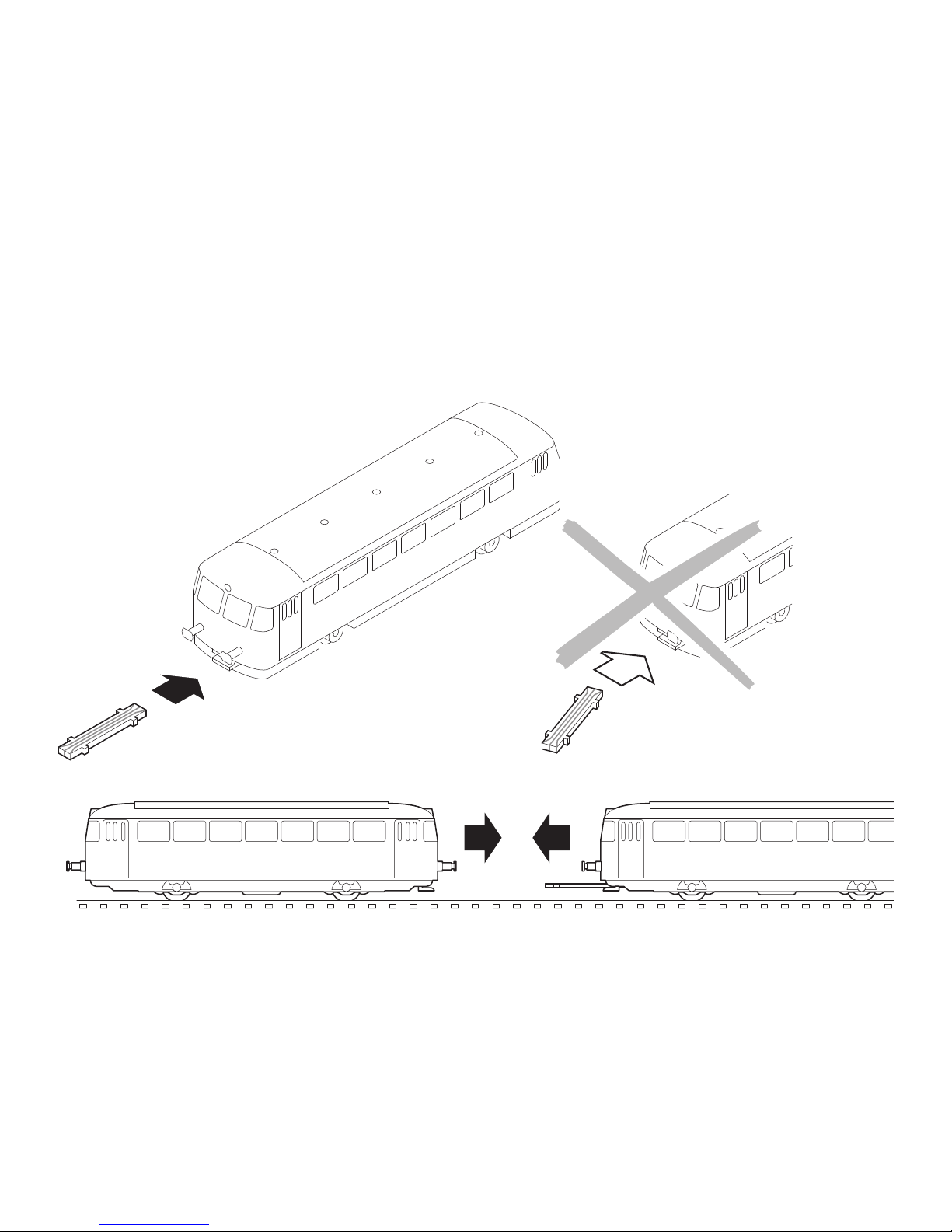
Triebzug mit der stromführenden Kupplung zusammenkuppeln. Die Kupplung muss einrasten!
Couple the powered rail car train together with the current-conducting coupling. The coupling must snap into place!
Atteler la rame automotrice avec l‘attelage conducteur de courant. L’attelage doit s’enclencher !
Het treinstel met de stroomvoerende koppelingen aan elkaar koppelen. De koppelingen moeten goed vastklikken!
b
a
Kupplung immer nur gerade einstecken!
Always insert the coupler straight on, not at an angle!
Toujours enficher l’attelage en alignement !
Koppeling er altijd recht in steken!
Page 13
13
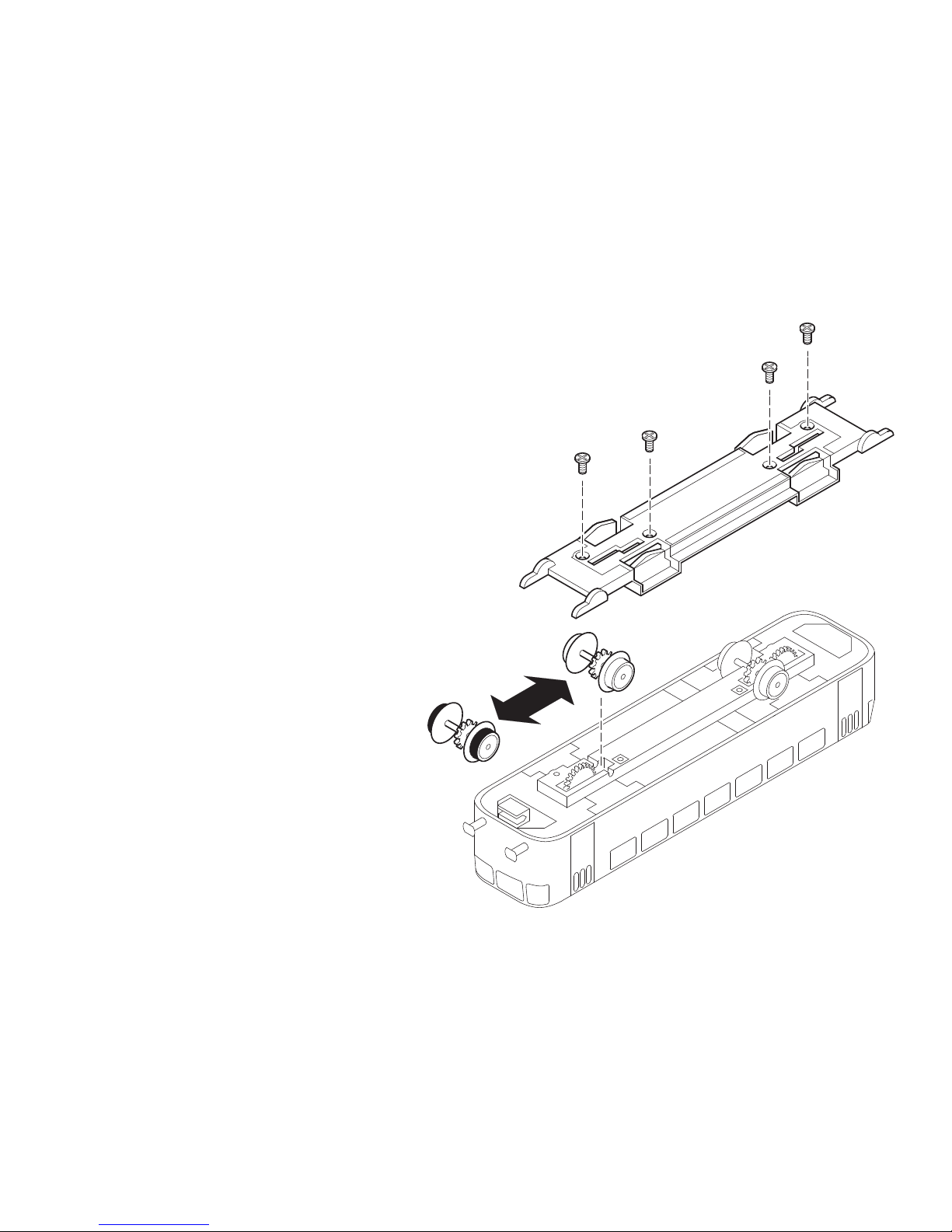
Hinweis:
Für den Betrieb des Motorwagens ohne Zwischenoder Steuerwagen muss der hintere Radsatz mit Haftreifen gegen den beiliegenden Radsatz ohne Haftreifen
getauscht werden.
Note:
To operate the motor car without an intermediate car
or control car, the rear wheel set with traction tires
must be replaced by the wheel set without traction tires
included with this model.
Remarque :
Pour l’exploitation de la voiture-moteur sans voiture
intermédiaire et sans voiture-pilote, l’essieu arrière
avec bandage d‘adhérence doit étre échangé contre
l‘essieu fourni sans bandage d‘adhérence.
Opmerking:
voor het bedrijf met het motorrijtuig zonder tussen- of
stuurstandrijtuig dient de achterste wielas met antislipbanden vervangen te worden door de meegeleverde
wielas zonder antislipbanden.
Page 14

14
Schmierung nach etwa 50 Betriebsstunden
Lubricate after about 50 hours of operation
Graissage environ toutes les 50 heures de fonctionnement
Smeren na ongeveer 50 bedrijfsuren
Reinigung der Lokräder
Cleaning the locomotive wheels
Nettoyage des roues de locomotive
Reiniging van de wielen van de loc
66625 66626
Spezialöl
mit Tropfnadel
O
I
L
66623
Page 15

15
Gehäuse abnehmen
Removing the body
Enlever la caisse
kap verwijderen
a
b
c
Page 16

16
Motor ausbauen
Removing the motor
Enlever le moteur
Motor uitbouwen
Page 17
17
1
2
3
2
3
5
7
4
8
9
6
5
11
12
13
14
17
19
20
19
18
16
15
13
12
11
10
3
Page 18

18
21
22
23
25
28
29
32
31
30
23
21
26
24
27
25
33
34
36
38
39
40
19
41
19
39
37
35
Page 19

19
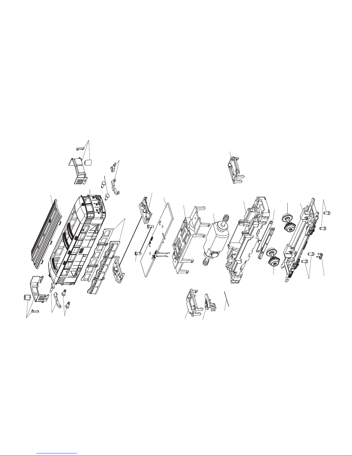
Motorwagen
1 Dach 110 236
2 Leuchtstäbe 114 227
3 Fenstersortiment 114 228
4 Gehäuse 110 234
5 Puffer 110 539
6 Führerstand 110 247
7 Zylinderschraube 101 062
8 Leiterplatte / Decoder 114 058
9 Motorhalter 110 279
10 Motor 110 277
11 Beleuchtungseinheit 139 198
12 Kupplungsträger 110 261
13 Federstab 15 0987 00
14 Rahmen 110 251
15 Schleiferplatte 110 267
16 Radsatz 110 273
17 Radsatz mit Haftreifen 128 702
18 Achshalter 110 281
19 Zylinderschraube 19 7099 28
20 Indusi 110 540
Steuerwagen
21 Dach 110 310
22 Leuchtstäbe oben 114 227
23 Fenstersortiment 114 084
24 Gehäuse 110 308
25 Puffer 110 539
26 Leuchtstab unten 110 245
27 Sitzgruppe 110 294
28 Führerstand 110 247
29 Zylinderschraube 101 062
30 Leiterplatte / Decoder 114 226
31 Inneneinrichtung 110 313
32 Beleuchtungseinheit 139 198
33 Kupplungshalter 110 266
34 Kupplungsträger 110 261
35 Rahmen 110 297
36 Federstab 15 0987 00
37 Schleiferplatte 110 267
38 Kuppelstange 110 303
39 Radsatz 110 300
40 Achshalter 110 302
41 Indusi 110 540
Page 20

126898/0808/SmSk
Änderungen vorbehalten
© by Trix Modelleisenbahn
Im Falle von Reparaturen oder Reklamationen wenden Sie
sich bitte an folgende Service-Adresse:
Trix Modelleisenbahn GmbH & Co. KG
Reparatur-Service
Witschelstraße 104
D-90431 Nürnberg
Trix Modelleisenbahn GmbH & Co. KG
Stuttgarter Str. 55-57
73033 Göppingen
www.trix.de
 Loading...