

Page 1

Modell der Dampfl ok BR 96.2
22053
Page 2

2
Information zum Vorbild
Auf drei Steilrampen im Bereich der Bayerischen Staatsbahn
waren Anfang dieses Jahrhunderts die eingesetzten Lokomotiven den Anforderungen bezüglich der erforderlichen Zugleistung
nicht mehr gewachsen. Daher bekam die Firma Maffei den
Auftrag, eine leistungsfähige Tenderlok für diese Strecken zu
konstruieren und zu bauen.
Das Ergebnis war die Tenderlokomotive mit der Gattungsbe
zeichnung Gt 2 x 4/4. Mit einer Länge über Puffer von 17 700 mm
und einer Leistung von 1080 kW (1470 PS) war diese Lok damals
die größte und leistungsfähigste Tenderlok Europas.
Damit die Vorgaben bezüglich maximaler Achslast von 15 t bei
gleichzeitigem großen Kessel eingehalten werden konnten entschied man sich bei Maffei für ein Triebwerk der Bauart Mallet,
wodurch trotz der großen Länge der Lok eine gute Kurventauglichkeit gesichert war.
Die erste Lokbauserie wurde ab 1913 ausgeliefert. Ab 1922
wurde eine zweite Bauserie mit einer noch höheren Leistung
ausgeliefert. Alle Lokomotiven wurden als BR 96 im Güter- und
Personenverkehr eingesetzt. Einige Lokomotiven waren auch
nach 1945 noch in Bayern im Einsatz.
Information about the Prototype
At the start of this century the locomotives in use on three
steeply graded routes in the area administered by the Bavarian State Railroad could no longer meet the requirements
for powering trains over the routes. The Maffei Company was
therefore given an orderto design and build a powerful tank
locomotive for these routes.
The result was the tank locomotive with the designation
Gt 2 x 4/4. With a langth of 17,700 mm (approx. 58 feet) and an
output of 1,080 kilowatts (1,470 horsepower) this locomotive
was the largest and most powerful tank locomotive in Europe
at the time.
In order to keep the maximum axle load to 15 tons while
maintaining a large boiler as part of the design, it was decided
at Maffei to build a Mallet type of frame which insured that
the locomotive could negotiate sharp curves despite its great
length.
The first series was delivered in 1913. Starting in 1922 a se
cond series with a still high power output was delivered. All of
these locomotives were taken over by the DRG and were used
as the class 96 in freight and passenger traffic. A few units
were still in use in Bavaria even after 1945.
Page 3

3
Informations concernant la locomotive réele
Les locomotives utilisées au début de ce siècle sur trois côtes
du réseau de Chemins de fer nationaux bavarois n’étaient plus
à même de satisfaire aux exigences en matière de puissance de
traction requises. C’est la raison pour laquelle la sociêté Maffei
fut chargée de développer et de construire une locomotive
tender puissante pour ces lignes.
Le résultat en fut la locomotive tender connue sous la désignation Gt 2 x 4/4. Avec une longueur hors tampons de 17 700 mm et
une puissance de 1080 kW (1 470 PS) cette locomotive était alors
la plus grande et la plus puissante locomotive tender d’Europe.
Afin de repecter les instructions concernant la charge maximale
par essieu de 15 t, et ce malgré la grande chaudière, les ingénieurs de Maffei optèrent pour un mécanisme de locomotion de
type Benart Mallet, qui permettait d’assurer une bonne tenue en
courbe, malgré la grande longueur de la locomotive.
La première série de locomotives fut livrée à partir de 1913.
Une deuxième série encore plus puissante fut livrée à partir de
1922. Toutes les locomotives furent reprises par la DRG et furent
utilisées dans le trafic de voyageurs et dans le trafic de ar
chandises sous l’apellation BR 96. Quelques locomotives étaient
encore en service en Bavière près 1945.
Informatie van het voorbeeld
Op drie steile trajecten binnen het gebied van de Bayerische
Staatsbahn waren in het begin van deze eeuw de ingezette
locomotieven niet langer opgewassen tegen de gestelde eisen
wat betreft de treinvermogens. Daarom kreeg de firma Maffei de
opdracht een sterke tenderlok voor deze trajecten de ontwikkelen en te bouwen.
Het resultaat was de tenderlokomotief met de soortaanduiding
Gt 2 x 4/4. Met een lengte over buffers van 17 700 mm en een
vermogen van 1080 kW (1 470 pk) was deze lok toentertijd de
grootste en sterkste tenderlok in Europa.
Om binnen de gestelde maten voor de asdruk (15 ton) en toch
met een grote ketel te kunnen blijven, besloot men bij Maffei
tot een drijfwerk volgens het systeem van Mallet, waardoor
ondanks de grote lengte van de lok toch een goede loop in
bogen verzekerd was.
De eerste lokserie werd vanaf 1913 afgeleverd. Vanaf 1922 werd
een tweede serie met een groter vermogen afgeleverd. Alle
lokomotieven werden door de DRG overgenomen en ze werden
als serie 96 in het goederen- en personenvervoer ingezt. Enkele
lokomotieven waren ook na 1945nog in gebruik in Beieren.
Page 4

4
Technische Ausstattung:
• Eingebaute Elektronik zum wahlweisen Betrieb mit konventi-
onellem Gleichstrom-Fahrgerät (max. ±12 Volt), Trix Systems
oder Digitalsystemen nach NMRA-Norm.
• Automatische Systemerkennung zwischen Digital- und
Analog-Betrieb.
• Fahrtrichtungsabhängige Spitzenbeleuchtung.
Im Digitalbetrieb schaltbar.
Die bei normalem Betrieb anfallenden Wartungsarbeiten sind
nachfolgend beschrieben. Für Reparaturen oder Ersatzteile
wenden Sie sich bitte an Ihren Trix-Fachhändler.
Sicherheitshinweise
• Für den konventionellen Betrieb der Lok muss das An-
schlussgleis entstört werden. Dazu ist das Entstörset 611
655 zu verwenden. Für Digitalbetrieb ist das Entstörset nicht
geeignet.
• Die Lok darf nur mit einem dafür bestimmten Betriebssystem
eingesetzt werden.
Hinweise zum Digitalbetrieb:
•
Ab Werk ist bei dieser Lok für den Digitalbetrieb die Adresse
„03“ (DCC) programmiert. Eingestellte Anzahl der Fahrstufen:
28 (DCC) .
• Der Betrieb mit gegenpoliger Gleichspannung im Bremsab
schnitt ist mit der werkseitigen Einstellung nicht möglich.
Ist diese Eigenschaft gewünscht, so muss auf den konventionellen Gleichstrombetrieb verzichtet werden (CV29 / Bit 2 = 0)
• Funktion:
F0 Stirnbeleuchtung
F1 —
F2 Betriebsgeräusch
F3 Geräusch: Pfeife
F4 Direktsteuerung ABV
F5 Geräusch: Kohle schaufeln
F6 Geräusch: Luftpumpe
F7 —
F8 —
F9 Geräusch: Injektor
F10 Geräusch: Dampf ablassen
F11 Geräusch: Schieberkasten
• Fehlfunktionen, die durch Änderung der werkseitigen
Einstellungen der Lokelektronik verursacht werden, sind vom
Bediener selbst verursacht und damit kein Reklamationsgrund
bezüglich der Garantie- oder Gewährleistungsansprüche.
Jegliche Garantie-, Gewährleistungs- und Schadensersatzansprüche
sind ausgeschlossen, wenn in Trix-Produkten nicht von Trix freigegebene
Fremdteile eingebaut werden und/oder Trix-Produkte umgebaut werden
und die eingebauten Fremdteile bzw. der Umbau für sodann aufgetretene
Mängel und/oder Schäden ursächlich war. Die Darlegungs- und Beweislast
dafür, dass der Einbau von Fremdteilen oder der Umbau in bzw. von TrixProdukten für aufgetretene Mängel und/oder Schäden nicht ursächlich
war, trägt die für den Ein- und/oder Umbau verantwortliche Person
und/oder Firma bzw. der Kunde.
Page 5
5
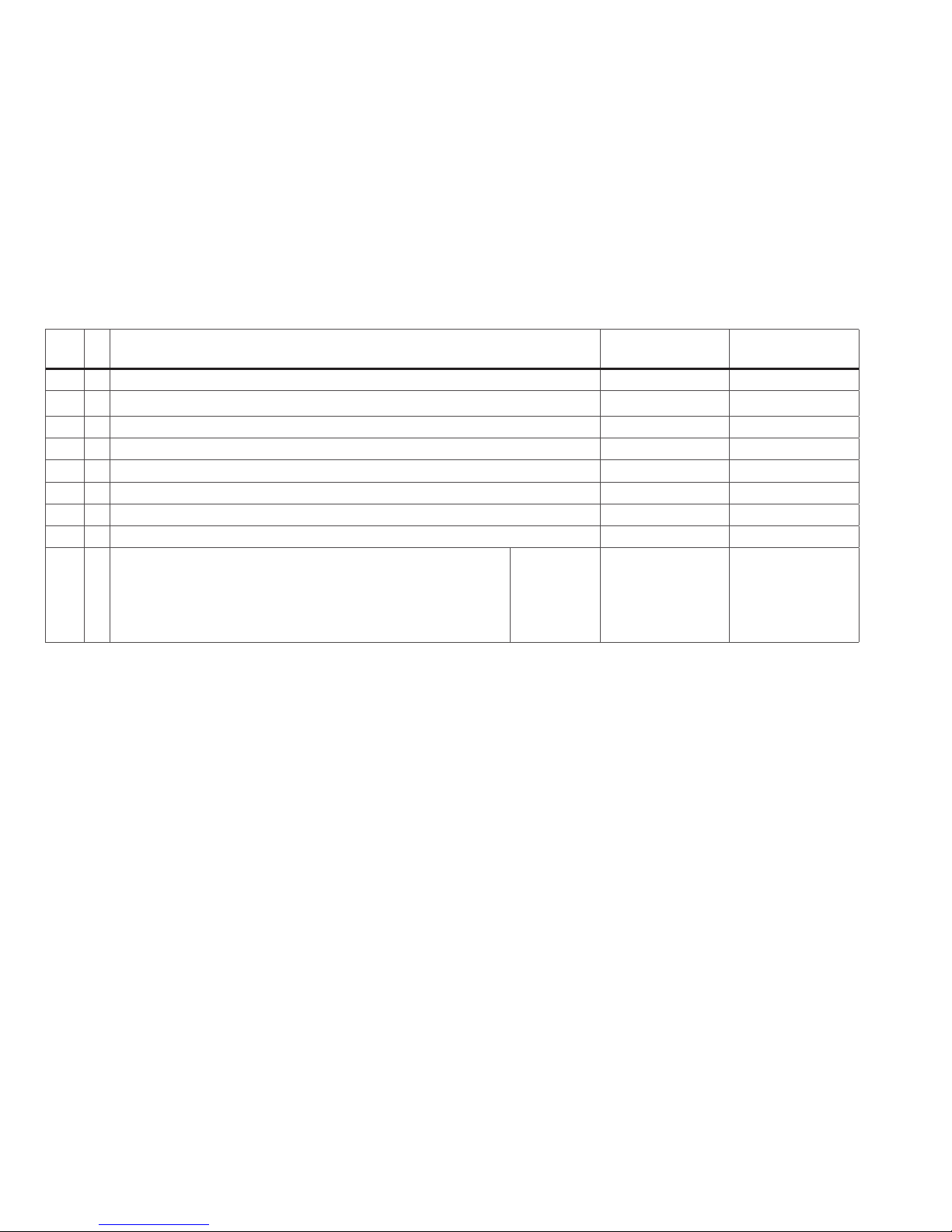
*** Die Werte der gewünschten Einstellungen sind zu addieren!
CV
Bedeutung Wert DCC ab Werk
1 Adresse 1 - 127 3
2
Minimalgeschwindigkeit
0 - 15 4
3 Anfahrverzögerung 0 - 127 8
4 Bremsverzögerung 0 - 127 6
5 Maximalgeschwindigkeit 0 - 255 64
8 Werksreset 8 131
17 Erweiterte Adresse (oberer Teil) CV 29, bit 5 =1 192
18 Erweiterte Adresse (unterer Teil) CV 29, bit 5 =1 0
29
bit 0: Umpolung Fahrtrichtung
bit 1: Anzahl Fahrstufen 14 oder 28/128
bit 2: DCC Betrieb mit Bremsstrecke oder Gleichstrombetrieb
bit 5: Adressumfang 7 bit / 14 bit
Wert
0 / 1
0 / 2
0 / 4
0 / 32
***
0, 1, 2, 3, 4, 5, 6, 7,
32, 34, 35, 36, 37,
38, 39
4
Page 6

6
Technical Features:
• Built-in electronic circuit for operation with a conventional
DC power pack (max. ±12 volts), Trix Systems or NMRA
DCC digital systems.
• Automatic system recognition between digital and analog
operation.
•
Headlights for the locomotive change over with the direction
of travel. They can be turned on and off in digital
operation.
The necessary maintenance that will comes due with normal
operation is described below. Please see your authorized Trix
dealer for repairs or spare parts.
Safety Warnings
•
The feeder track must be equipped to prevent interference
with radio and television reception, when the locomotive is to
be run in conventional operation. The 611 655 interference sup
pression set is to be used for this purpose. The inter-ference
suppression set is not suitable for digital operation.
• This locomotive is to be used only with an operating system
designed for it.
Notes on digital operation:
• This locomotive comes from the factory programmed for
the digital address “03” (DCC). Number of speed levels that
have been set:28 (DCC)
• Information about DCC Operation: The setting done at the
factory does not permit operation with opposite polarity DC
power in the braking block. If you want this characteristic,
you must do without conventional DC power operation
(CV29 / Bit 2 = 0).
• Function:
F0 Headlights
F1 —
F2 Sound effect: Operating sounds
F3 Sound effect: Whistle
F4 Direct control (ABV) on/off
F5 Sound effects: Coal being shoveled
F6 Sound effect: Air pump
F7 —
F8 —
F9 Sound effect: Injector
F10 Sound effect: Blowing off steam
F11 Sound effect: Rocker grate
• Malfunctions resulting from changes to the factory settings
of the locomotive electronics are caused by the operator and
do not give grounds for complaint under our guarantee or
warranty obligations.
No warranty or damage claims shall be accepted in those cases where
parts neither manufactured nor approved by Trix have been installed in
Trix products or where Trix products have been converted in such a way
that the non-Trix parts or the conversion were causal to the defects and/or
damage arising. The burden of presenting evidence and the burden of
proof thereof, that the installation of non-Trix parts or the conversion in or
of Trix products was not causal to the defects and/or damage arising, is
borne by the person and/or company responsible for the installation and/or
conversion, or by the customer.
Page 7
7
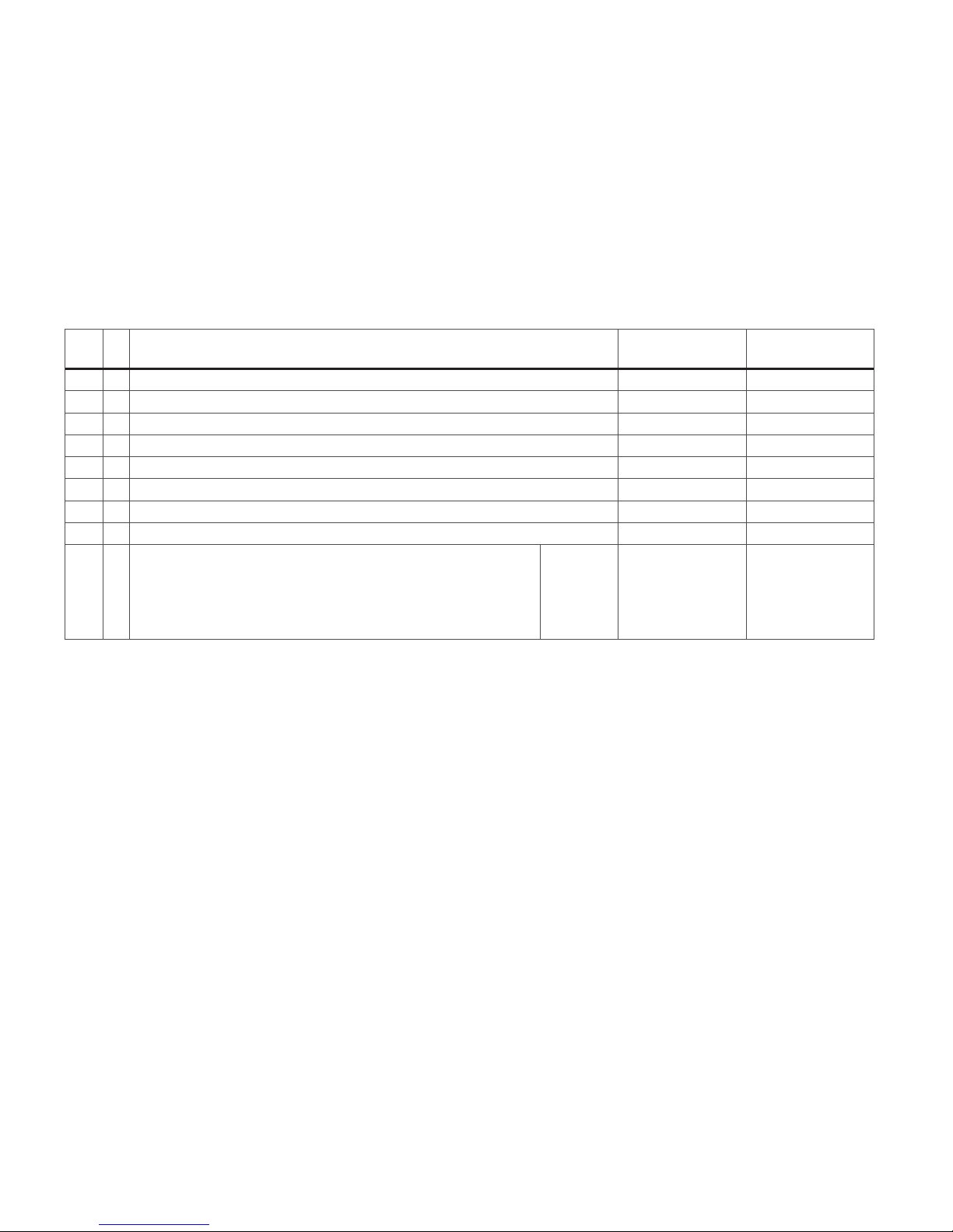
*** The values for the desired settings must be added.
CV
Discription DCC Value
Factory Setting
DCC
1 Adress 1 - 127 3
2 Minimum speed 0 - 15 4
3 Acceleration delay 0 - 127 8
4 Braking delay 0 - 127 6
5 Maximum speed 0 - 255 64
8 Factory Reset 8 131
17 Extended address (upper part) CV 29, bit 5 =1 192
18 Extended address (lower part) CV 29, bit 5 =1 0
29
bit 0: Travel direction polarity reversal
bit 1: number of speed levels 14 or 28/128
bit 2: DCC Operation with braking Block. DC power Operation
bit 5: Adress size 7 bit / 14 bit
Value
0 / 1
0 / 2
0 / 4
0 / 32
***
0, 1, 2, 3, 4, 5, 6, 7,
32, 34, 35, 36, 37,
38, 39
4
Page 8

8
• Fonction:
F0 Fanal
F1 —
F2 Bruitage : Bruit d’exploitation
F3 Bruitage : Sifflet locomotive
F4 Temporisation d’accélération et de freinage
F5 Bruitage : Pelletage du charbon
F6 Bruitage : Compresseur
F7 —
F8 —
F9 Bruitage : Bruitage : Injecteur
F10 Bruitage : Échappement de la vapeur
F11 Bruitage : Boîte à tiroir
•
Les défaillances au niveau du fonctionnement, découlant
de la modification des réglages faits en usine sur le systè
me électronique de la locomotive, sont déclenchées par
l‘opérateur et ne constituent par conséquent aucune raison
de réclamation; elles ne donnent de ce fait aucun droit de
recours en garantie contractuelle ou commerciale.
Tout recours à une garantie commerciale ou contractuelle ou à une
demande de dommages-intérêt est exclu si des pièces non autorisées
par Trix sont intégrées dans les produits Trix et/ou si les produits Trix sont
transformés et que les pièces d’autres fabricants montées ou la transformation constituent la cause des défauts et/ou dommages apparus. C’est à
la personne et/ou la société responsable du montage/ de la transformation
ou au client qu’incombe la charge de prouver que le montage des pièces
d’autres fabricants sur des produits Trix ou la transformation des produits
Trix n’est pas à l’origine des défauts et ou dommages apparus.
Equipement technique:
• Electronique intégrée pour exploitation au choix avec
transformateur-régulateur conventionnel délivrant du courant
continu (max. ±12 volts), Trix Systems
ou avec des systèmes
de conduite digitale conformes aux normes NMRA.
• Reconnaissance automatique du système entre exploitations
numérique et analogique.
• Feux de signalisation s’inversant selon le sens de marche;
feux commutables en exploitation digital.
Les travaux d’entretien dus à un usage normal sont décrits
ci-dessous. Adressez-vous à votre revendeur Trix pour les
réparations et les pièces de rechange.
Remarques importantes sur la sécurité
• Pour l’exploitation de la locomotive en mode conventionnel, la
voie de raccordement doit être déparasitée. A cet effet, utiliser le set de déparasitage réf. 611 655. Le set de déparasitage
ne convient pas pour l’exploitation en mode numérique.
• La locomotive ne peut être mise en service qu’avec un systè
-
me d’exploitation adéquat.
Remarques relatives au fonctionnement en mode digital:
• En usine, c’est l‘adresse «03» (DCC), qui est programmée
pour une exploitation digitale de cette locomotive. Nombre de
crans de marche encodés: 28 (DCC) .
• Remarque concernant l’exploitation DCC: L’exploitation avec
courant continu de polarité inverse dans les sections de
freinage n’est pas possible avec le réglage d’usine. Si cette
propriété est désirée, il faut alors renoncer à l’exploitation
conventionnelle en courant continu (CV29 / bit 2 = 0).
Page 9
9
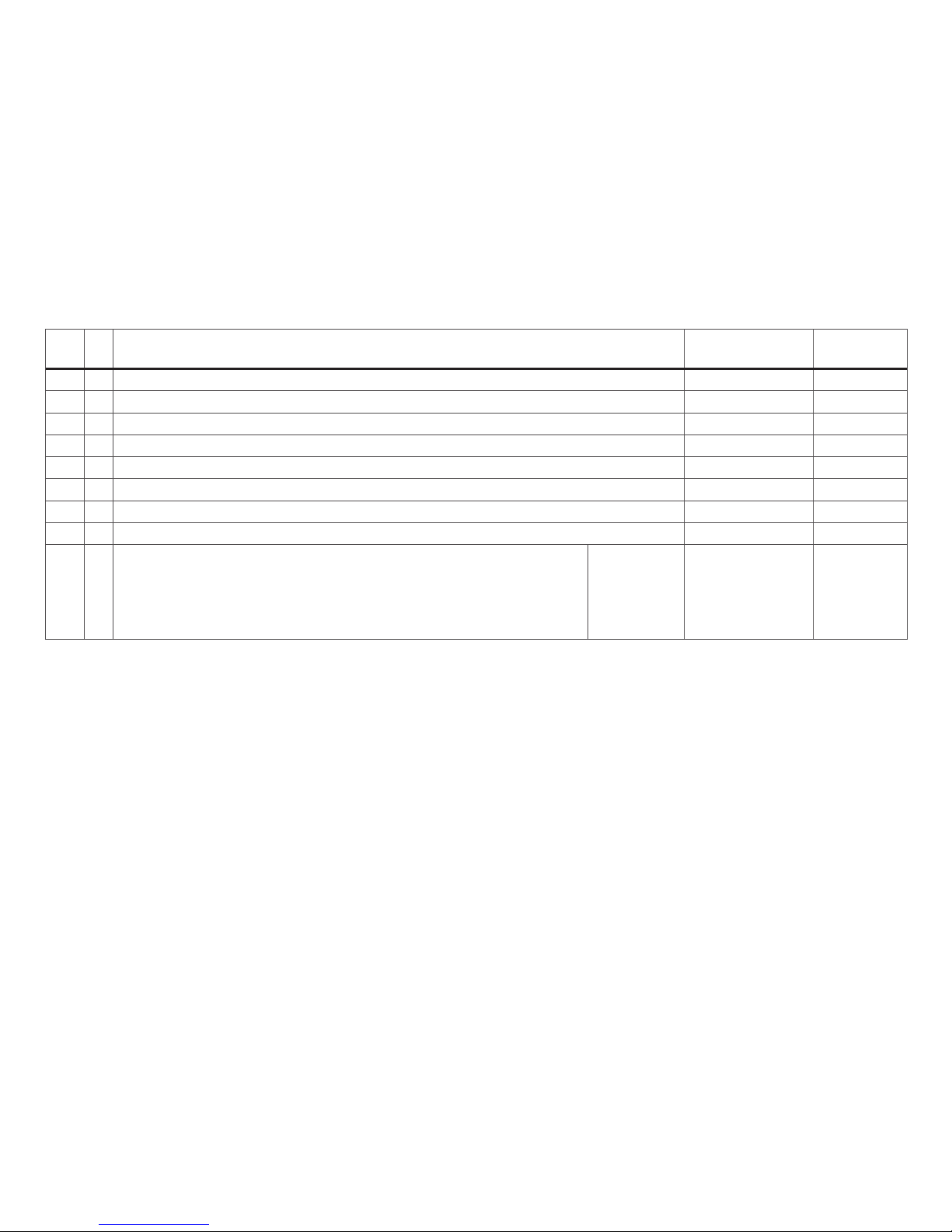
*** Les valeurs des réglages désirés sont à additioner.
CV
Signification Vaieur DCC Valeur Parm. Usine
DCC
1 Adresse 1 - 127 3
2 Vitesse minimale 0 - 15 4
3 Temporisation d‘accélération 0 - 127 8
4 Temporisation de freinage 0 - 127 6
5 Vitesse maximale 0 - 255 64
8 Réinitialisation d’usine 8 131
17 Adresse étendue (partie supérieure) CV 29, bit 5 =1 192
18 Adresse étendue (partie inférieure) CV 29, bit 5 =1 0
29
bit 0: inversion de polarité, sens de marche
bit 1: Nombre de crans de marche 14 ou 28/128
bit 2: Exploitation DCC avec zone de freinage. DCC et courant continu
bit 5: taille d‘adresse 7 bit / 14 bit
Vaieur
0 / 1
0 / 2
0 / 4
0 / 32
***
0, 1, 2, 3, 4, 5, 6, 7,
32, 34, 35, 36, 37,
38, 39
4
Page 10

10
Technische uitvoering:
• Ingebouwde elektronica die het mogelijk maakt om naar keuze met, een conventionele gelijkstroomrijregelaar (max. ±12
Volt), Trix Systems of digitaalsysteem volgens NMRA-norm te
rijden.
• Automatische systeemherkenning tussen digitaal- en ana
-
loogbedrijf.
• Rijrichtingsafhankelijke verlichting is in het digitaalsysteem
schakelbaar.
De bij normaal gebruik noodzakelijke onderhoudspunten worden verderop beschreven. Voor reparaties en onderdelen kunt
zich tot Uw Trix handelaar wenden.
Veiligheidsvoorschriften
• Voor het conventionele bedrijf met de loc dient de aansluitrail te worden ontstoort. Hiervoor dient men de ontstoorset 611 655 te gebruiken. Voor het digitale bedrijf is deze
ontstoor-set niet geschikt.
• De loc mag alleen met een daarvoor bestemd bedrjfssys
-
teem gebruikt worden.
Aanwijzingen voor digitale besturing:
• Vanaf de fabriek is deze loc geprogrammeerd op het digitale
adres “03” (DCC). Ingestelde rijstappen: 28 (DCC)
• Opmerking voor het DCC-bedrijf:
het bedrijf met tegengepoolde gelijkspanning in de afremsectie is met de fabrieksinstelling niet mogelijk. Indien deze
eigenschap wenselijk is, dan moet worden afgezien van het
conventioneel gelijkstroombedrijf (CV29 / bit 2 = 0).
• Functie:
F0 Frontverlichting
F1 —
F2 Geluid: bedrijfsgeluiden
F3 Geluid: fluit
F4 Directe aansturing optrek- afrem vertraging (ABV)
F5 Geluid: kolenscheppen
F6 Geluid: luchtpomp
F7 —
F8 —
F9 Geluid: injecteur
F10 Geluid: stoom afblazen
F11 Geluid: schuivenkast
• Functiestoringen die door wijziging van de fabrieksmatige
instellingen van loc-elektronica veroorzaakt worden, zijn
aan de gebruiker zelf te wijten en derhalve geen gerede
grond voor reclamering op basis van de garantie- en
aansprakelijkheidsaanspraken.
Elke aanspraak op garantie en schadevergoeding is uitgesloten, wanneer in Trix-producten niet door Trix vrijgegeven vreemde onderdelen
ingebouwd en/of Trix-producten omgebouwd worden en de ingebouwde
vreemde onderdelen resp. de ombouw oorzaak van nadien opgetreden
defecten en/of schade was. De aantoonplicht en de bewijslijst daaromtrent, dat de inbouw van vreemde onderdelen in Trix-producten of de
ombouw van Trix-producten niet de oorzaak van opgetreden defecten
en/of schade is geweest, berust bij de voor de inbouw en/of ombouw
verantwoordelijke persoon en/of firma danwel bij de klant.
Page 11

11
*** De waarde van de gewenste instellingen moeten bij elkaar opgeteld worden.
CV
Betekenis Waarde DCC Af fabriek
DCC
1 Adres 1 - 127 3
2 Minimumsnelheid 0 - 15 4
3 Optrekvertraging 0 - 127 8
4 Afremvertraging 0 - 127 6
5 Maximumsnelheid 0 - 255 64
8 Fabrieksinstelling 8 131
17 Uitgebreld adres (bovenste gedeelte) CV 29, bit 5 =1 192
18 Uitgebreld adres (onderste gedeelte) CV 29, bit 5 =1 0
29
bit 0: ompoling rijrichting
bit 1: aantal rijstappen 14 of 28/128
bit 2: DCC-bedrijf met afremtraject.
DCC-en gelijkstroombedrijf
bit 5: adresbereik 7 bit / 14 bit
Waarde
0 / 1
0 / 2
0 / 4
0 / 32
***
0, 1, 2, 3, 4, 5, 6, 7,
32, 34, 35, 36, 37,
38, 39
4
Page 12

12
renunciarse al funcionamiento convencional con corriente
continua (CV29 / Bit 2 = 0)
• Función:
F0 Faros frontales
F1 —
F2 Ruido: ruido de explotación
F3 Ruido del silbido
F4 Control directo (ABV)
F5 Ruido: Cargar carbón con pala
F6 Ruido: Bomba de aire
F7 —
F8 —
F9 Ruido: Inyector
F10 Ruido: Purgar vapor
F11 Ruido: Cámara de vapor
• En el caso de fallos debidos a modificaciones en los ajustes
de fábrica del sistema electrónico de la locomotora se
considerará como único responsable al usuario y, por ello, no
serán motivo de reclamación de derechos de garantía.
Trix non fornisce alcuna garanzia, assicurazione e risarcimento danni in caso
di montaggio sui prodotti Trix di componenti non espressamente approvati dalla
ditta. Trix altresì non risponde in caso di modifiche al prodotto, qualora i difetti e i
danni riscontrati sullo stesso siano stati causati da modifiche non autorizzate o dal
montaggio di componente esterni da lei non approvati. L‘onere della prova che i
componenti montati e le modifiche apportate non sono state la causa del danno o del
difetto, resta a carico del cliente o della persona/ditta che ha effettuato il montaggio
di componenti estranei o che ha apportato modifiche non autorizzate.
Equipamiento técnico:
• Electrónica incorporada para un funcionamiento a discreción
en corriente continua convencional (máx. ±12 V.),
Trix Systems ,
Digital según las normas NMRA.
• Detección automática del sistema entre modo digital y modo
analógico.
• Faros encendidos según el sentido de marcha. En Digital se
pueden encender y apagar.
A continuación están relacionados los trabajos de mantenimiento necesarios para un funcionamiento normal. En
caso de precisar una reparación o piezas de recambio,
rogamos ponerse en contacto con su distribuidor Trix.
Aviso de seguridad
• Para el funcionamiento convencional de la locomotora deben
suprimirse las interferencias en la vía de conexión de la
alimentación. Para ello debe emplearse el set supresor de
interferencias 611 655. El set supresor de interferencias no es
adecuado para el funcionamiento en modo digital.
• La locomotora solamente debe funcionar en un sistema de
corriente propio.
Indicaciones para el funcionamiento digital:
• En esta locomotora viene programada de fábrica la dirección
„01“ (Selectrix) / „03“ (DCC) para el modo digital y con 28
pasos de acceleración (DCC) resp. 31 (Selectrix).
• No es posible el funcionamiento con tensión de corriente
continua de polaridad opuesta en el tramo de frenado en funci
-
onamiento en modo DCC. Si se desea esta característica, debe
Page 13

13
*** ¡Los valores de los ajustes deseados deben sumarse!
CV
Significado
Valor DCC
Preselección
DCC
1 Códigos 1 - 127 3
2 Velocidad minima 0 - 15 4
3 Arranque progresivo 0 - 127 8
4 Frenado progresivo 0 - 127 6
5 Velocidad máxima 0 - 255 64
8 Reset de fábrica 8 131
17 Dirección ampliada (parte superior) CV 29, bit 5 =1 192
18 Dirección ampliada (parte inferior) CV 29, bit 5 =1 0
29
Bit 0:
inversión de la polaridad, sentido de la marcha + luces
Bit 1: pasos de velocidad 14 o 28/128
bit 2: DCC Funciono freno
DCC- y corriente continua
Bit 5: capacidad de códigos 7 bit / 14 bit
Valor
0 / 1
0 / 2
0 / 4
0 / 32
***
0, 1, 2, 3, 4, 5, 6, 7,
32, 34, 35, 36, 37,
38, 39
4
Page 14

14
tal caso rinunciare al funzionamento tradizionale in corrente
continua (CV29 / Bit 2 = 0)
• Funzione:
F0 Illuminazione di testa
F1 —
F2 Rumore: rumori di esercizio
F3 Rumore: Fischio da locomotiva
F4 Comando diretto (ABV) accesa/spenta
F5 Rumore: Spalatura del carbone
F6 Rumore: compressore dell’aria
F7 —
F8 —
F9 Rumore: iniettore
F10 Rumore: scarico del vapore
F11 Rumore: cassetti di distribuzione
• Anomalie derivanti dalla modifica delle impostazioni di
fabbrica dell‘impianto elettronico della locomotiva sono
imputabili all‘utilizzatore e non costituiscono pertanto motivo
di lamentela in merito a richieste di garanzia.
Se excluye todo derecho de garantía, prestación de garantía e indemnización sobre aquellos productos Trix en los que se hubieran montado
piezas ajenas no autorizadas por Trix y/o sobre aquellos productos Trix
que hayan sido modificados cuando la piezas ajenas montadas o la
modificación sean las causas de los desperfectos y/o daños posteriormente surgidos. La persona y/o empresa o el cliente responsable del
montaje o modificación será el responsable de probar y alegar que el
montaje de piezas ajenas o la modificación en/de productos Trix no son
las causas de los desperfectos y/o daños surgidos.
Equipaggiamento tecnico:
• Modulo elettronico incorporato per il funzionamento a scelta
con un tradizionale regolatore di marcia in corrente continua
(max. 12 volt),
Trix Systems
oppure sistemi digitali in base alla
normativa NMRA.
• Riconoscimento automatico del sistema tra funzionamento
digitale ed analogico.
• Illuminazione dipendente dal senso di marcia.Commutabile
nel funzionamento Digital.
Qui di seguito vengono descritte le operazioni di manutenzione che si verificano nel normale esercizio. Per riparazioni
oppure parti di ricambio Vi preghiamo di rivolgerVi al Vostro
rivenditore specializzato Trix.
Avvertenze per la sicurezza
• Per il funzionamento tradizionale della locomotiva il
binario di alimentazione deve essere protetto dai disturbi.
A tale scopo si deve impiegare il corredo antidisturbi
611 655. Tale corredo antidisturbi non è adatto per il
funzionamento Digital.
• Tale locomotiva deve essere impiegata soltanto con un
sistema di funzionamento adeguato per questa.
Istruzioni per la funzione digitale:
• Nel caso di questa locomotiva per il funzionamento digitale
viene programmato dalla fabbrica l’indirizzo „03“ (DCC).
Numero dei livelli di marcia impostati: 28 (DCC) .
• Un funzionamento con tensione continua di polarità invertita
nella sezione di frenatura, in caso di esercizio con DCC, non
è possibile. Se si desidera questa caratteristica, si deve in
Page 15

15
*** I valori delle impostazioni desiderate si devono sommare!
CV
Significato
Valore DCC
Di fabbrica
DCC
1 Indirizzo 1 - 127 3
2 Velocità minima 0 - 15 4
3 Ritardo di avviamento 0 - 127 8
4 Ritardo di frenatura 0 - 127 6
5 Velocità massima 0 - 255 64
8 Ripristino di fabbrica 8 131
17 Indirizzo ampliato (parte superiore) CV 29, bit 5 =1 192
18 Indirizzo ampliato (parte inferiore) CV 29, bit 5 =1 0
29
Bit 0: inversione di polarità senso di marcia+luce
Bit 1: Numero dei livelli di marcia 14 o 28/128
Bit 2: DCC sistemi freni, DCC- e corrente continua
Bit 5: Estensione dell’indirizzo 7 bit / 14 bit
Valore
0 / 1
0 / 2
0 / 4
0 / 32
***
0, 1, 2, 3, 4, 5, 6, 7,
32, 34, 35, 36, 37,
38, 39
4
Page 16

16
Teknisk utrustning:
• Inbyggd elektronik för valfri drift med konventionell likströmskörenhet (max ±12 Volt), Trix Systems
eller Digitalsystem enligt
NMRA-standard.
• Automatisk igenkänning mellan digital- och analog-drift.
• Körriktningsberoende belysning. Kan kopplas in vid digital
drift.
Vid normal användning förekommande underhållsarbeten beskrivs i följande. Kontakta din Trix-handlare för repa
-
rationer eller reservdelar.
Säkerhetsanvisningar
• När den motorförsedda lokdelen ska köras med konventionell
drift måste anlutningsskenan vara avstörd. Till detta använder
man anslutningsgarnityr 611 655 med avstörning och överbelastningsskydd. Avstörningsskyddet får inte användas vid
digital körning.
• Loket får endast köras med ett därtill avsett drift-system.
Anvisningar för digital drift:
• Från tillverkaren har loket programmerats på adress 03“
(DCC). Antal inställda körsteg: 28 (DCC)
• Vid DCC-drift kan man
inte köra med tvåpolig
likspänning på ett bromsavsnitt. Önskar man ändå genomföra en sådan körning, så måste man förlita sig på konventionell likströmsdrift. (CV29 / Bit 2 = 0)
• Funktion:
F0 Frontstrålkastare
F1 —
F2 Ljud: Trafikljud
F3 Ljud: Lokvissla
F4 Direktstyrning (ABV) till/från
F5 Ljud: Kol skyfflas
F6 Ljud: Luftpump
F7 —
F8 —
F9 Ljud: Injektor
F10 Ljud: Ånga släpps ut
F11 Ljud: Slidskåp
• Felfunktioner, som har uppstått genom att ändringar gjorts på
lokelektronikens fabriksinställningar, är orsakade av använ
daren och utgör därför inget reklamationsskäl vid eventuella
garantianspråk.
Varje form av anspråk på garanti och skadestånd är utesluten om delar
används i Trix-produkter som inte har godkänts av Trix och/eller om Trixprodukter har modifierats och de inbyggda främmande delarna resp. modifieringen var upphov till de därefter uppträdande felen och/eller skadorna.
Bevisbördan för att inbyggnaden av främmande delar i eller ombyggnaden
av Trix-produkter inte är upphovet till de uppträdande felen och/eller
skadorna, bär den person och/eller företag resp. kund som är ansvarig för
in- och/eller ombyggnaden.
Page 17

17
CV
Betydelse Värde DCC Fabr.inst.
DCC
1 Adress 1 - 127 3
2 Minfart 0 - 15 4
3 Accelerationsfördröjning 0 - 127 8
4 Bromsfördröjning 0 - 127 6
5 Maxfart 0 - 255 64
8 Återställning till fabrikens 8 131
17 Utvidgad adress (övre del) CV 29, bit 5 =1 192
18 Utvidgad adress (undre del) CV 29, bit 5 =1 0
29
Bit 0: Polvändning körriktning + belysning
Bit 1: Antal körsteg 14 eller 28/128
Bit 2: DCC Driftsystem bromser, DCCoch likström
Bit 5: Adressomfång 7 bit / 14 bit
Värde
0 / 1
0 / 2
0 / 4
0 / 32
***
0, 1, 2, 3, 4, 5, 6, 7,
32, 34, 35, 36, 37,
38, 39
4
*** De önskade inställningarnas värden ska adderas/läggas samman!
Page 18

18
Teknisk udstyr:
• Indbygget elektronik til valgfri drift med konventionelt
jævnstrømskøreudstyr (maks. ±12 volt), Trix Systems eller
Digitalsystemer efter NMRA-norm.
•
Automatisk systemgenkendelse mellem digital- og analogdrift
.
• Belysning afhængig af køreretning. Kan tændes og slukkes
til digitaldrift.
De ved normal drift forekommende vedligeholdelsesarbejder
er efterfølgende beskrevet. Angående reparationer eller
reservedele bedes De henvende Dem til Deres Trix-forhandler.
Vink om sikkerhed
• Ved konventionel drift af lokomotivet skal tilslutningssporet
støjdæmpes. Dertil skal anvendes støjdæmpningssættet
611 655. Støjdæmpningssættet er ikke egnet til digital drift.
• Lokomotivet må kun bruges med et driftssystem, der er
beregnet dertil.
Henvisninger til digitaldrift:
•
Fra fabrikken er adressen “03” (DCC) programmeret til digitaldrift på dette lokomotiv. Indstillet antal køretrin: 28 (DCC).
• Det er ved DCC-drift ikke muligt at anvende drift med
modpolet jævnspænding i bremseafsnittet. Hvis denne
egenskab ønskes, må der gives afkald på den konventionelle jævnstrømsdrift. (CV29 / Bit 2 = 0)
• Funktion:
F0 Frontbelysning
F1 —
F2 Lyd: Driftslyd
F3 Lyd: Lokomotivfløjte
F4 Direkte styring (ABV) til/fra
F5 Lyd: Skovling af kul
F6 Lyd: Luftpumpe
F7 —
F8 —
F9 Lyd: Injektor
F10 Lyd: Dampudledning
F11 Lyd: Glidekasse
• Fejlfunktioner, der forårsages af ændringer i lokomotivets
fabriksindstillede elektronik, er forårsaget af brugeren selv
og kan derfor ikke gøres til genstand for reklamation under
garantien.
Ethvert garanti-, mangelsansvars- og skadeserstatningskrav er udelukket, hvis der indbygges fremmeddele i Trixprodukter, der ikke er frigivet
dertil af Trix og/eller hvis Trixprodukter bygges om og de indbyggede
fremmeddele hhv. ombygningen var årsag til sådanne opståede mangler
og/eller skader. Det påhviler kunden hhv. den person og/eller det firma,
der er ansvarlig for ind- og/eller ombygningen, at påvise hhv. bevise, at
indbygningen af fremmeddele i, eller ombygningen af Trixprodukter ikke
var årsag til opståede mangler og/eller skader.
Page 19

19
CV
Betydning Værdi DCC Frau fabrikken
DCC
1 Adress 1 - 127 3
2 Minimalhastighed 0 - 15 4
3 Opstartforsinkelse 0 - 127 8
4
Bremseforsinkelse
0 - 127 6
5 Maksimalhastighed 0 - 255 64
8 Fabriksnulstilling 8 131
17 Udvidet adresse (Øverste del) CV 29, bit 5 =1 192
18 Udvidet adresse (Nederste del) CV 29, bit 5 =1 0
29
Bit 0: Ompoling kørselsretning + lys
Bit 1: Antal køretrin 14 eller 28/128
Bit 2: DCC driftssystemer med bremse
DCC -selectrix og Jævnstrøm
Bit 5: Adresseomfang 7 bit / 14 bit
Værdi
0 / 1
0 / 2
0 / 4
0 / 32
***
0, 1, 2, 3, 4, 5, 6, 7,
32, 34, 35, 36, 37,
38, 39
4
*** Værdierne for de ønskede indstillinger skal lægges sammen!
Page 20

20
Kolbenstangenschutzrohr einsetzen
How to install the cylinder rot protector
Insérer le tube de protection de la lige de piston
Beschermbuis cilinderstang plaatsen
Colocar el tubo protector de la biela
Installazione del tubetto di protezione per
l’asta dello stantuffo Kolvstångsskyddsröret monteras
Cylinderstang-beskyttelsesør indsættes
Radius > 500 mm (19` 2/3``)
Kupplung austauschen
Exchanging the close coupler
Remplacement de l’attelage court
Omwisselen van de kortkoppeling
Enganches cortos
Sostituzione del gancio corto
Utbyte av kortkoppel
Udskiftning af kortkoblingen
NEM 362
Page 21

21
Gehäuse abnehmen
Removing the body
Enlever le boîtier
Kap afnemen
Retirar la carcasa
Smontare il mantello
Kåpan tas av
Overdel tages af
Page 22

22
Gehäuse aufsetzen
Put the body back on
Mettre le boîtier en place
Huis plaatsen
Poner la carcasa
Montare la sovrastruttura
Sätt på kåpan
Huset (overdel) sættes på
Page 23

23
Haftreifen auswechseln
Changing traction tires
Changer les bandages d’adhérence
Antislipbanden vervangen
Cambio de los aros de adherencia
Sostituzione delle cerchiature di aderenza
Slirskydd byts
Friktionsringe udskiftes
7153
2,5 mm
Motor-Bürsten auswechseln
Changing motor brushes
Changer les balais du moteur
Koolborstels vervangen
Cambio de las escobillas
Sostituzione delle spazzole del motore
Motorborstar byts
Motorkul udskiftes
��
��
Page 24

24
Schmierung nach etwa 40 Betriebsstunden
Wichtige Hinweise zum Ölen der Motorlager:
• Nur sparsam ölen (max. 1 Tropfen). Zuviel Öl führt häufig zum
Verschmieren der Kollektoren und damit zur Beschädigung
des Ankers.
• Nach dem Aufbringen des Öltropfens auf das Motor-Lager
den Anker bewegen. Anschließend überschüssiges Öl mit
einem trockenen Tuch entfernen.
• Lokomotive nach Möglichkeit nicht längere Zeit liegend
lagern, da es sonst möglich ist, dass Lageröl zum Kollektor
gelangt und ihn beschädigt.
66625
Lubrication after approximately 40 hours of operation
Important Information about Oiling the Motor Bearings:
• Oil sparingly (max. 1 drop). Too much oil frequently causes the
commutator to become dirty and thereby leads to damage to
the armature.
• After you have placed a drop of oil on the motor bearings,
move the armature back and forth a little. Now remove the
excess oil with a dry cloth.
• If possible, do not store the locomotive for long´periods of
time on its side, because it is possible that the bearing oil will
get into the commutator and damage it.
Page 25

25
Graissage après environ 40 heures de marche
Remarque importante au sujet de la lubrification des
paliers du moteur:
• Lubrifiez en très petite quantité (1 goutte max.). Trop d‘huile
entraîne souvent l‘encrassement du collecteur et à des
dommages à l‘induit.
• Une fois la goutte d‘huile déposée sur le palier de moteur,
faites tourner l‘induit. Ensuite, essuyez le surplus d‘huile à
l‘aide d‘un chiffon sec.
• Si possible, ne pas laisser la locomotive couchée trop longt
emps car il peut arriver que l‘huile emmagasinée dans les
paliers parvienne dans l‘induit et l‘endommage.
Smering na ca. 40 bedrijfsuren
Belangrijke opmerking voor het oliën van het motorlager:
• Slechts spaarzaam oliën (max. 1 druppel). Te veel olie leidt
vaak tot versmeren van de collector en daarmee tot beschadiging van het anker.
• Na het aanbrengen van de oliedruppel op het motorlager
het anker ronddraaien. Aansluitend met een droge doek de
overvloedige olie verwijderen.
• Locomotief indien mogelijk niet langere tijd, liggend op de
zijkant, opslaan, aangezien het dan mogelijk is dat de olie van
het motorlager de collector bereikt en deze beschadigt.
!
66625
66625
Page 26

26
Engrase a las 40 horas de funcionamiento
Indicaciones importantes acerca del engrase de los
cojinetes del motor:
• Engrasar poco (máx. 1 gota). Demasiado aceite ensucia el
colector y llega a dañar el rotor.
• Una vez colocada la gota de aceite, mover el rotor. A continu
-
ación quitar el aceite sobrante con un paño seco.
• No guardar las locomotoras tumbadas durante mucho tiem
-
po. Es posible que el aceite llegue hasta el colector y lo dañe.
66625
Lubrificazione dopo circa 40 ore di funzionamento
Importanti avvertenze per la lubrificazione dei cuscinetti del motore:
• Si lubrifichi soltanto con parsimonia (al max. 1 goccia). Troppo olio conduce spesso a un insudiciamento del collettore e
di conseguenza al danneggiamento del rotore.
• Dopo l’applicazione della goccia di olio ai cuscinetti del
motore, si faccia muovere il rotore. Al termine, si elimini l’olio
in eccedenza con un panno asciutto.
• A seconda delle possibilità, non si lasci giacente la locomoti
va per un tempo alquanto lungo, poiché altrimenti è possibile
che l’olio dei cuscinetti arrivi sul collettore e lo danneggi.
Page 27

27
Smörjning efter ca. 40 driftstimmar
Viktiga råd till smörjning av motorlagren:
• Smörj endast sparsamt (max 1 droppe). För mycket olja
leder till nedsmutsning av kollektorerna och därmed skadas
ankaret.
• Snurra ankaret när oljedroppen har placerats på motorlagret.
Torka bort överflödig olja med en torr trasa.
• Loket bör inte förvaras liggande under längre tid, eftersom i
så fall lagerolja kan hamna i kollektorn och skada denna.
Smøring efter ca. 40 driftstimer
Vigtige henvisninger vedr. smøring af motorleje:
• Giv kun lidt olie (maks. 1 dråbe). For meget olie fører ofte til
indsmøring af kollektorerne og dermed til beskadigelse af
ankeret.
• Efter anbringelse af oliedråben på motorlejet skal ankeret
bevæges. Til slut fjernes overskydendeolie med en tør klud.
• Hvis det er muligt, skal det undgås at opbevare lokomotiver i
liggende stilling i længere tid, ellers kan det ske, at lejeolien
kommer ind i kollektoren og beskadiger den.
!
66625
66625
Page 28

28
Schleifer auswechseln
Changing the pickup shoe
Changer le frotteur
Vervangen van het sleepcontact
Cambio del patín toma-corriente
Sostituzione del pattino
Byt släpsko
Udskiftning af slæbesko
Glühlampen auswechseln
Changing light bulbs
Changer les ampoules
Gloeilamp vervangen
Sustituir la bombilla
Cambiare la lampadina
Glödlampor byts
Elpærer skiftes
Page 29

29
66
59
58
45
73
46
83
84
42
48
49
75
69
65
65
65
65
67
67
60
60
60
60
70
69
66
47
82
57
52
84
69
58
46
44
45
68
68
51
64
65
65
67
61
70
69
21
20
66
62
63
52
69
66
26
27
76
74
58
55
56
53
68
68
78
71
77
67
60
60
80
70
70
69
3
79
81
35
55
72
43
54
69
58
36
34
55
54
33
32
31
28
29
31
33
42
50
41
37
40
40
9
8
7
30
13
15
69
39
36
38
25
22
18
11
10
7
2
3
7
17
16
20
16
21
5
22
1
4
3
3
12
13
14
19
24
23
18
17
6
Details der Darstellung
können von dem Modell
abweichen
Page 30

30
1 Aufbau 124 458
mit
2 Führerhaus 124 561
3 Glasteile 123 387
4 Pfeife 448 480
5 Dach 448 850
6 Laterne 460 330
7 Senkschraube 786 790
8 Wasserkasten links 104 065
9 Umlauf links 124 563
10 Wasserkasten rechts 104 064
11 Umlauf rechts 124 562
12 Schmierpumpe 449 070
13 Tritt links 448 520
Tritt rechts 448 510
14 Luftpumpe 448 530
15 Halter 448 710
16 Laterne 460 330
17 Leiter links 448 920
Leiter rechts 448 910
18 Leiter 450 580
19 Pufferbohle 124 564
20 Puffer vorne 761 720
21 Puffer hinten 761 710
22 Zylinderansatzschraube 753 140
23 Stützblech 210 394
24 Lüfteraufsatz 448 870
25 Domdeckel 449 100
26 Decoder / Steckerplatte 124 569
27 Leiterplatte Schnittstelle 611 626
28 Feldmagnet 389 000
29 Anker 386 820
30 Motorschild 386 940
31 Motorbürsten 601 460
32 Lötfahne 231 470
33 Zylinderschraube 785 140
34 Trägerplatte 123 701
35 Lautsprecher 100 622
36 Glühlampe 610 080
37 Abdeckung vorn 460 270
38 Steckfassung 624 510
39 Abdeckung hinten 460 280
40 Laterne 460 340
Page 31

31
41 Abdeckung 445 790
42 Griffstange 445 810
43 Abdampfrohr 445 780
44 Kupplungsdeichsel vorne 445 750
45 Kupplung 7 203
46 Schaltschieberfeder 7 194
47 Traggestell vorne 124 568
48 Zylinder vorne links 124 566
49 Gestänge vorne links 215 283
50 Zylinder vorne rechts 124 567
51 Gestänge vorne rechts 215 272
52 Kolbenstangenschutzrohr 445 900
53 Isolierstück vorne 445 910
54 Isolierscheibe 722 240
55 Zylinderschraube 750 200
56 Lötfahne 446 120
57 Verbindungsstange 445 710
58 Druckfeder 214 330
59 Treibradsatz mit Haftreifen 124 803
60 Haftreifen 7 153
61 Treibradsatz 124 799
62 Treibradsatz 124 801
63 Treibradsatz 124 802
64 Bremsattrappe vorne 490 000
65 Senkschraube 756 100
66 Distanzring 206 262
67 Sechskantmutter 499 830
68 Kuppelstange 215 456
69 Zylinderansatzschraube 499 840
70 Zylinderansatzschraube 499 850
71 Treibgestell hinten 445 460
72 Abdeckung 445 490
73 Kupplungsdeichsel hinten 445 720
74 Zylinder hinten links 446 140
75 Gestänge hinten links 215 287
76 Zylinder hinten rechts 446 130
77 Gestänge hinten rechts 215 289
78 Isolierstück hinten 446 190
79 Treibradsatz mit Haftreifen 124 798
80 Treibradsatz 124 799
81 Treibradsatz 124 801
82 Treibradsatz mit Haftreifen 124 803
83 Bremsattrappe hinten 445 730
84 Schleifer 486 780
Page 32

Änderungen vorbehalten
© by Trix GmbH & Co. KG
Trix Modelleisenbahn GmbH & Co. KG
Stuttgarter Str. 55-57
73033 Göppingen
www.trix.de
121209/0508/HaEf
This device complies with Part 15 of the FCC Rules.
Operation is subject to the following two conditions:
(1) This device may not cause harmful interference, and
(2) this device must accept any interference received, including
interference that may cause undesired operation.
 Loading...