

Page 1
Modell des Elektro-Schnelltriebwagen BR 403
22379
F
D
GB
USA
NL
Page 2

2
Page 3

3
Inhaltsverzeichnis: Seite
Informationen zum Vorbild 4
Hinweise zur Inbetriebnahme 6
Sicherheitshinweise 8
Wichtige Hinweise 8
Multiprotokollbetrieb 8
Schaltbare Funktionen 11
Parameter/Register 12
Wartung und Instandhaltung 28
Ersatzteile 32
Table of Contents: Page
Information about the prototype 4
Notes about using this model for the first time 6
Safety Notes 13
Important Notes 13
Multi-Protocol Operation 13
Controllable Functions 16
Parameter/Register 17
Service and maintenance 28
Spare Parts 32
Sommaire : Page
Informations concernant la locomotive réelle 5
Indications relatives à la mise en service 6
Remarques importantes sur la sécurité 18
Information importante 18
Mode multiprotocole 18
Fonctions commutables 21
Paramètre/Registre 22
Entretien et maintien 28
Pièces de rechange 32
Inhoudsopgave: Pagina
Informatie van het voorbeeld 5
Opmerking voor de ingebruikname 6
Veiligheidsvoorschriften 23
Belangrijke aanwijzing 23
Multiprotocolbedrijf 23
Schakelbare functies 26
Parameter/Register 27
Onderhoud en handhaving 28
Onderdelen 32
Page 4

4
Information about the Prototype
The railroad allocated a considerable sum of money for
equipment and features for the class 403 powered rail car
train that was supposed to replace the diesel powered
class 601 Trans Europe Express units. This was done to link
top-of-the-line technology with comfort. Three sleek racers
were placed into service one after the other starting in 1974.
The TEE level of comfort was of course obligatory on these
trains: The 403 only had first class seating in compartments
and open seating areas, air conditioning, folding-sliding
doors, a dining area, and a galley. An absolute highlight: a
train secretary‘s compartment as well as a telephone booth.
The engineers were faced with the challenge to design the
car bodies with extremely lightweight construction – in contrast to classic car construction with steel, the underbody,
the body frame, the roof, side and end walls were mostly
made of aluminum alloys. This paid off: With only a 16 metric
ton axle load and thanks to all-wheel drive, this express
powered rail car train accelerated in 100 seconds from zero
to 200 km/h / 125 mph. As a rule the train ran at 160 km/h /
100 mph and consisted of two powered end cars (class 403),
an intermediate car with an open seating area (class 404.0),
and an intermediate car with a dining area and a galley
(class 404.1).
As “all-around-talent“ the 403 was also suitable for operation in Austria and Switzerland. The pantographs with
narrow contact wipers required for operation in Switzerland
could be installed on the roofs of the powered end cars.
Informationen zum Vorbild
Für den Triebzug der Baureihe 403, der den dieselgetriebenen Trans Europ Express BR 601 ablösen sollte,
ließ sich die Bahn die Ausstattung einiges kosten, um
Spitzentechnik mit Komfort zu verknüpfen. Drei schnittige
Schienenflitzer kamen nacheinander ab 1974 zum Einsatz.
Der TEE-Komfortstatus war dabei natürlich Pflicht: Im 403
gab es ausschließlich Erste-Klasse-Sitzplätze in Abteilen
und Großräumen, eine Klimaanlage gehörte ebenso zur
Ausstattung wie Schwenkschiebetüren, ein Speiseraum und
eine Küche. Absolutes Highlight: ein Zugsekretariat sowie
eine Telefonzelle.
Die Konstrukteure standen vor der Herausforderung,
die Wagenkästen in einer extremen Leichtbauweise zu
konzipieren – im Gegensatz zum klassischen Wagenbau
mit Stahl entstanden das Untergestell, das Kastengerippe,
die Dach-, Seiten- und Stirnwandbleche zum größten Teil
aus Aluminiumlegierungen. Das zahlte sich aus: Mit nur
16 t Achslast und dank Allachsantrieb beschleunigte der
Schnelltriebzug in 100 Sekunden von null auf 200 km/h. Der
Zug fuhr in der Regel meist mit 160 km/h und bestand aus je
zwei Triebköpfen (BR 403), einem Mittelwagen mit Großraum
(BR 404.0) sowie einem Mittelwagen mit Speiseraum und
Küche (BR 404.1).
Als „Allroundtalent“ war der 403 auch für den Betrieb in Österreich und in der Schweiz geeignet. Auf den Dächern der
Endtriebwagen konnte ein für den Verkehr in der Schweiz
benötigter Stromabnehmer mit schmalem Schleifstück
aufgebaut werden.
Page 5

5
Informatie van het voorbeld
Het treinstel van de serie 403, die de dieseltrein Trans
Europe Express serie 601 moest aflossen, mocht wat kosten
van de spoorwegen. Toptechniek moest namelijk gekoppeld
worden aan comfort. Vanaf 1974 werden één voor één drie
elegante, snelle railvoertuigen ingezet. De comfortstatus
van de TEE was daarbij natuurlijk onaantastbaar: de 403 beschikte uitsluitend over eerste klas zitplaatsen in coupés en
open afdelingen. Verder was het treinstel voorzien van een
klimaatinstallatie, draai/schuifdeuren, een restauratie en
een keuken. De absolute highlights waren een treinsecretariaat en een telefooncel.
De ingenieurs stonden voor de uitdaging om rijtuigbakken
in een zeer lichte constructie te ontwerpen. In tegenstelling tot bij de klassieke rijtuigbouw met staal werden het
onderstel, het bakgeraamte en de dak-, zij- en kopwanden
grotendeels van aluminiumlegeringen vervaardigd. Dat
was de moeite waard: Met een asbelasting van slechts 16
ton en dankzij de Allachs-aandrijving trok het treinstel in
100 seconden op van nul tot 200 kilometer per uur. De trein
reed over het algemeen 160 kilometer per uur en bestond uit
twee motorwagens (serie 403), een tussenrijtuig met open
afdeling (serie 404.0) en een tussenrijtuig met restauratie en
keuken (serie 404.1).
Als „allround talent“ was de 403 ook geschikt voor de dienst
in Oostenrijk en Zwitserland. Op de daken van de eindmotorwagen kon een voor het verkeer in Zwitserland benodigde
stroomafnemer met smal sleepstuk worden gemonteerd.
Informations concernant la locomotive réelle
Pour la rame automotrice de la Série 403, qui devait prendre
le relais du Trans-Europ-Express BR 601 actionné par une
locomotive diesel, la compagnie de chemin de fer ne recula
devant aucune dépense, en matière d’équipement, pour associer la technique de pointe au confort. Trois bolides des voies
furent mis en œuvre, l’un après l’autre, à partir de 1974. Le
niveau de confort associé aux TEE devait naturellement être
pris en compte : dans la 403, il y eut exclusivement des places
assises de première classe, dans des compartiments et dans
des wagons à couloir central. Une climatisation faisait autant
partie de l’équipement que des portes coulissantes et louvoyantes, un local de jeu et une cuisine. Fait saillant absolu :
un secrétariat à disposition dans le train, ainsi qu’une cabine
téléphonique. Les ingénieurs d’étude était confrontés au défi
d’avoir à concevoir les caisses des wagons en une forme de
construction extrêmement légère – contrairement au mode
de construction classique des wagons en acier, le châssis,
l’ossature de caisse, les tôles de toit, les tôles latérales et des
abouts étaient en grande partie en alliages d’aluminium. Cela
a été payant : avec uniquement 16 t de charge par essieu et
grâce à un entraînement par tous les essieux, le turbotrain à
grande vitesse accéléra de zéro à 200 km/h, en 100 secondes
seulement. Le train circulait la plupart du temps à la vitesse
de 160 km/h et était composé de deux véhicules à moteur
(BR 403), d’un wagon intermédiaire avec couloir central (BR
404.0), ainsi que d’un wagon intermédiaire avec salle à manger et cuisine (BR 404.1). En tant que doté de talents multiples,
le 403 était également adapté à une exploitation en Autriche
et en Suisse. Sur les toits des rames automotrices de queue,
il a été possible de construire une prise de courant requise
pour la circulation en Suisse, avec un frotteur étroit.
Page 6
6
Page 7
7
Page 8

8
Sicherheitshinweise
• Die Lok darf nur mit einem dafür bestimmten Betriebssystem eingesetzt werden.
• Analog max. 15 Volt =, digital max. 22 Volt ~.
• Die Lok darf nur aus einer Leistungsquelle versorgt
werden.
• Beachten Sie unbedingt die Sicherheitshinweise in der
Bedienungsanleitung zu Ihrem Betriebssystem.
• Für den konventionellen Betrieb der Lok muss das Anschlussgleis entstört werden. Dazu ist das Entstörset
611 655 zu verwenden. Für Digitalbetrieb ist das Entstörset nicht geeignet.
• ACHTUNG! Funktionsbedingte scharfe Kanten und Spitzen.
• Setzen Sie das Modell keiner direkten Sonneneinstrahlung, starken Temperaturschwankungen oder hoher
Luftfeuchtigkeit aus.
• Verbaute LED`s entsprechen der Laserklasse 1 nach
Norm EN 60825-1.
Wichtige Hinweise
• Die Bedienungsanleitung und die Verpackung sind
Bestandteile des Produktes und müssen deshalb aufbewahrt sowie bei Weitergabe des Produktes mitgegeben
werden.
• Für Reparaturen oder Ersatzteile wenden Sie sich bitte an
Ihren Trix-Fachhändler.
• Gewährleistung und Garantie gemäß der beiliegenden
Garantieurkunde.
• Entsorgung: www.maerklin.com/en/imprint.html
• Der volle Funktionsumfang ist nur unter Trix Systems,
DCC und unter mfx verfügbar.
• Eingebaute, fahrtrichtungsabhängige Stirnbeleuchtung.
Im Digitalbetrieb schaltbar.
• Befahrbarer Mindestradius 360 mm.
Multiprotokollbetrieb
Analogbetrieb
Der Decoder kann auch auf analogen Anlagen oder Gleisabschnitten betrieben werden. Der Decoder erkennt die
analoge Gleichspannung (DC) automatisch und passt sich
der analogen Gleisspannung an. Es sind alle Funktionen,
die unter mfx oder DCC für den Analogbetrieb eingestellt
wurden aktiv (siehe Digitalbetrieb).
Digitalbetrieb
Der Decoder ist ein Multiprotokolldecoder. Der Decoder
kann unter folgenden Digital-Protokollen eingesetzt werden:
mfx oder DCC.
Das Digital-Protokoll mit den meisten Möglichkeiten ist das
höchstwertige Digital-Protokoll. Die Reihenfolge der DigitalProtokolle ist in der Wertung fallend:
Priorität 1: mfx
Priorität 2: DCC
Priorität 3: DC
Hinweis: Werden zwei oder mehrere Digital-Protokolle am
Gleis erkannt, übernimmt der Decoder automatisch das
höchstwertige Digital-Protokoll; z.B. wird mfx & DCC erkannt
wird das mfx-Digital-Protokoll vom Decoder übernommen.
Page 9

9
Hinweis: Beachten Sie, dass nicht alle Funktionen in allen
Digital-Protokollen möglich sind. Unter mfx und DCC können
einige Einstellungen von Funktionen, welche im AnalogBetrieb wirksam sein sollen, vorgenommen werden.
Hinweise zum Digitalbetrieb
• Die genaue Vorgehensweise zum Einstellen der diversen
Parameter entnehmen Sie bitte der Bedienungsanleitung
Ihrer Mehrzug-Zentrale.
• Die ab Werk eingestellten Werte sind für mfx gewählt, so
dass ein bestmöglichstes Fahrverhalten gewährleistet ist.
Für andere Betriebssysteme müssen gegebenenfalls
Anpassungen getätigt werden.
• Der Betrieb mit gegenpoliger Gleichspannung im
Bremsabschnitt ist mit der werkseitigen Einstellung
nicht möglich. Ist diese Eigenschaft gewünscht, so muss
auf den konventionellen Gleichstrombetrieb verzichtet
werden (CV 29/Bit 2 = 0).
mfx-Protokoll
Adressierung
• Keine Adresse erforderlich, jeder Decoder erhält eine
einmalige und eindeutige Kennung (UID).
• Der Decoder meldet sich an einer Central Station oder
Mobile Station mit seiner UID automatisch an.
• Name ab Werk: 403 003-7 LHAE
Programmierung
• Die Eigenschaften können über die grafische Oberfläche
der Central Station bzw. teilweise auch mit der Mobile
Station programmiert werden.
• Es können alle Configuration Variablen (CV) mehrfach
gelesen und programmiert werden.
• Die Programmierung kann entweder auf dem Haupt- oder
dem Programmiergleis erfolgen.
• Die Defaulteinstellungen (Werkseinstellungen) können
wieder hergestellt werden.
• Funktionsmapping: Funktionen können mit Hilfe der
Central Station 60212 (eingeschränkt) und mit der Central
Station 60213/60214/60215 beliebigen Funktionstasten
zugeordnet werden (siehe Hilfe in der Central Station).
Page 10

10
DCC-Protokoll
Adressierung
• Mögliche Adressen: Kurze, lange und Traktionsadresse
• Adressbereich:
1 – 127 (kurze Adresse, Traktionsadresse)
1 – 10239 (lange Adresse)
• Jede Adresse ist manuell programmierbar.
• Kurze oder lange Adresse wird über die CVs ausgewählt.
• Eine angewandte Traktionsadresse deaktiviert die
Standard-Adresse.
Programmierung
• Die Eigenschaften können über die Configurations Variablen (CV) mehrfach geändert werden.
• Die CV-Nummer und die CV-Werte werden direkt eingegeben.
• Die CVs können mehrfach gelesen und programmiert
werden (Programmierung auf dem Programmiergleis).
• Die CVs können beliebig programmiert werden. PoM
(Programmierung auf dem Hauptgleis PoM) ist nur bei
den in der CV-Tabelle gekennzeichneten CV möglich.
PoM muss von Ihrer Zentrale unterstützt werden (siehe
Bedienungsanleitung ihres Gerätes).
• Die Defaulteinstellungen (Werkseinstellungen) können
wieder hergestellt werden.
• 14 bzw. 28/126 Fahrstufen einstellbar.
• Alle Funktionen können entsprechend dem Funktionsmapping geschaltet werden.
• Weitere Information, siehe CV-Tabelle DCC-Protokoll.
Es wird empfohlen, die Programmierungen grundsätzlich auf
dem Programmiergleis vorzunehmen.
Logische Funktionen
Anfahr-/Bremsverzögerung
• Die Beschleunigungs- und Bremszeit können getrennt
von einander eingestellt werden.
• Die logische Funktionsabschaltung ABV kann über das
Funktionsmapping auf jede beliebige Funktionstaste
gelegt werden.
Page 11
11
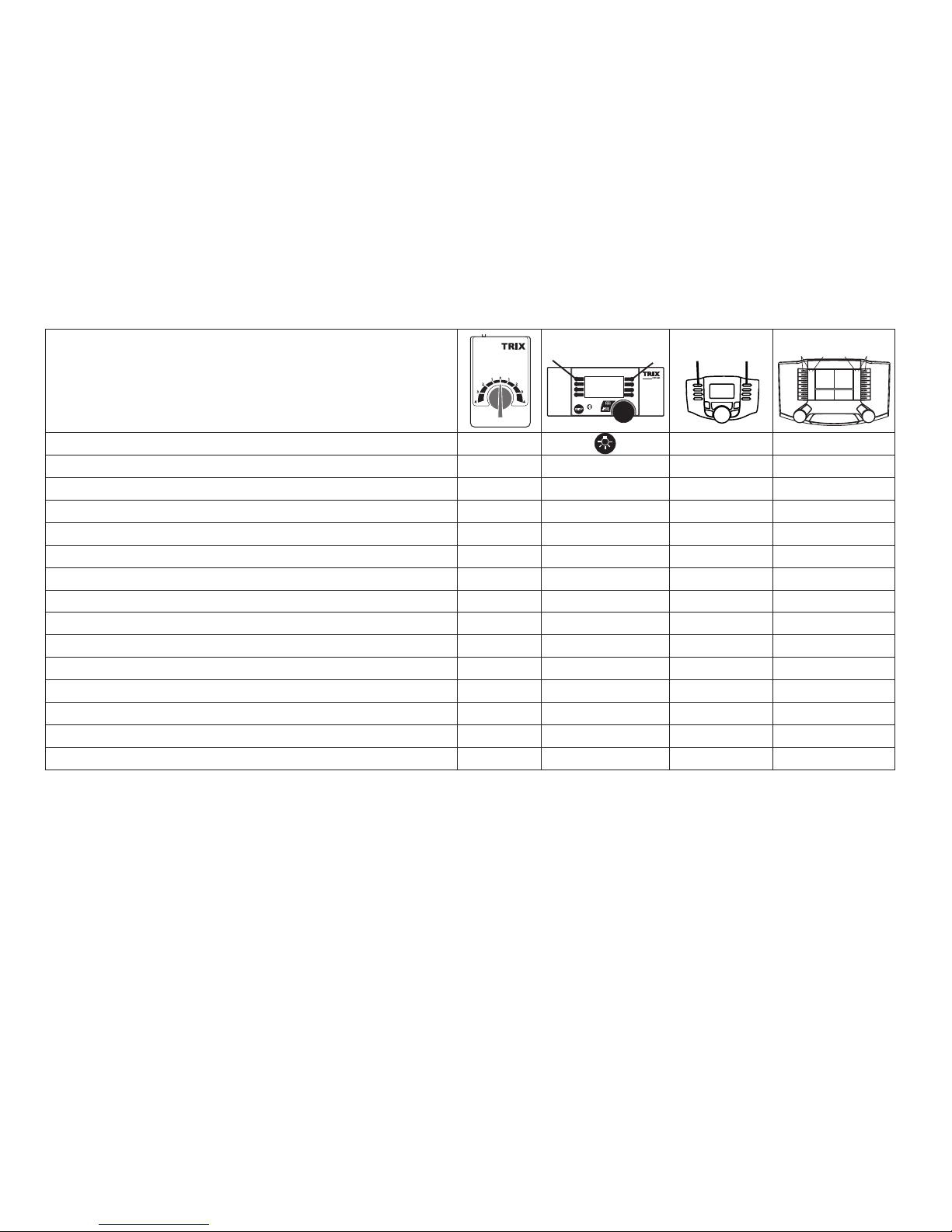
Schaltbare Funktionen
Spitzensignal an
Funktion f0 Funktion f0
Geräusch: Pantograph — Funktion 1 Funktion f1 Funktion f1
Betriebsgeräusch — Funktion 2 Funktion f2 Funktion f2
Geräusch: Horn — Funktion 3 Funktion f3 Funktion f3
Tischlampen ein / aus * — Funktion 4 Funktion f4 Funktion f4
Geräusch: Bremsenquietschen aus — Funktion 5 Funktion f5 Funktion f5
Geräusch: Abfahrtspfiff — Funktion 6 Funktion f6 Funktion f6
Geräusch: Türen öffnen/schließen ** — Funktion 7 Funktion f7 Funktion f7
Geräusch: Bahnhofsansage — Funktion 8 Funktion f8 Funktion f8
Geräusch: Rangierhorn — — Funktion f9 Funktion f9
Geräusch: Begrüßungsansage — — Funktion f10 Funktion f10
ABV, aus — — Funktion f11 Funktion f11
Geräusch: Kompressor — — Funktion f12 Funktion f12
Geräusch: Kupplungsgeräusch — — Funktion f13 Funktion f13
Geräusch: Multiansage — — Funktion f14 Funktion f14
* Die eingeschalteten Tischlampen schalten als Zufallsfunktion.
Werden die Tischlampen bei eingeschalteter Stirnbeleuchtung schnell aus und wieder eingeschaltet, sind alle Tischlampen
dauerhaft eingeschaltet.
** Während Türen „öffnen“ aktiv ist, fährt der Zug nicht an. Erst nachdem Türen „schließen“ aktiviert und der Sound abgespielt
wurde, fährt der Zug an. Lösen Sie die Funktion Türen „öffnen“ während der Fahrt aus, wird nur das Geräusch abgespielt, der Zug
wird nicht angehalten. Bleibt Türen „öffnen“ aktiv, fährt der Zug nach dem nächsten Halt erst an, wenn Türen „schließen“ betätigt
wird.
STOP
mobile station
1
5
f0 f8 f0f8
f0 - f3 f4 - f7
Page 12

12
CV Bedeutung Wert DCC ab Werk
1 Adresse 1 - 127 3
2 PoM Minimalgeschwindigkeit 0 - 255 5
3 PoM Anfahrverzögerung 0 - 255 15
4 PoM Bremsverzögerung 0 - 255 20
5 PoM Maximalgeschwindigkeit 0 - 255 140
8 Werkreset/Herstellerkennung 8 131
13 PoM Funktionen F1 - F8 im Analogbetrieb 0 - 255 0
14 PoM Funktionen F9 - F15 und Licht im Analogbetrieb 0 - 255 1
17 Erweiterte Adresse (oberer Teil) CV 29, Bit 5 =1 192
18 Erweiterte Adresse (unterer Teil) CV 29, Bit 5 =1 128
19 Traktionsadresse 0 - 255 0
21 PoM Funktionen F1 - F8 bei Traktion 0 - 255 0
22 PoM Funktionen F9 - F15 und Licht bei Traktion 0 - 255 0
29 PoM
Bit 0: Umpolung Fahrtrichtung
Bit 1: Anzahl Fahrstufen 14 oder 28/128*
Bit 2: DCC Betrieb mit Bremsstrecke (kein Analogbetrieb möglich)
Bit 5: kurze / lange Adresse
0 / 1
0 / 2
0 / 4
0 / 32
0, 1, 2, 3, 4, 5, 6,
7, 32, 34, 35, 36,
37, 38, 39
6
63 PoM Lautstärke 0 - 255 255
* Fahrstufen am Lokdecoder und am Steuergerät müssen übereinstimmen, es sind sonst Fehlfunktionen möglich.
Page 13

13
• The full range of functions is only available under Trix
Systems and under DCC and mfx.
• Built-in headlights that change over with the direction of
travel. They can be turned on and off in digital operation.
• Minimum radius for operation is 360 mm/14-3/16“.
Multi-Protocol Operation
Analog Operation
This decoder can also be operated on analog layouts or areas of track that are analog. The decoder recognizes alternating current (DC) and automatically adapts to the analog
track voltage. All functions that were set under mfx or DCC
for analog operation are active (see Digital Operation).
Digital Operation
The decoders are multi-protocol decoders. These decoders
can be used under the following digital protocols: mfx or DCC.
The digital protocol with the most possibilities is the highest
order digital protocol. The sequence of digital protocols in
descending order is:
Priority 1: mfx
Priority 2: DCC
Priority 3: DC
Note: If two or more digital protocols are recognized in the
track, the decoder automatically takes on the highest value
digital protocol.For example, if mfx & DCC are recognized,
the mfx digital protocol is taken on by the decoder.
Safety Notes
• This locomotive is only to be used with the operating
system it is designed for.
• Analog max. 15 volts DC, digital max. 22 volts AC.
• This locomotive must never be supplied with power from
more than one power pack.
• Please make note of the safety notes in the instructions
for your operating system.
• The feeder track must be equipped to prevent interference with radio and television reception, when the
locomotive is to be run in conventional operation. The
611 655 interference suppression set is to be used for this
purpose. The interference suppression set is not suitable
for digital operation.
• WARNING! Sharp edges and points required for operation.
• Do not expose the model to direct sunlight, extreme
changes in temperature, or high humidity.
• The LEDs in this item correspond to Laser Class 1 according to Standard EN 60825-1.
Important Notes
• The operating instructions and the packaging are a component part of the product and must therefore be kept as
well as transferred along with the product to others.
• Please see your authorized Trix dealer for repairs or
spare parts.
• The warranty card included with this product specifies
the warranty conditions.
• Disposing: www.maerklin.com/en/imprint.html
Page 14

14
Note: Please note that not all functions are possible in all
digital protocols. Several settings for functions, which are
supposed to be active in analog operation, can be done
under mfx and DCC.
Notes on digital operation
• The operating instructions for your central unit will give
you exact procedures for setting the different parameters.
• The values set at the factory have been selected for mfx
in order to guarantee the best possible running characteristics.
Adjustments may have to be made for other operating
systems.
• The setting done at the factory does not permit operation
with opposite polarity DC power in the braking block.
If you want this characteristic, you must do without
conventional DC power operation (CV 29/Bit 2 = 0).
mfx Protocol
Addresses
• No address is required; each decoder is given a onetime, unique identifier (UID).
• The decoder automatically registers itself on a Central
Station or a Mobile Station with its UID.
• Name set at the factory: 403 003-7 LHAE
Programming
• The characteristics can be programmed using the
graphic screen on the Central Station or also partially
with the Mobile Station.
• All of the Configuration Variables (CV) can be read and
programmed repeatedly.
• The programming can be done either on the main track or
the programming track.
• The default settings (factory settings) can be produced
repeatedly.
• Function mapping: Functions can be assigned to any of
the function buttons with the help of the 60212 Central
Station (with limitations) and with the 60213/60214/60215
Central Station (See help section in the Central Station).
Page 15

15
DCC Protocol
Addresses
• Possible addresses: short, long, and m.u. address
• Address range:
1 – 127 (short address, m.u. address)
1 – 10239 (long address)
• Every address can be programmed manually.
• A short or a long address is selected using the CVs.
• A multiple unit address that is being used deactivates the
standard address.
Programming
• The characteristics can be changed repeatedly using the
Configuration Variables (CV).
• The CV numbers and the CV values are entered directly.
• The CVs can be read and programmed repeatedly. (Programming is done on the programming track.)
• The CVs can be programmed, as you desire. PoM (Programming on the layout track) is only possible with those
CVs marked in the CV table. PoM must be supported
by your central controller (see the instructions for your
controller).
• The default settings (factory settings) can be produced
repeatedly.
• 14 or 28/126 speed levels can be set.
• All of the functions can be controlled according to the
function mapping (see CV description).
• See the CV description for the DCC protocol for additional
information.
We recommend that in general programming should be
done on the programming track.
Logic Functions
Acceleration / Braking Delay
• The acceleration and braking times can be set separately
from each other.
• The logical function shut off for ABV (Acceleration /
Braking Delay) can be assigned to any function button by
means of function mapping.
Page 16

16
Controllable Functions
Headlights on
Function f0 Function f0
Sound effect: Pantograph — Function 1 Function f1 Function f1
Locomotive operating sounds — Function 2 Function f2 Function f2
Sound effect: Horn — Function 3 Function f3 Function f3
Table lamps on / off * — Function 4 Function f4 Function f4
Sound effect: Squealing brakes off — Function 5 Function f5 Function f5
Sound effect: Departure whistle — Function 6 Function f6 Function f6
Sound effect: Opening doors / doors being closed ** — Function 7 Function f7 Function f7
Sound effect: Station announcements — Function 8 Function f8 Function f8
Sound effect: Switching horn — — Function f9 Function f9
Sound: greeting announcement — — Function f10 Function f10
ABV, off — — Function f11 Function f11
Sound effect: Compressor — — Function f12 Function f12
Sound effect: Sounds of couplers — — Function f13 Function f13
Sound: Multiple announcements — — Function f14 Function f14
* The table lamps that are turned on are controlled as a random function.
If the table lamps are turned off and on again rapidly when the headlights are turned on, all of the table lamps will be turned on
continuously.
** The train will not run while doors “opening” is active. The train will run when doors “closing” is activated and the sound has
played back. If you activate the function doors “opening” whiel the train is running, only the sound will be played; the train will not
stop. If doors “opening” remains active, the train will not start running after the next stop until doors “closing” is activated.
STOP
mobile station
1
5
f0 f8 f0f8
f0 - f3 f4 - f7
Page 17

17
* The speed levels on the locomotive decoder and on the controller must agree with each other; otherwise,
you may have malfunctions.
CV Discription DCC Value Factory-Set
1 Address 1 - 127 3
2 PoM Minimum Speed 0 - 255 5
3 PoM Acceleration delay 0 - 255 15
4 PoM Braking delay 0 - 255 20
5 PoM Maximum speed 0 - 255 140
8 Factory Reset / Manufacturer Recognition 8 131
13 PoM Functions F1 - F8 in analog operation 0 - 255 0
14 PoM Functions F9 - F15 and lights in analog operation 0 - 255 1
17 Extended address (upper part) CV 29, Bit 5 =1 192
18 Extended address (lower part) CV 29, Bit 5 =1 128
19 Multiple Unit Address 0 - 255 0
21 PoM Functions F1 - F8 on Multiple Unit 0 - 255 0
22 PoM Functions F9 - F15 and lights on Multiple Unit 0 - 255 0
29 PoM
Bit 0: Reversing direction of travel
Bit 1: Number of speed levels 14 or 28/128*
Bit 2: DCC operation with a braking area (no analog operation
possible)
Bit 5: short / long address
0 / 1
0 / 2
0 / 4
0 / 32
0, 1, 2, 3, 4, 5, 6,
7, 32, 34, 35, 36,
37, 38, 39
6
63 PoM Volume 0 - 255 255
Page 18

18
Remarques importantes sur la sécurité
• La locomotive ne peut être utilisée qu‘avec le système
d‘exploitation indiqué.
• Analogique max. 15 Volt =, digital max. 22 Volt ~.
• La locomotive ne peut pas être alimentée électriquement
par plus d‘une source de courant à la fois.
• Il est impératif de tenir compte des remarques sur la
sécurité décrites dans le mode d‘emploi de votre système
d‘exploitation.
•
Pour l’exploitation de la locomotive en mode conventionnel, la voie de raccordement doit être déparasitée. A cet
effet, utiliser le set de déparasitage réf. 611 655. Le set de
déparasitage ne convient pas pour l’exploitation en mode
numérique.
•
ATTENTION! Pointes et bords coupants lors du fonctionnement du produit.
• Ne pas exposer le modèle à un ensoleillement direct,
à de fortes variations de température ou à un taux
d‘humidité important.
• Les DEL installées correspondent à la classe laser 1
selon la norme EN 60825-1.
Information importante
• La notice d‘utilisation et l’emballage font partie intégrante
du produit ; ils doivent donc être conservés et, le cas
échéant, transmis avec le produit.
• Pour toute réparation ou remplacement de pièces, adressez vous à votre détaillant-spécialiste Trix.
• Garantie légale et garantie contractuelle conformément
au certificat de garantie ci-joint.
• Elimination : www.maerklin.com/en/imprint.html
• L’intégralité des fonctions est disponible uniquement en
exploitation Trix Systems, DCC et mfx.
• Feux de signalisation s‘inversant selon le sens de marche; feux commutables en exploitation digital.
• Rayon minimal d’inscription en courbe 360 mm.
Mode multiprotocole
Mode analogique
On peut aussi faire fonctionner le décodeur sur des installations ou des sections de voie analogiques. Le décodeur
identifie automatiquement la tension de voie analogique
(DC). Toutes les fonctions qui ont été paramétrée pour le
mode analogique sous mfx ou sous DCC sont actives (voir
mode numérique).
Mode numérique
Les décodeur sont des décodeur multiprotocole. Le
décodeur peut être utilisé avec les protocoles numériques
suivants : mfx, DCC
Le protocole numérique offrant les possibilités les plus
nombreuses est le protocole numérique à bit de poids
fort. La hiérarchisation des protocoles numériques est
descendante :
Priorité 1 : mfx
Priorité 2 : DCC
Priorité 3 : DC
Indication : Si deux ou plus de deux protocoles numériques
sont reconnus sur la voie, le décodeur choisit automatiquement le protocole numérique le plus significatif. Entre les
Page 19

19
protocoles mfx & DCC par exemple, le décodeur choisira le
protocole numérique mfx.
Indication : remarquez que toutes les fonctions ne peuvent
pas être actionnées dans tous les protocoles numériques.
Sous mfx et sous DCC, il est possible de procéder à
quelques paramétrages de fonctions devant être actives
dans le cadre de l’exploitation analogique.
Remarques relatives au fonctionnement en mode digital
• En ce qui concerne la procédure de réglage des divers
paramètres, veuillez vous référer au mode d‘emploi de
votre centrale de commande multitrain.
• Les valeurs paramétrées d’usine sont choisies pour
mfx de manière à garantir le meilleur comportement de
roulement possible.
Pour d’autres systèmes d’exploitation, ces valeurs devront éventuellement être adaptées.
• L’exploitation avec courant continu de polarité inverse
dans les sections de freinage n’est pas possible avec
le réglage d’usine. Si cette propriété est désirée, il faut
alors renoncer à l’exploitation conventionnelle en courant continu (CV 29/Bit 2 = 0).
Protocole mfx
Adressage
• Aucune adresse n’est nécessaire, le décodeur reçoit toutefois une identification unique et non équivoque (UID).
• Avec son UID, le décodeur indique automatiquement
à une station centrale ou à une station mobile qu’il est
connecté.
• Nom en codee en usine: 403 003-7 LHAE
Programmation
• Les caractéristiques peuvent être programmées par
l’intermédiaire de la couche graphique de la station centrale, voire en partie aussi au moyen de la station mobile.
• Toutes les configurations variables (CV) peuvent être lues
et programmées de façon réitérée.
• La programmation peut être réalisée soit sur la voie
principale, soit sur la voie de programmation.
• Les paramétrages par défaut (paramétrages usine)
peuvent être rétablis.
• Mappage des fonctions : les fonctions peuvent être
affectées à de quelconques touches de fonction au
moyen de la station centrale (60212) (restreinte) et avec
la station centrale 60213/60214/60215 (voir Aide au niveau
de la station centrale).
Page 20

20
Protocole DCC
Adressage
• Adresse possibles: Courtes, longues et adresses de traction
• Catégorie d’adresse :
1 à 127 (adresses courtes, adresses de traction)
1 à 10239 (adresses longues)
• Chaque adresse est programmable manuellement.
• L’adresse brève ou longue est choisie par l’intermédiaire
des CVs.
• Une adresse de traction utilisée désactive l’adresse
standard.
Programmation
• Les caractéristiques peuvent être modifiées de façon
réitérée par l’intermédiaire des variables de configuration
(CVs).
• Toutes les configurations variables (CV) peuvent être lues
et programmées de façon réitérée.
• La programmation peut être réalisée soit sur la voie
principale, soit sur la voie de programmation.
• Les CV peuvent être programmées librement. La PoM
(programmation sur la voie principale) est possible
uniquement pour les CV signalées dans le tableau des CV.
La PoM doit être prise en charge par votre centrale (voir
la notice d’utilisation de votre appareil).
• Les paramétrages par défaut (paramétrages usine)
peuvent être rétablis.
• 14 voire 28/126 crans de marche sont paramétrables.
• Toutes les fonctions peuvent être commutées en fonction
du mappage des fonctions (voir le descriptif des CVs).
• Pour toute information complémentaire, voir le tableau
des CVs, protocole DCC.
Il est recommandé, de réaliser la programmation, fondamentalement, sur la voie de programmation.
Fonctions logiques
Temporisation d’accélération et de freinage (TAF)
• Les temps d’accélération et de freinage peuvent être
définis indépendamment l’un de l’autre.
• La désactivation de la fonction logique TAF peut être
affectée à n’importe quelle touche de fonction via le
mappage de fonctions.
Page 21

21
Fonctions commutables
Fanal éclairage activé
Fonction f0 Fonction f0
Bruitage : Pantographe — Fonction 1 Fonction f1 Fonction f1
Bruit de roulement — Fonction 2 Fonction f2 Fonction f2
Bruitage : Trompe — Fonction 3 Fonction f3 Fonction f3
Lampes de table allumées/éteintes * — Fonction 4 Fonction f4 Fonction f4
Bruitage : Grincement de freins désactivé — Fonction 5 Fonction f5 Fonction f5
Bruitage : Sifflet de départ — Fonction 6 Fonction f6 Fonction f6
Bruitage : Ouvrir les portes / Fermeture des portes ** — Fonction 7 Fonction f7 Fonction f7
Bruitage : Annonce en gare — Fonction 8 Fonction f8 Fonction f8
Bruitage : Trompe de manœuvre — — Fonction f9 Fonction f9
Bruitage : Message de bienvenue — — Fonction f10 Fonction f10
ABV, désactivé — — Fonction f11 Fonction f11
Bruitage : Compresseur — — Fonction f12 Fonction f12
Bruitage : Bruit d’attelage — — Fonction f13 Fonction f13
Annonce multiple — — Fonction f14 Fonction f14
* Définir l’éclairage des tables comme fonction aléatoire.
Si les lampes de tables sont rapidement éteintes et rallumées quand l’éclairage frontal est activé, elles restent alors toutes
allumées.
** Le train ne peut démarrer tant que la fonction « ouverture »des portes est activée. Il démarre seulement après l’activation de la
« fermeture » des portes et l’émission du bruitage. Si vous déclenchez la fonction « ouverture » des portes pendant la marche,
seul le bruitage est émis, le train ne s’arrête pas. Si la fonction « ouverture » des portes reste activée, le train ne redémarrera
après le prochain arrêt que si la fonction « fermeture » des portes est activée.
STOP
mobile station
1
5
f0 f8 f0f8
f0 - f3 f4 - f7
Page 22

22
CV Affectation DCC Valeur Parm. Usine
1 Adresse 1 - 127 3
2 PoM Vitesse minimale 0 - 255 5
3 PoM Temporisation d‘accélération 0 - 255 15
4 PoM Temporisation de freinage 0 - 255 20
5 PoM Vitesse maximale 0 - 255 140
8 Réinitialisation d’usine/identification du fabricant 8 131
13 PoM Fonctions F1 - F8 en mode analogique 0 - 255 0
14 PoM Fonctions F9 - F15 et éclairage en mode analogique 0 - 255 1
17 Adresse étendue (partie supérieure) CV 29, Bit 5 =1 192
18 Adresse étendue (partie inférieure) CV 29, Bit 5 =1 128
19 Adresse traction 0 - 255 0
21 PoM Fonctions F1 - F8 pour traction 0 - 255 0
22 PoM Fonctions F9 - F15 et éclairage traction 0 - 255 0
29 PoM
Bit 0 : Inversion du sens de marche
Bit 1: Nombre de crans de marche 14 ou 28/128*
Bit 2: Exploitation DCC avec section de freinage (exploitation
analogique impossible)
Bit 5: Adresse courte/longue
0 / 1
0 / 2
0 / 4
0 / 32
0, 1, 2, 3, 4, 5, 6,
7, 32, 34, 35, 36,
37, 38, 39
6
63 PoM Volume 0 - 255 255
* Pour éviter tout dysfonctionnement, les crans de marche sur le décodeur de loco doivent impérativement
coïncider avec ceux de l’appareil de commande.
Page 23

23
Veiligheidsvoorschriften
• De loc mag alleen met een daarvoor bestemd bedrijfssysteem gebruikt worden.
• Analoog max. 15 Volt =, digitaal max. 22 Volt ~.
• De loc mag niet vanuit meer dan één stroomvoorziening
gelijktijdig gevoed worden.
• Lees ook aandachtig de veiligheidsvoorschriften in de
gebruiksaanwijzing van uw bedrijfssysteem.
• Voor het conventionele bedrijf met de loc dient de
aansluitrail te worden ontstoort. Hiervoor dient men de
ontstoor-set 611 655 te gebruiken. Voor het digitale bedrijf
is deze ontstoor-set niet geschikt.
• OPGEPAST! Functionele scherpe kanten en punten.
• Stel het model niet bloot aan in directe zonnestraling,
sterke temperatuurwisselingen of hoge luchtvochtigheid.
• Ingebouwde LED’s komen overeen met de laserklasse 1
volgens de norm EN 60825-1.
Belangrijke aanwijzing
• De gebruiksaanwijzing en de verpakking zijn een bestanddeel van het product en dienen derhalve bewaard
en meegeleverd te worden bij het doorgeven van het
product.
• Voor reparaties en onderdelen kunt zich tot Uw Trix
handelaar wenden.
• Vrijwaring en garantie overeenkomstig het bijgevoegde
garantiebewijs.
• Afdanken:www.maerklin.com/en/imprint.html
• De volledige toegang tot alle functies is alleen mogelijk
met Trix Systems, DCC of met mfx bedrijf.
• Ingebouwde, rijrichtingsafhankelijke frontverlichting is in
het digitaalsysteem schakelbaar.
• Minimale te berijden radius: 360 mm.
Multiprotocolbedrijf
Analoogbedrijf
De decoder kan ook op analoge modelbanen of spoortrajecten gebruikt worden. De decoder herkent de analoge
gelijkspanning (DC) automatisch en past zich aan de
analoge railspanning aan. Alle functies die onder mfx of DCC
voor het analoge bedrijf zijn ingesteld, worden geactiveerd
(zie digitaalbedrijf).
Digitaalbedrijf
De Decoder is een multiprotocoldecoder. De decoder kan
onder de volgende digitale protocollen ingezet worden: mfx,
DCC.
Het digitaalprotocol met de meeste mogelijkheden is het
primaire digitaalprotocol. De volgorde van de digitaalprotocollen is afnemend in mogelijkheden:
Prioriteit 1: mfx
Prioriteit 2: DCC
Prioriteit 3: DC
Opmerking: Als er twee of meer digitale protocollen op
de rails worden herkend, dan neemt de decoder automatisch het hoogwaardigste protocol over; bijv. word mfx &
DCC herkend, dan wordt het mfx signaal door de decoder
overgenomen.
Page 24

24
Opmerking: let er op dat niet alle functies in alle digitaalprotocollen mogelijk zijn. Onder mfx of DCC kunnen enkele
instellingen, welke in analoogbedrijf werkzaam moeten zijn,
ingesteld worden.
Aanwijzingen voor digitale besturing
• Het op de juiste wijze instellen van de diverse parameters staat beschreven in de handleiding van uw digitale
Centrale.
• Fabrieksmatig zijn de waarden voor mfx zo ingestelt dat
optimale rijeigenschappen gegarandeerd zijn.
Voor andere bedrijfssystemen moeten eventueel aanpassingen uitgevoerd worden.
• Het bedrijf met tegengepoolde gelijkspanning in de afremsectie is met de fabrieksinstelling niet mogelijk. Indien deze
eigenschap wenselijk is, dan moet worden afgezien van
het conventioneel gelijkstroombedrijf (CV 29/Bit 2 = 0).
mfx-protocol
Adressering
• Een adres is niet nodig, elke decoder heeft een éénmalig
en éénduidig kenmerk (UID).
• De decoder meldt zich vanzelf aan bij het Central Station
of Mobile Station met zijn UID.
• Naam af de fabriek: 403 003-7 LHAE
Programmering
• De eigenschappen kunnen m.b.v. het grafische scherm
op het Central Station resp. deels ook met het Mobile
Station geprogrammeerd worden.
• Alle configuratie variabelen (CV) kunnen vaker gelezen
en geprogrammeerd worden.
• De programmering kan zowel op het hoofdspoor als op
het programmeerspoor gebeuren.
• De default-instellingen (fabrieksinstelling) kunnen weer
hersteld worden.
• Functiemapping: functies kunnen met behulp van het
Central Station 60212 (met beperking) en met het
Central Station 60213/60214/60215 aan elke gewenste
functietoets worden toegewezen (zie het helpbestand in
het Central Station).
Page 25

25
DCC-protocol
Adressering
• Mogelijke adressen: kort, lang en tractieadres
• Adresbereik:
1 – 127 (kort adres, tractieadres)
1 – 10239 (lange adres)
• Elk adres is handmatig programmeerbaar.
• Kort of lang adres wordt via de CV gekozen.
• Een toegepast tractieadres deactiveert het standaardadres.
Programmering
• De eigenschappen van de decoder kunnen via de configuratie variabelen (CV) vaker gewijzigd worden.
• De CV-nummers en de CV-waarden worden direct ingevoerd.
• De CV’s kunnen vaker gelezen en geprogrammeerd
worden (programmering op het programmeerspoor).
• De CVs kunnen naar wens geprogrammeerd worden.
PoM (Programmering op het hoofdspoor) is alleen mogelijk bij de in de CV-tabel gemerkte CV. PoM moet door uw
centrale ondersteund worden (zie de gebruiksaanwijzing
van uw centrale).
• De default-instellingen (fabrieksinstelling) kunnen weer
hersteld worden.
• 14 resp. 28/126 rijstappen instelbaar.
• Alle functies kunnen overeenkomstig de functiemapping
geschakeld worden (zie CV-beschrijving).
• Voor verdere informatie, zie de CV-tabel DCC-protocol.
Het is aan te bevelen om het programmeren alleen op het
programmeerspoor uit te voeren.
Fysieke functies
Optrek en afremvertraging
• De optrek- en afremvertraging kunnen onafhankelijk van
elkaar ingesteld worden.
• De logische uitschakelfunctie ABV (optrek- en afremvertraging) kan met de functiemapping aan elke gewenste
functietoets toegewezen worden.
Page 26

26
Schakelbare functies
Frontsein aan
Functie f0 Functie f0
Geluid: pantograaf — Functie 1 Functie f1 Functie f1
Rijgeluiden — Functie 2 Functie f2 Functie f2
Geluid: signaalhoorn — Functie 3 Functie f3 Functie f3
Tafelverlichting aan / uit * — Functie 4 Functie f4 Functie f4
Geluid: piepende remmen uit — Functie 5 Functie f5 Functie f5
Geluid: vertrekfluit — Functie 6 Functie f6 Functie f6
Geluid: deuren openen / deuren sluiten ** — Functie 7 Functie f7 Functie f7
Geluid: stationsomroep — Functie 8 Functie f8 Functie f8
Geluid: rangeerhoorn — — Functie f9 Functie f9
Geluid: begroetingsomroep — — Functie f10 Functie f10
ABV, uit — — Functie f11 Functie f11
Geluid: compressor — — Functie f12 Functie f12
Geluid: koppelingsgeluid — — Functie f13 Functie f13
Geluid: omroepbericht — — Functie f14 Functie f14
* De ingeschakelde tafellampen schakelen in een toevalsfunctie.
Als de tafellampen bij ingeschakelde frontverlichting snel uit en weer ingeschakeld worden, blijven alle tafellampen continu
ingeschakeld.
** Zolang het geluid deuren “openen“ actief is, rijdt de trein niet weg. Pas nadat het geluid deuren “sluiten“geactiveerd word en
geheel is afgespeeld, rijdt de trein weg. Wordt het geluid deuren “openen” tijdens het rijden geactiveerd, dan stop de trein niet.
Blijft echter het geluid deuren “openen” geactiveerd dan rijdt de trein, na de volgende stop, pas weg nadat deuren “sluiten” weer
geactiveerd word.
STOP
mobile station
1
5
f0 f8 f0f8
f0 - f3 f4 - f7
Page 27

27
* De rijstappen instelling op de decoder en het besturingsapparaat moeten met elkaar overeenkomen anders
kunnen er storingen optreden.
CV Betekenis Waarde DCC Af fabriek
1 Adres 1 - 127 3
2 PoM Minimale snelheid 0 - 255 5
3 PoM Optrekvertraging 0 - 255 15
4 PoM Afremvertraging 0 - 255 20
5 PoM Maximumsnelheid 0 - 255 140
8 Fabrieksinstelling/fabriekherkenning 8 131
13 PoM functies F1 - F8 in analoogbedrijf 0 - 255 0
14 PoM functies F9 - F15 en licht in analoogbedrijf 0 - 255 1
17 Uitgebreld adres (bovenste gedeelte) CV 29, Bit 5 =1 192
18 Uitgebreld adres (onderste gedeelte) CV 29, Bit 5 =1 128
19 tractieadres 0 - 255 0
21 PoM functies F1 - F8 in tractie 0 - 255 0
22 PoM functies F9 - F15 en licht in tractie 0 - 255 0
29 PoM
Bit 0: ompoling rijrichting
Bit 1: aantal rijstappen 14 of 28/128*
Bit 2: DCC bedrijf met afremtraject (geen analoogbedrijf mogelijk)
Bit 5: kort / lang adres
0 / 1
0 / 2
0 / 4
0 / 32
0, 1, 2, 3, 4, 5, 6,
7, 32, 34, 35, 36,
37, 38, 39
6
63 PoM Volume 0 - 255 255
Page 28

28
1
2
Page 29

29
1
2
3
1
Page 30

30
20h
Page 31

31
Trix 66626
20h
Page 32

32
6
6
17
20
20
10
19
19
18
18
6
10
4
1
5
23
2
3
6 13/12
22
21
6
Details der Darstellung können
von dem Modell abweichen.
Endwagen 1/2
Page 33

33
Details der Darstellung können
von dem Modell abweichen.
8
6
1
15
16
10
10
11
10
10
10
10
11
9
9
1
6
15
16
17
12
11
11
17
13
5
9
9
14
24
18
18
18
18
5
7
Mittelwagen Großraum
Page 34

34
13
17
5
17
1
6
6
6
5
6
1
6
6
12
19
18
18
18
18
19
Details der Darstellung können
von dem Modell abweichen.
Mittelwagen Speise
Page 35

35
Hinweis: Einige Teile werden nur ohne oder mit anderer Farbgebung angeboten.
Teile, die hier nicht aufgeführt sind, können nur im Rahmen einer Reparatur im Märklin-Reparatur-Service repariert werden.
Mittelwagen Mittelwagen
Endwagen 1 Großraum Speise Endwagen 2
1 Gummiwulst E169 242 E169 242 E169 242 E169 242
2 Einholmstromabnehmer E254 726 — — E254 726
3 Traegerisolation E257 509 — — E257 509
4 Scheibenwischer E192 904 — — E192 904
5 Schaltschieberfeder 7 194 7 194 7 194 7 194
6 Schraube E786 340 E786 340 E786 340 E786 340
7 Decoder — 255 971 — —
8 Lautsprecher — E180 357 — —
9 Schraube E786 750 E786 750 E786 750 E786 750
10 Schraube E786 790 E786 790 — E786 790
11 Haftreifen — E656 500 — —
12 Kupplungsdeichsel W — E192 885 E192 885 E192 905
13 Kupplungsdeichsel M E192 906 E192 886 E192 886 —
14 Motor — E254 562 — —
15 Halteklammer — E230 561 — —
16 Welle, Lager, Gelenke — E192 887 — —
17 Kupplungsimitation E192 888 E192 888 E192 888 E192 888
18 Rahmenblenden E258 946 E258 946 E258 946 E258 946
19 Massefeder E205 783 E189 758 E205 783 205 783
20 Rahmenblenden E192 907 — — E192 907
21 Schleifer E205 892 — — E205 892
22 Kontaktfeder E205 784 — — E205 784
23 Stirnbeleuchtung E192 908 — — E192 908
24 Motor — E255 969 — —
Kuppelhilfe E189 788
Antenne E115 598
Page 36

Gebr. Märklin & Cie. GmbH
Stuttgarter Straße 55 - 57
73033 Göppingen
Germany
www.trix.de
256761/0715/Kd1Ef
Änderungen vorbehalten
© Gebr. Märklin & Cie. GmbH
Due to different legal requirements regarding electro-magnetic compatibility,
this item may be used in the USA only after separate certification for FCC compliance and an adjustment if necessary.
Use in the USA without this certification is not permitted and absolves us of any
liability. If you should want such certification to be done, please contact us –
also due to the additional costs incurred for this.
www.maerklin.com/en/imprint.html
 Loading...