

Page 1
Modell des Adlers
21236
Page 2

2
Inhaltsverzeichnis: Seite
Hinweise zur Inbetriebnahme 4
Schaltbare Funktionen 5
Sicherheitshinweise 6
Allgemeine Informationen 6
Funktionen 6
Hinweise zum Digitalbetrieb 6
Parameter / CV 7
Wartung und Instandhaltung 22
Ersatzteile 26
Table of Contents: Page
Notes about using this model for the first time 4
Controllable Functions 5
Safety Notes 8
General Notes 8
Functions 8
Notes on digital operation 8
Parameter / CV 9
Service and maintenance 22
Spare Parts 26
Sommaire : Page
Indications relatives à la mise en service 4
Fonctions commutables 5
Remarques importantes sur la sécurité 10
Informations générales 10
Fonctionnement 10
Remarques relatives au fonctionnement en mode digital 10
Paramètre / CV 11
Entretien et maintien 22
Pièces de rechange 26
Inhoudsopgave: Pagina
Opmerking voor de ingebruikname 4
Schakelbare functies 5
Veiligheidsvoorschriften 12
Algemene informatie 12
Functies 12
Aanwijzingen voor digitale besturing 12
Parameter / CV 13
Onderhoud en handhaving 22
Onderdelen 26
Page 3

3
Indice de contenido: Página
Notas para la puesta en servicio 4
Funciones posibles 5
Aviso de seguridad 14
Informaciones generales 14
Funciónes 14
Indicaciones para el funcionamiento digital 14
Parámetro / CV 15
El mantenimiento 22
Recambios 26
Indice del contenuto: Pagina
Avvertenza per la messa in esercizio 4
Funzioni commutabili 5
Avvertenze per la sicurezza 16
Avvertenze generali 16
Funzioni 16
Istruzioni per la funzione digitale 16
Parametro / CV 17
Manutenzione ed assistere 22
Pezzi di ricambio 26
Innehållsförteckning: Sida
Bruksanvisningar för körning 4
Kopplingsbara funktioner 5
Säkerhetsanvisningar 18
Allmänna informationer 18
Funktioner 18
Anvisningar för digital drift 18
Parameter / CV 19
Underhåll och reparation 22
Reservdelar 26
Indholdsfortegnelse: Side
Henvisninger til ibrugtagning 4
Styrbare funktioner 5
Vink om sikkerhed 20
Generelle oplysninger 20
Funktioner 20
Henvisninger til digitaldrift 20
Parameter / CV 21
Service og reparation 22
Reservedele 26
Page 4
4
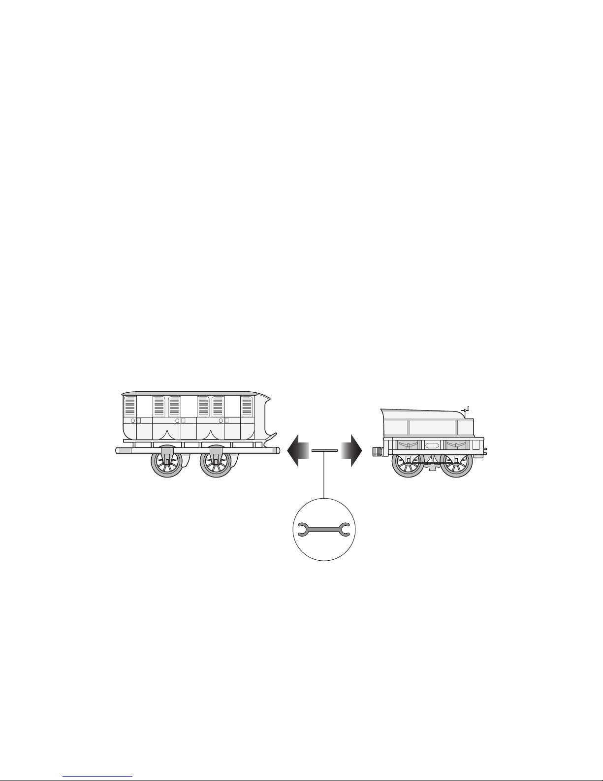
Vorbildgerechte Maul-Kupplung:
Fahrzeuge mit Kuppelstangen verbinden
Prototypical open jaw coupler:
Connect the locomotive and cars with coupling rods
Attelage à mâchoire fidèlement reproduit:
Relier les véhicules avec les barres d’accouplement
Voorbeeldgetrouwe klauwkoppeling:
Rijtuigen met koppelingstangen koppelen
Enganches fiel reproducidos:
Unir los vehículos con la barra de enganche
Gancio anteriore fedele al prototipo:
Collegare i rotabili con le barre di accoppiamento
Förebildstrogen kopplingslänk:
Fordonen förbinds med koppelstänger
Forebilledtro skruekobling:
Køretøjer forbindes med kobbelstænger
Page 5
5
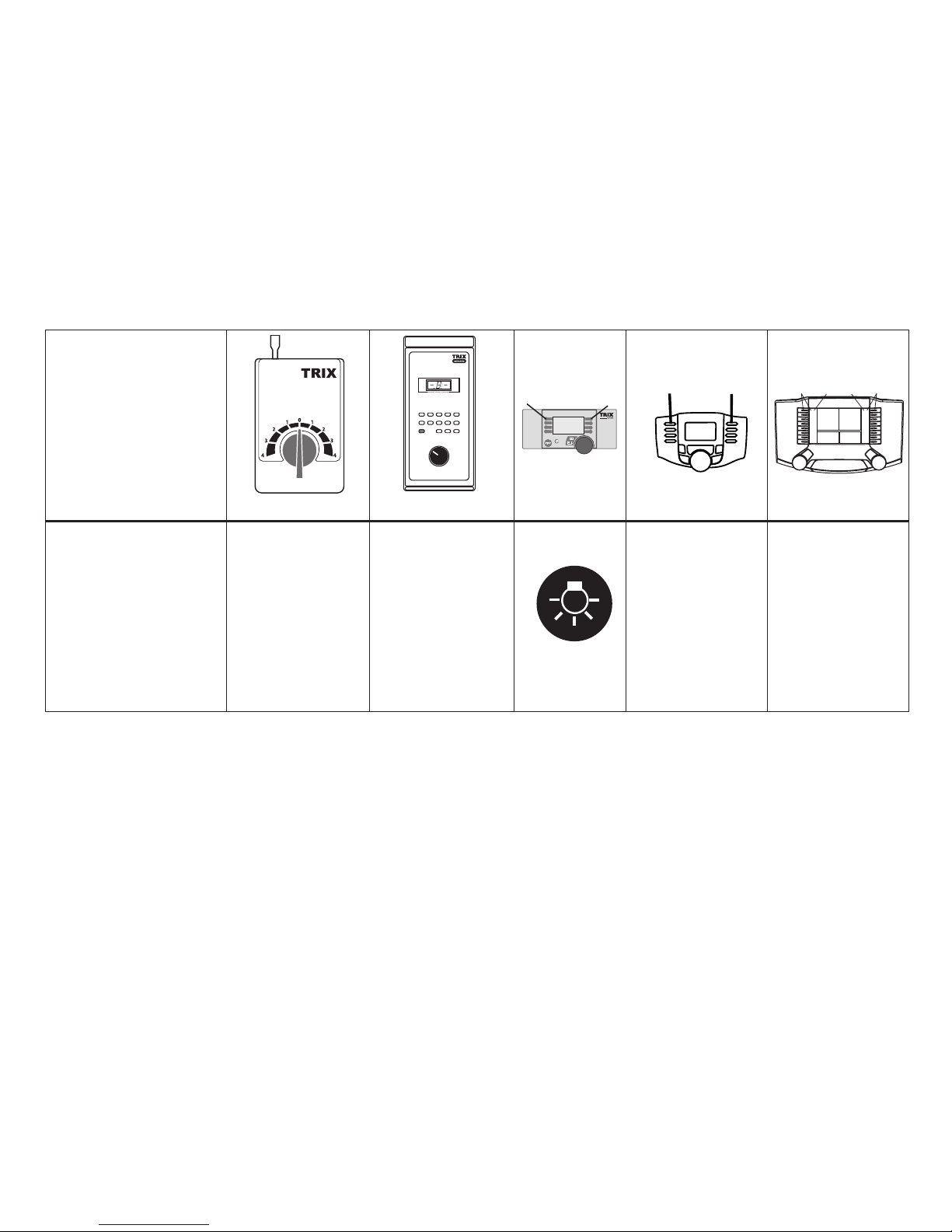
Schaltbare Funktionen
Controllable Functions
Fonctions commutables
Schakelbare functies
Funciones posibles
Funzioni commutabili
Kopplingsbara funktioner
Styrbare funktioner
Stirnbeleuchtung
Headlights
Fanal
Frontverlichting
Faros frontales
Illuminazione di testa
Frontstrålkastare
Frontbelysning
dauernd ein
Always on
Activé
Continu aan
Simpre encendido
Sempre accesa
Permanent till
Konstant tændt
Licht-Taste
Headlight button
Touche éclairage
Verlichtingstoets
Tecla de luz
Tasto illuminazion
e
Belysningsknapp
Belysningsknap
Funktion f0
Function f0
Fonction f0
Functie f0
Función f0
Funzione f0
Funktion f0
Funktionf0
Funktion f0
Function f0
Fonction f0
Functie f0
Función f0
Funzione f0
Funktion f0
Funktionf0
S
T
O
P
mobile station
1
5
271
6
STOP
PR
3
8
Sx
5
ON
Lz
4
9
1/2
Central-Control
66800
f0 - f3 f4 - f7
Page 6

6
Sicherheitshinweise
• Die Lok darf nur mit einem dafür bestimmten Betriebssystem eingesetzt werden.
• Nur Schaltnetzteile und Transformatoren verwenden, die
Ihrer örtlichen Netzspannung entsprechen.
•
Die Lok darf nur aus einer Leistungsquelle versorgt werden.
• Beachten Sie unbedingt die Sicherheitshinweise in der
Bedienungsanleitung zu Ihrem Betriebssystem.
• Setzen Sie das Modell keiner direkten Sonneneinstrah
lung, starken Temperaturschwankungen oder hoher
Luftfeuchtigkeit aus.
• Für den konventionellen Betrieb der Lok muss das An
schlussgleis entstört werden. Dazu ist das Entstörset
611 655 zu verwenden. Für Digitalbetrieb ist das Entstörset nicht geeignet.
Allgemeine Hinweise
•
Die Bedienungsanleitung und die Verpackung sind Bestandteil des Produktes und müssen deshalb aufbewahrt
sowie bei Weitergabe des Produktes mitgegeben werden.
• Für Reparaturen oder Ersatzteile wenden Sie sich bitte an
Ihren Trix-Fachhändler.
• http://www.maerklin.com/en/imprint.html
Jegliche Garantie-, Gewährleistungs- und Schadensersatzansprüche
sind ausgeschlossen, wenn in Trix-Produkten nicht von Trix freigegebene
Fremdteile eingebaut werden und / oder Trix-Produkte umgebaut werden
und die eingebauten Fremdteile bzw. der Umbau für sodann aufgetretene
Mängel und / oder Schäden ursächlich war. Die Darlegungs- und Beweislast dafür, dass der Einbau von Fremdteilen oder der Umbau in bzw. von
Trix-Produkten für aufgetretene Mängel und/oder Schäden nicht ursächlich
war, trägt die für den Ein- und / oder Umbau verantwortliche Person und/
oder Firma bzw. der Kunde.
Funktionen
• Eingebaute Elektronik zum wahlweisen Betrieb mit
konventionellem Gleichstrom-Fahrgerät (max. ±12 Volt),
Trix Systems, Trix Selectrix oder Digitalsystemen nach
NMRA-Norm.
• Automatische Systemerkennung zwischen Digital- und
Analog-Betrieb.
• Der volle Funktionsumfang ist nur unter Trix Systems und
unter DCC verfügbar.
• Eingebaute, fahrtrichtungsabhängige Stirnbeleuchtung.
Im Digitalbetrieb schaltbar.
Hinweis: Im Gleichstrom-Betrieb nie zu schnell von Vorwärts- auf
Rückwärtsfahrt oder umgekehrt umschalten. Drehregler immer
zuerst einen kurzen Moment in 0-Position stellen und danach erst
die Geschwindigkeit für die Gegenrichtung einstellen.
Hinweise zum Digitalbetrieb
•
Beim ersten Betrieb in einem Digital-System (Selectrix
oder DCC) muss der Decoder auf dieses Digital-System
eingestellt werden. Dazu ist der Decoder einmal in diesem
Digitalsystem zu programmieren (z.B. Adresse ändern).
• Adresse ab Werk: DCC 3/Sx 3
• Der Betrieb mit gegenpoliger Gleichspannung im
Bremsabschnitt ist mit der werkseitigen Einstellung
nicht möglich. Ist diese Eigenschaft gewünscht, so muss
auf den konventionellen Gleichstrombetrieb verzichtet
werden (CV 29 / Bit 2 = 0).
• Die einwandfreie Programmierung des Decoders für das
Selectrix-System kann nur mit den original Trix SelectrixKomponenten garantiert werden.
Page 7

7
* Änderungen unter Selectrix führen automatisch auch zu Änderungen unter DCC und umgekehrt.
*** Die Werte der gewünschten Einstellungen sind zu addieren!
• Technisch bedingt geht bei dem Fahrzeug im DCC-Betrieb bei ausgeschalteter Beleuchtungsfunktion und bei
Stillstand des Modells im Halteabschnitt das Licht an.
• Bei Verwendung einer Multi-Protokoll-Digital-Zentrale
als Betriebssystem ist diese Lok mit dem DCC-Format
zu steuern. Mit der Selectrix Digital-Zentrale kann das
Selectrix-Format genutzt werden.
CV Bedeutung Wert DCC Werkseinstellungen
1 * Adresse 1 - 127 3
3 Anfahrverzögerung 0 - 127 3
4 Bremsverzögerung 0 - 127 3
5 * Maximalgeschwindigkeit 1 - 7 7
17 Erweiterte Adresse (oberer Teil) CV 29, bit 5 =1 255
18 Erweiterte Adresse (unterer Teil) CV 29, bit 5 =1 255
29 Bit 0: Umpolung Fahrtrichtung
Bit 1: Anzahl Fahrstufen 14 oder 28/128
Bit 2: DCC Betrieb mit Bremsstrecke
DCC-, Selectrix- und Gleichstrombetrieb
Bit 5: Adressumfang 7 bit / 14 bit
Wert
0 / 1
0 / 2
0 / 4
0 / 32
***
0, 1, 2, 3, 4, 5, 6, 7,
32, 34, 35, 36, 37,
38, 39
6
49 * Impulsbreite zur Motorsteuerung 0 - 3 0
50 * Regelvariante 0 - 3 3
51 * Bit 0: Motorumpolung
Bit 1: Umpolung Licht
Bit 2: Umpolung Gleis
0 / 1
0 / 2
0 / 4
0 - 7
4
Page 8

8
of Trix products was not causal to the defects and / or damage arising, is
borne by the person and/or company responsible for the installation and /
or conversion, or by the customer.
Functions
• Built-in electronic circuit for operation with a conventional DC power pack (max. ±12 volts), Trix Systems,
Trix Selectrix or NMRA DCC digital systems.
• Automatic system recognition between digital and analog
operation.
• The full range of functions is only available under
Trix Systems and under DCC.
• Built-in headlights that change over with the direction of
travel. They can be turned on and off in digital operation.
Note: When in direct current operation, never switch too quickly from forward
to reverse travel (and vice versa). Always first move the control knob to the 0
position for a brief moment, then set the speed for the opposite direction.
Notes on digital operation
•
The first time the locomotive is used in a digital system
(Selectrix or DCC), the decoder must be set for this digital
system. To do this, the decoder must be programmed once
in this digital system (Example: changing an address).
• Address set at the factory: DCC 3/Sx 3
• The setting done at the factory does not permit operation
with opposite polarity DC power in the braking block.
If you want this characteristic, you must do without
conventional DC power operation (CV 29 / Bit 2 = 0).
• Trouble-free programming of the decoder can only be
guaranteed when it is done with original Trix Selectrix
components.
Safety Notes
• This locomotive is to be used only with an operating
system designed for it.
• Use only switched mode power supply units and transfor
-
mers that are designed for your local power system.
• This locomotive must never be supplied with power from
more than one power pack.
• Pay close attention to the safety notes in the instructions
for your operating system.
• Do not expose the model to direct sunlight, extreme
changes in temperature, or high humidity.
• The feeder track must be equipped to prevent inter
ference with radio and television reception, when the
locomotive is to be run in conventional operation. The
611 655 interference suppression set is to be used for this
purpose. The interference suppression set is not suitable
for digital operation.
General Notes
• The operating instructions and the packaging are a component part of the product and must therefore be kept as
well as transferred along with the product to others.
• Please see your authorized Trix dealer for repairs or
spare parts.
• http://www.maerklin.com/en/imprint.html
No warranty or damage claims shall be accepted in those cases where
parts neither manufactured nor approved by Trix have been installed in
Trix products or where Trix products have been converted in such a way
that the non-Trix parts or the conversion were causal to the defects and /
or damage arising. The burden of presenting evidence and the burden of
proof thereof, that the installation of non-Trix parts or the conversion in or
Page 9

9
* Changes done under Selectrix will automatically be carried out under DCC and vice versa.
*** The values for the desired settings must be added.
CV Discription DCC Value Factory Setting
1 * Adress 1 - 127 3
3 Acceleration delay 0 - 127 3
4 Braking delay 0 - 127 3
5 * Maximum speed 1 - 7 7
17 Extended address (upper part) CV 29, bit 5 =1 255
18 Extended address (lower part) CV 29, bit 5 =1 255
29 Bit 0: Travel direction polarity reversal
Bit 1: Number of speed levels 14 or 28/128
Bit 2: DCC Operation with braking Block.
DCC-, Selectrix- and DC power Operation
Bit 5: Adress size 7 bit / 14 bit
Value
0 / 1
0 / 2
0 / 4
0 / 32
***
0, 1, 2, 3, 4, 5, 6, 7,
32, 34, 35, 36, 37,
38, 39
6
49 * Pulse width for motor control 0 - 3 0
50 * Rule variant 0 - 3 3
51 * Bit 0: Motor polarity reversal
Bit 1: Headlight polarity reversal
Bit 2: Track polarity reversal
0 / 1
0 / 2
0 / 4
0 - 7
4
• T
he train has a technical feature in DCC operation
in
which its lights will go on when the lighting function is
turned off and the train is stopped in a block.
• When using a multiprotocol digital central unit as an
operating system, this locomotive should be controlled
with DCC format. The Selectrix digital central unit allows
Selectrix format to be employed.
Page 10

10
Remarques importantes sur la sécurité
• La locomotive ne peut être mise en service qu’avec un
système d’exploitation adéquat.
• Utiliser uniquement des convertisseurs et transforma
-
teurs correspondant à la tension du secteur local.
• La locomotive ne peut être alimentée en courant que par
une seule source de courant.
• Veuillez impérativement respecter les remarques sur la
sécurité décrites dans le mode d’emploi de votre système
d’exploitation.
• Ne pas exposer le modèle à un ensoleillement direct,
à de fortes variations de température ou à un taux
d‘humidité important.
• Pour l’exploitation de la locomotive en mode convention
nel, la voie de raccordement doit être déparasitée. A cet
effet, utiliser le set de déparasitage réf. 611 655. Le set de
déparasitage ne convient pas pour l’exploitation en mode
numérique.
Informations générales
• La notice d‘utilisation et l’emballage font partie intégrante
du produit ; ils doivent donc être conservés et, le cas
échéant, transmis avec le produit.
• Pour toute réparation ou remplacement de pièces, adres
-
sez vous à votre détaillant-spécialiste Trix.
• http://www.maerklin.com/en/imprint.html
Tout recours à une garantie commerciale ou contractuelle ou à une
demande de dommages-intérêt est exclu si des pièces non autorisées par
Trix sont intégrées dans les produits Trix et / ou si les produits Trix sont
transformés et si les pièces d’autres fabricants montées ou la transformation constituent la cause des défauts et/ou dommages apparus. C’est à la
personne et / ou la société responsable du montage / de la transformation
ou au client qu’incombe la charge de prouver que le montage des pièces
d’autres fabricants sur des produits Trix ou la transformation des produits
Trix n’est pas à l’origine des défauts et ou dommages apparus.
Fonctionnement
• Electronique intégrée pour exploitation au choix avec
transformateur-régulateur conventionnel délivrant du
courant continu (max. ±12 volts), avec Trix Systems, avec
Trix Selectrix ou avec des systèmes de conduite digitale
conformes aux normes NMRA.
• Reconnaissance automatique du système entre exploita
-
tions numérique et analogique.
• L’intégralité des fonctions est disponible uniquement en
exploitation Trix Systems et DCC.
• Feux de signalisation s‘inversant selon le sens de marche; feux commutables en exploitation digital.
Remarque: en mode courant continu, ne jamais commuter rapidement de la
marche avant à la marche arrière ou inversement. Toujours mettre le commutateur rotatif d‘abord en position 0 pendant un court instant et ne régler
qu‘ensuite la vitesse de la marche dans le sens opposé.
Remarques relatives au fonctionnement en mode digital
•
Une première exploitation en système numérique (Selectrix ou DCC) exige le réglage correspondant du décodeur.
A cet effet, le décodeur doit être programmé une fois dans
ce système numérique (par ex., modifier l’adresse).
• Adresse encodée en usine:DCC 3/Sx 3
•
L’exploitation avec courant continu de polarité inverse dans
les sections de freinage n’est pas possible avec le réglage
d’usine. Si cette propriété est désirée, il faut alors renoncer
à l’exploitation conventionnelle en courant continu (CV 29 /
Bit 2 = 0).
Page 11

11
* Toute modification effectuée sous Selectrix entraîne automatiquement une modification sous DCC et inversement.
*** Les valeurs des réglages désirés sont à additioner.
•
Une programmation du décodeur pour le système
Selectrix ne peut être garantie sans problème qu‘avec des
composants originaux Trix Selectrix.
•
Pour des raisons techniques, en cas d‘exploitation en
système DCC, l‘éclairage peut s‘allumer lorsque la fonction
éclairage est désactivée et lors de l‘arrêt du train sur une
section d‘arrêt.
• Si vous utilisez un système Digital avec multiprotocoles
comme système d‘exploitation, cette locomotive doit être
commandée avec le format DCC. Avec le système Digital
Selectrix, il est possible d‘utiliser le format Selectrix.
CV Signification Vaieur DCC Valeur Parm. Usine
1 * Adresse 1 - 127 3
3 Temporisation d‘accélération 0 - 127 3
4 Temporisation de freinage 0 - 127 3
5 * Vitesse maximale 1 - 7 7
17 Adresse étendue (partie supérieure) CV 29, bit 5 =1 255
18 Adresse étendue (partie inférieure) CV 29, bit 5 =1 255
29 Bit 0: Inversion de polarité, sens de marche
Bit 1: Nombre de crans de marche 14 ou 28/128
Bit 2: Exploitation DCC avec zone de freinage.
DCC, Selectrix et courant continu
Bit 5: Taille d‘adresse 7 bit / 14 bit
Vaieur
0 / 1
0 / 2
0 / 4
0 / 32
***
0, 1, 2, 3, 4, 5, 6, 7,
32, 34, 35, 36, 37,
38, 39
6
49 * Largeur d‘impulsion de cammande moteur 0 - 3 0
50 * Variante de réglage 0 - 3 3
51 * Bit 0: Inversion de polarité du moteur
Bit 1: Inversion éclairage
Bit 2: Inversion de polaritè
0 / 1
0 / 2
0 / 4
0 - 7
4
Page 12

12
Veiligheidsvoorschriften
• De loc mag alleen met een daarvoor bestemd bedrijfssysteem gebruikt worden.
• Alleen net-adapters en transformatoren gebruiken
waarvan de aangegeven netspanning overeenkomt met
de netspanning ter plaatse.
• De loc mag niet vanuit meer dan één stroomvoorziening
gelijktijdig gevoed worden.
• Lees ook aandachtig de veiligheidsvoorschriften in de
gebruiksaanwijzing van uw bedrijfssysteem.
• Stel het model niet bloot aan in directe zonnestraling,
sterke temperatuurwisselingen of hoge luchtvochtigheid.
• Voor het conventionele bedrijf met de loc dient de
aansluitrail te worden ontstoort. Hiervoor dient men de
ontstoor-set 611 655 te gebruiken. Voor het digitale bedrijf
is deze ontstoor-set niet geschikt.
Algemene informatie
• De gebruiksaanwijzing en de verpakking zijn een bestanddeel van het product en dienen derhalve bewaard
en meegeleverd te worden bij het doorgeven van het
product.
• Voor reparaties en onderdelen kunt zich tot Uw Trix
handelaar wenden.
• http://www.maerklin.com/en/imprint.html
Elke aanspraak op garantie en schadevergoeding is uitgesloten, wanneer
in Trix-producten niet door Trix vrijgegeven vreemde onderdelen ingebouwd en / of Trix-producten omgebouwd worden en de ingebouwde vreemde
onderdelen resp. de ombouw oorzaak van nadien opgetreden defecten
en / of schade was. De aantoonplicht en de bewijslijst daaromtrent, dat
de inbouw van vreemde onderdelen in Trix-producten of de ombouw van
Trix-producten niet de oorzaak van opgetreden defecten en / of schade is
geweest, berust bij de voor de inbouw en / of ombouw verantwoordelijke
persoon en / of firma danwel bij de klant.
Functies
• Ingebouwde elektronica die het mogelijk maakt om naar
keuze met, een conventionele gelijkstroomrijregelaar
(max. ±12 Volt), Trix Systems, Trix Selectrix of digitaalsys
-
teem volgens NMRA-norm te rijden.
• Automatische systeemherkenning tussen digitaal- en
analoogbedrijf.
• De volledige toegang tot alle functies is alleen mogelijk
met Trix Systems of met DCC bedrijf.
• Ingebouwde, rijrichtingsafhankelijke frontverlichting.
Aanwijzing: In gelijkstroom-bedrijf nooit te snel van vooruit- op achteruitrijden
of vice versa omschakelen. Draairegelaar altijd eerst even in de 0-positie
zetten en vervolgens eerst de snelheid voor de tegenrichting instellen.
Aanwijzingen voor digitale besturing
• Voor het eerste bedrijf met een digitaal-systeem (Selectrix of DCC) moet de decoder op dat digitale systeem
worden ingesteld. Daarvoor moet de decoder éénmaal
met dat digitale systeem geprogrammeerd worden (bijv.
adres wijzigen).
• Van af de fabriek:DCC 3/Sx 3
• Het bedrijf met tegengepoolde gelijkspanning in de
afremsectie is met de fabrieksinstelling niet mogelijk.
Indien deze eigenschap wenselijk is, dan moet worden
afgezien van het conventioneel gelijkstroombedrijf
(CV 29 / Bit 2 = 0).
•
Het probleemloos programmeren van de decoder voor het
Selectrix-systeem kan alleen bij het gebruik van de originele
Page 13

13
* Wijzigingen doorgevoerd met Selectrix leiden automatisch tot wijzigingen bij DCC en omgekeerd.
*** De waarde van de gewenste instellingen moeten bij elkaar opgeteld worden.
CV Betekenis Waarde DCC Fabriesinstelling
1 * Adres 1 - 127 3
3 Optrekvertraging 0 - 127 3
4 Afremvertraging 0 - 127 3
5 * Maximumsnelheid 1 - 7 7
17 Uitgebreld adres (bovenste gedeelte) CV 29, bit 5 =1 255
18 Uitgebreld adres (onderste gedeelte) CV 29, bit 5 =1 255
29 Bit 0: ompoling rijrichting
Bit 1: aantal rijstappen 14 of 28/128
Bit 2: DCC-bedrijf met afremtraject.
DCC-, Selectrix- en gelijkstroombedrijf
Bit 5: adresbereik 7 bit / 14 bit
Waarde
0 / 1
0 / 2
0 / 4
0 / 32
***
0, 1, 2, 3, 4, 5, 6, 7,
32, 34, 35, 36, 37,
38, 39
6
49 * Impulsbreedte vor de motorsturing 0 - 3 0
50 * Relingsvariant 0 - 3 3
51 * Bit 0: motorompoling
Bit 1: ompoling licht
Bit 2: ompoling rails
0 / 1
0 / 2
0 / 4
0 - 7
4
Trix Selectrix componenten gegarandeerd worden.
• Vanwege de techniek gaat bij de trein, in het DCC-bedrijf
bij uitgeschakelde verlichtingsfunctie en bij het stilstaan
van het model in een stopsectie, de verlichting aan.
• Bij gebruik van een digitale multi-protocol-centrale als
besturingssysteem moet deze lok in DCCformaat worden
bestuurd. Bij toepassing
van de digitale Selectrix centrale kan het Selectrix-formaat gehanteerd worden.
Page 14

14
Aviso de seguridad
• La locomotora solamente debe funcionar en el sistema
que le corresponda.
•
Emplear únicamente fuentes de alimentación conmutadas
y transformadores que sean de la tensión de red local.
• La locomotora no deberá recibir corriente eléctrica mas
que de un solo punto de abasto.
•
Observe bajo todos los conceptos, las medidas de
seguridad indicadas en las instrucciones de su sistema de
funcionamiento.
• No exponer el modelo en miniatura a la radiación solar
directa, a oscilaciones fuertes de temperatura o a una
humedad del aire elevada.
• Para el funcionamiento convencional de la locomotora
deben suprimirse las interferencias en la vía de conexión
de la alimentación. Para ello debe emplearse el set
supresor de interferencias 611 655. El set supresor de
interferencias no es adecuado para el funcionamiento en
modo digital.
Informaciones generales
• Las instrucciones de empleo y el embalaje forman parte
íntegra del producto y, por este motivo, deben guardarse
y entregarse junto con el producto en el caso de venderlo
o transmitirlo a otro.
•
En caso de precisar una reparación o piezas de recambio,
rogamos ponerse en contacto con su distribuidor Trix.
• http://www.maerklin.com/en/imprint.html
Se excluye todo derecho de garantía, prestación de garantía e indemnización
sobre aquellos productos Trix en los que se hubieran montado piezas ajenas
no autorizadas por Trix y/o sobre aquellos productos Trix que hayan sido modi-
ficados cuando la piezas ajenas montadas o la modificación sean las causas
de los desperfectos y/o daños posteriormente surgidos. La persona y/o empresa o el cliente responsable del montaje o modificación será el responsable
de probar y alegar que el montaje de piezas ajenas o la modificación en/de
productos Trix no son las causas de los desperfectos y/o daños surgidos.
Funciones
• Electrónica incorporada para un funcionamiento a discreción en corriente continua convencional (máx. ±12 V.), Trix
Systems, Trix Selectrix o sistemas Digital según las normas
NMRA.
• Detección automática del sistema entre los modos digital
y analógico.
• La plena funcionalidad de funciones está disponible sólo
en Trix Systems y en DCC.
• Los faros frontales dependen del sentido de la marcha.
En Digital se pueden encender y apagar.
Nota: en modo de corriente continua nunca se debe cambiar de forma
demasiado rápida de marcha hacia atrás a marcha hacia adelante o
viceversa. Poner primero siempre durante un breve espacio de tiempo el
transformador giratorio en la posición 0 y después ajustar la velocidad del
sentido contrario.
Indicaciones para el funcionamiento digital
• En el funcionamiento por primera vez en un sistema
digital (Selectrix o DCC), debe configurarse el decoder
para este sistema digital. Para tal fin, el decoder debe
programarse una vez en este sistema digital (p. ej. debe
cambiarse la dirección).
• Código de fábrica:DCC 3/Sx 3
• No es posible el funcionamiento con tensión de corriente
continua de polaridad opuesta en el tramo de frenado en
funcionamiento en modo DCC. Si se desea esta caracterí-
Page 15

15
* Los cambio en el modo Selectrix provocan también cambios automáticamente en DCC y viceversa.
*** ¡Los valores de los ajustes deseados deben sumarse!
stica, debe renunciarse al funcionamiento convencional
con corriente continua (CV 29 / Bit 2 = 0).
• Una programación sin problemas del decoder dentro del
sistema Selectrix solamente se puede garantizar si se
usan componentes originales Trix Selectrix.
•
Por motivos técnicos en funcionamiento DCC a iluminación
del modelo se enciende con la función luz apagada o
estando el tren parado en un sector sin corriente.
• Si se utiliza una central digital multiprotocolo como
sistema operativo, esta locomotora deberá controlarse
con formato DCC. Con la central digital Selectrix, puede
utilizarse el formato Selectrix.
CV
Significado
Valor DCC Ajuste de fábrica
1 * Códigos 1 - 127 3
3 Arranque progresivo 0 - 127 3
4 Frenado progresivo 0 - 127 3
5 * Velocidad máxima 1 - 7 7
17 Dirección ampliada (parte superior) CV 29, bit 5 =1 255
18 Dirección ampliada (parte inferior) CV 29, bit 5 =1 255
29
Bit 0: inversión de la polaridad, sentido de la marcha + luces
Bit 1: pasos de velocidad 14 o 28/128
Bit 2: DCC Funciono freno
DCC-, Selectrix- y corriente continua
Bit 5: capacidad de códigos 7 bit / 14 bit
Valor
0 / 1
0 / 2
0 / 4
0 / 32
***
0, 1, 2, 3, 4, 5, 6, 7, 32,
34, 35, 36, 37, 38, 39
6
49 * Amplitud de impulsos para el gobierno del motor 0 - 3 0
50 * Variante de réglage 0 - 3 3
51 * Bit 0: inversión de la polaridad del motor
Bit 1: sólo luces
Bit 2: inversión de la polaridad de la vía
0 / 1
0 / 2
0 / 4
0 - 7
4
Page 16

16
Avvertenze per la sicurezza
• Tale locomotiva deve venire impiegata soltanto con un
sistema di esercizio prestabilito a questo scopo.
• Impiegare soltanto alimentatori “switching“ e trasforma
-
tori che corrispondono alla Vostra tensione di rete locale.
• Loket får inte samtidigt försörjas av mer än en kraftkälla.
• Vogliate prestare assolutamente attenzione alle avverten
ze di sicurezza nelle istruzioni di impiego per il Vostro
sistema di funzionamento.
• Non esponete tale modello ad alcun irraggiamento solare
diretto, a forti escursioni di temperatura oppure a elevata
umidità dell’aria.
• Per il funzionamento tradizionale della locomotiva il
binario di alimentazione deve essere protetto dai disturbi.
A tale scopo si deve impiegare il corredo antidisturbi
611 655. Tale corredo antidisturbi non è adatto per il
funzionamento Digital.
Avvertenze generali
• Le istruzioni di impiego e l’imballaggio costituiscono un
componente sostanziale del prodotto e devono pertanto
venire conservati nonché consegnati insieme in caso di
ulteriore cessione del prodotto.
• Per riparazioni oppure parti di ricambio Vi preghiamo di
rivolgerVi al Vostro rivenditore specializzato Trix.
• http://www.maerklin.com/en/imprint.html
Trix non fornisce alcuna garanzia, assicurazione e risarcimento danni in
caso di montaggio sui prodotti Trix di componenti non espressamente
approvati dalla ditta. Trix altresì non risponde in caso di modifiche al
prodotto, qualora i difetti e i danni riscontrati sullo stesso siano stati causati
da modifiche non autorizzate o dal montaggio di componente esterni da lei
non approvati. L‘onere della prova che i componenti montati e le modifiche
apportate non sono state la causa del danno o del difetto, resta a carico del
cliente o della persona / ditta che ha effettuato il montaggio di componenti
estranei o che ha apportato modifiche non autorizzate.
Funzioni
• Modulo elettronico incorporato per il funzionamento a
scelta con un tradizionale regolatore di marcia in corrente continua (max. 12 volt), Trix Systems, Trix Selectrix
oppure sistemi digitali in base alla normativa NMRA.
• Riconoscimento automatico del sistema tra esercizio
Digital ed analogico.
• La completa dotazione di funzioni è disponibile soltanto
sotto Trix Systems e sotto DCC.
• IIlluminazione di testa incorporata, dipendente dalla direzione di marcia. Commutabile nel funzionamento Digital.
Nota: durante il funzionamento in corrente continua il passaggio dalla
marcia in avanti alla retromarcia non deve essere troppo rapido. Lasciare
per qualche istante il regolatore rotativo nella posizione 0 e solo successivamente regolare la velocità per il senso di marcia.
Istruzioni per la funzione digitale
•
In occasione del primo funzionamento in un dato sistema
digitale (Selectrix oppure DCC) il Decoder deve venire
impostato su questo sistema Digital. A tal fine si deve
programmare almeno una volta il Decoder in questo
sistema digitale.
• Indirizzo di fabbrica:DCC 3/Sx 3
• Un funzionamento con tensione continua di polarità invertita
nella sezione di frenatura, in caso di esercizio con DCC, non
è possibile. Se si desidera questa caratteristica, si deve in
tal caso rinunciare al funzionamento tradizionale in corrente
continua (CV29 / Bit 2 = 0).
Page 17

17
* Le variazioni sotto Selectrix conducono automaticamente anche a variazioni sotto DCC e viceversa.
*** I valori delle impostazioni desiderate si devono sommare!
CV Significato Valore DCC
Dato di fabbrica
1 * Indirizzo 1 - 127 3
3 Ritardo di avviamento 0 - 127 3
4 Ritardo di frenatura 0 - 127 3
5 * Velocità massima 1 - 7 7
17 Indirizzo ampliato (parte superiore) CV 29, bit 5 =1 255
18 Indirizzo ampliato (parte inferiore) CV 29, bit 5 =1 255
29 Bit 0: Inversione di polarità senso di marcia+luce
Bit 1: Numero dei livelli di marcia 14 o 28/128
Bit 2: DCC sistemi freni
DCC-, Selectrix- e corrente continua
Bit 5: Estensione dell’indirizzo 7 bit / 14 bit
Valore
0 / 1
0 / 2
0 / 4
0 / 32
***
0, 1, 2, 3, 4, 5, 6, 7,
32, 34, 35, 36, 37,
38, 39
6
49 * Ampiezza degli impulsi di comando del motore 0 - 3 0
50 * Variante di regolazione 0 - 3 3
51 * Bit 0: Inversione di polarità motore
Bit 1: Solo luce
Bit 2: Inversione di polarità binario
0 / 1
0 / 2
0 / 4
0 - 7
4
• La programmazione senza inconvenienti del Decoder per
il sistema Selectrix può venire garantita soltanto con i
componenti originali Trix Selectrix.
•
Per ragioni tecniche, nel rotabile nel funzinamento DCC
con funzione di illuminazione disattivata e durante la fermata del modello nella sezione di arresto la luce si spegne.
• Se come sistema operativo si utilizza un‘unità centrale
digitale multiprotocollo, comandare la locomotiva con il
formato dei dati DCC. Con l‘unità centrale digitale Selectrix è possibile utilizzare il formato Selectrix.
Page 18

18
Säkerhetsanvisningar
• Loket får endast köras med därtill avsett driftsystem.
• Använd endast nätadaptrar och transformatorer anpas
-
sade för det lokala elnätet.
• Loket får inte samtidigt försörjas av mer än en kraftkälla.
• Beakta alltid säkerhetsanvisningarna i bruksanvisningen
som hör till respektive driftsystemet.
• Modellen får inte utsättas för direkt solljus, häftiga tem
-
peraturväxlingar eller hög luftfuktighet.
• När den motorförsedda lokdelen ska köras med konventi
onell drift måste anlutningsskenan vara avstörd. Till detta
använder man anslutningsgarnityr 611 655 med avstörning och överbelastningsskydd. Avstörningsskyddet får
inte användas vid digital körning.
Allmänna informationer
• Bruksanvisningen och förpackningen är en del av
produkten och måste därför sparas och alltid medfölja
produkten.
• Kontakta din Trix-handlare för reparationer eller reserv
-
delar.
• http://www.maerklin.com/en/imprint.html
Varje form av anspråk på garanti och skadestånd är utesluten om delar
används i Trix-produkter som inte har godkänts av Trix och / eller om Trixprodukter har modifi erats och de inbyggda främmande delarna resp. modifi
eringen var upphov till de därefter uppträdande felen och / eller skadorna.
Bevisbördan för att inbyggnaden av främmande delar i eller ombyggnaden
av Trix-produkter inte är upphovet till de uppträdande felen och / eller
skadorna, bär den person och / eller företag resp. kund som är ansvarig för
in- och / eller ombyggnaden.
Funktioner
• Inbyggd elektronik för valfri drift med konventionell likströmskörenhet (max ±12 Volt), Trix Systems, Trix Seletrix
eller Digitalsystem enligt NMRA-standard.
• Automatisk system-igenkänning mellan digital- och
analogtrafik.
• Fullständigt funktionsomfång erhålls endast vid använd
-
ning av Trix Systems eller DCC.
• Körriktningsberoende frontbelysning.
Kan kopplas in vid digital drift.
Observera: Vid likströmsdrift får aldrig omkoppling ske för snabbt från körning fram
till backning eller vice versa. Vrid först körenheten till 0-läget och låt den stå kvar
där ett ögonblick, innan du ställer in hastigheten för den motsatta körriktningen.
Anvisningar för digital drift
• Vid första körningen på ett digital-system (Selectrix eller
DCC) så måste dekodern ställas in för just detta digitalsystem. Därför måste man programmera dekodern en
gång för det aktuella digitalsystemet.
• Adress från tillverkaren:DCC 3/Sx 3
• Vid DCC-drift kan man inte köra med tvåpolig
likspänning på ett bromsavsnitt. Önskar man ändå
genomföra en sådan körning, så måste man förlita sig på
konventionell likströmsdrift. (CV29 / Bit 2 = 0).
•
Rätt programmering av dekodern för Selectrix systemet
garanteras endast med original Trix´Selectrix komponenter.
Page 19

19
* Ändringar i Selectrix medför automatiskt motsvarande ändringar i DCC och tvärtom.
*** De önskade inställningarnas värden ska adderas/läggas samman!
CV Betydelse Värde DCC Förinställning
1 * Adress 1 - 127 3
3 Accelerationsfördröjning 0 - 127 3
4 Bromsfördröjning 0 - 127 3
5 * Maxfart 1 - 7 7
17 Utvidgad adress (övre del) CV 29, bit 5 =1 255
18 Utvidgad adress (undre del) CV 29, bit 5 =1 255
29 Bit 0: Polvändning körriktning + belysning
Bit 1: Antal körsteg 14 eller 28/128
Bit 2: DCC Driftsystem bromser
DCC-Selectrix och likström
Bit 5: Adressomfång 7 bit / 14 bit
Värde
0 / 1
0 / 2
0 / 4
0 / 32
***
0, 1, 2, 3, 4, 5, 6, 7,
32, 34, 35, 36, 37,
38, 39
6
49 * Impulsbredd för motorstyrning 0 - 3 0
50 * Regleringsvariant 0 - 3 3
51 * Bit 0: Polvändning av motor
Bit 1: Endast belysning
Bit 2: Polvändning räls
0 / 1
0 / 2
0 / 4
0 - 7
4
• Beroende på tekniken går fordonet vid DCC-drift med
släckt belysning och vid modellens stillestånd på
stoppsträckan tänds belysningen.
•
När en Multi-Protokoll-Digital-Central användssom
riftssystem, ska detta lok styras med DCC-formatet. Med
Selectrix digitala central, kan Selectrix-formatet användas.
Page 20

20
Vink om sikkerhed
• Lokomotivet må kun anvendes med et driftssystem, der er
beregnet dertil.
• Anvend kun DC-DC-omformere og transformatorer, der
passer til den lokale netspænding.
• Lokomotivet må ikke forsynes fra mere end én strømkilde
ad gangen.
• Vær under alle omstændigheder opmærksom på de vink
om sikkerhed, som findes i brugsanvisningen for Deres
driftssystem.
• Modellen må ikke udsættes for direkte sollys, store
temperaturudsving eller høj luftfugtighed.
• Ved konventionel drift af lokomotivet skal tilslutningssporet
støjdæmpes. Dertil skal anvendes støjdæmpningssættet
611 655. Støjdæmpningssættet er ikke egnet til digital drift.
Generelle oplysninger
• Betjeningsvejledning og emballage hører til produktet og
skal derfor gemmes og medfølge, hvis produktet gives
videre til andre.
• Angående reparationer eller reservedele bedes De
henvende Dem til Deres Trix-forhandler.
• http://www.maerklin.com/en/imprint.html
Ethvert garanti-, mangelsansvars- og skadeserstatningskrav er udelukket,
hvis der indbygges fremmeddele i Trixprodukter, der ikke er frigivet dertil af
Trix og / eller hvis Trixprodukter bygges om og de indbyggede fremmeddele
hhv. ombygningen var årsag til sådanne opståede mangler og / eller skader.
Det påhviler kunden hhv. den person og/eller det fi rma, der er ansvarlig for
ind- og / eller ombygningen, at påvise hhv. bevise, at indbygningen af fremmeddele i, eller ombygningen af Trixprodukter ikke var årsag til opståede
mangler og / eller skader.
Funktioner
• Indbygget elektronik til valgfri drift med konventionelt
jævnstrømskøreudstyr (maks. ±12 volt), Trix Systems,
Trix Selectrix eller Digitalsystemer efter NMRA-norm.
• Automatisk systemgenkendelse mellem digital- og ana
-
logdrift.
• Det komplette funktionsomfang er kun til rådighed under
Trix Systems og under DCC.
• Innebygd, kjøreretningsavhengig frontlys.
Kan tændes og slukkes til digitaldrift.
Bemærkning: Skift aldrig for hurtigt om fra fremtil baglænskørsel eller omvendt under jævnstrømsdrift. Lad drejeregulatoren altid først stå i 0-position
et øjeblik, før hastigheden for kørsel i modsat retning vælges.
Henvisninger til digitaldrift
• Ved første drift i et Digitalsystem (Selectrix eller DCC) skal
dekoderen på dette Digitalsystem indstilles. Dertil skal
dekoderen programmeres én gang i dette Digitalsystem.
• Adresse ab fabrik:DCC 3/Sx 3
• Det er ved DCC-drift ikke muligt at anvende drift med
modpolet jævnspænding i bremseafsnittet. Hvis denne
egenskab ønskes, må der gives afkald på den konventionelle jævnstrømsdrift. (CV29 / Bit 2 = 0).
• En fejlfri programmering af dekoderen for Selectrixsys
temet kan kun garanteres med de originale Trix Selectrix
komponenter.
•
Teknisk betinget tændes lyset, når modellen ved DCC-drift
står stille i holdeafsnittet med slukket belysningsfunktion.
Page 21

21
* Ændringer under Selectrix medfører automatisk også ændringer under DCC og omvendt.
*** Værdierne for de ønskede indstillinger skal lægges sammen!
CV Betydning Værdi DCC Indstillinger fra
fabrikken
1 * Adress 1 - 127 3
3 Opstartforsinkelse 0 - 127 3
4 Bremseforsinkelse 0 - 127 3
5 * Maksimalhastighed 1 - 7 7
17 Udvidet adresse (Øverste del) CV 29, bit 5 =1 255
18 Udvidet adresse (Nederste del) CV 29, bit 5 =1 255
29 Bit 0: Ompoling kørselsretning + lys
Bit 1: Antal køretrin 14 eller 28/128
Bit 2: DCC driftssystemer med bremse
DCC-Selectrix og Jævnstrøm
Bit 5: Adresseomfang 7 bit / 14 bit
Værdi
0 / 1
0 / 2
0 / 4
0 / 32
***
0, 1, 2, 3, 4, 5, 6, 7,
32, 34, 35, 36, 37,
38, 39
6
49 * Impulsbredde til motorstyring 0 - 3 0
50 * Reguleringsvarianter 0 - 3 3
51 * Bit 0: Motorompoling
Bit 1: kun lys
Bit 2: Ompoling spor
0 / 1
0 / 2
0 / 4
0 - 7
4
• Ved anvendelse af en multiprotokol-Digitalcentral som
driftssystem skal dette lokomotiv styres med DCC-formatet. Ved drift med Selectrix Digitalcentralen kan Selectrixformatet anvendes.
Page 22

22
Motor bitte nicht ölen!
Do not oil the motor!
Ne pas huiler le moteur!
Motor niet oliën!
¡Por favor no engrase el motor!
Si prega di non lubrificare il motore!
V g smörj ej motorn!
De bedes ikke smøre motoren!
Trix 66625
Märklin 7149
40h
Page 23

23
Trix
Page 24

24
Page 25

25
Page 26

26
25
26
27
28
29
33
31
33
32
33
31
30
33
34
29
35
35
36
36
32
1
2
4
7
6
5
8
14
8
12
11
13
10
18
10
21
15
17
16
19
20
23
22
24
24
52
34
9
53
52
47
46
48
45
44
39
37
38
39
51
50
51
54
49
42
41
56
57
55
59
43
58
60
Details der Darstellung können
von dem Modell abweichen.
Page 27

27
1 Rauchkammervorderwand 154 828
2 Laterne 154 914
3 Laternenrückwand 154 915
4 Decoder 106 945
5 Rauchkammer mit Kamin 154 719
6 Kontaktfeder 301 265
7 Zylinderschraube 19 7098 28
8 Kesselträger vorne 154 831
9 Kesselträger mitte 154 806
10 Kesselträger hinten 154 832
11 Langkessel 154 829
12 Druckfeder 15 0109 00
13 Pfeife 14 0525 24
14 Zugstange 154 821
15 Stehkessel 301 086
16 Überdruckventil 154 823
17 Schraube 19 7098 28
18 Feuerbuchse 301 257
19 Stehkesselrückwand 154 830
20 Schiebergestänge 154 813
21 Umsteuerungshebel 154 817
22 Geländer links 154 788
23 Geländer rechts 154 787
24 Radabdeckung 154 797
25 Rahmen 154 717
26 Puffer 301 109
27 Zugvorrichtung 154 794
28 Sprengwerk 154 837
29 Schraube 19 7098 28
30 Treibradsatz 154 863
31 Achslager 154 798
32 Laufradsatz 154 858
33 Achslager 154 786
34 Innenrahmen 154 800
35 Pleul 154 809
36 Kreuzkopf 154 807
Tender montiert
37 Aufbau 154 855
38 Handkurbel 154 789
39 Handstange 154 822
40 Kohleneinsatz 301 261
41 Zugvorrichtung OT 154 840
42 Zugvorrichtung UT 154 842
43 Zylinderschraube 301 256
44 Motor 301 205
45 Getriebewelle 301 199
46 Rahmen 154 723
47 Sprengwerk 154 853
48 Puffer 301 196
49 Kupplungsdeichsel 154 838
50 Lötfahne 13 1709 00
51 Zylinderschraube 19 8052 28
52 Treppe 301 249
53 Tenderbremse 154 844
54 Radschleifer 154 870
55 Radsatz 154 867
56 Radsatz mit Haftreifen 154 868
57 Haftreifen 7 154
58 Kontaktplatte 301 216
59 Achshalter mit Schleifer 154 870
60 Zylinderschraube 19 7099 28
Page 28

This device complies with Part 15 of the FCC Rules.
Operation is subject to the following two conditions:
(1) This device may not cause harmful interference, and
(2) this device must accept any interference received, including
interference that may cause undesired operation.
Gebr. Märklin & Cie. GmbH
Stuttgarter Str. 55 - 57
73033 Göppingen
Deutschland
www.trix.de
157090/0610/Ha1Ef
Änderungen vorbehalten
© Gebr. Märklin & Cie. GmbH
 Loading...