

Page 1
Modell der Dampfl ok BR 38
22382
D
GB
F
USA
NL
Page 2

2
Page 3

3
Inhaltsverzeichnis: Seite
Informationen zum Vorbild 4
Hinweise zur Inbetriebnahme 6
Sicherheitshinweise 8
Wichtige Hinweise 8
Multiprotokollbetrieb 8
Hinweise zum Digitalbetrieb 9
Schaltbare Funktionen 11
Parameter/Register 12
Ergänzendes Zubehör 28
Wartung und Instandhaltung 30
Ersatzteile 36
Table of Contents: Page
Information about the prototype 4
Notes about using this model for the first time 6
Safety Notes 13
Important Notes 13
Multi-Protocol Operation 13
Notes on digital operation 14
Controllable Functions 16
Parameter/Register 17
Completing accessories 28
Service and maintenance 30
Spare Parts 36
Sommaire : Page
Informations concernant la locomotive réelle 5
Indications relatives à la mise en service 6
Remarques importantes sur la sécurité 18
Information importante 18
Mode multiprotocole 18
Remarques relatives au fonctionnement
en mode digital 19
Fonctions commutables 21
Paramètre/Registre 22
Accessoires complémentaires 28
Entretien et maintien 30
Pièces de rechange 36
Inhoudsopgave: Pagina
Informatie van het voorbeeld 5
Opmerking voor de ingebruikname 6
Veiligheidsvoorschriften 23
Belangrijke aanwijzing 23
Multiprotocolbedrijf 23
Aanwijzingen voor digitale besturing 24
Schakelbare functies 26
Parameter/Register 27
Aanvullende toebehoren 28
Onderhoud en handhaving 30
Onderdelen 36
Page 4

4
Informationen zum Vorbild
Die von Robert Garbe konstruierte preußische P 8 war eine
in ihren Leistungen derart befriedigende und beim Personal
beliebte Lokomotive, dass von in- und ausländischen
Bahnverwaltungen bis zum Jahre 1928 ungefähr 3800 Maschinen beschafft wurden. Beim Übergang auf die Deutsche
Reichsbahn erhielten die preußischen Lokomotiven die
Baureihenbezeichnung 38
10-40
.
Wurde die P8 vom Ursprung her schon in verschiedenen
Variationen gebaut, kamen während ihrer langen Einsatzzeit
noch zahlreiche An- und Umbauten hinzu. Beispiele
hierfür sind geänderte Rauchkammertüren, Anbau von
Windleitblechen der Bauart Witte sowie der Austausch der
Kastentender gegen Wannentender. Die letzten Modelle der
Baureihe 38 wurden Anfang der 70er-Jahre von der DB nach
fast 70 Jahren Dienstzeit ausgemustert.
Darüber hinaus war die P8 auch bei zahlreichen europäischen Bahnverwaltungen im Einsatz. Einige wenige
Modelle im In- und Ausland sind heute noch in Museen
zu besichtigen und sind zum Teil noch betriebsfähig vor
Sonderzügen zu erleben.
Information about the Prototype
The Prussian P 8 designed by Robert Garbe was such a satisfactory locomotive in terms of its output and was such a
favorite with engine crews that by 1928 approximately 3800
units were purchased by domestic and foreign railroads.
Upon being transferred to the German State Railroad, this
Prussian locomotive was classified as 38
10-40
.
While the P8 was built in different versions right from the
start, it was also the subject of numerous alterations and
rebuilding during its long service life. Examples of this are
altered smoke box doors, installation of Witte design smoke
deflectors and replacing the box-style tender with the
tub-style tender. The last models of the class 38 were retired
from the DB at the start of the 1970s after almost 70 years of
service life.
In addition, the P8 was used by numerous European
railroads. A few models in Germany and abroad can still be
seen today in museums and some can still be experienced
in operation pulling excursion trains.
Page 5

5
Informations concernant la Locomotive réele
La locomotive prussienne de la série P 8, construite par
Robert Garbe, était une locomotive aux performances
remarquables et très aimée du personnel. Jusqu’en 1928,
environ 3800 exemplaires furent vendus à de nombreuses
compagnies ferroviaires, tant allemandes qu’étrangères.
Lors de la creation de la Deutsche Reichsbahn, ces locos
prussiennes furent renumérotées serie 38
10-40
.
Malgré le fait que la P8 ait été construite en plusieurs variantes dès le début, de nombreux ajouts et maintes modifications lui furent appliqués au cours de sa longue existence.
Par exemple, la modification des portes de boîte à fumée,
l’ajout de pare-fumée Witte ainsi que le remplacement du
tender caisson par un tender baignoire. Les derniers exemplaires de la série 38 ont été radiés des écritures au début
des années septante par la DB après près de 70 années de
bons et loyaux services.
La P8 a été utilisée par de nombreuses administrations
ferroviaires européennes. Quelques machines préservées
en Allemagne et à l’étranger peuvent être admirées dans les
musées. Parmi elles, certaines ont été maintenues en état
de marche et participent à des voyages spéciaux.
Informatie van het voorbeeld
De Pruisische P 8 was een contructie van Robert Garbe.
Ze beviel in haar prestaties dermate goed en was bij
het personeel zo geliefd, dat binnen- en buitenlandse
spoorwegmaatschappijen tot 1928 ongeveer 3800 machines
aanschaften. Bij de overgang naar de Deutsche Reichsbahn
kregen de Pruisische lokomotieven de aanduiding BR 38
10-40
.
Oorspronkelijk werd de P8 al in verschillende varianten
gebouwd. Daar kwamen gedurende zijn lange diensttijd
nog talrijke aan- en verbouwingen bij. Voorbeelden hiervan
zijn de gewijzigde rookkastdeuren, aanbouw van “Witte”
windleiplaten alsmede het uitruilen van de “Kastentender”
tegen een “Wannentender”. De laatste modellen van de serie 38 werden aan het begin van de zeventiger jaren door de
DB, na een diensttijd van bijna 70 jaar, buiten dienst gesteld.
Daarnaast was de P8 bij talrijke Europese spoorwegmaatschappijen in gebruik. Slechts enkele modellen in binnen en
buitenland zijn heden ten dage nog te bezichtigen in musea
of zijn voor een deel nog in bedrijf te beleven voor speciale
treinen.
Page 6
6
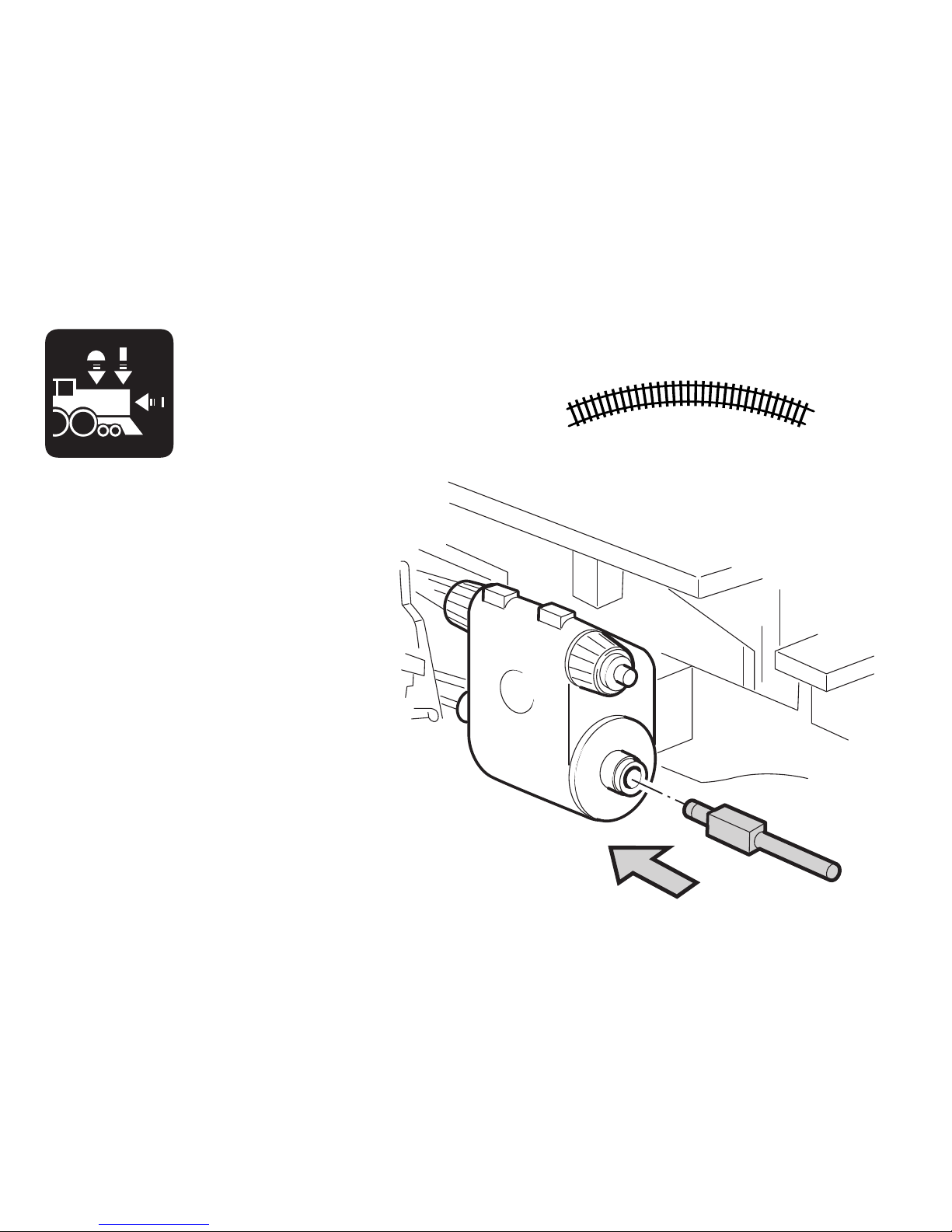
Radius > 500 mm
Page 7
7
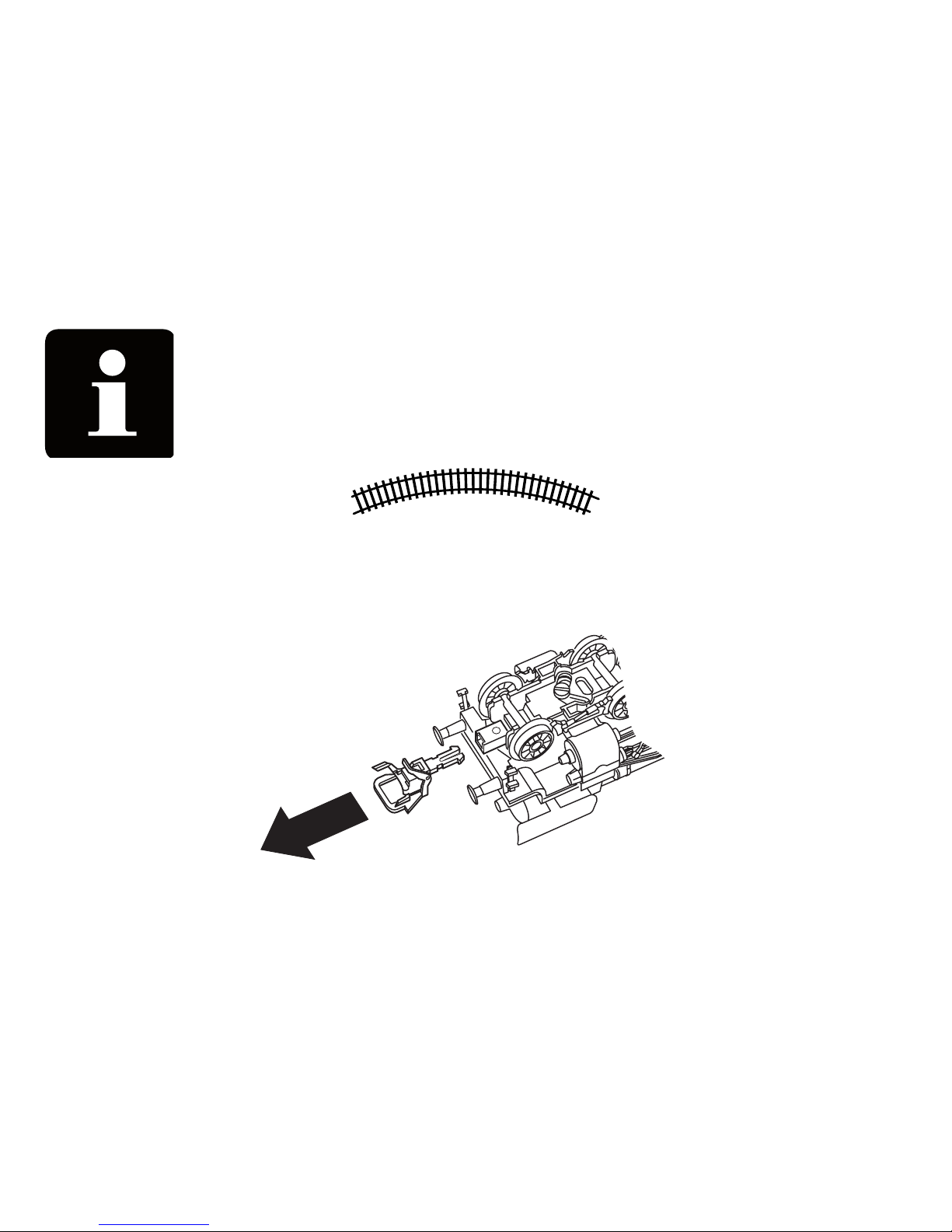
Radius > 500 mm
Page 8

8
Sicherheitshinweise
• Die Lok darf nur mit einem dafür bestimmten Betriebssystem eingesetzt werden.
• Analog max. 15 Volt =, digital max. 22 Volt ~.
• Die Lok darf nur aus als einer Leistungsquelle versorgt
werden.
• Beachten Sie unbedingt die Sicherheitshinweise in der
Bedienungsanleitung zu Ihrem Betriebssystem.
• Für den konventionellen Betrieb der Lok muss das Anschlussgleis entstört werden. Dazu ist das Entstörset
611 655 zu verwenden. Für Digitalbetrieb ist das Entstörset nicht geeignet.
• ACHTUNG! Funktionsbedingte scharfe Kanten und Spitzen.
• Setzen Sie das Modell keiner direkten Sonneneinstrahlung, starken Temperaturschwankungen oder hoher
Luftfeuchtigkeit aus.
Wichtige Hinweise
• Die Bedienungsanleitung und die Verpackung sind
Bestandteile des Produktes und müssen deshalb aufbewahrt sowie bei Weitergabe des Produktes mitgegeben
werden.
• Für Reparaturen oder Ersatzteile wenden Sie sich bitte an
Ihren Trix-Fachhändler.
• Gewährleistung und Garantie gemäß der beiliegenden
Garantieurkunde.
• Entsorgung: www.maerklin.com/en/imprint.html
• Der volle Funktionsumfang ist nur unter Trix Systems,
DCC und unter mfx verfügbar.
• Eingebaute, fahrtrichtungsabhängige Stirnbeleuchtung.
Im Digitalbetrieb schaltbar.
• Befahrbarer Mindestradius 360 mm.
• Rauchsatz nachrüstbar - auch für Analogbetrieb.
Multiprotokollbetrieb
Analogbetrieb
Der Decoder kann auch auf analogen Anlagen oder Gleisabschnitten betrieben werden. Der Decoder erkennt die
analoge Gleichspannung (DC) automatisch und passt sich
der analogen Gleisspannung an. Es sind alle Funktionen,
die unter mfx oder DCC für den Analogbetrieb eingestellt
wurden aktiv (siehe Digitalbetrieb).
Digitalbetrieb
Der Decoder ist ein Multiprotokolldecoder. Der Decoder
kann unter folgenden Digital-Protokollen eingesetzt werden:
mfx oder DCC.
Das Digital-Protokoll mit den meisten Möglichkeiten ist das
höchstwertige Digital-Protokoll. Die Reihenfolge der DigitalProtokolle ist in der Wertung fallend:
Priorität 1: mfx
Priorität 2: DCC
Priorität 3: DC
Hinweis: Werden zwei oder mehrere Digital-Protokolle am
Gleis erkannt, übernimmt der Decoder automatisch das
höchstwertige Digital-Protokoll, z.B. mfx/DCC, somit wird
das mfx-Digital-Protokoll vom Decoder übernommen.
Hinweis: Beachten Sie, dass nicht alle Funktionen in allen
Digital-Protokollen möglich sind. Unter mfx und DCC können
einige Einstellungen von Funktionen, welche im AnalogBetrieb wirksam sein sollen, vorgenommen werden.
Page 9

9
Hinweise zum Digitalbetrieb
• Die genaue Vorgehensweise zum Einstellen der diversen
Parameter entnehmen Sie bitte der Bedienungsanleitung
Ihrer Mehrzug-Zentrale.
• Die ab Werk eingestellten Werte sind für mfx gewählt, so
dass ein bestmöglichstes Fahrverhalten gewährleistet ist.
Für andere Betriebssysteme müssen gegebenenfalls
Anpassungen getätigt werden.
• Der Betrieb mit gegenpoliger Gleichspannung im
Bremsabschnitt ist mit der werkseitigen Einstellung
nicht möglich. Ist diese Eigenschaft gewünscht, so muss
auf den konventionellen Gleichstrombetrieb verzichtet
werden (CV 29/Bit 2 = 0).
mfx-Protokoll
Adressierung
• Keine Adresse erforderlich, jeder Decoder erhält eine
einmalige und eindeutige Kennung (UID).
• Der Decoder meldet sich an einer Central Station oder
Mobile Station mit seiner UID automatisch an.
Programmierung
• Die Eigenschaften können über die grafische Oberfläche
der Central Station bzw. teilweise auch mit der Mobile
Station programmiert werden.
• Es können alle Configuration Variablen (CV) mehrfach
gelesen und programmiert werden.
• Die Programmierung kann entweder auf dem Haupt- oder
dem Programmiergleis erfolgen.
• Die Defaulteinstellungen (Werkseinstellungen) können
wieder hergestellt werden.
• Funktionsmapping: Funktionen können mit Hilfe der
Central Station 60212 (eingeschränkt) und mit der Central
Station 60213/60214/60215 beliebigen Funktionstasten
zugeordnet werden (siehe Hilfe in der Central Station).
DCC-Protokoll
Adressierung
• Kurze Adresse – Lange Adresse – Traktionsadresse
• Adressbereich:
1 – 127 kurze Adresse, Traktionsadresse
1 – 10239 lange Adresse
• Jede Adresse ist manuell programmierbar.
• Kurze oder lange Adresse wird über die CVs ausgewählt.
• Eine angewandte Traktionsadresse deaktiviert die
Standard-Adresse.
Programmierung
• Die Eigenschaften können über die Configurations Variablen (CV) mehrfach geändert werden.
• Die CV-Nummer und die CV-Werte werden direkt eingegeben.
• Die CVs können mehrfach gelesen und programmiert
werden (Programmierung auf dem Programmiergleis).
• Die CVs können beliebig programmiert werden (Programmierung auf dem Hauptgleis PoM). PoM ist nur bei den in
der CV-Tabelle gekennzeichneten CV möglich. Die Programmierung auf dem Hauptgleis (PoM) muss von Ihrer
Zentrale unterstützt werden (siehe Bedienungsanleitung
ihres Gerätes).
• Die Defaulteinstellungen (Werkseinstellungen) können
wieder hergestellt werden.
Page 10

10
• 14 bzw. 28/126 Fahrstufen einstellbar.
• Alle Funktionen können entsprechend dem Funktionsmapping geschaltet werden.
• Weitere Information, siehe CV-Tabelle DCC-Protokoll.
Es wird empfohlen, die Programmierungen grundsätzlich auf
dem Programmiergleis vorzunehmen.
Logische Funktionen
Anfahr-/Bremsverzögerung (ABV)
• Die Beschleunigungs- und Bremszeit kann getrennt von
einander eingestellt werden.
• Die logische Funktionsabschaltung ABV kann über das
Funktionsmapping auf jede beliebige Funktionstaste
gelegt werden.
Page 11
11
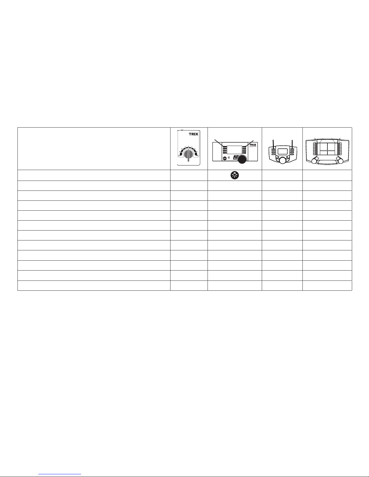
Schaltbare Funktionen
Spitzensignal an Funktion f0 Funktion f0
Rauchgenerator
*
— Funktion 1 Funktion f1 Funktion f1
Betriebsgeräusch — Funktion 2 Funktion f2 Funktion f2
Geräusch: Lokpfeife lang — Funktion 3 Funktion f3 Funktion f3
ABV aus — Funktion 4 Funktion f4 Funktion f4
Geräusch: Bremsenquietschen aus — Funktion 5 Funktion f5 Funktion f5
Geräusch: Glocke
—
Funktion 6 Funktion f6 Funktion f6
Geräusch: Rangierpfiff — Funktion 7 Funktion f7 Funktion f7
Geräusch: Kohle schaufeln — Funktion 8 Funktion f8 Funktion f8
Geräusch: Dampf ablassen — — Funktion f9 Funktion f9
Geräusch: Luftpumpe — — Funktion f10 Funktion f10
Geräusch: Schüttelrost — — Funktion f11 Funktion f11
* gehört nicht zum Lieferumfang
STOP
mobile station
1
5
f0 f8 f0f8
f0 - f3 f4 - f7
Page 12
12
CV Bedeutung Wert DCC ab Werk
1 Adresse 1 - 127 3
2 PoM Minimalgeschwindigkeit 0 - 255 15
3 PoM Anfahrverzögerung 0 - 255 15
4 PoM Bremsverzögerung 0 - 255 15
5 PoM Maximalgeschwindigkeit 0 - 255 255
8 Werkreset/Herstellerkennung 8 131
13 PoM Funktionen F1 - F8 im Analogbetrieb 0 - 255 1
14 PoM Funktionen F9 - F15 und Licht im Analogbetrieb 0 - 255 1
17 Erweiterte Adresse (oberer Teil) CV 29, Bit 5 =1 192
18 Erweiterte Adresse (unterer Teil) CV 29, Bit 5 =1 128
19 Traktionsadresse 0 - 255 0
21 PoM Funktionen F1 - F8 bei Traktion 0 - 255 0
22 PoM Funktionen F9 - F15 und Licht bei Traktion 0 - 255 0
29 PoM
Bit 0: Umpolung Fahrtrichtung
Bit 1: Anzahl Fahrstufen 14 oder 28/128*
Bit 2: DCC Betrieb mit Bremsstrecke (kein Analogbetrieb möglich)
Bit 5: Adressumfang 7 Bit / 14 Bit
0 / 1
0 / 2
0 / 4
0 / 32
***
0, 1, 2, 3, 4, 5, 6,
7, 32, 34, 35, 36,
37, 38, 39
6
63 PoM Lautstärke 0 - 255 255
PoM Program on the Main; muss vom Steuergerät unterstützt werden
* Fahrstufen am Lokdecoder und am Steuergerät müssen übereinstimmen, es sind sonst Fehlfunktionen möglich.
*** Die Werte der gewünschten Einstellungen sind zu addieren!
Page 13

13
travel. They can be turned on and off in digital operation.
• Minimum radius for operation is 360 mm/14-3/16“.
• A smoke generator can be retrofitted to the locomotive also for analog operation.
Multi-Protocol Operation
Analog Operation
This decoder can also be operated on analog layouts or areas of track that are analog. The decoder recognizes alternating current (DC) and automatically adapts to the analog
track voltage. All functions that were set under mfx or DCC
for analog operation are active (see Digital Operation).
Digital Operation
The decoders are multi-protocol decoders. These decoders
can be used under the following digital protocols: mfx or DCC.
The digital protocol with the most possibilities is the highest
order digital protocol. The sequence of digital protocols in
descending order is:
Priority 1: mfx
Priority 2: DCC
Priority 3: DC
Note: If two or more digital protocols are recognized in the
track, the decoder automatically takes on the highest order
digital protocol, example: mfx/DCC; the decoder takes on the
mfx digital protocol (see previous table).
Note: Please note that not all functions are possible in all
digital protocols. Several settings for functions, which are
supposed to be active in analog operation, can be done
under mfx and DCC.
Safety Notes
• This locomotive is only to be used with the operating
system it is designed for.
• Analog max. 15 volts DC, digital max. 22 volts AC.
• This locomotive must never be supplied with power from
more than one power pack.
• Please make note of the safety notes in the instructions
for your operating system.
• The feeder track must be equipped to prevent interference with radio and television reception, when the
locomotive is to be run in conventional operation. The
611 655 interference suppression set is to be used for this
purpose. The interference suppression set is not suitable
for digital operation.
• WARNING! Sharp edges and points required for operation.
• Do not expose the model to direct sunlight, extreme
changes in temperature, or high humidity.
Important Notes
• The operating instructions and the packaging are a component part of the product and must therefore be kept as
well as transferred along with the product to others.
• Please see your authorized Trix dealer for repairs or
spare parts.
• The warranty card included with this product specifies
the warranty conditions.
• Disposing: www.maerklin.com/en/imprint.html
• The full range of functions is only available under Trix
Systems and under DCC.
• Built-in headlights that change over with the direction of
Page 14

14
Notes on digital operation
• The operating instructions for your central unit will give
you exact procedures for setting the different parameters.
• The values set at the factory have been selected for mfx
in order to guarantee the best possible running characteristics.
Adjustments may have to be made for other operating
systems.
• The setting done at the factory does not permit operation
with opposite polarity DC power in the braking block.
If you want this characteristic, you must do without
conventional DC power operation (CV 29/Bit 2 = 0).
mfx Protocol
Addresses
• No address is required; each decoder is given a onetime, unique identifier (UID).
• The decoder automatically registers itself on a Central
Station or a Mobile Station with its UID.
Programming
• The characteristics can be programmed using the
graphic screen on the Central Station or also partially
with the Mobile Station.
• All of the Configuration Variables (CV) can be read and
programmed repeatedly.
• The programming can be done either on the main track or
the programming track.
• The default settings (factory settings) can be produced
repeatedly.
• Function mapping: Functions can be assigned to any of
the function buttons with the help of the 60212 Central
Station (with limitations) and with the 60213/60214/60215
Central Station (See help section in the Central Station).
DCC Protocol
Addresses
• Short address – long address – multiple unit address
• Address range:
1 – 127 for short address and multiple unit address,
1 – 10239 for long address
• Every address can be programmed manually.
• A short or a long address is selected using the CVs.
• A multiple unit address that is being used deactivates the
standard address.
Programming
• The characteristics can be changed repeatedly using the
Configuration Variables (CV).
• The CV numbers and the CV values are entered directly.
• The CVs can be read and programmed repeatedly. (Programming is done on the programming track.)
• The CVs can be programmed in any order desired. (Programming can be done on the main track PoM). The PoM
can only be done with those designated in the CV table.
Programming on the main track PoM must be supported
by your central controller (Please see the description for
this unit.).
• The default settings (factory settings) can be produced
repeatedly.
• 14 or 28/126 speed levels can be set.
Page 15

15
• All of the functions can be controlled according to the
function mapping (see CV description).
• See the CV description for the DCC protocol for additional
information.
We recommend that in general programming should be
done on the programming track.
Logic Functions
Acceleration/Braking Delay (ABV)
• The acceleration and braking time can be set separately
from each other.
• The logic function ABV can be assigned to any function
button by using the function mapping.
Page 16

16
Controllable Functions
Headlights on Function f0 Function f0
Smoke generator * — Function 1 Function f1 Function f1
Locomotive operating sounds — Function 2 Function f2 Function f2
Sound effect: long whistle blast — Function 3 Function f3 Function f3
ABV off — Function 4 Function f4 Function f4
Sound effect: Squealing brakes off — Function 5 Function f5 Function f5
Sound effect: Bell — Function 6 Function f6 Function f6
Sound effect: Short whistle blast — Function 7 Function f7 Function f7
Sound effect: Coal being shoveled — Function 8 Function f8 Function f8
Sound effect: Blowing off steam — — Function f9 Function f9
Sound effect: Air pump — — Function f10 Function f10
Sound effect: Rocker grate — — Function f11 Function f11
* not included in delivery scope
STOP
mobile station
1
5
f0 f8 f0f8
f0 - f3 f4 - f7
Page 17

17
PoM Program on the Main; must be supported by the controller
* The speed levels on the locomotive decoder and on the controller must agree with each other; otherwise,
you may have malfunctions.
*** The values for the desired settings must be added.
CV Discription DCC Value Factory-Set
1 Address 1 - 127 3
2 PoM Minimum Speed 0 - 255 15
3 PoM Acceleration delay 0 - 255 15
4 PoM Braking delay 0 - 255 15
5 PoM Maximum speed 0 - 255 255
8 Factory Reset / Manufacturer Recognition 8 131
13 PoM Functions F1 - F8 in analog operation 0 - 255 1
14 PoM Functions F9 - F15 and lights in analog operation 0 - 255 1
17 Extended address (upper part) CV 29, Bit 5 =1 192
18 Extended address (lower part) CV 29, Bit 5 =1 128
19 Multiple Unit Address 0 - 255 0
21 PoM Functions F1 - F8 on Multiple Unit 0 - 255 0
22 PoM Functions F9 - F15 and lights on Multiple Unit 0 - 255 0
29 PoM
Bit 0: Reversing direction
Bit 1: Number of speed levels 14 or 28/128*
Bit 2: DCC operation with braking area
(no analog operation possible)
Bit 5: Address length 7 Bit / 14 Bit
0 / 1
0 / 2
0 / 4
0 / 32
***
0, 1, 2, 3, 4, 5, 6,
7, 32, 34, 35, 36,
37, 38, 39
6
63 PoM Volume 0 - 255 255
Page 18

18
Remarques importantes sur la sécurité
• La locomotive ne peut être utilisée qu‘avec le système
d‘exploitation indiqué.
• Analogique max. 15 Volt =, digital max. 22 Volt ~.
• La locomotive ne peut pas être alimentée électriquement
par plus d‘une source de courant à la fois.
• Il est impératif de tenir compte des remarques sur la
sécurité décrites dans le mode d‘emploi de votre système
d‘exploitation.
•
Pour l’exploitation de la locomotive en mode conventionnel, la voie de raccordement doit être déparasitée. A
cet effet, utiliser le set de déparasitage réf. 611 655. Le set
de déparasitage ne convient pas pour l’exploitation en
mode numérique.
•
ATTENTION! Pointes et bords coupants lors du fonctionnement du produit.
• Ne pas exposer le modèle à un ensoleillement direct,
à de fortes variations de température ou à un taux
d‘humidité important.
Information importante
• La notice d‘utilisation et l’emballage font partie intégrante
du produit ; ils doivent donc être conservés et, le cas
échéant, transmis avec le produit.
• Pour toute réparation ou remplacement de pièces,
adressez vous à votre détaillant-spécialiste Trix.
• Garantie légale et garantie contractuelle conformément
au certificat de garantie ci-joint.
• Elimination : www.maerklin.com/en/imprint.html
• L’intégralité des fonctions est disponible uniquement en
exploitation Trix Systems, DCC et mfx.
• Feux de signalisation s‘inversant selon le sens de marche; feux commutables en exploitation digital.
• Rayon minimal d’inscription en courbe 360 mm.
• Installation ultérieure d’un générateur de fumée possible
- également pour exploitation analogique.
Mode multiprotocole
Mode analogique
On peut aussi faire fonctionner le décodeur sur des installations ou des sections de voie analogiques. Le décodeur
identifie automatiquement la tension de voie analogique (CC).
Toutes les fonctions qui ont été paramétrée pour le mode
analogique sous mfx ou sous DCC sont actives (voir mode
numérique).
Mode numérique
Les décodeur sont des décodeur multiprotocole. Le
décodeur peut être utilisé avec les protocoles numériques
suivants : mfx, DCC
Le protocole numérique offrant les possibilités les plus
nombreuses est le protocole numérique à bit de poids
fort. La hiérarchisation des protocoles numériques est
descendante :
Priorité 1 : mfx
Priorité 2 : DCC
Priorité 3 :
DC
Indication : Lorsque deux ou plusieurs protocoles numériques sont identifiés au niveau de la voie, le décodeur
reprend automatiquement le protocole numérique à bit de
Page 19

19
poids fort, p. ex. mfx/DCC. Le protocole numérique mfx est
donc repris par le décodeur (voir tableau antérieur).
Indication : remarquez que toutes les fonctions ne peuvent
pas être actionnées dans tous les protocoles numériques.
Sous mfx et sous DCC, il est possible de procéder à
quelques paramétrages de fonctions devant être actives
dans le cadre de l’exploitation analogique.
Remarques relatives au fonctionnement
en mode digital
• En ce qui concerne la procédure de réglage des divers
paramètres, veuillez vous référer au mode d‘emploi de
votre centrale de commande multitrain.
• Les valeurs paramétrées d’usine sont choisies pour
mfx de manière à garantir le meilleur comportement de
roulement possible.
Pour d’autres systèmes d’exploitation, ces valeurs
devront éventuellement être adaptées.
• L’exploitation avec courant continu de polarité inverse
dans les sections de freinage n’est pas possible avec
le réglage d’usine. Si cette propriété est désirée, il faut
alors renoncer à l’exploitation conventionnelle en courant continu (CV 29/Bit 2 = 0).
Protocole mfx
Adressage
• Aucune adresse n’est nécessaire, le décodeur reçoit toutefois une identification unique et non équivoque (UID).
• Avec son UID, le décodeur indique automatiquement
à une station centrale ou à une station mobile qu’il est
connecté.
Programmation
• Les caractéristiques peuvent être programmées par
l’intermédiaire de la couche graphique de la station centrale, voire en partie aussi au moyen de la station mobile.
• Toutes les configurations variables (CV) peuvent être lues
et programmées de façon réitérée.
• La programmation peut être réalisée soit sur la voie
principale, soit sur la voie de programmation.
• Les paramétrages par défaut (paramétrages usine)
peuvent être rétablis.
• Mappage des fonctions : les fonctions peuvent être
affectées à de quelconques touches de fonction au
moyen de la station centrale (60212) (restreinte) et avec
la station centrale 60213/60214/60215 (voir Aide au niveau
de la station centrale).
Protocole DCC
Adressage
• Adresse brève – adresse longue – adresse de traction.
• Champ d’adresse :
1 – 127 adresse brève, adresse de traction
1 – 10239 adresse longue
• Chaque adresse est programmable manuellement.
• L’adresse brève ou longue est choisie par l’intermédiaire
des CVs.
• Une adresse de traction utilisée désactive l’adresse
standard.
Programmation
• Les caractéristiques peuvent être modifiées de façon
Page 20

20
réitérée par l’intermédiaire des variables de configuration
(CVs).
• Toutes les configurations variables (CV) peuvent être lues
et programmées de façon réitérée.
• La programmation peut être réalisée soit sur la voie
principale, soit sur la voie de programmation.
• Les CVs peuvent être programmées librement (programmation de la voie principale (PoM). La PoM n’est
possible que pour les CVs identifiées dans le tableau des
CVs. La programmation sur la voie principale (PoM) doit
être supportée par votre centrale (voir mode d’emploi de
votre appareil).
• Les paramétrages par défaut (paramétrages usine)
peuvent être rétablis.
• 14, voire 28/126 crans de marche sont paramétrables.
• Toutes les fonctions peuvent être commutées en fonction
du mappage des fonctions (voir le descriptif des CVs).
• Pour toute information complémentaire, voir le tableau
des CVs, protocole DCC.
Il est recommandé, de réaliser la programmation, fondamentalement, sur la voie de programmation.
Fonctions logiques
Retard au démarrage / au freinage (ABV)
• Les temps d’accélération et de freinage peuvent être
paramétrés séparément les uns des autres.
• Par l’intermédiaire du mappage des fonctions, la mise
hors fonction de la fonction logique ABV peut être affectée à n’importe quelle touche de fonction.
Page 21

21
Fonctions commutables
Fanal éclairage activé Fonction f0 Fonction f0
Générateur de fumée * — Fonction 1 Fonction f1 Fonction f1
Bruitage : Échappement de la vapeur — Fonction 2 Fonction f2 Fonction f2
Bruitage : Sifflet longueur — Fonction 3 Fonction f3 Fonction f3
ABV, désactivé — Fonction 4 Fonction f4 Fonction f4
Bruitage : Grincement de freins désactivé — Fonction 5 Fonction f5 Fonction f5
Bruitage : Cloche — Fonction 6 Fonction f6 Fonction f6
Bruitage : Sifflet pour manœuvre — Fonction7 Fonction f7 Fonction f7
Bruitage : Pelletage du charbon — Fonction 8 Fonction f8 Fonction f8
Bruitage : Échappement de la vapeur — — Fonction f9 Fonction f9
Bruitage : Compresseur — — Fonction f10 Fonction f10
Bruitage : Grille à secousses — — Fonction f11 Fonction f11
* ne fait pas partie de la fourniture
STOP
mobile station
1
5
f0 f8 f0f8
f0 - f3 f4 - f7
Page 22

22
CV Affectation DCC Valeur Parm. Usine
1 Adresse 1 - 127 3
2 PoM Vitesse minimale 0 - 255 15
3 PoM Temporisation d‘accélération 0 - 255 15
4 PoM Temporisation de freinage 0 - 255 15
5 PoM Vitesse maximale 0 - 255 255
8 Réinitialisation d’usine/identification du fabricant 8 131
13 PoM Fonctions F1 - F8 en mode analogique 0 - 255 1
14 PoM Fonctions F9 - F15 et éclairage en mode analogique 0 - 255 1
17 Adresse étendue (partie supérieure) CV 29, Bit 5 =1 192
18 Adresse étendue (partie inférieure) CV 29, Bit 5 =1 128
19 Adresse traction 0 - 255 0
21 PoM Fonctions F1 - F8 pour traction 0 - 255 0
22 PoM Fonctions F9 - F15 et éclairage traction 0 - 255 0
29 PoM
Bit 0: Inv. polarité Sens de marche
Bit 1: Nombre de crans de marche 14 ou 28/128*
Bit 2:
Mode DCC avec dist. de freinage
(pas possible en mode analogique)
Bit 5: Capacité d’adresses 7 Bit / 14 Bit
0 / 1
0 / 2
0 / 4
0 / 32
***
0, 1, 2, 3, 4, 5, 6,
7, 32, 34, 35, 36,
37, 38, 39
6
63 PoM Volume 0 - 255 255
PoM Program on the Main; doit être pris en charge par l’appareil de commande
* Pour éviter tout dysfonctionnement, les crans de marche sur le décodeur de loco doivent impérativement
coïncider avec ceux de l’appareil de commande.
*** Les valeurs des réglages désirés sont à additioner.
Page 23

23
Veiligheidsvoorschriften
• De loc mag alleen met een daarvoor bestemd bedrijfssysteem gebruikt worden.
• Analoog max. 15 Volt =, digitaal max. 22 Volt ~.
• De loc mag niet vanuit meer dan één stroomvoorziening
gelijktijdig gevoed worden.
• Lees ook aandachtig de veiligheidsvoorschriften in de
gebruiksaanwijzing van uw bedrijfssysteem.
• Voor het conventionele bedrijf met de loc dient de
aansluitrail te worden ontstoort. Hiervoor dient men de
ontstoor-set 611 655 te gebruiken. Voor het digitale bedrijf
is deze ontstoor-set niet geschikt.
• OPGEPAST! Functionele scherpe kanten en punten.
• Stel het model niet bloot aan in directe zonnestraling,
sterke temperatuurwisselingen of hoge luchtvochtigheid.
Belangrijke aanwijzing
• De gebruiksaanwijzing en de verpakking zijn een bestanddeel van het product en dienen derhalve bewaard
en meegeleverd te worden bij het doorgeven van het
product.
• Voor reparaties en onderdelen kunt zich tot Uw Trix
handelaar wenden.
• Vrijwaring en garantie overeenkomstig het bijgevoegde
garantiebewijs.
• Afdanken:www.maerklin.com/en/imprint.html
• De volledige toegang tot alle functies is alleen mogelijk
met Trix Systems, DCC of met mfx bedrijf.
• Ingebouwde, rijrichtingsafhankelijke frontverlichting is in
het digitaalsysteem schakelbaar.
• Minimale te berijden radius: 360 mm.
• Rookgenerator nadien in te bouwen - ook voor analoog
bedrijf.
Multiprotocolbedrijf
Analoogbedrijf
De decoder kan ook op analoge modelbanen of spoortrajecten gebruikt worden. De decoder herkent de analoge
gelijkspanning (DC) automatisch en past zich aan de
analoge railspanning aan. Alle functies die onder mfx of DCC
voor het analoge bedrijf zijn ingesteld, worden geactiveerd
(zie digitaalbedrijf).
Digitaalbedrijf
De Decoder is een multiprotocoldecoder. De decoder kan
onder de volgende digitale protocollen ingezet worden: mfx,
DCC.
Het digitaalprotocol met de meeste mogelijkheden is het
primaire digitaalprotocol. De volgorde van de digitaalprotocollen is afnemend in mogelijkheden:
Prioriteit 1: mfx
Prioriteit 2: DCC
Prioriteit 3: DC
Opmerking: Worden twee of meer digitaal protocollen op
de rails herkend, dan neemt de decoder automatisch het
protocol met de hoogste prioriteit, bijv. mfx/DCC, dan wordt
door de decoder het mfx-digitaalprotocol gebruikt (zie
bovenstaand overzicht).
Opmerking: let er op dat niet alle functies in alle digitaalprotocollen mogelijk zijn. Onder mfx of DCC kunnen enkele
Page 24

24
instellingen, welke in analoogbedrijf werkzaam moeten zijn,
ingesteld worden.
Aanwijzingen voor digitale besturing
• Het op de juiste wijze instellen van de diverse parameters staat beschreven in de handleiding van uw digitale
Centrale.
• Fabrieksmatig zijn de waarden voor mfx zo ingestelt dat
optimale rijeigenschappen gegarandeerd zijn.
Voor andere bedrijfssystemen moeten eventueel aanpassingen uitgevoerd worden.
• Het bedrijf met tegengepoolde gelijkspanning in de afremsectie is met de fabrieksinstelling niet mogelijk. Indien deze
eigenschap wenselijk is, dan moet worden afgezien van
het conventioneel gelijkstroombedrijf (CV 29/Bit 2 = 0).
mfx-protocol
Adressering
• Een adres is niet nodig, elke decoder heeft een éénmalig
en éénduidig kenmerk (UID).
• De decoder meldt zich vanzelf aan bij het Central Station
of Mobile Station met zijn UID.
Programmering
• De eigenschappen kunnen m.b.v. het grafische scherm
op het Central Station resp. deels ook met het Mobile
Station geprogrammeerd worden.
• Alle configuratie variabelen (CV) kunnen vaker gelezen
en geprogrammeerd worden.
• De programmering kan zowel op het hoofdspoor als op
het programmeerspoor gebeuren.
• De default-instellingen (fabrieksinstelling) kunnen weer
hersteld worden.
• Functiemapping: functies kunnen met behulp van het
Central Station 60212 (met beperking) en met het
Central Station 60213/60214/60215 aan elke gewenste
functietoets worden toegewezen (zie het helpbestand in
het Central Station).
DCC-protocol
Adressering
• Kort adres – lang adres – tractie adres
• Adresbereik:
1 – 127 kort adres, tractie adres
1 – 10239 lang adres
• Elk adres is handmatig programmeerbaar.
• Kort of lang adres wordt via de CV gekozen.
• Een toegepast tractieadres deactiveert het standaardadres.
Programmering
• De eigenschappen van de decoder kunnen via de configuratie variabelen (CV) vaker gewijzigd worden.
• De CV-nummers en de CV-waarden worden direct ingevoerd.
• De CV’s kunnen vaker gelezen en geprogrammeerd
worden (programmering op het programmeerspoor).
• De CV’s kunnen naar wens geprogrammeerd worden
(programmering op het hoofdspoor PoM). PoM is alleen
bij de in de CV-tabel aangegeven CV’s mogelijk. De
programmering op het hoofdspoor (PoM) moet door uw
centrale ondersteund worden (zie de gebruiksaanwijzing
Page 25

25
van uw apparaat).
• De default-instellingen (fabrieksinstelling) kunnen weer
hersteld worden.
• 14 resp. 28/126 rijstappen instelbaar.
• Alle functies kunnen overeenkomstig de functiemapping
geschakeld worden (zie CV-beschrijving).
• Voor verdere informatie, zie de CV-tabel DCC-protocol.
Het is aan te bevelen om het programmeren alleen op het
programmeerspoor uit te voeren.
Fysieke functies
Optrek en afremvertraging (ABV)
• De optrek- en afremvertraging kunnen onafhankelijk van
elkaar ingesteld worden.
• De logische uitschakelfunctie ABV (optrek- en afremvertraging) kan met de functiemapping aan elke gewenste
functietoets toegewezen worden.
Page 26

26
Schakelbare functies
Frontverlichting aan Functie f0 Functie f0
Rookgenerator * — Functie 1 Functie f1 Functie f1
Rijgeluiden — Functie 2 Functie f2 Functie f2
Geluid: fluit lang — Functie 3 Functie f3 Functie f3
ABV uit — Functie 4 Functie f4 Functie f4
Geluid: piepende remmen uit — Functie 5 Functie f5 Functie f5
Geluid: luidklok — Functie 6 Functie f6 Functie f6
Geluid: fluit kort — Functie 7 Functie f7 Functie f7
Geluid: kolenscheppen — Functie 8 Functie f8 Functie f8
Geluid: stoom afblazen — — Functie f9 Functie f9
Geluid: luchtpomp — — Functie f10 Functie f10
Geluid: schudrooster — — Functie f11 Functie f11
* maakt geen deel uit van het leveringspakket
STOP
mobile station
1
5
f0 f8 f0f8
f0 - f3 f4 - f7
Page 27

27
PoM Program on the Main; dient door het besturingsapparaat ondersteunt te worden.
* De rijstappen instelling op de decoder en het besturingsapparaat moeten met elkaar overeenkomen anders
kunnen er storingen optreden.
*** De waarde van de gewenste instellingen moeten bij elkaar opgeteld worden.
CV Betekenis Waarde DCC Af fabriek
1 Adres 1 - 127 3
2 PoM Minimale snelheid 0 - 255 15
3 PoM Optrekvertraging 0 - 255 15
4 PoM Afremvertraging 0 - 255 15
5 PoM Maximumsnelheid 0 - 255 255
8 Fabrieksinstelling/fabriekherkenning 8 131
13 PoM functies F1 - F8 in analoogbedrijf 0 - 255 1
14 PoM functies F9 - F15 en licht in analoogbedrijf 0 - 255 1
17 Uitgebreld adres (bovenste gedeelte) CV 29, Bit 5 =1 192
18 Uitgebreld adres (onderste gedeelte) CV 29, Bit 5 =1 128
19 tractieadres 0 - 255 0
21 PoM functies F1 - F8 in tractie 0 - 255 0
22 PoM functies F9 - F15 en licht in tractie 0 - 255 0
29 PoM
Bit 0: ompolen rijrichting
Bit 1: aantal rijstappen 14 of 28/128*
Bit 2: DCC bedrijf met afremtraject (geen analoogbedrijf mogelijk)
Bit 5: adresomvang 7 Bit / 14 Bit
0 / 1
0 / 2
0 / 4
0 / 32
***
0, 1, 2, 3, 4, 5, 6,
7, 32, 34, 35, 36,
37, 38, 39
6
63 PoM Volume 0 - 255 255
Page 28

28
72270
1.
1.
2x
2.
3.
Page 29

29
Potentielle Fehlerquellen beim Rauchgenerator
• Der Rauchgenerator darf nur maximal halb mit Rauchöl
gefüllt sein.
• Im Rauchgenerator darf sich keine Luftblase befinden.
• Der Anschlussdraht an der Unterseite des Rauchgenerators muss sicheren Kontakt zur Anschlussfeder im
Lokomotiv-Fahrgestell besitzen. Notfalls Anschlussdraht
entsprechend nebenstehender Zeichnung justieren.
Potential Problems with the Smoke Generator
• The smoke generator cannot be filled any more than
halfway with smoke fluid.
•
There should not be any air bubbles in the smoke generator
.
• The connecting wire on the underside of the smoke
generator must have a clean contact with the connection
field in the locomotive’s frame. When necessary, adjust
the connecting wire according to the diagram next to this
text.
Causes d‘erreurs potentielles Avec le générateur fumigène
• Le générateur fumigène ne peut pas être rempli de
liquide fumigène au-delà de la moitié du tube.
• Aucune bulle d‘air ne peut se trouver dans le générateur
fumigène.
• Le câble de raccordement raccordé à la face inférieure
du fumigène doit posséder un contact sûr avec le ressort
de connexion dans le châssis de la locomotive. En cas
de besoin, ajustez le câble de connexion en vous conformant au schéma.
Potentiële storingsoorzaken bij rookgeneratoren
• De rookgenerator mag maximaal half met rookolie gevuld
worden.
• In de rookgenerator mag zich geen luchtbel bevinden.
• De aansluitdraad aan de onderzijde van de rookgenerator
moet een betrouwbaar contact maken met de contactveer in het locomotief onderstel. Eventueel de aansluitdraad volgens de onderstaande tekening bijstellen.
Page 30

30
1.
1.
2x
2.
2.
1.
Page 31

31
1.
2x
2.
!
Page 32

32
Page 33

33
1 .
2 .
2 .
3 .
4.
Page 34

34
40h
Page 35

35
Page 36

36
Details der Darstel-
lung können von dem
Modell abweichen.
3
3
3
3
3
3
8
3
3
4
4
1
8
8
9
9
9
8
9
1
1
5
5
2
6
2
7
31
6
18
21
16
10
11
14
12
13
14
11
12
13
15
17
17
16
20
6
19
6
24
25
23
22
9
Page 37

37
28
26
29
6
15
26
33
32
32
35
34
22
30
27
Details der Darstel-
lung können von dem
Modell abweichen.
Page 38

38
1 Fenster E186 462
2 Windleitbleche E186 464
3 Rohre u. Leitungen E223 707
4 Handrad E282 220
5 Motor mit Getriebe E180 687
6 Schraube E786 790
7 Umlauf / Laternen E237 345
8 Behälter E186 467
9 Steckteile Kessel E186 468
10 Haftreifen 7 153
11 Distanzring E191 466
12 Mutter E499 830
13 Schraube E191 468
14 Schraube E224 995
15 Puffer E121 629
Puffer E761 850
16 Gestänge links E219 785
17 Gestänge rechts E219 774
18 Schraube E785 090
19 Schraube E785 200
20 Bremsattrappe E219 798
21 Zugstange E180 973
22 Kurzkupplung E701 630
23 Schraube E753 000
24 Schleifer E225 596
25 Drehgestell E250 641
26 Lautsprecher m. Resonator E183 288
27 Decoder 249 519
28 Leiterplatte Beleuchtung E182 628
29 Schraube E786 540
30 Halteplatte E405 040
31 Druckfeder E15 2097 00
32 Drehgestellrahmen E434 100
33 Kupplungsdeichsel E215 804
34 Schraube E786 560
35 Schleiferfeder E434 110
Bremsleitung E12 5149 00
Schraubenkupplung E282 310
Kolbenstangenschutzrohr E445 900
Schienenräumer E180 980
Hinweis: Einige Teile werden nur ohne oder mit anderer
Farbgebung angeboten.
Teile, die hier nicht aufgeführt sind, können nur im Rahmen
einer Reparatur im Märklin-Reparatur-Service repariert
werden.
Page 39

39
Page 40

Gebr. Märklin & Cie. GmbH
Stuttgarter Straße 55 - 57
73033 Göppingen
Germany
www.trix.de
250386/1214/Kd1Ef
Änderungen vorbehalten
© Gebr. Märklin & Cie. GmbH
www.maerklin.com/en/imprint.html
Due to different legal requirements regarding electro-magnetic compatibility,
this item may be used in the USA only after separate certification for FCC compliance and an adjustment if necessary.
Use in the USA without this certification is not permitted and absolves us of any
liability. If you should want such certification to be done, please contact us –
also due to the additional costs incurred for this.
 Loading...