

Page 1
INSTRUCTION HANDBOOK
LP 218
Laser Printer 300 Series
Page 2

Foreword
Safety Information
Laser Safety
This is a page printer which operates by means of a laser. There is no
possibility of danger from the laser, provided the printer is operated
according to the instructions in this manual.
Since radiation emitted by the laser is completely confined within protective housing,the laser beam cannot escape from the machine during
any phase of user operation.
Internal Laser Radiation
Maximum Radiation Power:
1.03 mW at laser aperture of the print head unit
Wavelength:
770–810 nm
This product employs Class IIIb Laser Diode that emits an invisible
laser bea m.
Laser Diode and Scanning Polygon Mirror are incorporated in the print
head unit.
The print head unit is not a field service item.
Therefore, the print head unit should not be opened under any circum-
stance.
Laser Safety
This printer is certified as a Class I Laser product under the U.S.
Department of Health and Human Services (DHHS) Radiation Per-
formance Standard according to the Radiation Control for Health and
Safety Act of 1968. This m eans that the printer does not produce hazardous laser radiation.
i
Page 3
Foreword
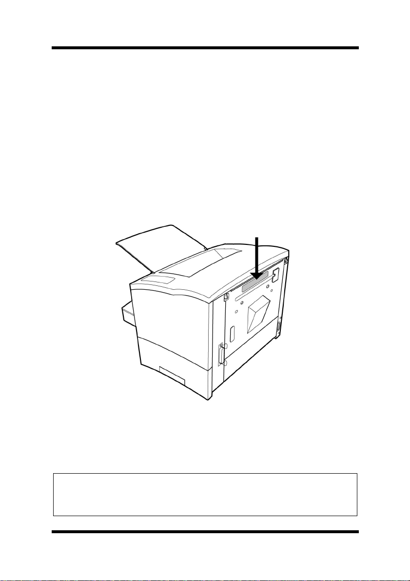
CDRH Regulations
The Center for Devices and Radiological Health (CDRH) of the
U.S. Food and Drug Administration implemented regulations for laser
products on A ugust 2, 1976. Compliance is mandatory for products
marketed in the United States. The label shown below indicates compliance with the C DRH regulations and m ust be a ttached to laser products m arketed in the United States.
Laser Safety Label
Caution
◆ Use of controls, adjustments or performance of procedures other
than those specified in this manual may result in hazardous radiation exposure.
ii
Page 4
Foreword
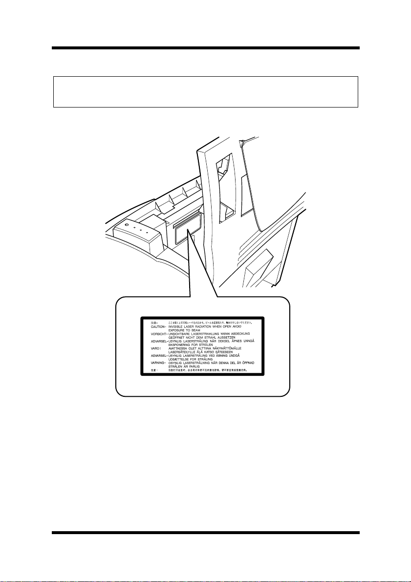
Caution
◆ This is a semiconductor laser. The maximum power of the laser
diode is 5 mW and the wavelength is 770–810 nm.
Laser Caution Label
iii
Page 5

Foreword
User Instructions
FCC Part 15 - Radio Frequency Devices Warning (for U.S.A. Users)
FCC: Declaration of Conformity
Product Type Laser Beam Prin ter
Product
Name
Options Second Paper Cas s ette Unit
This device complies with Part 15 of the FCC Rules.
Operation is subj ec t to the following condi tions ;
1. this device may not cause harmful interference, and
2. this device must accept any interference received, including
interference that ma y cause undesired operation.
Laser Printer 300 Series
Third Paper Cassette Unit
Duplex Unit
Expansion memory (Maximum 96MB )
iv
Page 6

Foreword
This equipment has been tested and found to comply with the limits for
a Class B digital device, pursuant to Part 15 of the FCC Rules. These
limits are designed to provide reasonable protection against harmful
interference in a residential installation. This equipment generates,
uses a nd ca n radiate radio frequency energy and, if not installed and
used in accordance with the instructions, may cause harmful interference to radio communications. However, there is no guarantee that
interferencewill not occur in a particular installation. If this equipment
does cause harmful interference to radio or television reception, which
can be determined by turning the equipment off and on, the user is
encouraged to try to correct the interface by one or more of the following measures:
• Reorient or relocate t he receiving antenna.
• Increase the separation between the equipment and the
receiver.
• Connect the equipment into an outlet on a circuit different from
that to which the receiver is connected.
• Consult the dealer or an experienced radio/TV technician for
help.
This device m ust be used with a shielded interface cable and shielded
network cable. The use of non-shield cables is likely to result in interference with radio communications and is prohibited under FCC rules.
The design and production of this unit conform to FCC regulations,
and any changes or m odifications must be registered with the FCC and
are subject to FCC control. Any changes made by the purchaser or user
without first contacting the manufacturer will be subject to penalty
under FCC regulations.
v
Page 7

Foreword
Warning
◆ The design and production of this unit conform to FCC regulations,
and any changes or modifications must be registered with the FCC
and are subject to FCC control.
◆ Any changes made by the purchaser or user without first contacting
the manufa cturer will be subject to penalty under FCC regulations.
Interference-Causing Equipment Standard (ICES-003 ISSUE 3) Warning (for Canada Users)
This Class B digital apparatus complies with Canadian ICES-003.
Cet appareil numérique de la classe B est conforme à la norme NMB-
003 du Canada.
This Class A digital apparatus (4179-261) complies with Canadian
ICES-003.
Cet appareil numérique de la classe A (4179-261) est conforme à la
norme NMB-003 du Canada.
Ozone Release
During printer operation, a small quantity of ozone is released. This
amount is not large enough to harm anyone adversely. However, be
sure the room where the machine is being used has adequate ventilation, especially if you are printing a high volume of materials, or if the
machine is being used c ontinuously over a long period.
vi
Page 8

Foreword
Welcome
And thank you for selecting a Laser Printer 300 Series Printer!
This User’s Manual explains the functions of the printer and how it
operates. It also provides you with troubleshooting tips as well as general precautions you should observe when operating the printer. To
ensure the top pe rformance and effective use of your printer, read this
manual c arefully from cover to cover, and keep it at hand for later reference.
The contents of this manual are subject to change without notice.
Should there be any discrepancy between the printed materials and the
electronic-based resources provided with your printer, please refer to
the printed ma terials as your primary resource.
Trademark Acknowledgments
PCL is a registered trademark of Hewlett-Packard Company.
Centronics is a registered trademark of Centronics Inc.
Microsoft, Windows, and Windows NT are registered trademarks of
Microsoft Corporation.
All other brand or product names are trademarks or registered trade-
marks of their r espective companies or organizations.
vii
Page 9

Foreword
viii
Page 10

Contents
Laser Safety......................................................i
Ozone Release ...............................................vi
Trademark Acknowledgments........................vii
Introduction..........................................................1--1
Operating System ........................................1-1
Indicators......................................................1-5
Panel Button................................................. 1-6
Setting-Up.............................................................2--1
Selecting a Location for the Printer..............2-1
Operating Environment................................2-5
Printer...........................................................2-5
Printer Supplies............................................ 2-7
Unpacking the Printer................................... 2-8
Installing the Face-Down Tray....................2-10
Installing Tray 1.......................................... 2-11
Connecting the Power Cord....................... 2-12
Second/Third Paper Cassette Unit.............2-20
Expansion Memory ....................................2-30
Using the Printer..................................................3--1
Print Configuration Page..............................3-1
Form Feed.................................................... 3-1
Type.............................................................3-2
Paper Type................................................. 3-18
Paper Size.................................................. 3-18
viii
Page 11

Contents
PCL Printer Driver................................................4--1
Introduction......................................................4-1
System Requirements..................................... 4-2
Installing the USB Device Driver for the Laser
Printer 300 Series............................................ 4-3
To Installthe USB Device Driver Under Windows
98.................................................................4-3
To Installthe USB Device Driver Under Windows
Me................................................................4-6
To Installthe USB Device Driver Under Windows
2000.............................................................4-9
Installing the PCL Printer Dr iver Under Windows
95.....................................................................4-17
To Install the PCL Printer Driver Using Plug-and-
Play............................................................4-17
To Install the PCL Printer Driver Using the Add
Printer Wizard ............................................ 4-19
Installing the PCL Printer Dr iver Under Windows
98/Windows Me..............................................4-21
To Install the PCL Printer Driver Using Plug-and-
Play Under Windows 98.............................4-21
To Install the PCL Printer Driver Using Plug-and-
Play Under Windows Me............................4-23
To Install the PCL Printer Driver Using the Add
Printer Wizard ............................................ 4-25
Installing the PCL Printer Dr iver Under Windows
NT 4.0.............................................................. 4-27
ix
Page 12

Contents
To Install the PCL Printer Driver Using the Add
Printer Wizard ............................................ 4-27
Installing the PCL Printer Dr iver Under Windows
2000.................................................................4-30
To Install the PCL Printer Driver Using Plug-and-
Play............................................................4-30
To Install the PCL Printer Driver Using the Add
Printer Wizard ............................................ 4-33
Installing the Laser Printer 300 Series Utilities436
Using the PCL Printer Driver........................ 4-38
Displaying the PCL Printer Driver Setup Dialog
4-38
Common Buttons .......................................4-42
Setup.......................................................... 4-43
Paper..........................................................4-51
Quality........................................................ 4-55
Device Options Setting...............................4-58
Using the Status Display...............................4-59
Starting Up the Status Display....................4-59
Using the Status Display ............................ 4-61
Using the Control Panel................................4-63
Starting Up the Control Panel.....................4-63
Using the Control Panel.............................4-65
Uninstalling the PCL Printer Driver ............. 4-72
x
Page 13

Contents
To Uninstall the PCL Printer Driver ............ 4-72
Uninstalling the Laser Printer 300 Series Utilities
4-76
To Uninstall the Laser Printer 300 Series Utilities
4-76
Uninstalling the USB Device Driver.............4-80
To Uninstall the USB Device Driver............ 4-80
Maintenance.........................................................5--1
To Replace the Imaging Cartridge................5-2
Cleaning the Outside of the Printer..............5-8
Cleaning the Paper Feed Roller...................5-9
Troubleshooting...................................................6--1
Clearing a Paper Misfeed................................ 6-1
Inside the Printer..........................................6-1
Face-Down Tray...........................................6-6
Tray 1...........................................................6-6
Manual Feed Tray........................................6-8
Second/Third Paper Cassette Unit (Option). 6-9
Duplex Unit (Option)................................... 6-10
Print Quality Problems.................................. 6-12
No Output................................................... 6-17
USB Connection Problems...........................6-19
Is the computer equipped with a system that
enables USB connections?........................ 6-19
xi
Page 14

Contents
Was the computer correctly set up?...........6-20
Indicator Lights (Printer Messages) ............6-30
Indicator Light Patterns..............................6-30
Specifications.......................................................7--1
Parallel Interface..........................................7-7
xii
Page 15

Contents
xiii
Page 16

MEMO
Page 17

Contents
xv
Page 18

1Chapter
Introduction
Chapter 1Introduction
1
Page 19

Chapter 1Introduction
Page 20

Features
Features
The various features listed below make the Laser Printer 300 Series the
powerful printer for any size office.
• Fast 18-page-per-minute print speed for quick output
• 1200 × 600 dpi resolution for superior print quality
• PCL 6 emulation for powerful printer language support
• 66 MHz R ISC processor for high-performance printing
• 8 MB of memory (standard)
• USB interface built in
Operating System
• Windows 95
• Windows 98
• Windows M e
• Windows NT 4.0
• Windows 2000
Chapter 1Introduction
1-1
Page 21
Printer Parts and Accessories
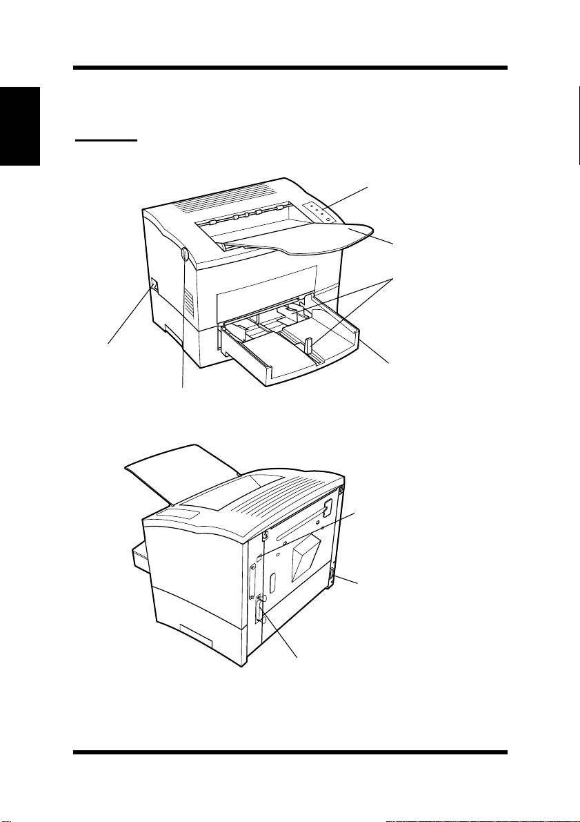
Printer Parts and Accessories
Printer
Chapter 1Introduction
Control panel
Face-down tray
Paper guide
Power switch
Tray 1
Top cover release button
(Multipurpose t ray )
1-2
USB interface
connector
Power cord socket
Parallel interface
connector
Page 22
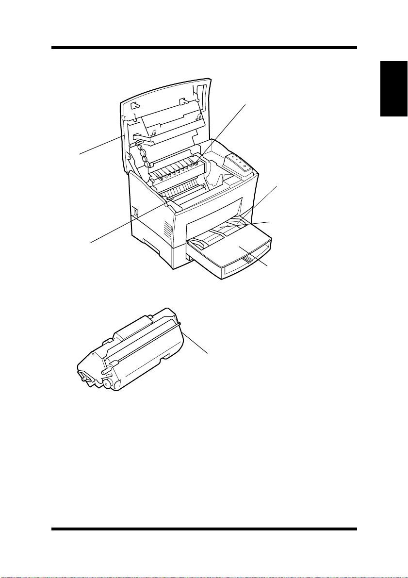
Printer Parts and Accessories
Top cover
Image transfer
roller
Fusing unit
Manual feed tray
Tray cover
Imaging cartridge
Chapter 1Introduction
Paper guide
1-3
Page 23
Printer Parts and Accessories
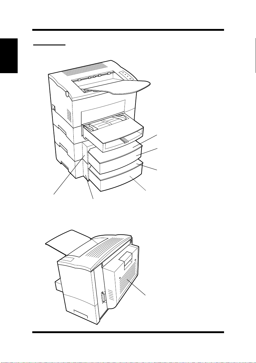
Options
Chapter 1Introduction
Cassette cover
Tray 2 (500-sheet
second cassette)
Cassette cover
Tray 3 (500-sheet
Second paper
cassette unit
Third paper
cassette unit
third cassette)
1-4
Duplex unit
Page 24
Control Panel
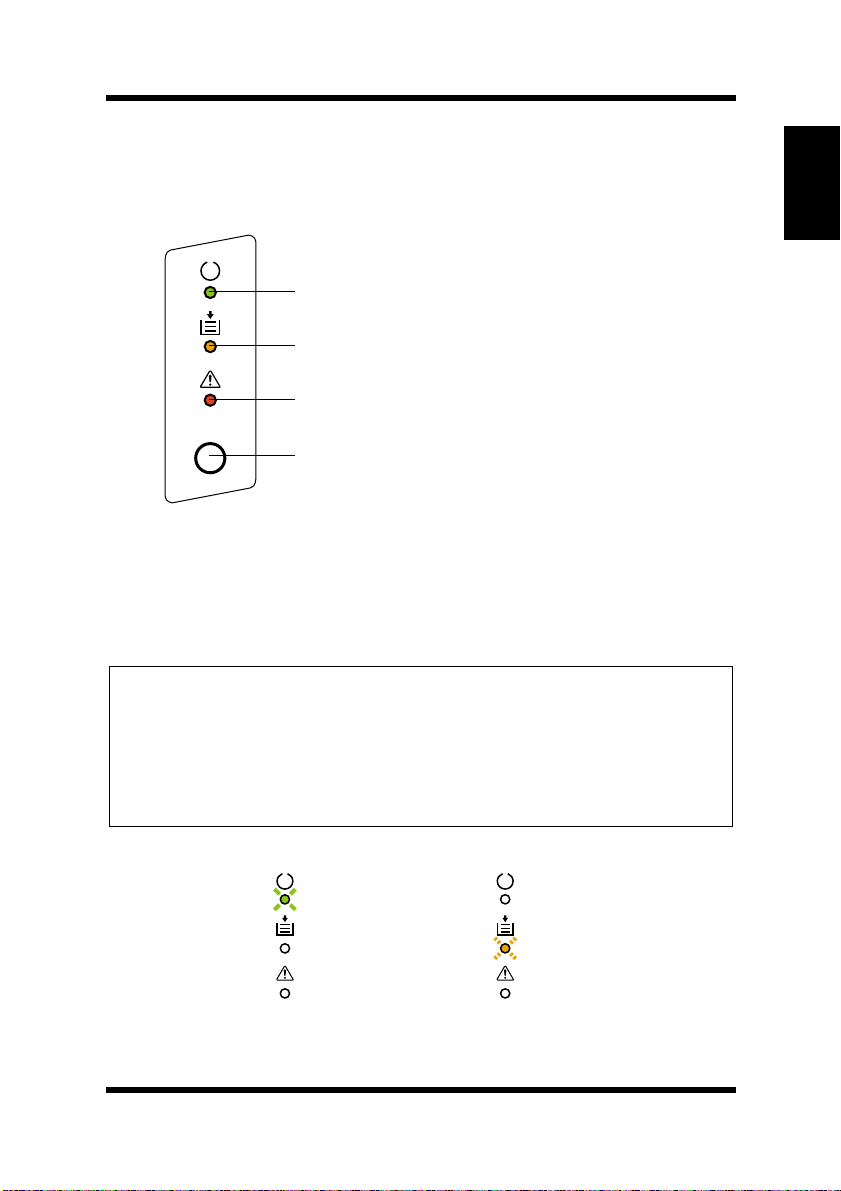
Control Panel
The control panel has three indicators and one button.
Ready (green) indicator
Paper (amber) indicator
Error (red) indicator
Panel button
Indicators
The three indicators turn on, off, or blink in c ombination to let you
know the current status of the printer.
Note
Chapter 1Introduction
◆ You can find out details of the printer’s status by checking the informa-
tion that appears on your computer screen (see “Starting Up the Status
Display” on pa ge 4-59).
◆ See “Indicator Lights (Printer Messages)” on page 6-30 for information
about how the control pa nel indicators indicate the current status of the
printer.
ex.)
Printer is rea dy.
Paper misfeed
1-5
Page 25

Control Panel
Panel Button
The panel button ca n be used to perform various operations a ccording
Chapter 1Introduction
to the status of the printer.
• Print configuration page
•Formfeed
For details, see “Using the Panel Button” on page 3-1.
1-6
Page 26

2Chapter
Setting-Up
Chapter 2Setting-Up
2
Page 27

Chapter 2Setting-Up
Page 28

Installation Precautions
Installation Precautions
Note the following important precautions when selecting a location for
the printer and when c onnecting it to a power source.
Selecting a Location for the Printer
A proper location helps to ensure that your printer provides you with
the long se rvice life for which it is designed. Double-check to make
sure that the location you select has the following c haracteristics.
• Choose a location that is well-ventilated.
• Make sure there is no chance of ammonia or other organic gasses
being generated in the area.
• The power outlet you plan to connect to for power should be nearby
and unobstructed.
• Make sure that the printer is not exposed to direct sunlight.
• Avoid areas in the direct airflow of air conditioners, heaters, or ventilators, and areas subjected to temperature and humidity extremes.
• Choose a sturdy, level surface where the printer will not be exposed
to strong vibration.
• Keep the printer away from any objects that m ight block its heat
vents.
• Do not locate the printer near curtains or other combustible objects.
• Choose an area where there is no possibility of the printer being
splashed with wa ter or other liquids.
• Make sure that the surrounding area is c lean, dry, and free of dust.
Chapter 2Setting-Up
2-1
Page 29
Chapter 2Setting-Up
Installation Precautions
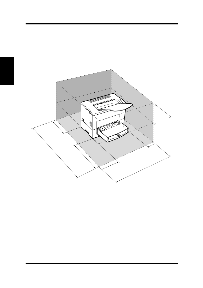
Space Requirements
Be sure to provide space around the printer as indicated below, to
ensure easier printer operation, paper and toner replacement, and maintenance.
11-3/4 in.
/30cm
6in./
15 cm
24-3/4 in.
/63cm
2-2
40-1/2 in./
103 cm
23-1/2 in./
60 cm
11-3/4in./30cm
4in./10cm
33 in. / 84 cm
Page 30

Installation Precautions
Power Source
The following are the power source requirements for this printer.
Power supply:
220-240 V at 50–60 Hz
Voltage fluctuation:
220-240 V, ± 10%
Frequency fluctuation:
Within ±3Hz
Note
◆ Use a power source with minimal voltage and frequency fluctuation.
◆ Only use an outlet that i s rated for the voltage capacity specified for this
printer.
◆ Be s ure to plug the power cord all the way into the outlet. The outlet
should be located near the printer and be easily accessible so you can
unplug the power cord immediately should any problem occur.
◆ Make sure the outlet you use is visible, and not hidden behind the printer
or any other object.
◆ If any other e lectrical equipment is plugged into the same outlet, make
sure that the capacity of the outlet is not exceeded.
◆ If you use an e xtension c ord, make sure its capacity is greater than the
power consumption of the printer. Using an extension cord with a lower
capacity creates the danger of fire.
◆ Never use a multiple socket to connect other appliances or machines to
the same outlet being used to power the printer.
Chapter 2Setting-Up
2-3
Page 31

Installation Precautions
Grounding
Always gr ound the printer to guard against the danger of e lectrical
shock. To ground the printer, connect the grounding wire to the ground
terminal of the electrical outlet you are plugging in to or to a grounding
contact that complies with local electrical standards in your area.
Note
Chapter 2Setting-Up
◆ Never connect the grounding wire to a gas pipe, the grounding wire for a
telephone, or to a water pipe.
2-4
Page 32

Operational Precautions
Operational Precautions
Note the following important precautions whe never using the printer.
Operating Environment
The following describes the operating environment required when
using the printer.
Temperature:
10° to 35°C(50°Fto95°F) with fluctuation of 10°C (18°F ) per hour
Humidity:
15% to 85% with fluctuation of 20% per hour
Printer
The following describes precautions for using the printer.
• Never turn the printer off or open any of its covers during a print
operation.
• Never place flammable gasses, liquids or objects that generate magnetic forces near the printer.
• When unplugging the power cord, always grasp the plug and never
pull on the cord. A damaged cord creates the danger of fire or electrical shock.
• Never touch the power cord when your hands are wet. Doing so creates the danger of electrical shock.
• Always unplug the power cord before m oving the printer. Failure to
do so can damage the power cord, creating the danger of fire or
electrical shock.
• Always unplug the power cord if you do not plan to use the printer
for a long time.
• Never try to remove any secured panel or cover. The interior of the
printer contains high-voltage circuitry which creates the danger of
electrical shock when exposed.
• Never try to modify the printer. Doing so creates the danger of fire
or electrical shock.
Chapter 2Setting-Up
2-5
Page 33

Chapter 2Setting-Up
Operational Precautions
• Never place any heavy objects on the power cord, pull on it or bend
it. Doing so creates the danger of fire or electrical shock.
• Always make sure the printer is not placed on the electrical cord or
the communications cables of any other electrical equipment. Also
make sure that cords and cables do not get into the printer’s mechanism. Any of these conditions create the danger of malfunction and
fire.
• Always take care so that paper clips, staples, or other small pieces
of metal do not get into the printer through its vents or other openings. S uch objects create the danger of fire or electrical shock.
• Do not allow water or other liquids to spill on or near the printer.
Fire or electrical shock can occur should water or liquid come into
contact w ith the printer.
• Should liquid or any piece of metal accidently get inside the printer,
immediately turn it off, unplug the power cord, a nd contact customer support. Failure to take this immediate action creates the danger of fire or electrical shock.
• Whenever the printer emits unusually high amounts of heat, smoke,
an unusual odor, or noise, immediately turn it off, unplug it, and
contact customer support. Failure to take this immediate action creates the danger of fire or electrical shock.
Caution
◆ Be sure to locate the printer in a well-ventilated location. A minimal
amount of ozone is generated during normal operation of this
printer. Because of this, an unpleasant odor may result when the
printer is used for extensive printing in a poorly ventilated area. For
comfortable, healthy, and safe operation, b e sure to locate the
printer in a well-ventilated area.
2-6
Page 34

Operational Precautions
Attention
◆ Placer l’imprimante dans une pièce l a rgement v entilée
Une quantité d ’ozone négligable est d égagée pendant le fonctionnement de l’impr ima nte quand celle-ci est utilisée normalement.
Cependant, une odeur désagréable pent être ressentie dans les pièces
dont l’aération est insuffisante et lorsqu’une utilisation prolongée de
l’imprimante est effectuée. Pour avoir la certitude de travailler dans
des cond itions de confort, santé et sécurité, il est préférable de bien
aérer la pièce où se trouve l’imprimante.
Printer Supplies
Note the following precautions when handling printer supplies such as
the imaging cartridge and paper.
• Avoid storing printer supplies in the following locations.
• Areas subjected to direct sunlight. Additionally, the imaging cartridge must be protected from fluorescent light.
• Areas exposed to open flame.
• Areas subjected to high humidity.
• Areas subjected to large amounts of dust.
• Keep paper that has been removed from its wrapper, but not yet
loaded onto the printer tray, in a sealed plastic bag and store it in a
cool, dark location.
• Use only the imaging cartridge that is expressly specified for this
printer.
• Keep supplies out of the reach of children.
• Should your hands become soiled with toner, immediately wash
them with soap and water.
Caution
Chapter 2Setting-Up
◆ Whenever you remove the imaging cartridge from the printer,
immediately wrap it with a cloth to protect it against overexposure to
light.
2-7
Page 35

Installing
Installing
Unpacking the Printer
1 Take the items and accessories shown below out of the carton.
Chapter 2Setting-Up
1
3
2
4
1. Face-down tray
2. Printer
3. Accessories
Installation Guide
CD-ROM
Power cord
4. Tray 1
Caution
◆ After unpacking, keep all packing materials out of the reach
of children.
Note
2-8
◆ Keep all the boxes and packing materials that the printer comes in
for later use when transporting the printer.
Page 36

Installing
2 Remove the plastic bag a nd peel off the shipping tape from the
printer.
3 Pull out the two cushions from the paper feed inlet.
4 Pull out the plastic-lead strip from the paper feed inlet.
Chapter 2Setting-Up
2-9
Page 37

Chapter 2Setting-Up
Installing
5 Remove the tape strip from the back of the printer.
For instructions on installing the optional item(s), see “Options” on
page 2-20.
Installing the Face-Down T ray
With both hands, gently bend the face-down tray inwards and insert
one of its tabs into its holder on the upper portion of the printer. Continue to bend the face-down tray so that it curves enough for the second tab to fit into its holder and release the tray into position.
2-10
Page 38

Installing
Installing Tray 1
1 Using the left and right slots in the printer as guides, gently push
Tray 1 until it cannot be inserted any further (as shown in the
illustration).
2 Attach the tray cover onto Tray 1.
Chapter 2Setting-Up
2-11
Page 39

Chapter 2Setting-Up
Setting-Up
Setting-Up
Set-up the printer according to the following instructions.
Connecting the Power Cord
1 Make sure thatthe power switch is in the ❍(Off) position.
2 Connect one e nd of the power cord that comes with the printer to
the power cord socket. Plug the other end into a power outlet.
2-12
Page 40

Loading Paper
1 Remove the tray cover from Tray 1.
2 Open all three paper guides.
Setting-Up
Chapter 2Setting-Up
2-13
Page 41

Chapter 2Setting-Up
Setting-Up
3 Place a stack of paper in the c enter of Tray 1. Secure the stack
by adjusting the paper guides.
4 Replace the tray cover onto Tray 1.
2-14
Page 42

Setting-Up
TurningOnthePrinter
■ After connecting the printer to a power outlet, press the power
switchtoturniton.
Turning on the printer causes all the indicators on the control panel
to light, which indicates that the printer is warming up. In about 23
seconds or less,only the Ready indicator remains lit, indicating that
the printer is ready to print.
Note
Chapter 2Setting-Up
◆ The printer automatically enters a power saving mode after a set
period of time in which it does not receive a print command from t he
computer. The default setting is 15 minutes, however, the time period
can be changed using the control panel (see “Using the Control
Panel” on page 4-63). Whenever the printer receives a print command while in the power saving mode, it will automatically start to
warm up before printing.
2-15
Page 43

Chapter 2Setting-Up
Setting-Up
Testing the Printer
Perform the following procedure to print a configuration page and see
if the printer is working correctly.
Note
◆ See “ No Output” on page 6-17 for information on what to do if the con-
figuration page does not print when you press the panel button .
1 Place the Le tter size paper onto Tray 1. 2 Make sure that both the Paper and Error indicators are off, and
the Ready indicator is on. This indicates there is no existing
error condition and no data remaining to be printed.
3 Briefly press the panel button to start the configuration page
print operation.
Face-down tray
Panel button
2-16
Tray 1
Page 44

Sample Configuration Page
Setting-Up
Chapter 2Setting-Up
2-17
Page 45

Setting-Up
Connecting to a Computer
For Parallel Interface
Caution
◆ Always use a shielded interfacecable.Useof an unshielded cable can
result in radio interference with data.
Chapter 2Setting-Up
Note
◆ You must purchase an IE EE 1284 type-B cable for connection between
the printer and a computer. For detailed specifications of the interface
cable,see “Interface Connector and Cable” on page 7-7.
◆ The user assumes all responsibility as to the quality and performance of
the cable.
1 Make sure that the printer and the computer you are connecting
it to are both turned off.
2 Connect one end of the interface cable to the parallel port of the
computer.
3 Connect the other end of the interface cable to the parallel inter-
face connector on the back of the printer. Secure the interface
cable using the two c lips on the parallel interface connector.
2-18
Page 46

Setting-Up
For USB Interface
Note
◆ This printer cannot be connected with a USB cable to a computer run-
ning Windows 95 or Windows NT 4.0.
1 Turn on your computer and start up Windows. 2 Turn on the printer. 3 Check that Windows has finished starting up and that the printer
is ready.
4 Connect one end of the interface cable to the USB port of the
computer.
5 Connect the other end of the interface cable to the USB interface
connector on the back of the printer.
Chapter 2Setting-Up
Note
◆ If Windowsdoes not detect the new device, leave the printer on, unplug
both ends of the USB interface cable, and then reconnect it.
2-19
Page 47

Chapter 2Setting-Up
Options
Options
This section describes the optional items that are available for this
printer.
Second/Third Paper Cassette Unit
The second/third paper cassette unit comes equipped with a cassette
that c an hold up to 500 she ets of Letter size paper called Tray 2/Tray
3.
The same unit can accommodate a va riety of other paper trays as well
(A4, JIS B5, Legal, Executive). The second and third paper cassette
unitare interchangeable and can increase paperholding capacity to
1,000 sheets when installed together. Contact your dealer to find out
how you can add these trays to increase the capabilities of your printer.
2-20
Page 48

Space Requirements
Options
30 cm/113/4 in.
Chapter 2Setting-Up
103 cm/
40-1/2 in.
15 cm/
6in.
60 cm/231/2 in.
30 cm/11-3/4 in.
* when equipped with the third paper cassette unit.
10 cm/4 in.
84 cm/33in.
75 cm/291/2 in.
*87 cm/
34-1/4 in.
2-21
Page 49

Chapter 2Setting-Up
Options
Installing the Second/Third Paper Cassette Unit
1 Turn off the printer and then disconnect the power cord and
interface cable from the printer.
2 Remove the paper cassette unit and the cassette from their
packaging, including the protective tape used to hold the various
components in place.
2-22
Page 50

Options
3 Place the printer on top of the base unit. Make sure to align the
coupling pins of the base unit with the holes located underneath
the printer.
Second paper cassette un it Third paper cassette unit
Note
Chapter 2Setting-Up
◆ The printer weighs approximately 18 kg (39.7 lbs.) with the
optionalsecond paper cassette unit installed. Two people are
recommended to lift it when necessary.
4 Load paper onto Tray 2/Tray 3. See “Loading Paper onto Tray
2/Tray 3 (Option)” on page 3-13 for details.
2-23
Page 51

Chapter 2Setting-Up
Options
5 Replace the cassette cover and insert Tray 2 or Tray 3 into the
paper cassette unit.
Tray 2
Tray 3
2-24
Page 52

Options
Note
◆ Be sure to use both hands whenever the casse tte is removed from
or inserted into the paper cassette unit.
6 Connect the power cord to the printer and then turn on the
printer.
See“ConnectingthePowerCord”onpage2-12.
See “Turning On the Printer” on page 2-15.
7 Generate a configuration page to verify that Tray 2 or Tray 3 is
listed under Printer Configuration item.
See “Testing the Printer” on page 2-16.
Chapter 2Setting-Up
PRINTER CONFIGURATION
Tray 2 = Installed
Tray 3 = Installed
Duplex Unit = Not Installed
2-25
Page 53

Chapter 2Setting-Up
Options
Duplex Unit
Your printer supports double-sided printing if the optional duplex unit
is installed. Double-sided documents can be generated for binding
along e ither the short or long edges of the paper through the printer
software. For more information, refer to “Duplex Printing” on page 3-
17.
•Taketheduplexunitout of the shipping box.
• Remove the plastic bag and all shipping materials.
• Turn the printer off and then disconnect the power cord and interface cable from the printer.
Space Requirements
2-26
30 cm/113/4 in.
118cm/461/2 in.
60 cm/231/2 in.
30 cm/11-3/4 in.
10 cm/4 in.
84 cm/33 in.
30 cm/
11-3/4 in.
63 cm/243/4 in.
Page 54

Options
Installing the Duplex Un it
1 Turn off the printer and then disconnect the power cord and
interface cable from the printer.
2 Remove the duplex unit from the packaging including the pro-
tective tape used to hold the various components in place.
3 With a screwdriver or similar instrument, remove the flat clip
that is a ttached to the back of the main unit of the printer.
Chapter 2Setting-Up
2-27
Page 55

Chapter 2Setting-Up
Options
4 Align the “L” shaped duplex unit to the back of the main unit of
the printer so that the bottom of the “L” is inside of the opening
at the bottom of the printer.
2-28
Note
◆ Make sure that the connectorof the unit is inserted into the printer
securely.
Page 56

Options
5 Withone hand holding the duplexunit in position, use a Phillips
screwdriver to tighten the screws that are permanently attached
to the back of the duplex unit.
Note
◆ Hold up the duplex uni t with your hand duringinstallation until it
is secured to the printer with the screws.
Chapter 2Setting-Up
6 Connect the power cord to the printer and then turn the printer
on.
See“ConnectingthePowerCord”onpage2-12.
See “Turning On the Printer” on page 2-15.
7 Generate a c onfiguration page to verify that duplexunitislisted
under the P rinter Configuration item.
See “Testing the Printer” on page 2-16.
PRINTER CONFIGURATION
Tray 2 = Not Installed
Tray 3 = Not Installed
Duplex Unit = Installed
2-29
Page 57

Chapter 2Setting-Up
Options
Expansion Memory
You can avoid many errors caused by data overload by installing sufficient memory into the printer.
This printer comes with 8 MB of memory. You can increase memory
capacity up to 104 M B by installing an optional 8, 16 or 32 MB expan-
sion memory (SIMM) into the printer.
SIMMsare available from most computer retailers.
Installing the Expansion Memory
Warning
◆ Electric sho ck hazard! Do not remove any cover of the pr in ter that is
not directly specified for removal in the User’s Manual.
1 Turn off the printer and then disconnect the power cord and
interface cable from the printer.
2 Remove the expansion memory (SIMM) from its packaging. 3 Close the face-down tray an d press the top cover release but-
ton to open the top cover.
2-30
Page 58

Options
4 Remove the two screws that hold the side cover of the pr inter in
place w ith a screwdriver.
5 Clips secure the e xterior side cover from the inside of the printer.
Gently m aneuver the exterior side cover until the clips release
(see illustration).
Chapter 2Setting-Up
6 With the exterior side cover removed, the internal side cover of
the printer is exposed. With the screwdriver, loosen and remove
the four sc rews that secure the internal side cover.
2-31
Page 59

Chapter 2Setting-Up
Options
7 Remove the internal side cover to expose the main circuit.
Caution
◆ Do not touch any part of the main circuit inside the printer.
8 Being careful not to touch the connection points along the e dge
of the expansion memory,insert the expansion memory into one
of the available sockets on the main circuit
2-32
SIMM sockets
Page 60

• Insert the expansion memory at an angle a s shown and gently swing it into the socket.
• Apply pressure until the expansion m emory locks into place.
9 Replace the internal side cover using the four screws.
Options
Chapter 2Setting-Up
2-33
Page 61

Chapter 2Setting-Up
Options
10 Replace the external side cover using the two screws provided to
secure it in place.
11 Print a Confi guration Page (see page 2-16) and check to confirm
that the “Total Memory” item correctly shows the increase in
memory capacity. If it does not, repeat the above steps making
sure that the e xpansion memory is installed correctly.
Note
◆ Torelease the expansionmemory from the socket, push out on the
taps on each side of the socket.
◆ Once the expansion memory has been installed, be sure to reset
the Printer Memory Setting to reflect the new memory capacity
(see “Using the Control Panel” on page 4-63).
2-34
Page 62

3Chapter
Using the Printer
Chapter 3Using the Printer
3
Page 63

Chapter 3Using the Printer
Page 64

Using the Panel Button
Using the Panel Button
The panel button can be used to perform various operations according
to the status of the printer.
Panel button
Print Configuration Page
Use the following procedure whenever you want to configuration for
printer.
■ Press the panel button while printer is idle without a ny errors and
job requests. See “Testing the Printer” on page 2-16 for details.
Chapter 3Using the Printer
Form Feed
Use the following procedure whenever a print job is canceled due to a
memoryoverflow.
■ Press the panel button to perform a form feed.
3-1
Page 65

Printing Paper
Printing Paper
Type
Caution
◆ This printer i s designed to print on onl y the following types of paper.
Paper Source Manual
Paper Type
Plain Paper
Chapter 3Using the Printer
60-90 g/m
60-90 g/m
Special
Paper
weight:
2
(16 - 24 lbs.)
Recycled Paper
weight:
2
(16 - 24 lbs.)
Transparency
Sheet
Labels ❍❍None
Letterhead ❍❍None
Envelopes ❍❍No ne
Thick Paper
weight: 90-163 g/
2
m
(24 to 43-1/4
lbs.
Feed
Tray
❍❍❍
❍❍❍
❍❍None
❍❍None
Tray 1
Tray 2/
Tray 3
Note
◆ Special paper is not supported for duplex printing.
3-2
Page 66

Printing Paper
Size
Caution
◆ This printer is designed to print on only the following sizes of paper.
Standard sizes
Paper Source Manual
Feed
Paper Size
A4
210 mm × 297 mm
A5
148 mm × 210 mm
JIS B5
Standard
Size
*1.Each of the 5 cassettes of Tray 2/Tray 3 support one of the 5 types of paper
that are c ompatible with this printer.
*2.Letteris standard cassette size for the second/third paper c assette unit.
182 mm × 257 mm
Legal
8-1/2 in.× 14 in.
Letter
8-1/2 in. × 11 in.
Executive
7-1/4 in. × 10-1/2 in.
Tray
❍❍❍
❍❍None
❍❍❍
❍❍❍
❍❍❍
❍❍❍
Tray 1
Tray 2/
Tray 3
*2
*1
Chapter 3Using the Printer
3-3
Page 67

Printing Paper
Envelope and Custom Size
Paper Source Manual
Feed
Paper Size
Env. DL
110 mm × 220 mm
Env. C5
162 mm × 229 mm
Env. B5
Chapter 3Using the Printer
Envelope
and Custom Size
176 mm × 250 mm
Env. Com10
4-1/8 in. × 9-1/2 in.
Env. Monarch
3-7/8 in. × 7-1/2 in.
Custom Size
3-1/2 in.to8-1/2 in.
× 6 in. to 14 in.
Tray
❍❍None
❍❍None
❍❍None
❍❍None
❍❍None
❍❍None
Tray 1
Tray 2/
Tray 3
3-4
Page 68

Printing Paper
Note
◆ Do not use the following types of paper to avoid reduced print quality,a
misfeed or print failure.
• Paper already used in a thermal transfer printeror ink jet printer.
• Paper that is too thin or too thick.
• Paper folded, curled or torn.
• Paper having binding holes or perforations.
• Paper with surfaces that a re too sm ooth or too rough or with varying
surfaces.
• Paper having special coatings on their surfaces such as carbon paper,
heat-sensitive paper and pressure-sensitive paper.
• Sheets of various sizes.
• Paper not cut on right angles.
• Paper bound by glue, staples or clips.
• Paper affixed with labels which are easy to peel.
• Post cards that are warped or bent.
◆ Envelopes should m eet the following re quirement:
• Sharp folds and edges.
• General mailing envelopes without seals on the glued portion.
• Having flags thefull widthof theenvelope(unacceptable if the flap is
glued).
• Wrinkle-free, no fasteners.
◆ Generally, envelopes perform well, but some types may w rinkle. We
strongly recommend testing and type of envelope before buying it in
large amounts.
◆ For more information, refer to “Loading Paper” on page 3-7.
Chapter 3Using the Printer
3-5
Page 69

Printing Paper
Printable Area
This printer is designed to print on paper with a 4 mm (0.16 in.) margin
on all sides.
4mm
(0.16 in.)
4mm
(0.16 in.)
Chapter 3Using the Printer
4mm
(0.16in.)
Printable
area
4mm
(0.16 in.)
3-6
Page 70

Loading Paper
Loading Paper
The following sources can be used to feed paper into the printer:
•Tray1
• Manual feed tray
• Tray 2/Tray 3 (option)
Tray 1 is the standard source for supplying paper to the printer. Various
types and sizes of paper can be fed from this tray.
You can also add Tray 2/Tray3 a s a secondary/third paper source. See
“Second/Third Paper Cassette Unit” on page 2-20 for details on using
this tray unit.
Whenever you are using special size paper, be sure to use the printer
driver installed on the computer to specify the printing area. You may
experience some variation in print quality when using special size
paper.
Always r emember that paper storage conditions greatly affect print
quality. Store paper in its original package. Keep paper out of areas
subject to extreme temperatures or humidity.
Chapter 3Using the Printer
3-7
Page 71

Loading Paper
Loading Paper onto Tray 1
You can load up to 250 sheets of standard paper onto Tray 1. See
“Printing Paper” on page 3-2 for details on paper sizes and types.
1 Remove the tray cover from Tray 1.
Chapter 3Using the Printer
2 Open the paper guides.
3-8
Page 72

Loading Paper
3 Place a stack of paper in the c enter of Tray 1. Adjust the paper
guides so that both the left and the right sides of the paper stack
are secure.
Maximumlevel
mark
Note
◆ A maximum level markon the paperguide shows how high
youcanstackpaperonTray 1. Make sure that paper is stacked no
higher than this mark.
◆ Do not load additional paper until the paper currently loaded onto
Tray 1 is completely used.
Chapter 3Using the Printer
4 Replace the tray cover onto Tray 1.
3-9
Page 73

Loading Paper
Manual Loading (Manual Feed T ray)
1 Make sure thatthe tray cover is properly attached to Tray 1. 2 Open the paper guides.
Chapter 3Using the Printer
3 Insert the sheet of paper into the manual feed tray with the side
to be printed fa cing up.
3-10
Note
◆ Insert only one sheet of paper at a time when feeding manually.
Page 74

Loading Paper
4 Adjust the paper guides so that both sides of the paper are
secure.
Printing on Envelopes
The manual feed tray supports Commercial 10, Monarch, DL, C5,
and B5 envelopes.
Note
◆ Because there is great variation in the quality of paper used for enve-
lopes, we suggest that you produce test prints of various types before
purchasing any envelope in large quantities for use with this printer.
◆ Make sure that all edges are creased sharply a nd that all flaps are folded
correctly.
◆ Do not use envelopes that a re self-adhesive. Use only envelopes that
have standard sealing that sticks after it is moistened.
◆ Use envelopes of which flaps run the entire length of the envelope. Enve-
lopes that seal at one end will not feed properly.
◆ Do not use envelopes that have a window. Such envelopes can seriously
damage the printer.
◆ Do not use envelopes that are wrinkled.
◆ Never use envelopes that have clasps or any other type of fastener that
can damage the printer.
◆ Do not store envelopes in an area that is subject to high humidity.
Chapter 3Using the Printer
3-11
Page 75

Loading Paper
1 Place the e nvelope with the side to be printed facing up on the
tray. The flap of the envelope should be facing down and to the
left.
Note
◆ Insert only one envelope at a time when feeding manually.
2 Make sure that the envelope is placed in the center of the tray
andthatitissecuredbythepaper guides.
Chapter 3Using the Printer
3-12
Page 76

Loading Paper
Loading Paper onto Tray 2/Tray 3 (Option)
You can load up to 500 sheets of standard paper onto Tray 2/Tray 3.
See “Printing Paper” on page 3-2 for details on paper sizes and types.
Note
◆ Make sure that the Tray2/Tray 3 for the proper size of paper to be used
for printinghasbeeninstalled into the second/third pa p er casse tte unit.
See “Second/ThirdPaper CassetteUnit” on page 2-20 for i nstructions on
inserting (and removing) the Tray 2/Tray 3 into (and from) the second/
third paper cassette unit.
◆ To remove Tray 2/Tray 3 from the unit, pull it out as far a s it will go
without force. Then gently raise the forward-end up, and remove Tray 2/
Tray 3 from the unit.
1 Slide Tray 2/Tray 3 out of the second/third papercassette
unit.
Tray 2 Tray 3
Chapter 3Using the Printer
3-13
Page 77

Loading Paper
2 Remove the cassette cover from Tray 2/Tray 3.
Chapter 3Using the Printer
3 Press down on the paper lifting plate located inside of Tray 2/
Tray 3 until it locks.
3-14
Page 78

Loading Paper
4 Place a stackof up to 500 sheets of paper into Tray 2/Tray 3 so
that the side that was facing up when the paper was unwrapped
is still facing up.
Note
◆ A maximum levelmarkinside the inlet of Tray 2/Tray 3 shows
how high you can stack paper on Tray 2/Tray 3.Makesurethat
paper is stacked no higher than this mark.
Maximumlevel mark
Chapter 3Using the Printer
◆ Tray2/Tray 3 does not support landscape oriented paper feeding.
◆ Do not load additional paper until a ll the paper currently on Tray
2/Tray 3 is completely used up.
3-15
Page 79

Loading Paper
5 Replace the cassette cover and insert Tray 2/Tray 3 into the
second/third paper cassette unit.
Tray 2
Chapter 3Using the Printer
Tray 3
3-16
Page 80

Duplex Printing
Duplex Printing
This feature prints document data on both sides of a sheet of paper.
Installation of the optional duplex unit is required to perform duplex
printing.
You can choose either Bind Long Edge or Bind Short Edge whe n generating duplex documents.
Bind Long Edge
AA
Portrait Landscape
Bind Short Edge
Portrait
A
A
A
A
AA
Landscape
Chapter 3Using the Printer
3-17
Page 81

Duplex Printing
The supported paper types and sizes for duplex printing a re as follows.
Paper Type
Plain p aper:
60-90 g/m2(16 - 24 lbs.)
Recycle paper:
60-90 g/m2(16 - 24 lbs.)
Note
◆ Do not use special paper (transparencies, labels, envelopes, letterhead
and thick paper) for duplex printing.
Chapter 3Using the Printer
Paper Size
A4, A5, JIS B5, Letter,Legal, Executive.
Note
◆ The Long Edge Binding setting of the printer driver cannot be used to
print duplex documents on custom size paper.
Remember the following points when generating duplex documents:
• The size of both original documents that will be used to make one
duplex document must be the same.
• The original document that is loaded f irst into the duplex unit will
be output f ace down.
3-18
Page 82

4Chapter
PCL Printer Driver
Chapter 4PCL Printer Driver
4
Page 83

Chapter 4PCL Printer Driver
Page 84

Introduction
Introduction
The Laser Printer 300 Series PCL Printer Driver was specially developed to provide true Windows-based printing for users. The Laser
Printer 300 Series PCL P rinter Driver consists of three programs: the
Laser Printer 300 Series PCL Printer Driver, the Printer Status Display
and the Control Panel.
PCL Printer Driver:
This program is built into the operating system. It controls printer
operations and enables proper printing.
For detailed instructions on installing the PCL Printer Driver, refer
to page 4-17, 4-21, 4-27 or 4-30.
Status Display:
This program displays information about the current status of the
computer’s local printer.
For detailed instructions on installing the Status Display, refer to
page 4-36.
Control Panel:
This program displays the current settings of the computer’s local
printer. You can also use Control Panel to change settings and to
reset counters.
For detailed instructions on installing the Control Panel, re fer to
page 4-36.
Important!
Chapter 4PCL Printer Driver
◆ The printer driver for your Laser Printer 300 Series is located on the CD-
ROM that comes with your printer.
4-1
Page 85

Chapter 4PCL Printer Driver
System Requirements
System Req uiremen ts
The following describes the minimum system requirements that are
necessary to correctly run the Laser Printer 300 Series PCL Printer
Driver.
OperatingSystem: MicrosoftWindows95,Windows98, WindowsMe,
Windows NT 4.0 or Windows 2000
Personal Computer: IBM-compatible PC with at least a 486DX
16MHz CPU (Pentium processor recommended)
CD-ROM drive
I/O Interface: IEEE 1284 type-B parallel
USB (not available with Windows 95 or Windows NT 4.0)
Memory:Atleast8MBofPCRAM
Free Disk Space: Approximately 5MB for files
Important!
◆ When connecting the printer to the computer with a USB cable, be sure
to read the section “Installing the USB Device Driver for the Laser
Printer300Series”onpage4-3.
If the printer is not being connected to the computer with a USB cable,
skip the following section, and then continue to the appropriate printer
driver installation section for your computer’s operating system.
4-2
Page 86

Installing the USB Device Driver for the Laser Printer
300 Series
Installing t he USB Device Driver for the Laser Printer 300 Series
When connecting the Laser Printer 300 Series printer to your c omputer
with a USB cable, install the USB device driver according to the following instructions before installing the printer driver.
This printer cannot be connected with a USB cable to a computer running Windows 95 or Windows NT 4.0.
To Install the USB Device Driver Under Windows 98
1 Turn on your computer and start up Windows 98. 2 Turn on the printer. 3 Check that Windows 98 has finished starting up and that the
printer is ready.
4 Insert the Printer Driver CD-ROM that comes with your printer
into your c omputer ’s CD-ROM drive.
4-3
Chapter 4PCL Printer Driver
Page 87

Chapter 4PCL Printer Driver
Installing the USB Device Driver for the Laser Printer
300 Series
5 Connect the printer to the computer with the USB cable (For
more details, refer to “Connecting to a Computer” on page 2-
18.) to display the
Add New Hardware Wizard dialog.
6 Click Next to display the next dialog. 7 Check the Search for the best driver for your device. (Rec-
ommended).
option button, and then click Next.
8 When the next dialog appears, check the Specify a location
box, and then click Bro wse.
9 Browse the CD-ROM a nd navigate to: English\usb. Then, click
OK.
10 Follow the instructions that appear on your computer sc reen to
complete the installation.
4-4
Page 88

Installing the USB Device Driver for the Laser Printer
300 Series
11 When the following dialog appears, click Finish to finish the
installation.
This completes the installation of the USB device driver for the
Laser P rinter 300 Series printer.
12 When the Add Printer Wizard dialog appears, continue with the
procedure in “To Install the PCL Printer Driver Using the Add
Printer Wizard” on page 4-25
.
4-5
Chapter 4PCL Printer Driver
Page 89

Chapter 4PCL Printer Driver
Installing the USB Device Driver for the Laser Printer
300 Series
To Install the USB Device Driver Under Windows Me
1 Turn on your computer and start up Windows Me. 2 Turn on the printer. 3 Check that Windows Me has finished starting up and that the
printer is ready.
4 Insert the Printer Driver CD-ROM that comes with your printer
into your c omputer ’s CD-ROM drive.
5 Connect the printer to the computer with the USB cable (For
more details, refer to “Connecting to a Computer” on page 2-
18.) to display the
Add New Hardware Wizard dialog.
6 Check the Specify the location of the driver (Advanced)
option button, and then click Next.
4-6
Page 90

Installing the USB Device Driver for the Laser Printer
300 Series
7 Check the Search for the best driver for your device. (Rec-
ommended)
and then click
option button, check the Specify a location box,
Browse.
8 Browse the CD-ROM a nd navigate to: English\usb. Then, click
OK.
Chapter 4PCL Printer Driver
9 Follow the instructions that appear on your computer sc reen to
complete the installation.
4-7
Page 91

Installing the USB Device Driver for the Laser Printer
300 Series
10 When the following dialog appears, click Finish to finish the
installation.
Chapter 4PCL Printer Driver
This completes the installation of the USB device driver for the
Laser P rinter 300 Series.
11 When the Add Printer Wizard dialog appears, continue with the
procedure in “To Install the PCL Printer Driver Using the Add
Printer Wizard” on page 4-25.
4-8
Page 92

Installing the USB Device Driver for the Laser Printer
300 Series
To Install the USB Device Driver Under Windows 2000
If the printer is connected to the computer using a USB cable, USB
Printing Support may automatically be incorporated, depending on the
operating system. In order to activate all functions of the Laser Printer
300 Series, the USB device driver must be installed.
Install the USB device driver for the Laser Printer 300 Series according
to the following procedure.
1 Turn on your computer and start up Windows 2000. 2 Turn on the printer. 3 Check that Windows 2000 has finished starting up and that the
printer is ready.
4 Insert the Printer Driver CD-ROM that comes with your printer
into your c omputer ’s CD-ROM drive.
Chapter 4PCL Printer Driver
4-9
Page 93

Chapter 4PCL Printer Driver
Installing the USB Device Driver for the Laser Printer
300 Series
5 Connect the printer to the computer with the USB cable (For
more details, refer to “Connecting to a Computer” on page 2-
18.) to display the Found New Hardware Wizard dialog.
6 Using the Found New Hardware Wizard, install the Laser Printer
300 Series PCL Printer Driver. See “To Install the PCL Printer
Driver Using Plug-and-Play” on page 4-30.
After installing the printer driver,install the US B device driver
for the Laser Printer 300 Series as described below.
7 Right-click the My Computer icon on the desktop, and then
click
Properties in the shortcut menu that appears. The System
Properties dialog appears.
8 Click the Hardware tab of the System Properties dialog, and
then click the
Device Manager button.
9 Double-click USB Printing Support below Universal Serial
Bus controllers
appears.
4-10
. The USB Printing Support Properties dialog
Page 94

Installing the USB Device Driver for the Laser Printer
300 Series
10 Click the Driver tab of the USB Printing Support Properties dia-
log, and then c lick
Update D river.
Chapter 4PCL Printer Driver
4-11
Page 95

Chapter 4PCL Printer Driver
Installing the USB Device Driver for the Laser Printer
300 Series
11 Click Next to display the next dialog.
12 Check the Search a suitable driver for my device (recom-
mended)
option button, and then click Next.
13 When the next dialog appears, check the Specify a loca tion
box, and then click Next.
14 Click Browse. 15 Browse the CD-ROM and navigate to: English\usb. Then, click
Open.
16 Click OK, and then click Next. 17 Follow the instructions that appear on your computer sc reen to
complete the installation.
4-12
Page 96

Installing the USB Device Driver for the Laser Printer
18 When the following dialog appears, click Cancel.
Note
◆ Be sure to click Cancel to stop the Add Printer Wizard.
300 Series
Chapter 4PCL Printer Driver
4-13
Page 97

Chapter 4PCL Printer Driver
Installing the USB Device Driver for the Laser Printer
300 Series
19 When the following dialog appears, click Finish to finish install-
ing the USB device driver.
Continue with this procedure to set the printer port.
20 ClickStart, point to Settings, and then click Printersto display
the Printers dialog.
21 In the Printers dialog, click the Laser Printer 300 Series PCL6
printer icon.
4-14
Page 98

Installing the USB Device Driver for the Laser Printer
22 Select Properties from the File menu.
300 Series
23 In the Properties dialog, click the Portstab, and then select
USB/001 Laser Printer 300 Series from the ports list.
Chapter 4PCL Printer Driver
4-15
Page 99

Chapter 4PCL Printer Driver
Installing the USB Device Driver for the Laser Printer
300 Series
Note
◆ Remove the check for the port with “Virtualprinter port for USB”
listed under
Printer 300 Series” listed under
Description, and then select the port with “Laser
Description.
24 Click Apply. 25 In the Printers dialog, click the Laser Printer 300 Series PCL6
printer icon, and then click Use Printer Offline in the File menu
to remove the check.
26 Click the General tab of the Properties dialog, and then click
Print Test Page.
Check that the test page is correctly printed by the printer.
This completes the installation and setting of the USB device
driver.
4-16
Page 100

Installing the PCL Printer Dr iver Under Windows 95
Installing t he PCL Printer Driver Under
Windows 95
This section provides information on installing the Laser Printer 300
Series PCL Printer Driver under Windows 95.
To Install the PCL Printer Driver Using Plugand-Play
1 After c onnecting the printer to your computer with the parallel
cable, turn on the printer.
2 Turn on your computer and start up Windows 95.
Update Device Driver Wizard dialog appears on the dis-
The
play.
Chapter 4PCL Printer Driver
3 Insert the Printer Driver CD-ROM that comes with your printer
into your c omputer ’s CD-ROM drive, and then click
Next.
4 Click the O ther Location button, type
D:\English\PCL6Driver\W95 and click OK. (In this example,
we assume that
D: is the name of the CD-ROM drive.)
4-17
 Loading...