

Page 1
Owner’s Handbook
Tiger XR
X and Tiger XCX
1
This handbook contains information on the Triumph Tiger XRX and Tiger XCX
motorcycles. Always store this Owner's Handbook with the motorcycle and refer to it
for information whenever necessary.
The information contained in this publication is based on the latest information
available at the time of printing. Triumph reserves the right to make changes at any
time without prior notice, or obligation.
Not to be reproduced wholly or in part without the written permission of
Triumph Motorcy c l e s L i m i t e d .
© Copyright 09.2014 Triumph Motorcycles Limited, Hinckley, Leicestershire, England.
Publication part number 3855459-EN issue 1.
Page 2

2
Table of Contents
This handbook contains a number of different sections. The table of contents below
will help you find the beginning of each section where, in the case of the major
sections, a further table of contents will help you find the specific subject required.
Foreword . . . . . . . . . . . . . . . . . . . . . . . . . . . . . . . . . . . . . . . . . . . . . . . . . . . . . . . . . . . . . . . . . 3
Foreword – Safety First. . . . . . . . . . . . . . . . . . . . . . . . . . . . . . . . . . . . . . . . . . . . . . . . . . . . . 6
Warning Labels . . . . . . . . . . . . . . . . . . . . . . . . . . . . . . . . . . . . . . . . . . . . . . . . . . . . . . . . . . .12
Parts Identification . . . . . . . . . . . . . . . . . . . . . . . . . . . . . . . . . . . . . . . . . . . . . . . . . . . . . . . 14
Serial Numbers . . . . . . . . . . . . . . . . . . . . . . . . . . . . . . . . . . . . . . . . . . . . . . . . . . . . . . . . . . . 19
General Information . . . . . . . . . . . . . . . . . . . . . . . . . . . . . . . . . . . . . . . . . . . . . . . . . . . . . . .21
How to Ride the Motorcycle . . . . . . . . . . . . . . . . . . . . . . . . . . . . . . . . . . . . . . . . . . . . . . . 91
Accessories, Loading and Passengers . . . . . . . . . . . . . . . . . . . . . . . . . . . . . . . . . . . . . . 103
Maintenance and Adjustment . . . . . . . . . . . . . . . . . . . . . . . . . . . . . . . . . . . . . . . . . . . . . 107
Storage. . . . . . . . . . . . . . . . . . . . . . . . . . . . . . . . . . . . . . . . . . . . . . . . . . . . . . . . . . . . . . . . . .157
Specifications . . . . . . . . . . . . . . . . . . . . . . . . . . . . . . . . . . . . . . . . . . . . . . . . . . . . . . . . . . . 159
Page 3
Foreword
3
FOREWORD
Owner's Handbook
Thank you for choosing a Triumph
motorcycle. This motorcycle is the
product of Triumph's use of proven
engineering, exhaustive testing, and
continuous striving for superior
reliability, safety and performance.
Please read this Owner's Handbook
before riding in order to become
thoroughly familiar with the correct
operation of your motorcycle's controls,
its features, capabilities and limitations.
This handbook includes safe riding tips,
but does not contain all the techniques
and skills necessary to ride a motorcycle
safely.
Triumph strongly recommends that all
riders undertake the necessary training
to ensure safe operation of this
motorcycle.
An electronic version of this Owner's
Handbook is available to download on
the internet at www.triumph.co.uk.
This handbook is also available from your
local dealer in:
•Brazilian
•Dutch
•French
•German
• Italian
• Japanese
•Spanish
•Swedish.
Talk t o Triu m p h
Our relationship with you does not end
with the purchase of your Triumph. Your
feedback on the buying and ownership
experience is very important in helping
us develop our products and services for
you. Please help us by ensuring your
dealership has your email address and
registers this with us. You will then
receive an online customer satisfaction
survey invitation to your email address
where you can give us this feedback.
Your Triumph Team.
Warning
This Owner's Handbook, and all other
instructions that are supplied with
your motorcycle, should be considered
a permanent part of your motorcycle
and should remain with it even if your
motorcycle is subsequently sold.
All riders must read this Owner's
Handbook and all other instructions
which are supplied with your
motorcycle, before riding, in order to
become thoroughly familiar with the
correct operation of your motorcycle's
controls, its features, capabilities and
limitations. Do not lend your
motorcycle to others as riding when
not familiar with your motorcycle's
controls, features, capabilities and
limitations can lead to an accident.
Page 4
Foreword
4
Warnings, Cautions and
Notes
Throughout this Owner's Handbook
particularly important information is
presented in the following form:
Note:
•This note symbol indicates points of
particular interest for more efficient
and convenient operation.
Warning Labels
At certain areas of the
motorcycle, the symbol
(left) can be seen. The
symbol means 'CAUTION:
REFER TO THE HANDBOOK'
and will be followed by a
pictorial representation of
the subject concerned.
Never attempt to ride the motorcycle or
make any adjustments without
reference to the relevant instructions
contained in this handbook.
See page 12 for the location of all labels
bearing this symbol. Where necessary,
this symbol will also appear on the pages
containing the relevant information.
Maintenance
To ensure a long, safe and trouble-free
life for your motorcycle, maintenance
should only be carried out by an
authorised Triumph dealer. Only an
authorised Triumph dealer will have the
necessary knowledge, equipment and
skills to maintain your Triumph
motorcycle correctly.
To locate your nearest Triumph dealer,
visit the Triumph web site at
www.triumph.co.uk or telephone the
authorised distributor in your country.
Their address is given in the service
record book that accompanies this
handbook.
Warning
This warning symbol identifies special
instructions or procedures, which if
not correctly followed could result in
personal injury, or loss of life.
Caution
This caution symbol identifies special
instructions or procedures, which, if
not strictly observed, could result in
damage to, or destruction of,
equipment.
Page 5

Foreword
5
Off-road Use
The Tiger XRX and Tiger XCX are
designed for on-road and light off-road
use. Light off-road use includes use on
unpaved, dirt or gravel roads, but does
not include riding on any motocross
course, any off-road competition (such
as motocross or enduro riding), or riding
off-road with a passenger.
Light off-road use does not include
jumping the motorcycle or riding over
obstacles. Do not attempt to jump over
any bumps or obstacles. Do not attempt
to ride over any obstacles.
Noise Control System
Tampering with the Noise Control
System is prohibited.
Owners are warned that the law may
prohibit:
• The removal or rendering
inoperative by any person other
than for purposes of maintenance,
repair or replacement, of any device
or element of design incorporated
into any new vehicle for the purpose
of noise control prior to its sale or
delivery to the ultimate purchaser or
while it is in use and,
• the use of the vehicle after such
device or element of design has been
removed or rendered inoperative by
any person.
Immobiliser and Tyre
Pressure Monitoring System
This device complies with part 15 of the
FCC Rules.
Operation is subject to the following two
conditions:
• This device may not cause harmful
interference
• This device must accept any
interference received, including
interference that may cause
undesired operation.
Changes or modifications to the device
could void the user's authority to
operate the equipment.
Tyre s
With reference to the Pneumatic Tyres
and Tubes for Automotive Vehicles
(Quality Control) Order, 2009, Cl. No. 3 (c),
it is declared by M/s. Triumph
Motorcycles Ltd. that the tyres fitted on
this motorcycle meet the requirements
of IS 15627: 2005 and comply with the
requirements under Central Motor
Vehicle Rules (CMVR), 1989.
Page 6
Foreword – Safety First
6
FOREWORD – SAFETY FIRST
The Motorcycle
Warning
The Tiger XRX and Tiger XCX are
designed for on-road and light offroad use. Light off-road use includes
use on unpaved, dirt or gravel roads,
but does not include riding on any
motocross course, any off-road
competition (such as motocross or
enduro riding), or riding off-road with
a passenger.
Light off-road use does not include
jumping the motorcycle or riding over
obstacles. Do not attempt to jump
over any bumps or obstacles. Do not
attempt to ride over any obstacles.
Extreme off-road use could lead to
loss of motorcycle control and an
accident.
Warning
This motorcycle is not designed to tow
a trailer or be fitted with a sidecar.
Fitting a sidecar and/or a trailer may
result in loss of control and an
accident.
Warning
This motorcycle is designed for use as
a two-wheeled vehicle capable of
carrying a rider on his/her own, or a
rider and one passenger.
The total weight of the rider, and any
passenger, accessories and luggage
must not exceed the maximum load
limit of:
Tiger XR
X – 219 kg (483 lb)
Tiger XC
X – 217 kg (478 lb).
Warning
This motorcycle is fitted with a
catalytic converter below the engine,
which along with the exhaust system
reaches very high temperature during
engine operation. Flammable materials
such as grass, hay/straw, leaves,
clothing and luggage etc. could ignite
if allowed to come into contact with
any part of the exhaust system and
catalytic converter; always ensure
flammable materials are not allowed to
contact the exhaust system or
catalytic converter.
Page 7
Foreword – Safety First
7
Fuel and Exhaust Fumes Helmet and Clothing
Warning
PETROL IS HIGHLY FLAMMABLE:
Always turn off the engine when
refuelling.
Do not refuel or open the fuel filler cap
while smoking or in the vicinity of any
open (naked) flame.
Take care not to spill any petrol on the
engine, exhaust pipes or silencers
when refuelling.
If petrol is swallowed, inhaled or
allowed to get into the eyes, seek
immediate medical attention.
Spillage on the skin should be
immediately washed off with soap and
water and clothing contaminated with
petrol should immediately be removed.
Burns and other serious skin
conditions may result from contact
with petrol.
Warning
Never start your engine or let it run
for any length of time in a closed area.
The exhaust fumes are poisonous and
may cause loss of consciousness and
death within a short time. Always
operate your motorcycle in the openair or in an area with adequate
ventilation.
Warning
When riding the motorcycle, both rider
and passenger must always wear a
motorcycle helmet, boots, eye
protection, gloves, trousers (close
fitting around the knee and ankle) and
a brightly coloured jacket. Brightly
coloured clothing will considerably
increase a rider's (or passenger's)
visibility to other operators of road
vehicles. Although full protection is
not possible, wearing correct
protective clothing can reduce the risk
of injury when riding.
Warning
A helmet is one of the most important
pieces of riding gear as it offers
protection against head injuries. You
and your passenger's helmet should
be carefully chosen and should fit you
or your passenger's head comfortably
and securely. A brightly coloured
helmet will increase a rider's (or
passenger's) visibility to other
operators of road vehicles.
An open face helmet offers some
protection in an accident though a full
face helmet will offer more.
Always wear a visor or approved
goggles to help vision and to protect
your eyes.
cbma
Page 8
Foreword – Safety First
8
Riding
Warning
Never ride the motorcycle when
fatigued or under the influence of
alcohol or other drugs.
Riding when under the influence of
alcohol or other drugs is illegal.
Riding when fatigued or under the
influence of alcohol or other drugs
reduces the rider's ability to maintain
control of motorcycle and may lead to
loss of control and an accident.
Warning
All riders must be licenced to operate
the motorcycle. Operation of the
motorcycle without a licence is illegal
and could lead to prosecution.
Operation of the motorcycle without
formal training in the correct riding
techniques that are necessary to
become licenced is dangerous and
may lead to loss of motorcycle control
and an accident.
Warning
Always ride defensively and wear the
protective equipment mentioned
elsewhere in this foreword. Remember,
in an accident, a motorcycle does not
give the same impact protection as a
car.
Warning
This Triumph motorcycle should be
operated within the legal speed limits
for the particular road travelled.
Operating a motorcycle at high speeds
can be potentially dangerous since the
time available to react to given traffic
situations is greatly reduced as road
speed increases. Always reduce speed
in potentially hazardous driving
conditions such as bad weather or
heavy traffic.
Warning
Continually observe and react to
changes in road surface, traffic and
wind conditions. All two-wheeled
vehicles are subject to external forces
which may cause an accident. These
forces include but are not limited to:
• Wind draft from passing vehicles
• Potholes, uneven or damaged road
surfaces
•Bad weather
• Rider error.
Always operate the motorcycle at
moderate speed and away from heavy
traffic until you have become
thoroughly familiar with its handling
and operating characteristics. Never
exceed the legal speed limit.
Page 9
Foreword – Safety First
9
Handlebars and Footrests
Warning
The rider must maintain control of the
vehicle by keeping hands on the
handlebars at all times.
The handling and stability of a
motorcycle will be adversely affected if
the rider removes his hands from the
handlebars, resulting in loss of
motorcycle control and an accident.
Warning
The rider and passenger must always
use the footrests provided, during
operation of the vehicle.
By using the footrests, both rider and
passenger will reduce the risk of
inadvertent contact with any
motorcycle components and will also
reduce the risk of injury from
entrapment of clothing.
Warning
The bank angle indicators must not be
used as a guide to how far the
motorcycle may be safely banked. This
depends on many various conditions
including, but not limited to, road
surface, tyre condition and weather.
Banking to an unsafe angle may cause
instability, loss of motorcycle control
and an accident.
Warning
Use of a motorcycle with the bank
angle indicators worn beyond the
maximum limit will allow the
motorcycle to be banked to an unsafe
angle.
The bank angle indicators have
reached the maximum wear limit and
should be replaced when they have
worn down to a length of 20 mm.
Banking to an unsafe angle may cause
instability, loss of motorcycle control
and an accident.
Page 10
Foreword – Safety First
10
Parking
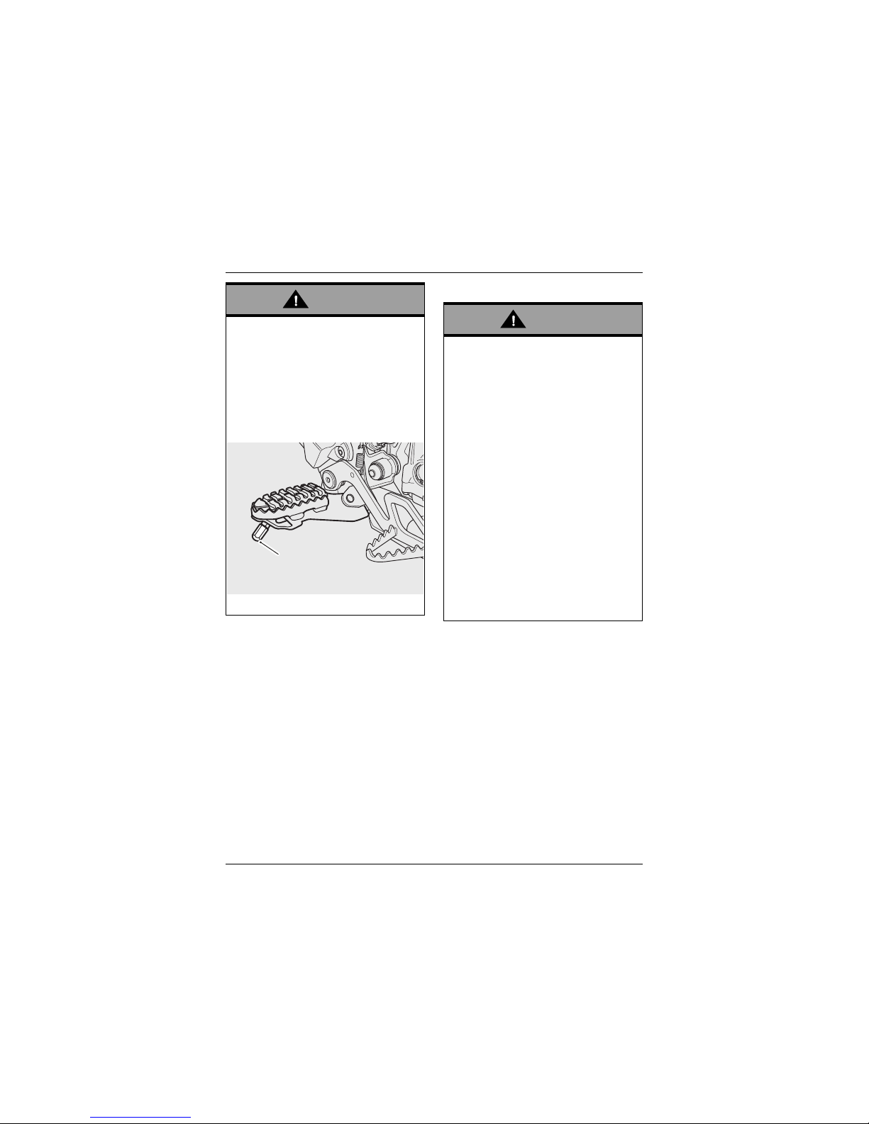
Warning
When banking and the bank angle
indicator, attached to the rider's
footrest, makes contact with the
ground, the motorcycle is nearing its
bank angle limit. A further increase of
the banking angle is unsafe.
Banking to an unsafe angle may cause
instability, loss of motorcycle control
and an accident.
1. Bank angle indicator
1
Warning
Always turn off the engine and
remove the ignition key before leaving
the motorcycle unattended. By
removing the key, the risk of use of
the motorcycle by unauthorised or
untrained persons is reduced.
When parking the motorcycle, always
remember the following:
Engage first gear to help prevent the
motorcycle from rolling off the stand.
The engine and exhaust system will be
hot after riding. DO NOT park where
pedestrians, animals and/or children
are likely to touch the motorcycle.
Do not park on soft ground or on a
steeply inclined surface. Parking
under these conditions may cause the
motorcycle to fall over.
For further details, please refer to the
How to Ride the Motorcycle section of
this Owner's Handbook.
Page 11
Foreword – Safety First
11
Parts and Accessories
Triumph does not accept any liability
whatsoever for defects caused by the
fitting of non-approved parts,
accessories or conversions or the fitting
of any approved parts, accessories or
conversions by non-approved personnel.
Maintenance/Equipment
Warning
Owners should be aware that the only
approved parts, accessories and
conversions for any Triumph
motorcycle are those which carry
official Triumph approval and are fitted
to the motorcycle by an authorised
dealer.
In particular, it is extremely hazardous
to fit or replace parts or accessories
whose fitting requires the dismantling
of, or addition to, either the electrical
or fuel systems and any such
modification could cause a safety
hazard.
The fitting of non-approved parts,
accessories or conversions may
adversely affect the handling, stability
or other aspects of the motorcycle
operation which may result in loss of
motorcycle control and an accident.
Warning
Consult your authorised Triumph
dealer whenever there is doubt as to
the correct or safe operation of this
Triumph motorcycle.
Remember that continued operation
of an incorrectly performing
motorcycle may aggravate a fault and
may also compromise safety.
Warning
Ensure all equipment that is required
by law is installed and functioning
correctly. The removal or alteration of
the motorcycle's lights, silencers,
emission or noise control systems can
violate the law. Incorrect or improper
modification may adversely affect the
handling, stability or other aspect of
the motorcycle operation, which may
result in loss of motorcycle control
and an accident.
Warning
If the motorcycle is involved in an
accident, collision or fall, it must be
taken to an authorised Triumph dealer
for inspection and repair. Any accident
can cause damage to the motorcycle
that, if not correctly repaired, may
cause a second accident.
Page 12
12
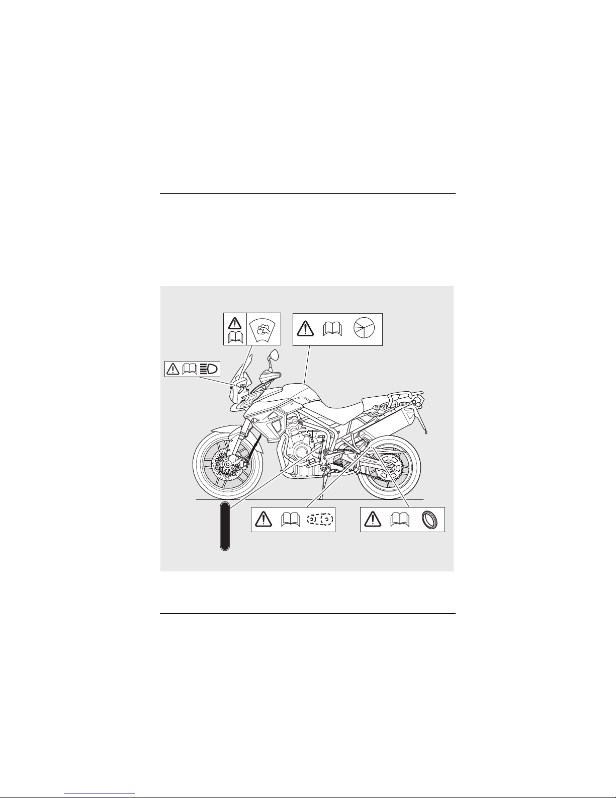
Warning Labels
WARNING LABELS
The labels detailed on this and the following pages draw your attention to important
safety information in this handbook. Before riding, ensure that all riders have
understood and complied with all the information to which these labels relate.
Warning Label Locations
cinf_4
6
5
4
3
2
N
1
R.P.M.
Headlights
(page 147)
Windscreen
(page 153)
Running-In
(page 88)
Tyre s
(page 136)
Drive Chain
(page 121)
Gear
Position
(page 94)
Page 13
13
Warning Labels
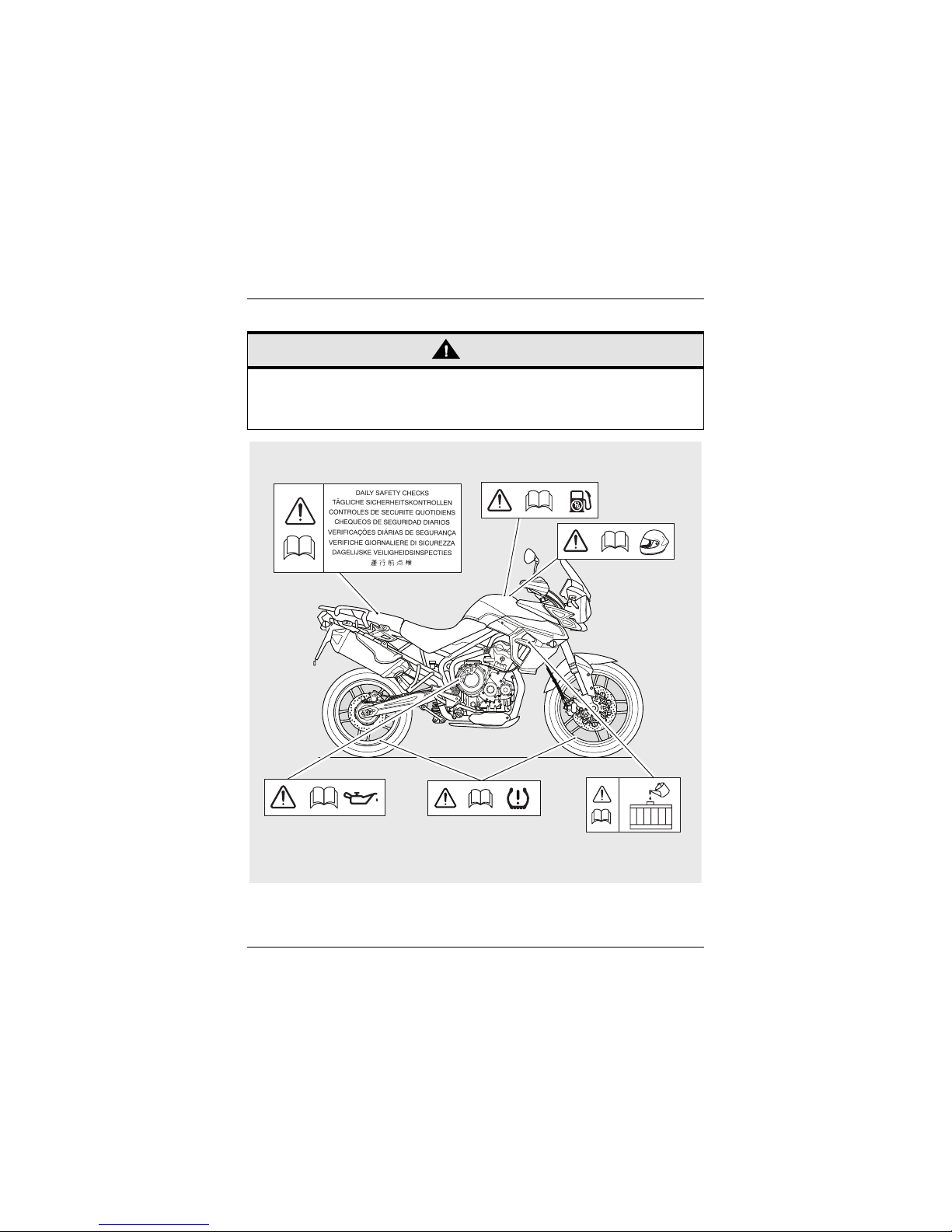
Warning Label Locations (continued)
Caution
All warning labels and decals, with the exception of the Running-in label, are fitted
to the motorcycle using a strong adhesive. In some cases, labels are installed prior
to an application of paint lacquer. Therefore, any attempt to remove the warning
labels will cause damage to the paintwork or bodywork.
cine_5
Daily Safety Checks
(page 89)
Helmet
(page 7)
Unleaded Fuel
(page 70)
Engine Oil
(page 114)
Coolant
(page 117)
TPMS
(if fitted)
(page 67)
Page 14
Parts Identification
14
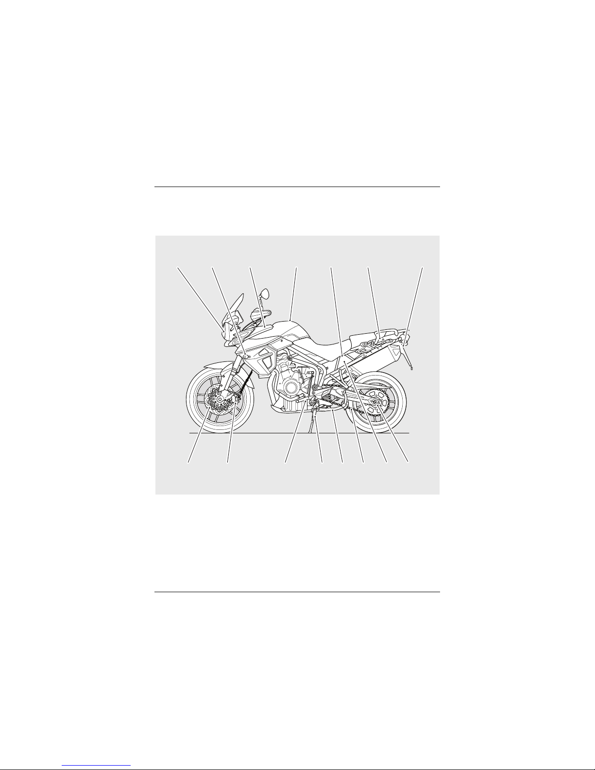
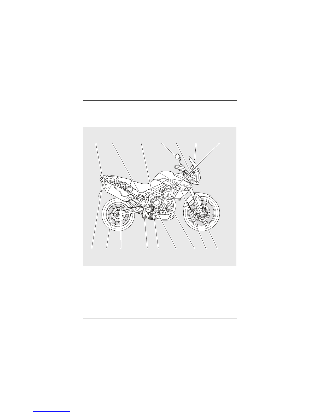
PARTS IDENTIFICATION
Tiger XRX
1. Headlight
2. Front direction indicator
3. Electrical accessory socket
4. Fuel tank and fuel filler cap
5. Battery and fuse boxes
6. Tool kit/Accessory U-lock storage
location
7. S e a t l o c k
8. Rear wheel adjuster
9. Electrical auxiliary socket
10. Drive chain
11. Centre stand
12. Side stand
13. Gear change pedal
14. Front brake caliper
15. Front brake disc
cinf_5
2 3 4 5 6 7
14
13 12 10
8
15
1
9
11
Page 15
Parts Identification
15
PARTS IDENTIFICATION
Tiger XRX (continued)
16. Rear light
17. Rear brake fluid reservoir
18. Oil filler cap
19. Mirror
20. Headlight adjuster
21. Windscreen
22. Coolant expansion tank
23. Front fork
24. Radiator/Coolant pressure cap
25. Clutch cable
26. Engine oil level sight glass
27. Rear brake pedal
28. Rear suspension spring preload
adjuster
29. Rear brake caliper
30. Rear brake disc
31. Rear direction indicator
17 18 19 20 21 22
28
27 26 25 2430 29
16
23
31
Page 16
Parts Identification
16
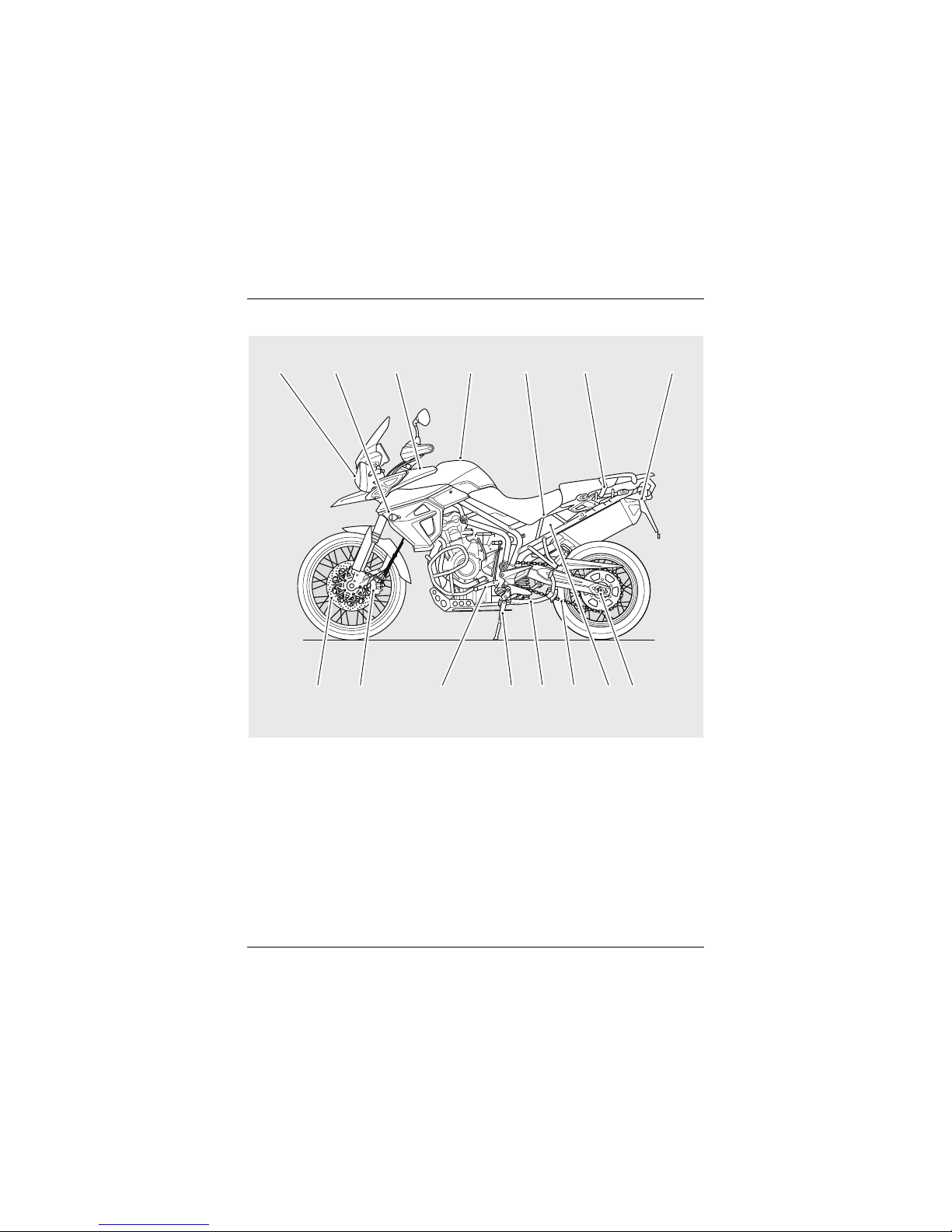
Tiger XCX
1. Headlight
2. Front direction indicator
3. Electrical accessory socket
4. Fuel tank and fuel filler cap
5. Battery and fuse boxes
6. Tool kit/Accessory U-lock storage
location
7. S e a t l o c k
8. Rear wheel adjuster
9. Electrical auxiliary socket
10. Drive chain
11. Centre stand
12. Side stand
13. Gear change pedal
14. Front brake caliper
15. Front brake disc
2 3 4 5 6 7
14
13 12 9 815
1
10
11
Page 17
Parts Identification
17
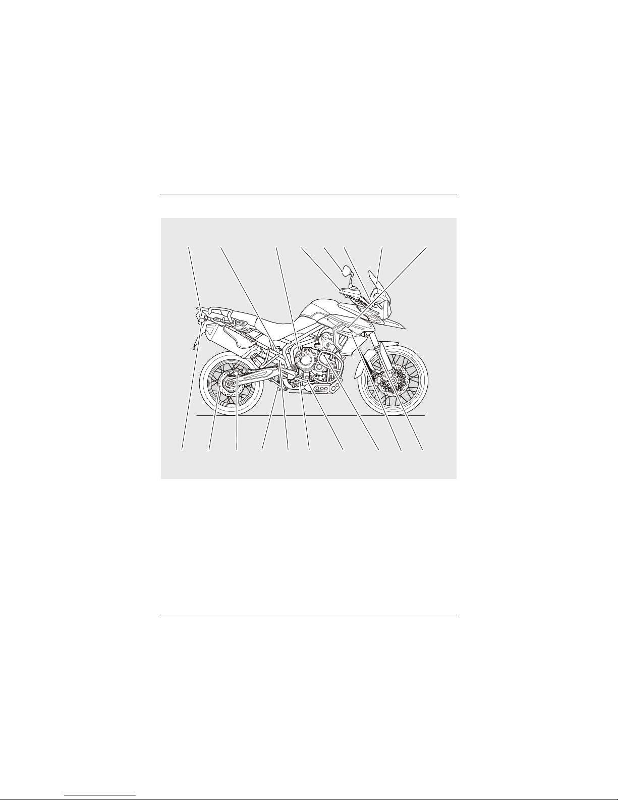
Tiger XCX (continued)
16. Rear light
17. Rear brake fluid reservoir
18. Oil filler cap
19. Handguards
20. Mirror
21. Headlight adjuster
22. Windscreen
23. Coolant expansion tank
24. Front fork
25. Radiator/Coolant pressure cap
26. Clutch cable
27. Engine oil level sight glass
28. Rear brake pedal
29. Rear suspension rebound damping
adjuster
30. Rear suspension preload adjuster
31. Rear brake caliper
32. Rear brake disc
33. Rear direction indicator
17 18 20 21 22 23
29
28 27 26 2531 30
16
24
19
32
33
Page 18
Parts Identification
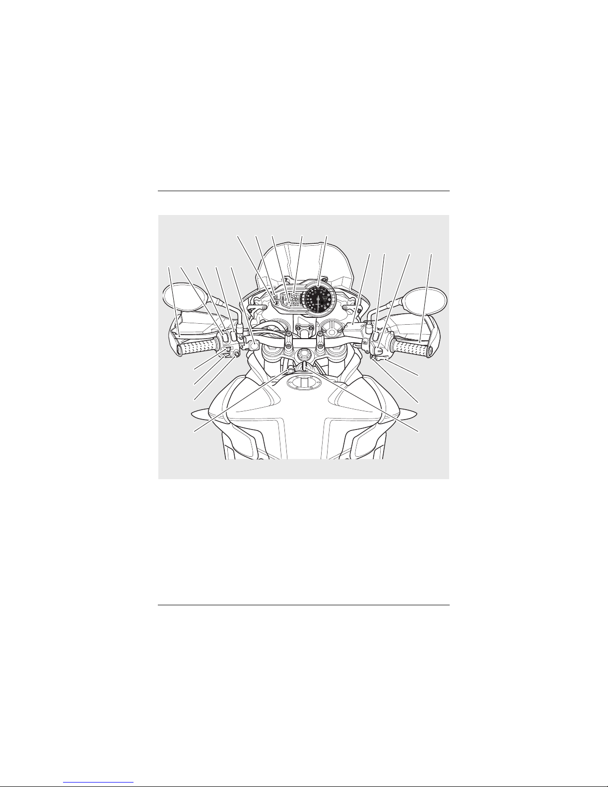
18
All Models (Tiger XCX shown)
1. Clutch lever
2. Headlight dip switch
3. Passing button
4. Instrument SCROLL button
5. Heated grip switch (if fitted)
6. Hazard warning light button
7. MODE button
8. Trip computer display
9. Speedometer
10. Tachometer
11. Front brake fluid reservoir
12. Engine stop switch
13. Cruise control adjust button
14. Front brake lever
15. Starter button
16. Cruise control ON/OFF button
17. Ignition switch
18. Electrical accessory socket
19. Instrument SET button
20. Horn button
21. Direction indicator switch
TC
TC
cink
12 3 4 5
678
9
10
11 12 13 14
15
16
1718
19
20
21
Page 19
Serial Numbers
19
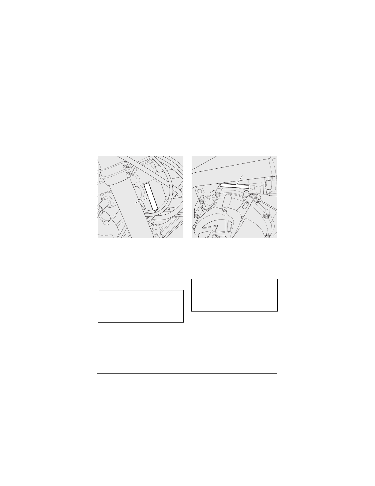
SERIAL NUMBERS
Vehicle Identification Number
(VIN)
1. VIN number
The Vehicle Identification Number (VIN) is
stamped into the steering head area of
the frame. It is also displayed on a plate,
riveted to the frame, below the pillion
seat.
Record the vehicle identification number
in the space provided below.
Engine Serial Number
1. Engine serial number
The engine serial number is stamped on
the engine crankcase, immediately above
the clutch cover.
Record the engine serial number in the
space provided below.
1
cgiv
1
cgjf
Page 20

Serial Numbers
20
This page intentionally left blank
Page 21

21
General Information
GENERAL INFORMATION
Table of Contents
Instrument Panel Layout . . . . . . . . . . . . . . . . . . . . . . . . . . . . . . . . . . . . . . . . . . . . . . . . . . 25
Warning Lights . . . . . . . . . . . . . . . . . . . . . . . . . . . . . . . . . . . . . . . . . . . . . . . . . . . . . . . . . . . 26
Direction Indicators . . . . . . . . . . . . . . . . . . . . . . . . . . . . . . . . . . . . . . . . . . . . . . . . . . . . 26
Neutral. . . . . . . . . . . . . . . . . . . . . . . . . . . . . . . . . . . . . . . . . . . . . . . . . . . . . . . . . . . . . . . 26
High Beam. . . . . . . . . . . . . . . . . . . . . . . . . . . . . . . . . . . . . . . . . . . . . . . . . . . . . . . . . . . .26
Low Fuel . . . . . . . . . . . . . . . . . . . . . . . . . . . . . . . . . . . . . . . . . . . . . . . . . . . . . . . . . . . . . 26
Cruise Control Light. . . . . . . . . . . . . . . . . . . . . . . . . . . . . . . . . . . . . . . . . . . . . . . . . . . . 26
ABS (Anti-Lock Brake System) Warning light . . . . . . . . . . . . . . . . . . . . . . . . . . . . . . 27
Alarm/Immobiliser Indicator Light. . . . . . . . . . . . . . . . . . . . . . . . . . . . . . . . . . . . . . . . 27
Triumph Traction Control (TTC) Disabled Warning Light . . . . . . . . . . . . . . . . . . . . . 28
Triumph Traction Control (TTC) Indicator Light . . . . . . . . . . . . . . . . . . . . . . . . . . . . . 28
Engine Management System Malfunction Indicator Light (MIL). . . . . . . . . . . . . . . 29
High Coolant Temperature Warning Light. . . . . . . . . . . . . . . . . . . . . . . . . . . . . . . . . 30
Low Oil Pressure Warning Light . . . . . . . . . . . . . . . . . . . . . . . . . . . . . . . . . . . . . . . . . 30
Tyre Pressure Warning Light (If Fitted) . . . . . . . . . . . . . . . . . . . . . . . . . . . . . . . . . . . 31
Frost Symbol. . . . . . . . . . . . . . . . . . . . . . . . . . . . . . . . . . . . . . . . . . . . . . . . . . . . . . . . . . 31
Low Battery Warning . . . . . . . . . . . . . . . . . . . . . . . . . . . . . . . . . . . . . . . . . . . . . . . . . . 32
Speedometer and Odometer . . . . . . . . . . . . . . . . . . . . . . . . . . . . . . . . . . . . . . . . . . . . . . . . 33
Tachometer . . . . . . . . . . . . . . . . . . . . . . . . . . . . . . . . . . . . . . . . . . . . . . . . . . . . . . . . . . . . . . 33
Gear Position Display . . . . . . . . . . . . . . . . . . . . . . . . . . . . . . . . . . . . . . . . . . . . . . . . . . . . . .33
Coolant Temperature Gauge . . . . . . . . . . . . . . . . . . . . . . . . . . . . . . . . . . . . . . . . . . . . . . . . 34
Fuel Gauge . . . . . . . . . . . . . . . . . . . . . . . . . . . . . . . . . . . . . . . . . . . . . . . . . . . . . . . . . . . . . . . 35
Service Interval Indicator . . . . . . . . . . . . . . . . . . . . . . . . . . . . . . . . . . . . . . . . . . . . . . . . . . 35
Hazard Warning Lights . . . . . . . . . . . . . . . . . . . . . . . . . . . . . . . . . . . . . . . . . . . . . . . . . . . . 36
Trip Computer . . . . . . . . . . . . . . . . . . . . . . . . . . . . . . . . . . . . . . . . . . . . . . . . . . . . . . . . . . . . 36
Trip Meters . . . . . . . . . . . . . . . . . . . . . . . . . . . . . . . . . . . . . . . . . . . . . . . . . . . . . . . . . . . 37
Trip Meter Reset . . . . . . . . . . . . . . . . . . . . . . . . . . . . . . . . . . . . . . . . . . . . . . . . . . . . . . 37
Information Menu . . . . . . . . . . . . . . . . . . . . . . . . . . . . . . . . . . . . . . . . . . . . . . . . . . . . . 37
Setup Menu . . . . . . . . . . . . . . . . . . . . . . . . . . . . . . . . . . . . . . . . . . . . . . . . . . . . . . . . . . . . . . 40
RIdER . . . . . . . . . . . . . . . . . . . . . . . . . . . . . . . . . . . . . . . . . . . . . . . . . . . . . . . . . . . . . . . . 40
Clock Adjustment – t-SEt . . . . . . . . . . . . . . . . . . . . . . . . . . . . . . . . . . . . . . . . . . . . . . . 41
Auto – Self-cancelling Direction Indicators – Ind . . . . . . . . . . . . . . . . . . . . . . . . . . . 42
Page 22

22
General Information
Service Interval Announcement – SIA . . . . . . . . . . . . . . . . . . . . . . . . . . . . . . . . . . . . 42
Changing Units – UnitS (Imperial, US or Metric) . . . . . . . . . . . . . . . . . . . . . . . . . . . . 42
Return . . . . . . . . . . . . . . . . . . . . . . . . . . . . . . . . . . . . . . . . . . . . . . . . . . . . . . . . . . . . . . . 43
Riding Modes . . . . . . . . . . . . . . . . . . . . . . . . . . . . . . . . . . . . . . . . . . . . . . . . . . . . . . . . . . . . . 44
MODE button . . . . . . . . . . . . . . . . . . . . . . . . . . . . . . . . . . . . . . . . . . . . . . . . . . . . . . . . . 44
ROAD Mode. . . . . . . . . . . . . . . . . . . . . . . . . . . . . . . . . . . . . . . . . . . . . . . . . . . . . . . . . . . 44
OFF ROAD Mode. . . . . . . . . . . . . . . . . . . . . . . . . . . . . . . . . . . . . . . . . . . . . . . . . . . . . . . 45
RIDER Mode . . . . . . . . . . . . . . . . . . . . . . . . . . . . . . . . . . . . . . . . . . . . . . . . . . . . . . . . . . 45
Riding Mode Selection. . . . . . . . . . . . . . . . . . . . . . . . . . . . . . . . . . . . . . . . . . . . . . . . . . 46
Selecting a Riding Mode – with the Motorcycle Stationary . . . . . . . . . . . . . . . . . . 47
Selecting a Riding Mode – when Riding the Motorcycle . . . . . . . . . . . . . . . . . . . . . 48
Setting the RIDER Mode Options. . . . . . . . . . . . . . . . . . . . . . . . . . . . . . . . . . . . . . . . . 50
Cruise Control . . . . . . . . . . . . . . . . . . . . . . . . . . . . . . . . . . . . . . . . . . . . . . . . . . . . . . . . . . . . 53
Activating Cruise Control . . . . . . . . . . . . . . . . . . . . . . . . . . . . . . . . . . . . . . . . . . . . . . . 54
Resuming the Cruise Control Set Speed . . . . . . . . . . . . . . . . . . . . . . . . . . . . . . . . . . 55
Increasing Speed while in Cruise Control. . . . . . . . . . . . . . . . . . . . . . . . . . . . . . . . . . 56
Decreasing Speed while in Cruise Control . . . . . . . . . . . . . . . . . . . . . . . . . . . . . . . . . 56
Deactivating Cruise Control . . . . . . . . . . . . . . . . . . . . . . . . . . . . . . . . . . . . . . . . . . . . . 56
Ignition . . . . . . . . . . . . . . . . . . . . . . . . . . . . . . . . . . . . . . . . . . . . . . . . . . . . . . . . . . . . . . . . . . 57
Ignition Key. . . . . . . . . . . . . . . . . . . . . . . . . . . . . . . . . . . . . . . . . . . . . . . . . . . . . . . . . . . 57
Engine Immobiliser. . . . . . . . . . . . . . . . . . . . . . . . . . . . . . . . . . . . . . . . . . . . . . . . . . . . . 57
Ignition Switch/Steering Lock . . . . . . . . . . . . . . . . . . . . . . . . . . . . . . . . . . . . . . . . . . . 58
Ignition Switch Positions . . . . . . . . . . . . . . . . . . . . . . . . . . . . . . . . . . . . . . . . . . . . . . . 58
Right Handlebar Switches . . . . . . . . . . . . . . . . . . . . . . . . . . . . . . . . . . . . . . . . . . . . . . . . . . 59
Engine Stop Switch . . . . . . . . . . . . . . . . . . . . . . . . . . . . . . . . . . . . . . . . . . . . . . . . . . . . 59
Starter Button . . . . . . . . . . . . . . . . . . . . . . . . . . . . . . . . . . . . . . . . . . . . . . . . . . . . . . . . 59
Cruise Control ON/OFF Button. . . . . . . . . . . . . . . . . . . . . . . . . . . . . . . . . . . . . . . . . . . 59
Cruise Control Adjust Button. . . . . . . . . . . . . . . . . . . . . . . . . . . . . . . . . . . . . . . . . . . . 59
Left Handlebar Switches . . . . . . . . . . . . . . . . . . . . . . . . . . . . . . . . . . . . . . . . . . . . . . . . . . . 60
Headlight Dip Switch . . . . . . . . . . . . . . . . . . . . . . . . . . . . . . . . . . . . . . . . . . . . . . . . . . . 60
Direction Indicator Switch . . . . . . . . . . . . . . . . . . . . . . . . . . . . . . . . . . . . . . . . . . . . . . 61
Horn Button . . . . . . . . . . . . . . . . . . . . . . . . . . . . . . . . . . . . . . . . . . . . . . . . . . . . . . . . . . 61
Pass Button . . . . . . . . . . . . . . . . . . . . . . . . . . . . . . . . . . . . . . . . . . . . . . . . . . . . . . . . . . 62
Instrument SCROLL button . . . . . . . . . . . . . . . . . . . . . . . . . . . . . . . . . . . . . . . . . . . . . 62
Instrument SET Button. . . . . . . . . . . . . . . . . . . . . . . . . . . . . . . . . . . . . . . . . . . . . . . . . 63
Heated Grips Switch (If Fitted). . . . . . . . . . . . . . . . . . . . . . . . . . . . . . . . . . . . . . . . . . . 63
Low Power Voltage Cut Off . . . . . . . . . . . . . . . . . . . . . . . . . . . . . . . . . . . . . . . . . . . . . 64
Page 23

23
General Information
Throttle Control. . . . . . . . . . . . . . . . . . . . . . . . . . . . . . . . . . . . . . . . . . . . . . . . . . . . . . . . . . . 64
Brake Use . . . . . . . . . . . . . . . . . . . . . . . . . . . . . . . . . . . . . . . . . . . . . . . . . . . . . . . . . . . .65
Brake and Clutch Lever Adjusters . . . . . . . . . . . . . . . . . . . . . . . . . . . . . . . . . . . . . . . . . . . 65
Triumph Traction Control (TTC) . . . . . . . . . . . . . . . . . . . . . . . . . . . . . . . . . . . . . . . . . . . . . . 66
Triumph Traction Control Settings . . . . . . . . . . . . . . . . . . . . . . . . . . . . . . . . . . . . . . . 67
Tyre Pressure Monitoring System (TPMS) (If Fitted) . . . . . . . . . . . . . . . . . . . . . . . . . . . . 67
TPMS Sensor ID Number. . . . . . . . . . . . . . . . . . . . . . . . . . . . . . . . . . . . . . . . . . . . . . . . 68
TPMS System Display . . . . . . . . . . . . . . . . . . . . . . . . . . . . . . . . . . . . . . . . . . . . . . . . . . 69
TPMS Sensor Batteries. . . . . . . . . . . . . . . . . . . . . . . . . . . . . . . . . . . . . . . . . . . . . . . . . 69
TPMS Symbol . . . . . . . . . . . . . . . . . . . . . . . . . . . . . . . . . . . . . . . . . . . . . . . . . . . . . . . . . 69
TPMS Tyre Pressures . . . . . . . . . . . . . . . . . . . . . . . . . . . . . . . . . . . . . . . . . . . . . . . . . . 70
Replacement Tyres . . . . . . . . . . . . . . . . . . . . . . . . . . . . . . . . . . . . . . . . . . . . . . . . . . . . 70
Fuel Requirement/Refuelling . . . . . . . . . . . . . . . . . . . . . . . . . . . . . . . . . . . . . . . . . . . . . . . 70
Fuel Grade. . . . . . . . . . . . . . . . . . . . . . . . . . . . . . . . . . . . . . . . . . . . . . . . . . . . . . . . . . . .70
Fuel Tank Cap . . . . . . . . . . . . . . . . . . . . . . . . . . . . . . . . . . . . . . . . . . . . . . . . . . . . . . . . . 72
Filling the Fuel Tank. . . . . . . . . . . . . . . . . . . . . . . . . . . . . . . . . . . . . . . . . . . . . . . . . . . . 72
Handlebar Adjustment. . . . . . . . . . . . . . . . . . . . . . . . . . . . . . . . . . . . . . . . . . . . . . . . . . . . . 73
Stands . . . . . . . . . . . . . . . . . . . . . . . . . . . . . . . . . . . . . . . . . . . . . . . . . . . . . . . . . . . . . . . . . . 75
Side stand . . . . . . . . . . . . . . . . . . . . . . . . . . . . . . . . . . . . . . . . . . . . . . . . . . . . . . . . . . . . 75
Centre Stand (If Fitted) . . . . . . . . . . . . . . . . . . . . . . . . . . . . . . . . . . . . . . . . . . . . . . . . . 75
Seats. . . . . . . . . . . . . . . . . . . . . . . . . . . . . . . . . . . . . . . . . . . . . . . . . . . . . . . . . . . . . . . . . . . . 76
Seat Care. . . . . . . . . . . . . . . . . . . . . . . . . . . . . . . . . . . . . . . . . . . . . . . . . . . . . . . . . . . . . 76
Pillion Seat . . . . . . . . . . . . . . . . . . . . . . . . . . . . . . . . . . . . . . . . . . . . . . . . . . . . . . . . . . . 76
Rider's Seat. . . . . . . . . . . . . . . . . . . . . . . . . . . . . . . . . . . . . . . . . . . . . . . . . . . . . . . . . . .78
Rider's Seat Height Adjustment . . . . . . . . . . . . . . . . . . . . . . . . . . . . . . . . . . . . . . . . . 78
Adjustable Windscreen (If Fitted). . . . . . . . . . . . . . . . . . . . . . . . . . . . . . . . . . . . . . . . . . . . 79
Tool Kit and Handbook. . . . . . . . . . . . . . . . . . . . . . . . . . . . . . . . . . . . . . . . . . . . . . . . . . . . . 80
Helmet Hook . . . . . . . . . . . . . . . . . . . . . . . . . . . . . . . . . . . . . . . . . . . . . . . . . . . . . . . . . . . . . 80
Electrical Accessory Socket . . . . . . . . . . . . . . . . . . . . . . . . . . . . . . . . . . . . . . . . . . . . . . . . 81
Electrical Auxiliary Socket . . . . . . . . . . . . . . . . . . . . . . . . . . . . . . . . . . . . . . . . . . . . . . . . . . 82
Pannier System (If Fitted) . . . . . . . . . . . . . . . . . . . . . . . . . . . . . . . . . . . . . . . . . . . . . . . . . . 82
To Remove Each Pannier: . . . . . . . . . . . . . . . . . . . . . . . . . . . . . . . . . . . . . . . . . . . . . . . 83
To Install Each Pannier: . . . . . . . . . . . . . . . . . . . . . . . . . . . . . . . . . . . . . . . . . . . . . . . . . 83
Pannier Operation . . . . . . . . . . . . . . . . . . . . . . . . . . . . . . . . . . . . . . . . . . . . . . . . . . . . . 84
Page 24

General Information
24
Triumph Accessory D-lock Storage . . . . . . . . . . . . . . . . . . . . . . . . . . . . . . . . . . . . . . . . . . 87
Running-In. . . . . . . . . . . . . . . . . . . . . . . . . . . . . . . . . . . . . . . . . . . . . . . . . . . . . . . . . . . . . . . 88
Safe Operation. . . . . . . . . . . . . . . . . . . . . . . . . . . . . . . . . . . . . . . . . . . . . . . . . . . . . . . . . . . . 89
Daily Safety Checks . . . . . . . . . . . . . . . . . . . . . . . . . . . . . . . . . . . . . . . . . . . . . . . . . . . . 89
Page 25
General Information
25
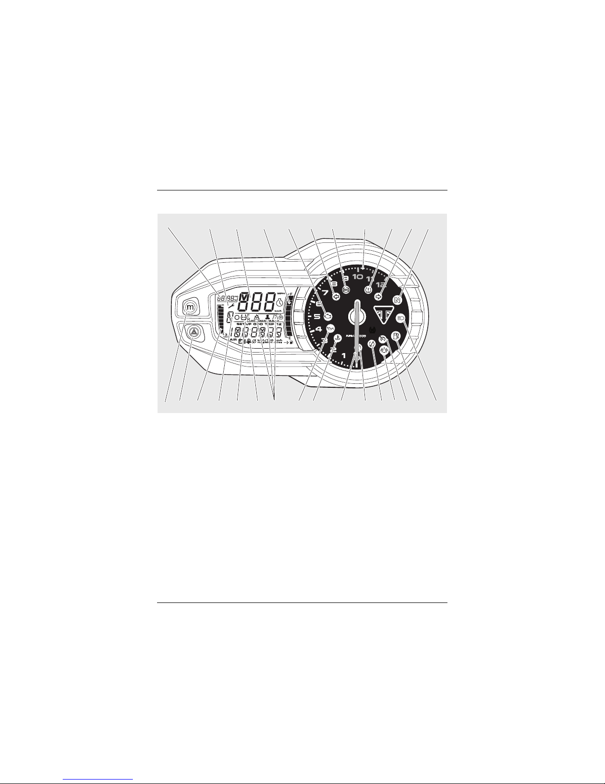
Instrument Panel Layout
1. Clock
2. Service interval indicator
3. Speedometer
4. Fuel gauge
5. Engine management malfunction
indicator light
6. Left hand direction indicator light
7. A B S wa r ni n g l ig h t
8. Tachometer red zone
9. Tyre pressure warning light (if Tyre
Pressure Monitoring System (TPMS)
is fitted) (TPMS is not available on
Tiger XC
X models)
10. Right hand direction indicator light
11. Neutral indicator light
12. High beam indicator light
13. Low fuel level indicator light
14. Cruise control light
15. Alarm/immobiliser status indicator
light (alarm is an accessory kit)
16. Traction control disabled warning
light
17. Traction control indicator light
18. Tachometer
19. High coolant temperature warning
light
20. Low oil pressure warning light
21. Riding modes
22. Frost symbol
23. Tyre pressure display (if Tyre
Pressure Monitoring System (TPMS)
is fitted) (TPMS is not available on
Tiger XC
X models)
24. Selected gear
25. Coolant temperature gauge
26. Hazard warning lights button
27. MODE button
TC
TC
2425 2023 22 21 1819 17 141516 13 1226
21 3 4567 8 91011
27
Page 26
General Information
26
Warning Lights
Note:
• When the ignition is switched on, the
instrument warning lights will
illuminate for 1.5 seconds and will
then go off (except those which
remain on until the engine starts, as
described in the following pages).
Direction Indicators
When the direction indicator
switch is pushed to the left or
right, the direction indicator
light will flash on and off at the same
speed as the direction indicators.
Neutral
The neutral warning light
indicates when the transmission
is in neutral (no gear selected).
The warning light will illuminate when
the transmission is in neutral with the
ignition switch in the ON position.
High Beam
When the ignition is switched
on and the headlight dip switch
is set to high beam, the high
beam warning light will illuminate.
Low Fuel
The low fuel indicator will
illuminate when there are
approximately 4.0 litres of fuel
remaining in the tank.
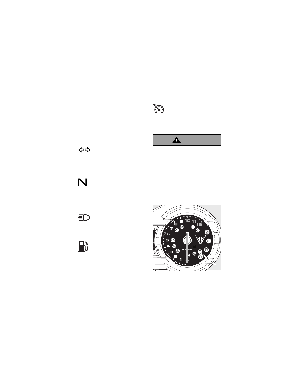
Cruise Control Light
The cruise control can only be
activated when the motorcycle
is travelling at a speed between
30to 100mph (48to 160km/h) and is in
4
th
gear or higher. When activated, the
cruise control light in the tachometer
will be illuminated (see page 53).
1. Cruise control light
Warning
Cruise control must only be used
where you can ride safely at a steady
speed.
Cruise control should not be used
when riding in heavy traffic, on roads
with sharp/blind bends or when they
are slippery.
Using cruise control in heavy traffic,
on roads with sharp/blind bends or
when they are slippery, may result in
loss of motorcycle control and an
accident.
TC
TC
1
Page 27
General Information
27
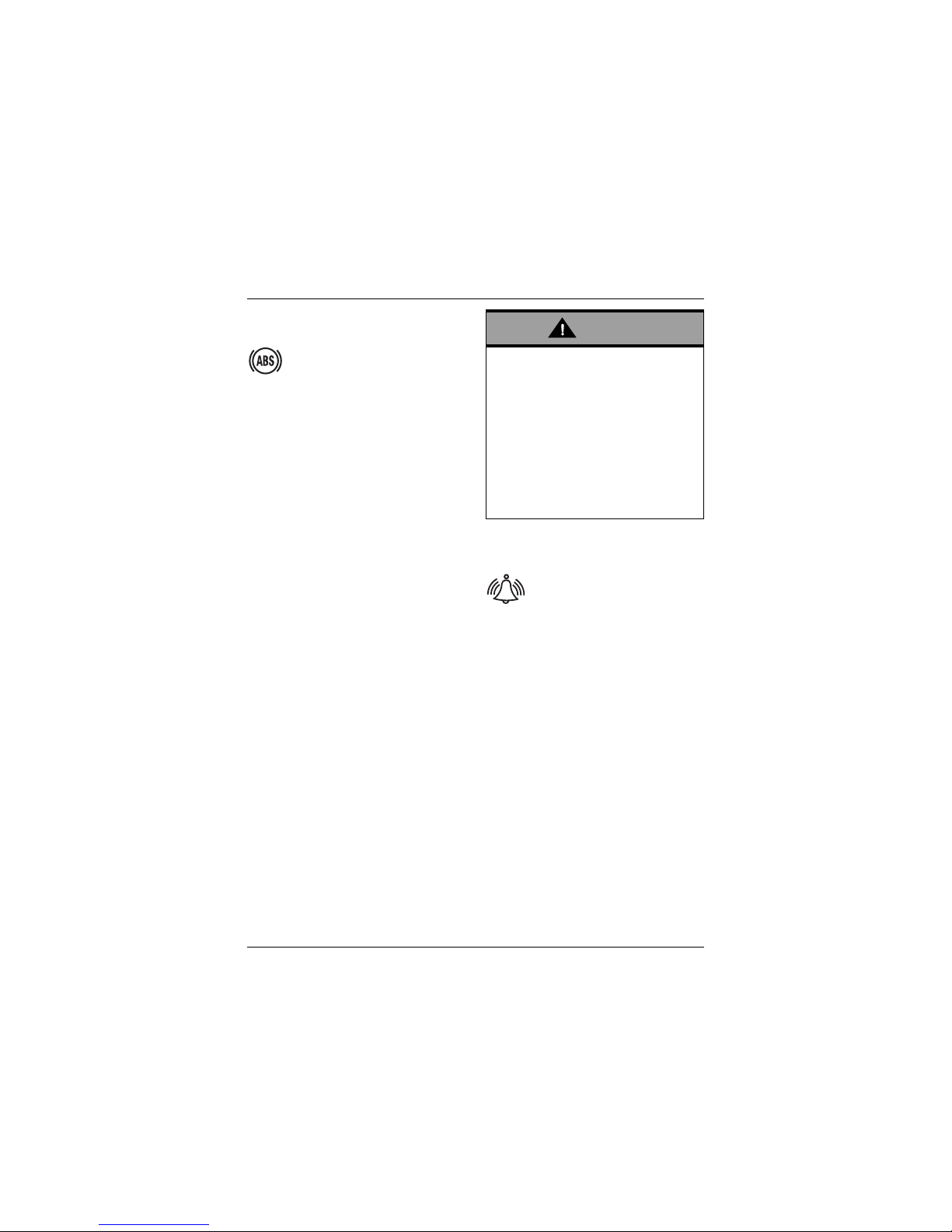
ABS (Anti-Lock Brake System)
Warning light
When the ignition switch is
turned to the ON position, it is
normal that the ABS warning
light will flash on and off. The light will
continue to flash after engine start-up
until the motorcycle first reaches a
speed exceeding 6 mph (10 km/h) when
it will go off.
Note:
• Cruise control and traction control
will not function if there is a
malfunction with the ABS system.
The warning lights for the ABS,
traction control and the MIL will be
illuminated.
The warning light should not illuminate
again until the engine is restarted
unless there is a fault, or:
• OFF ROAD Mode is selected – the
warning light will flash slowly (see
page 45).
•RIDER Mode is selected with ABS set
to Off Road – the warning light will
flash slowly (see page 45).
•RIDER Mode is selected with ABS set
to Off – the warning light will remain
illuminated (see page 45).
If the warning light becomes illuminated
at any other time while riding it indicates
that the ABS has a malfunction that
requires investigation.
See also Braking on page 95.
Alarm/Immobiliser Indicator Light
This Triumph model is fitted
with an engine immobiliser
which is activated when the
ignition switch is turned to the
OFF position. If the motorcycle is fitted
with a Genuine Triumph Accessory
alarm, the immobiliser will operate as
normal but the alarm/immobiliser light
will operate as described below.
With Alarm Fitted
The alarm/immobiliser light will only
illuminate when the conditions described
in the Genuine Triumph Accessory alarm
instructions are met.
Without Alarm Fitted
When the ignition switch is turned to
the OFF position, the alarm/immobiliser
light will flash on and off for 24 hours to
show that the engine immobiliser is on.
When the ignition switch is turned to
the ON position the immobiliser and the
indicator light will be off.
Warning
If the ABS is not functioning, the brake
system will continue to function as a
non-ABS braking system. Do not
continue to ride for longer than is
necessary with the warning light
illuminated. Contact an authorised
Triumph dealer as soon as possible to
have the fault checked and rectified.
In this situation braking too hard will
cause the wheels to lock resulting in
loss of motorcycle control and an
accident.
Page 28
General Information
28
If the indicator light remains on it
indicates that the immobiliser has a
malfunction that requires investigation.
Contact an authorised Triumph dealer as
soon as possible to have the fault
checked and rectified.
Triumph Traction Control (TTC)
Disabled Warning Light
The TTC disabled warning light
will illuminate when the RIDER
Mode is selected with TTC set
to Off (see page 45);
• TTC set to Off – the warning light is
illuminated.
• TTC set to Road or Off Road – the
warning light is off.
If the warning light becomes illuminated
at any other time while riding, it
indicates that the TTC has a malfunction
that requires investigation.
1. Traction control disabled warning
light
Triumph Traction Control (TTC)
Indicator Light
The TTC indicator light is used
to indicate that the traction
control system is active and is
working to limit rear wheel slip
during periods of hard acceleration or
under wet or slippery road conditions.
TTC Indicator Light Operation:
ROAD or RIDER Mode selected with TTC
set to Road:
• Under normal riding conditions the
indicator light will remain off.
• The indicator light will flash rapidly
when the traction control system is
working to limit rear wheel slip
during periods of hard acceleration
or under wet or slippery road
conditions.
OFF ROAD or RIDER Mode selected with
TTC set to Off Road:
• Under normal riding conditions, the
indicator light will flash slowly to
indicate that the TTC system is set
to Off Road.
• The TTC indicator light will flash
rapidly when the traction control
system is working to limit rear wheel
slip during periods of hard
acceleration or under wet or slippery
road conditions.
RIDER Mode selected with TTC set to Off:
• The indicator light will not illuminate.
Instead the TTC disabled warning
light will be illuminated (see page 28).
For full details on ROAD, OFF ROAD and
RIDER Modes, see Riding Modes on
page 44.
TC
TC
TC
1
TC
Page 29
General Information
29
Note:
• Traction control will not function if
there is a malfunction with the ABS
system. The warning lights for the
ABS, traction control and the MIL will
be illuminated.
1. Traction control indicator light
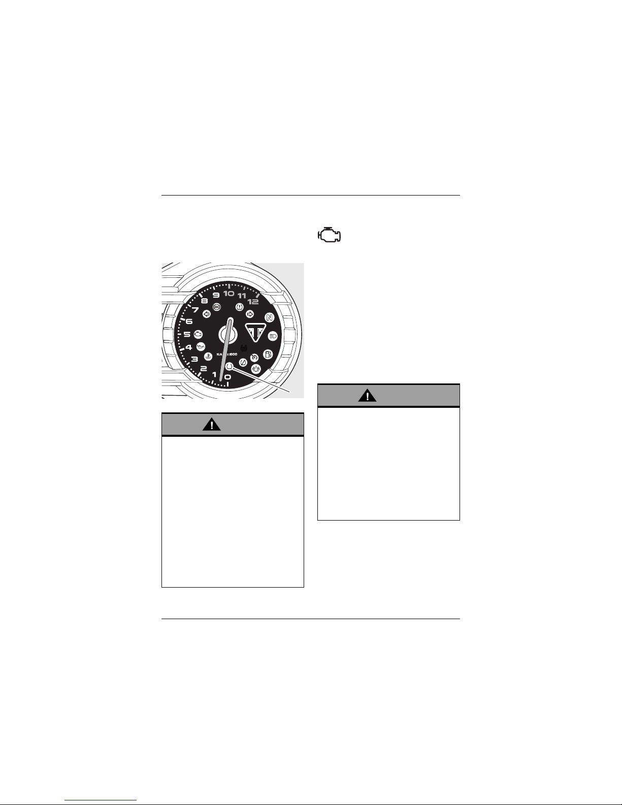
Engine Management System
Malfunction Indicator Light (MIL)
The Malfunction Indicator Light
(MIL) for the engine
management system illuminates
briefly when the ignition is switched on
(to indicate that it is working), but should
not become illuminated when the engine
is running.
If the MIL becomes illuminated when the
engine is running, this indicates that a
fault has occurred in one or more of the
systems controlled by the engine
management system. In such
circumstances, the engine management
system will switch to limp-home mode so
that the journey may be completed, if
the fault is not so severe that the engine
will not run.
Note:
• If the MIL flashes when the ignition
is switched on, contact an
authorised Triumph dealer as soon
as possible to have the situation
rectified. In these circumstances the
engine will not start.
Warning
If the traction control is not
functioning, care must be taken when
accelerating and cornering on
wet/slippery road surfaces to avoid
rear wheel spin. Do not continue to
ride for longer than is necessary with
the Engine Management System
Malfunction Indicator Light
(MIL) and
traction control warning lights
illuminated. Contact an authorised
Triumph dealer as soon as possible to
have the fault checked.
Hard acceleration and cornering in
this situation may cause the rear
wheel to spin resulting in loss of
motorcycle control and an accident.
TC
TC
1
Warning
Reduce speed and do not continue to
ride for longer than is necessary with
the MIL illuminated. The fault may
adversely affect engine performance,
exhaust emissions and fuel
consumption. Reduced engine
performance could cause a dangerous
riding condition, leading to loss of
motorcycle control and an accident.
Contact an authorised Triumph dealer
as soon as possible to have the fault
checked and rectified.
Page 30
General Information
30
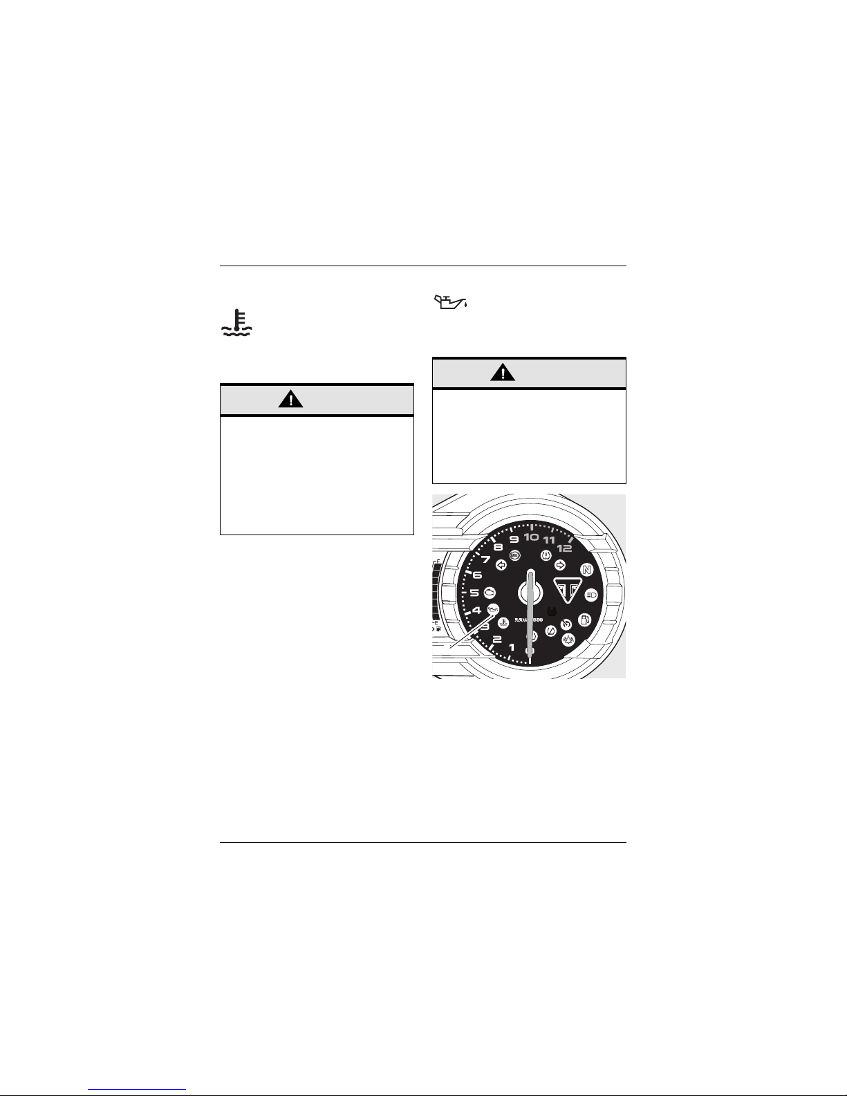
High Coolant Temperature Warning
Light
With the engine running, if the
engine coolant temperature
becomes dangerously high, the
high coolant temperature
warning light in the tachometer will
illuminate.
Low Oil Pressure Warning Light
With the engine running, if the
engine oil pressure becomes
dangerously low, the low oil pressure
warning light in the tachometer will
illuminate.
1. Low oil pressure warning light
The low oil pressure warning light in the
tachometer will illuminate if the ignition
is switched on without running the
engine.
Caution
Stop the engine immediately if the
high coolant temperature warning
light illuminates. Do not restart the
engine until the fault has been
rectified.
Severe engine damage will result from
running the engine when the high
coolant temperature warning light is
illuminated.
Caution
Stop the engine immediately if the low
oil pressure warning light illuminates.
Do not restart the engine until the
fault has been rectified.
Severe engine damage will result from
running the engine when the low oil
pressure warning light is illuminated.
TC
TC
1
Page 31

General Information
31
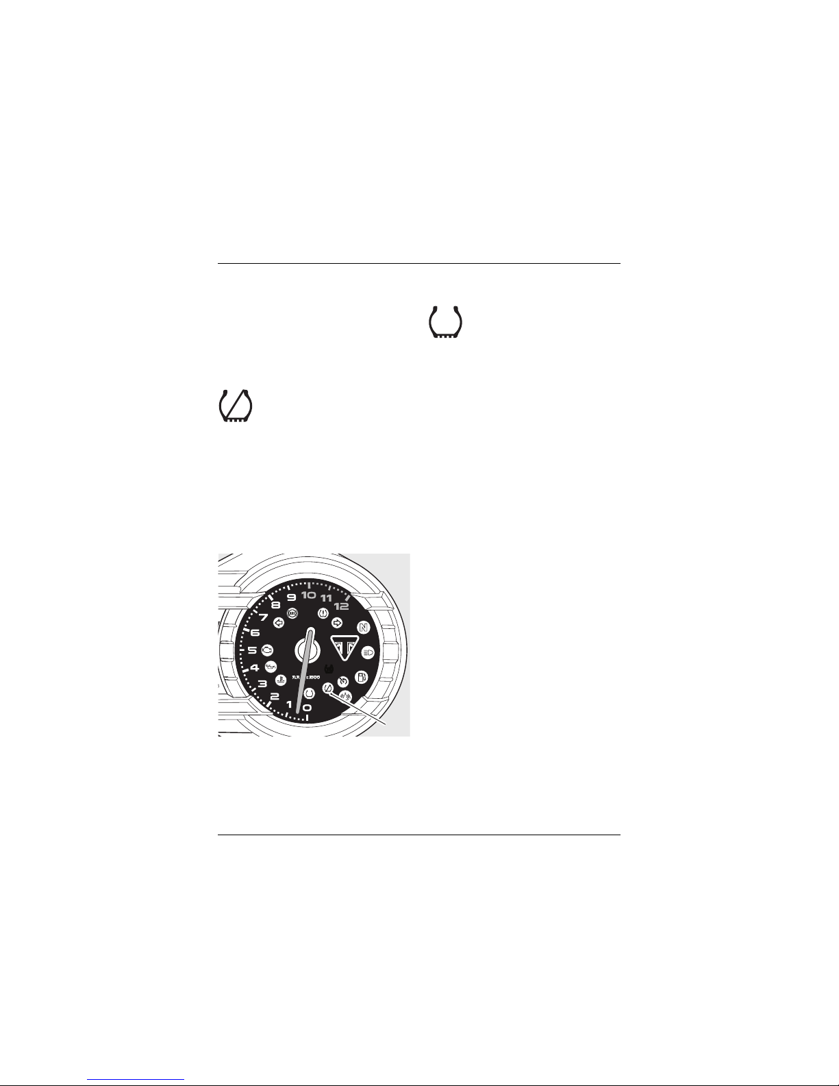
Tyre Pressure Warning Light
(If Fitted)
Note:
• TPMS is not available on Tiger XC
X
models.
The tyre pressure warning light
works in conjunction with the
tyre pressure monitoring
system (see page 70).
The warning light will only illuminate
when the front or rear tyre pressure is
below the recommended pressure. It will
not illuminate if the tyre is over inflated.
When the warning light is illuminated,
the TPMS symbol indicating which is the
deflated tyre and its pressure will
automatically be visible in the display
area.
1. TPMS symbol
2. Rear tyre, identified
3. Tyre pressure
4. Tyre pressure warning light
The tyre pressure at which the warning
light illuminates is temperature
compensated to 20°C but the numeric
pressure display associated with it is not
(see page 138). Even if the numeric
display seems at or close to the
standard tyre pressure when the
warning light is on, a low tyre pressure
is indicated and a puncture is the most
likely cause.
Frost Symbol
The frost symbol will illuminate
If the ambient air temperature
is 4°C (39°F) or lower.
The ambient air temperature is
displayed for four seconds upon
illumination of the frost symbol. The
display will then revert back to the
previous screen.
The frost symbol will remain illuminated
until the temperature rises to 6ºC (42ºF).
TC
TC
1
3
2
4
Warning
Stop the motorcycle if the tyre
pressure warning light illuminates. Do
not ride the motorcycle until the tyres
have been checked and the tyre
pressures are at their recommended
pressure when cold.
Page 32

General Information
32
The temperature display can be turned
off by pressing either the SET or SCROLL
buttons on the left hand switch housing.
The previous screen will be displayed
with the frost symbol illuminated until
the temperature rises to 6ºC (42ºF).
1. Frost symbol
2. Ambient air temperature
When the motorcycle is stationary the
heat of the engine may affect the
accuracy of the ambient temperature
display.
Once the motorcycle starts moving the
display will return to normal after a
short time.
Low Battery Warning
If items such as the heated grips and
accessory fog lights are fitted and are
on with the engine at idle, over a period
of time, the battery voltage may drop
below a predetermined voltage and
bAt Lo will be visible in the display
screen.
The display will remain on until one of
the following conditions is met:
• The charging system has charged
the battery
• Either the SCROLL or SET buttons on
the left hand switch housing has
been pressed
• The ignition switch has been turned
to the OFF position.
If necessary have the battery and
charging system checked by your
authorised Triumph dealer.
1. Display screen
Warning
Black ice (sometimes called clear ice)
can form at temperatures several
degrees above freezing (0°C (32°F)),
especially on bridges and in shaded
areas.
Always take extra care when the
temperatures are low and reduce
speed in potentially hazardous driving
conditions such as bad weather.
Excess speed, hard acceleration,
heavy braking or hard cornering when
roads are slippery may result in loss of
motorcycle control and an accident.
1
2
1
Page 33

General Information
33
Speedometer and Odometer
The digital speedometer indicates the
road speed of the motorcycle. The
read-out displays the motorcycle road
speed in increments of one mile (or
kilometre) per hour.
The electronic odometer and two trip
meters are available to view in the
display screen. For details of the
operation of the odometer and trip
meters see page 36.
Tachometer
The tachometer shows the engine speed
in revolutions per minute – rpm (r/min).
At the end of the tachometer range
there is the red zone.
Engine rpm (r/min) in the red zone is
above maximum recommended engine
speed and is also above the range for
best performance.
Gear Position Display
1. Gear position display
(neutral position displayed)
2. Gear position symbol
The gear position display indicates which
gear (one to six) has been engaged.
When the transmission is in neutral (no
gear selected), the display will show N.
1. Gear position display
(first gear shown)
Caution
Never allow engine rpm to enter the
red zone as severe engine damage
may result.
1
2
1
Page 34

General Information
34
Coolant Temperature Gauge
1. Coolant temperature gauge
The coolant temperature gauge
indicates the temperature of the engine
coolant.
When the ignition is switched on, all
eight bars of the display will be shown.
When the engine is started from cold
the display will show one bar. As the
temperature increases more bars in the
display will be shown. When the engine
is started from hot the display will show
the relevant number of bars, dependant
on engine temperature.
The normal temperature range is
between four and six bars. If the coolant
temperature becomes too high the
display will show eight bars and will start
to flash. The high coolant temperature
light in the tachometer will also be
illuminated.
1
Caution
Do not continue to run the engine if
either of the high temperature
warnings are displayed as severe
engine damage may result.
Page 35

General Information
35
Fuel Gauge
1. Fuel gauge
The fuel gauge indicates the amount of
fuel in the tank.
With the ignition switched on, the
number of bars shown in the display
indicates the level of fuel.
When the fuel tank is full all eight bars
are displayed and when empty, no bars
are displayed. Other gauge markings
indicate intermediate fuel levels between
full and empty.
When two bars are displayed the low
fuel warning light will illuminate,
five seconds later the display screen will
switch to the Range to Empty display
(see page 38). This indicates there are
approximately 4.0 litres of fuel remaining
in the tank and you should refuel at the
earliest opportunity.
After refuelling, the fuel gauge and
range to empty information will be
updated only while riding the
motorcycle. Depending on the riding
style, updating could take up to
five minutes.
Service Interval Indicator
1. Service indicator
2. Remaining distance
When the ignition is switched on and the
distance to the next service is 500 miles
(800 km) or less, the display will briefly
show the distance remaining before the
next service. If the service is overdue,
the distance will be displayed as a
negative number.
When the service has been carried out
by your authorised Triumph dealer, the
system will be reset.
When the remaining distance is 0 miles
(0 km) the service symbol will remain on
until the service has been carried out
and the system has been reset by your
authorised Triumph dealer. If the service
is overdue, the distance will be displayed
as a negative number.
1
2
1
Page 36

General Information
36
Hazard Warning Lights
To turn the hazard warning lights on or
off, press and release the hazard
warning light switch on the instruments.
The ignition must be switched ON for the
hazard warning lights to function.
The hazard warning lights will remain on
if the ignition is switched off, until the
hazard warning light switch is pressed
again.
1. Hazard warning light switch
Trip C o mpu t e r
1. SCROLL button, up
2. SCROLL button, down
3. SET button
To access the trip computer information,
press and release the SET button on the
left hand switch housing until the
desired display is visible. The display will
cycle through in the following order:
•Trip Meter1
•Trip Meter2
• Information
•Setup.
1
2
1
3
Page 37

General Information
37
Trip Meter s
1. Trip meter display
2. Trip meter 1 display
3. Trip meter 2 display
Press and release the SET button on the
left hand switch housing until the
desired trip meter is visible.
Press and release the SCROLL button on
the left hand switch housing. The display
will cycle through in the following order:
•Journey distance
•Journey time
• Average fuel consumption
• Average speed.
Each display provides the following
information:
Journey Distance
The total journey distance travelled
since the trip meter was last reset to
zero.
Journey Time
The total time elapsed since the trip
meter was last reset to zero.
Average Fuel Consumption
An indication of the average fuel
consumption since the trip meter was
last reset to zero. After being reset the
display will show dashes until
0.1 miles/km has been covered.
Average Speed
The average speed is calculated from
when the trip computer was last reset
to zero. After being reset the display will
show dashes until one mile/km has been
covered.
Trip Meter Reset
To reset either of the trip meters, select
and display the trip meter to be zeroed
then press and hold the SET button for
two seconds. After two seconds, all
items within the selected trip meter will
reset to zero.
Information Menu
To access the information menu, turn
the ignition to the ON position. Press
and release the SET button on the left
hand switch housing until InFo appears
in the display screen.
Note:
• InFo will appear in the display screen
for 0.5 seconds to indicate that the
information menu has been selected.
The display screen will then change
to display one of the items listed
below.
2
3
1
Page 38

General Information
38
Press and release the SCROLL button on
the left hand switch housing. The display
will scroll through the information menu
in the following order when pressing
down on the SCROLL button (it will scroll
through in the reverse order when
pressing up on the SCROLL button):
• Cruise set speed
•Range to empty
• Ambient air temperature
•Odometer
• Front tyre pressure (if TPMS is fitted
and activated, see page 67)
• Rear tyre pressure (if TPMS is fitted
and activated, see page 67)
• Instantaneous fuel consumption.
Each display provides the following
information:
Cruise Set Speed
If the cruise control is activated, this
display will show the road speed set for
cruise control. If the cruise control is not
activated, SEt--- will be visible in the
display area.
Range to Empty
This is an indication of the probable
distance that can be travelled on the
remaining fuel in the tank.
Ambient Air Temperature
The current ambient air temperature is
displayed in °C or °F.
To change the temperature from ºC
or ºF, see Changing Units on page 42.
Odometer
Shows the total distance that the
motorcycle has travelled.
Page 39

General Information
39
Front and Rear Tyre pressures (if TPMS
is fitted and activated, see page 67)
The front and rear tyre pressures are
displayed.
Front Tyre Pressure Shown
Instantaneous Fuel Consumption
An indication of the fuel consumption at
an instant in time. If the motorcycle is
stationary, --.- will be visible in the
display area.
To exit the information menu, press and
release the SET button until the desired
trip meter is displayed.
Warning
When the motorcycle is in motion, only
attempt to switch between the
information and trip meter display
modes or reset the trip meter under
the following conditions:
• At low speed
• In traffic free areas
• On straight and level roads or
surfaces
• In good road and weather
conditions.
Failure to observe this important
warning could lead to loss of
motorcycle control and an accident.
Page 40

General Information
40
Setup Menu
To access the setup menu; with the
motorcycle stationary and in neutral:
• Press and release the SET button on
the left hand switch housing until
SEtUP is visible in the display screen.
Press and release the SCROLL button
until the chosen menu item is visible.
Pressing the SET button allows the
displayed menu item to be edited.
1. SET button
2. SCROLL button
The display will scroll through the menu
in the following order when pressing
down on the SCROLL button (it will scroll
through in the reverse order when
pressing up on the SCROLL button):
• RIdER – RIDER Mode Setup
•t-SEt – Clock Adjustment
• Ind – Auto - Self-cancelling Direction
Indicators
• SIA – Service Interval Announcement
• UnitS – Changing Units (imperial,
metric or US)
• REtURn – Returns the instruments
to the main display.
Each menu item can be edited as follows:
RIdER
This menu allows the rider to select from
the various MAP, ABS and TTC options
that are available within the RIDER
Mode. For more information, refer to the
following sections:
• Riding Modes (see page 44)
• RIDER Mode (see page 45)
• Setting the RIDER Mode options (see
page 50).
1
2
Page 41

General Information
41
Clock Adjustment – t-SEt
To reset the clock; with the motorcycle
stationary and in neutral turn the
ignition to the ON position. Press and
release the SET button on the left hand
switch housing until SEtUP is visible in
the display screen.
Press and release the SCROLL button
until t-SEt is visible.
1. Time set
Press the SET button again and either
24 Hr or 12 Hr clock will be shown. Press
the SCROLL button to select the desired
clock display and then press the SET
button. The hour display will start to
flash and the word Hour is visible in the
display screen.
Note:
• The hour/minute display will
increase when pressing up on the
SCROLL button or decrease when
pressing down on the SCROLL
button.
To reset the hour display, ensure that
the hour display is still flashing and the
word Hour is visible. Press the SCROLL
button to change the setting. Each
individual button press will change the
setting by one digit. If the button is held,
the display will continuously scroll
through in single digit increments.
When the correct hour display is shown,
press the SET button. The minutes
display will begin to flash and the word
Min is visible in the display screen. The
minutes display is adjusted in the same
way as for the hours.
Once both hours and minutes are
correctly set, press the SET button to
confirm and t-SEt will be visible in the
display screen. Press the SCROLL button
until the display shows REtURn and
press the SELECT button, the odometer
in the trip 1 menu will be visible in the
display screen.
1. Clock display
2. Hours read-out
3. Minutes read-out
4. Display screen (Hour selected for
adjustment)
1
1
4
3
2
Page 42

General Information
42
Auto – Self-cancelling Direction
Indicators – Ind
This Triumph model has a self-cancelling
direction indicator function that can be
disabled or enabled.
To disable or enable the self-cancelling
function; with the motorcycle stationary
and in neutral, press and release the
SET button on the left hand switch
housing until SEtUP is visible in the
display screen.
Press and release the SCROLL button
until Ind is visible in the display screen.
Press and release the SET button and
Auto or MAnUAL will flash on and off.
Press and release the SCROLL button to
select Auto or MAnUAL then press the
SET button.
• Auto – The self-cancelling function is
on (see page 61).
• MAnUAL – The self-cancelling
function is off. The direction
indicators must be manually
cancelled (see page 61).
1. Auto selected
To exit the Auto – Self-cancelling
Direction Indicators menu, press and
release the SCROLL button until the
display shows REtURn and press the
select button. The trip 1 menu will be
visible in the display screen.
Service Interval Announcement –
SIA
Shows the total distance that the
motorcycle has remaining before a
service is required (see page 35).
Service Interval Announcement
Screen
Changing Units – UnitS (Imperial, US
or Metric)
Units has four selectable display modes.
Each display provides the following
information:
mpg (Imperial gallons)
The speedometer and odometer will read
in miles. The fuel consumption will be
measured in imperial gallons.
1
Page 43

General Information
43
mpg US (US gallons)
The speedometer and odometer will read
in miles. The fuel consumption will be
measured in US gallons.
L/100 km (Metric)
The speedometer and odometer will read
in kilometres. The fuel consumption will
be measured in litres of fuel per 100 km.
km/L (Metric)
The speedometer and odometer will read
in kilometres. The fuel consumption will
be measured in kilometres per litre of
fuel.
All Models
To access the units display; with the
motorcycle stationary and in neutral,
turn the ignition to the ON position.
Press and release the SET button on the
left hand switch housing until SEtUP is
visible in the display screen.
Press and release the SCROLL button
until UnitS is visible then press the SET
button.
1. Display screen
Press and release the SCROLL button
until the desired display is visible. The
display will scroll through in the
following order when pressing down on
the SCROLL button (it will scroll through
in the reverse order when pressing up
on the SCROLL button):
• mpg – Imperial gallons
• mpg US – US gallons
•L/100km – Metric
•km/L – Metric.
Tyre Pressure Units – Models with TPMS
fitted
Press the SET button and do not touch
the SCROLL or SET buttons again until
PSI or bAr is displayed. Press and
release the SCROLL button until the
desired tyre pressure units are visible.
Ambient Air Temperature Units – All
Models
Press the SET button and wait until ºC
or ºF is visible. Press and release the
SCROLL button until the desired
temperature unit is displayed. Press the
SET button and wait until UnitS is
displayed.
To exit, press the SCROLL button until
the display shows REtURn and press the
select button. The the trip 1 menu will be
visible in the display screen.
Return
Returns the instruments to the main
display.
1
Page 44

General Information
44
Riding Modes
The riding mode system allows
adjustment of the throttle response
(MAP), Anti-lock Brake System (ABS) and
Triumph Traction Control (TTC) settings
to suit differing road conditions and
rider preferences.
Riding modes can be conveniently
selected using the MODE button on the
instruments, whilst the motorcycle is
stationary or moving.
MODE button
1. MODE button
Pressing and releasing the MODE button
allows the rider to select a riding mode
(see page 46).
There are three riding modes available
for selection:
• ROAD Mode – non adjustable
• OFF ROAD Mode – non adjustable
• RIDER Mode – adjustable.
Pressing and holding the MODE button
allows the rider to access the RIDER
Mode setup menu (see page 50).
ROAD Mode
The ROAD Mode provides optimal
MAP, ABS and TTC settings for
normal road use.
1
System Settings
MAP Road – Standard throttle
response.
ABS Road – Optimal ABS setting
for road use.
TTC Road – Optimal TTC setting
for road use, allows minimal
rear wheel slip.
Warning
The OFF ROAD Mode is not intended
for normal, on-road riding.
Riding on-road with the OFF ROAD
Mode activated can produce instability
when braking if the ABS cuts in and
under acceleration if the TTC
intervenes, leading to loss of
motorcycle control and an accident.
Page 45

General Information
45
OFF ROAD Mode
The OFF ROAD Mode provides
optimal MAP, ABS and TTC
settings for light off-road
riding.
RIDER Mode
The RIDER Mode is fully adjustable
and allows the rider to select MAP,
ABS and TTC options to suit road
conditions or personal preferences.
The MAP, ABS and TTC options available
for selection are as follows:
System Settings
MAP Off Road – Optimal throttle
response setting for
off-road use.
ABS Off Road – Optimal ABS
setting for off-road use:
Front Wheel – The ABS
system allows increased
front wheel slip when
compared to the Road
setting.
Rear Wheel – The ABS
system is disabled for the
rear wheel, allowing it to lock
under heavy braking.
The ABS warning light will
flash slowly (see page 27).
TTC Off Road – TTC is set up for
off-road use, allowing
increased rear wheel slip
when compared to the Road
setting. The TTC indicator
light will flash slowly (see
page 28).
MAP Options
Rain Reduced throttle response
when compared to the Road
setting, for wet or slippery
conditions.
Road Standard throttle response.
Sport Increased throttle response
when compared to the Road
setting.
Off
Road
Optimal throttle response
setting for off-road use.
Warning
The OFF ROAD ABS and TTC options
are not intended for normal, on-road
riding.
Riding on-road with the Off Road ABS
and TTC options activated can
produce instability when braking if the
ABS cuts in and under acceleration if
the TTC intervenes, leading to loss of
motorcycle control and an accident.
Page 46

General Information
46
See page 50 for details on setting the
RIDER Mode options.
Riding Mode Selection
Riding modes may be selected when the
motorcycle is stationary or moving.
When the MODE button is pressed the
riding modes are displayed in the
following sequence:
•ROAD Mode
•OFF ROAD Mode
•RIDER Mode.
To allow the user to scroll between each
of the modes there is a one second
time-out to allow for further scrolling to
take place.
The selected mode is automatically
activated once the one second time-out
has elapsed, and the conditions for
switching modes have been met.
ABS Options
Road Optimal ABS setting for road
use.
Off
Road
Optimal ABS setting for
off-road use:
Front Wheel – The ABS
system allows increased
front wheel slip when
compared to the Road
setting.
Rear Wheel – The ABS
system is disabled for the
rear wheel, allowing it to lock
under heavy braking.
The ABS warning light will
flash slowly (see page 27).
Off ABS is turned off. The ABS
warning light will be
illuminated (see page 27).
TTC Options
Road Optimal TTC setting for road
use, allows minimal rear
wheel slip.
Off
Road
TTC is set up for off-road
use, allowing increased rear
wheel slip when compared to
the Road setting. The TTC
indicator light will flash
slowly (see page 28).
Off TTC is turned off. The TTC
disabled warning light will be
illuminated (see page 28).
Warning
After selecting a riding mode, operate
the motorcycle in an area free from
traffic to gain familiarity with the new
settings. Do not loan your motorcycle
to anyone as they may change the
riding mode settings from the one you
are familiar with, causing loss of
motorcycle control and an accident.
Page 47

General Information
47
Note:
• The riding mode will default to ROAD
when the ignition is switched ON if:
The OFF ROAD Mode was active the
last time the ignition was switched
off; or
The RIDER Mode was active the last
time the ignition was switched off
with ABS and/or TTC set to Off Road
or Off.
• Otherwise, the last selected riding
mode will be remembered and
activated when the ignition is
switched ON.
Selecting a Riding Mode – with the
Motorcycle Stationary
Note:
• If the ignition is switched on and the
engine not started, the instruments
will display the odometer for five
seconds. During this time, no mode
changes can be made.
Press and release the MODE button on
the instrument housing until the desired
riding mode is flashing in the display.
1. MODE button
2. Selected riding mode (flashing)
3. Current (active) riding mode
Note:
• The selected riding mode is
automatically activated one second
after the MODE button is pressed, if
the following conditions are met:
2
3
1
Page 48

General Information
48
With the Engine Off
• The ignition is switched ON
• The engine stop switch is in the RUN
position.
With the Engine Running
• Neutral gear is selected or the clutch
is pulled in.
Once the MAP, ABS and TTC settings
have changed, the selected riding mode
will be displayed and the previous mode
will no longer be visible.
1. Selected riding mode
Selecting a Riding Mode –
when Riding the Motorcycle
1
Warning
The selection of riding modes whilst
the motorcycle is in motion requires
the rider to allow the motorcycle to
coast (motorcycle moving, engine
running, throttle closed, clutch lever
pulled in and no brakes applied) for a
brief period of time.
Riding mode selection whilst the
motorcycle is in motion should only be
attempted:
• At low speed
• In traffic free areas
• On straight and level roads or
surfaces
• In good road and weather
conditions
• Where it is safe to allow the
motorcycle to briefly coast.
Riding mode selection whilst the
motorcycle is in motion MUST NOT be
attempted:
•At high speeds
• Whilst riding in traffic
• During cornering or on winding
roads or surfaces
• On steeply inclined roads or
surfaces
• In poor road/weather conditions
• Where it is unsafe to allow the
motorcycle to coast.
Failure to observe this important
warning will lead to loss of motorcycle
control and an accident.
Page 49

General Information
49
Note:
• It is not possible to select the RIDER
Mode whilst the motorcycle is in
motion if ABS and/or TTC are set to
Off when setting the RIDER Mode
options (see page 50).
Press and release the MODE button on
the instrument housing until the desired
riding mode is flashing in the display.
1. MODE button
2. Selected riding mode (flashing)
3. Current (active) riding mode
Note:
• The selected riding mode is
automatically activated when the
following conditions are met:
Within 30 seconds of pressing the MODE
button the rider must carry out the
following simultaneously:
• Close the throttle
• Pull the clutch in
• Ensure that the brakes are not
engaged (allow the motorcycle to
coast).
Once the MAP, ABS and TTC settings
have changed, the selected riding mode
will be displayed and the previous mode
will no longer be visible.
1. Selected riding mode
Resume riding as normal.
Note:
• If any one of the systems (MAP, ABS
or TTC) fails to change to the
settings specified by the selected
riding mode, both the previous and
the selected riding mode icons will
flash.
1. Incomplete mode change (flashing)
2
3
1
1
1
Page 50

General Information
50
The flashing of two riding mode icons
together indicates that MAP, ABS or TTC
settings specified by the selected riding
mode have not been correctly selected.
In this case the MIL, ABS or TTC warning
light(s) may be illuminated depending on
the current state of each system.
In the event of an incomplete riding
mode change:
• Safely bring the motorcycle to a stop
• Select neutral gear
• Turn the ignition OFF and then back
ON again
• Select the desired riding mode
• Restart the engine and continue
riding.
Note:
•If the mode icons are not visible
when the ignition switch is in the ON
position, ensure the engine stop
switch is in the RUN position.
Setting the RIDER Mode Options
Note:
• During setup, ABS and TTC can be
activated or de-activated in the
RIDER Mode.
• If the RIDER Mode is currently
selected, changes to the MAP, ABS
and TTC systems will become
immediately active.
• If the ROAD or OFF ROAD Modes are
selected the RIDER settings will not
become active until the RIDER Mode
is selected (see page 46).
To set the RIDER Mode options; with the
motorcycle stationary and in neutral,
turn the ignition to the ON position.
• Press and hold the MODE button on
the instruments until MAP is visible
in the display screen.
or alternatively:
• Press and release the SET button on
the left hand switch housing until
SEtUP is visible in the display screen.
Warning
Do not stop the engine using the
ignition switch or engine stop switch
whilst the motorcycle is moving.
Always bring the motorcycle to a stop
safely and engage neutral gear prior
to stopping the engine. Stopping the
engine by turning off the ignition or
engine stop switch whilst the
motorcycle is moving can lock the rear
wheel causing loss of motorcycle
control and an accident.
Caution
The engine should not be stopped by
turning the ignition switch to the
OFF position when the motorcycle is
moving. The engine stop switch is for
emergency use only. Stopping the
engine when the motorcycle is moving
may cause damage to motorcycle
components leading to loss of
motorcycle control and an accident.
Page 51

General Information
51
• Press and release the SCROLL
button until RidER is displayed in the
lower instrument display, then press
the SET button.
RidER Displayed
MAP Options
Press the SCROLL button and choose
one of the available MAP options:
•Rain
•Road
•Sport
•Off Road.
Rain Option Shown
Press the SET button to confirm your
selection.
ABS is now visible in the display screen.
ABS Options
Press the SCROLL button and choose
one of the available ABS options:
•Road
• Off Road
• Off.
Road Option Shown
Press the SET button to confirm your
selection.
TTC is now visible in the display screen.
Warning
If the ABS is disabled, the brake
system will function as a non-ABS
braking system. In this situation
braking too hard will cause the wheels
to lock, and may result in loss of
motorcycle control and an accident.
Page 52

General Information
52
TTC Options
Press the SCROLL button and choose
one of the available TTC options:
•Road
•Off Road
•Off.
Off Road Option Shown
Press the SET button once. RIdER is
displayed.
RIdER Displayed
Press the SCROLL button up once.
REtURn is displayed.
REtURn Displayed
Warning
If the traction control is disabled, the
motorcycle will handle as normal but
without traction control. In this
situation accelerating too hard on
wet/slippery road surfaces may cause
the rear wheel to slip, and may result
in loss of motorcycle control and an
accident.
Page 53

General Information
53
Press the SET button. The trip screen
and the current riding mode is displayed.
1. Current riding mode
To select a riding mode see page 46.
Cruise Control
1
Warning
Cruise control must only be used
where you can ride safely at a steady
speed.
Cruise control should not be used
when riding in heavy traffic, on roads
with sharp/blind bends or when they
are slippery.
Using cruise control in heavy traffic,
on roads with sharp/blind bends or
when they are slippery, may result in
loss of motorcycle control and an
accident.
Warning
This Triumph motorcycle should be
operated within the legal speed limits
for the particular road travelled.
Operating a motorcycle at high speeds
can be potentially dangerous since the
time available to react to given traffic
situations is greatly reduced as speed
increases. Always reduce speed in
consideration of weather and traffic
conditions.
Page 54

General Information
54
Note:
• Cruise control will not function if
there is a malfunction with the ABS
system and the ABS warning light is
illuminated.
• If the ABS system is disabled (see
page 45), the ABS warning light will
be illuminated and cruise control
WILL function.
The cruise control buttons are located
on the right hand switch housing and
can be operated with minimum
movement by the rider.
Cruise control can be switched on or off
at any time but it can not be activated
until all the conditions described on
page 54 have been met.
Activating Cruise Control
Note:
• The cruise control indicator light will
not illuminate until cruise control
has been activated by pressing the
SET/- adjust button.
To turn on the cruise control, press in
the ON/OFF button.
1. Cruise control ON/OFF button
2. Cruise control adjust button, SET/-
3. Cruise control adjust button, RES/+
To activate cruise control, the following
conditions have to be met:
• The motorcycle is travelling at a
speed between 30 to 100 mph (48 to
160 km/h)
• The motorcycle is in 4
th
gear or
higher
• The SET/- adjust button is pressed.
Warning
Only operate this Triumph motorcycle
at high speed in closed-course onroad competition or on closed-course
racetracks. High-speed operation
should only then be attempted by
riders who have been instructed in the
techniques necessary for high-speed
riding and are familiar with the
motorcycle's behaviour in all
conditions.
High-speed operation in any other
circumstances is dangerous and will
lead to loss of motorcycle control and
an accident.
chdc_1
1
RES /+
SET /-
2
3
Page 55

General Information
55
The cruise control lamp will illuminate
indicating that cruise control is active
and set.
1. Cruise control lamp
Resuming the Cruise Control Set
Speed
Cruise control will be deactivated if one
of the following actions has been taken:
• Roll the throttle twist grip fully
forward
• Press and release the ON/OFF
button on the right hand switch
housing
• Pull the clutch lever
• Operate the front or rear brake
• Increase speed by using the throttle
grip for more than 60 seconds.
The set speed can be resumed by
pressing and releasing the RES/+ adjust
button provided the conditions
described on page 54 have been met.
1. Cruise control ON/OFF button
2. Cruise control adjust button, SET/-
3. Cruise control adjust button, RES/+
The set speed will remain in the cruise
control memory until the ignition switch
has been turned to the OFF position.
Warning
When resuming cruise control, always
ensure that the traffic conditions are
suitable for the set speed.
Using cruise control in heavy traffic,
on roads with sharp/blind bends or
when they are slippery, may result in
loss of motorcycle control and an
accident.
TC
TC
1
chdc_1
1
RES /+
SET /-
2
3
Page 56

General Information
56
Increasing Speed while in Cruise
Control
To increase the speed, press and release
the RES/+ adjust button. Each press of
the button will increase the speed by
1 mph or 1 km/h. If the button is held, the
speed continuously increases in single
digit increments. When the desired
speed is shown in the display, release
the adjust button.
1. Display screen
While increasing the speed, the display
screen in the instruments will change to
SEt, and will show the new set speed.
The new set speed will flash until the
motorcycle has achieved the speed.
After four seconds the display screen
will change to the previous display.
Note:
• If riding up a steep incline and cruise
control is unable to maintain the set
speed, the instruments will change
to SEt, show the set speed and will
flash until the motorcycle has
regained the speed.
An alternative way to increase the
speed in cruise control is to accelerate
to the desired speed using the throttle
grip and then press the SET/- adjust
button.
Decreasing Speed while in Cruise
Control
To decrease speed, press and release
the SET/- adjust button. Each press of
the button will decrease the speed by
1 mph or 1 km/h. If the button is held, the
speed will continuously decrease in
single digit increments.
While decreasing the speed, the display
screen in the instruments will change to
SEt and will show the new speed.
When the desired speed has been
achieved, release the adjust button.
After four seconds the display screen
will change to the previous display.
Deactivating Cruise Control
The cruise control can be deactivated by
one of the following methods:
• Roll the throttle twist grip fully
forward
• Press and release the ON/OFF
button on the right hand switch
housing
• Pull the clutch lever
• Operate the front or rear brake
• Increase speed by using the throttle
grip for more than 60 seconds.
Provided the cruise control has not been
deactivated by turning the ignition
switch to the OFF position, the previous
set speed can be resumed by pressing
and releasing the RES/+ adjust button.
The motorcycle speed has to be between
30 to 100 mph (48 to 160 km/h) and in
4
th
gear or higher.
1
Page 57

General Information
57
Ignition
Ignition Key
1. Key number tag
In addition to operating the steering
lock/ignition switch, the ignition key is
required to operate the seat lock and
fuel tank cap.
When the motorcycle is delivered from
the factory, two keys are supplied
together with a small tag bearing the
key number. Make a note of the key
number and store the spare key and key
number tag in a safe place away from
the motorcycle.
A transponder is fitted within the key to
turn off the engine immobiliser. To
ensure the immobiliser functions
correctly, always have only one of the
ignition keys near the ignition switch.
Having two ignition keys near the switch
may interrupt the signal between the
transponder and the engine immobiliser.
In this situation the engine immobiliser
will remain active until one of the
ignition keys is removed.
Always get replacement keys from your
authorised Triumph dealer. Replacement
keys must be 'paired' with the
motorcycle's immobiliser by your
authorised Triumph dealer.
Engine Immobiliser
The ignition barrel housing acts as the
antenna for the engine immobiliser.
When the ignition switch is turned to
the OFF position and the ignition key is
removed, the engine immobiliser is active
(see page 27). The engine immobiliser is
deactivated when the ignition key is in
the ignition switch and it is turned to
the ON position.
ceom
1
Caution
Do not store the spare key with the
motorcycle as this will reduce all
aspects of security.
Page 58

General Information
58
Ignition Switch/Steering Lock
1. Ignition switch/steering lock
2. LOCK position
3. OFF position
4. ON position
5. PARK position
Ignition Switch Positions
This is a four position, key operated
switch. The key can be removed from
the switch only when it is in the OFF,
LOCK or P (PARK) position.
TO LOCK: Turn the handlebar fully to the
left, turn the key to the OFF position,
push and fully release the key, then
rotate it to the LOCK position.
PARKING: Turn the key from the LOCK
position to the P position. The steering
will remain locked, and the position lights
will be switched on.
Note:
• Do not leave the steering lock in the
P position for long periods of time as
this will cause the battery to
discharge.
P
U
S
H
P
O
F
F
O
N
3
2
5
1
4
Warning
For reasons of security and safety,
always move the ignition switch to the
OFF position and remove the key
when leaving the motorcycle
unattended.
Any unauthorised use of the
motorcycle may cause injury to the
rider, other road users and
pedestrians and may also cause
damage to the motorcycle.
Warning
With the key in the LOCK or P position
the steering will become locked.
Never turn the key to the LOCK or
P positions while the motorcycle is
moving as this will cause the steering
to lock. Locked steering will cause loss
of motorcycle control and an accident.
Page 59

General Information
59
Right Handlebar Switches
1. Engine stop switch
2. Starter button
3. Cruise control adjust button
4. Cruise control ON/OFF button
Engine Stop Switch
In addition to the ignition switch being
turned to the ON position, the engine
stop switch must be in the RUN position
for the motorcycle to operate.
The engine stop switch is for emergency
use. If an emergency arises which
requires the engine to be stopped, move
the engine stop switch to the STOP
position.
Note:
• Although the engine stop switch
stops the engine, it does not turn off
all the electrical circuits and may
cause difficulty in restarting the
engine due to a discharged battery.
Ordinarily, only the ignition switch
should be used to stop the engine.
Starter Button
The starter button operates the electric
starter. For the starter to operate, the
clutch lever must be pulled to the
handlebar.
Note:
• Even if the clutch lever is pulled to
the handlebar, the starter will not
operate if the side stand is down and
a gear is engaged.
Cruise Control ON/OFF Button
When the cruise control button is
pressed in, the cruise control is on (see
page 53). The button will remain in until
it is pressed again to turn off the cruise
control.
Cruise Control Adjust Button
The cruise control adjust button is a two
way switch with the top marked RES/+
and the bottom marked SET/- (see
page 54).
chdc_1
4
RES /+
SET /-
2
3
1
Caution
Do not leave the ignition switch in the
ON position unless the engine is
running as this may cause damage to
electrical components and will
discharge the battery.
Page 60

General Information
60
Left Handlebar Switches
1. Headlight dip switch
2. Direction indicator switch
3. Horn button
4. Pass button
5. Instrument SCROLL button
6. Instrument SET button
7. Heated grips switch (if fitted)
Headlight Dip Switch
High or low beam can be selected with
the headlight dip switch. To select high
beam, push the switch forward. To select
low beam, push the switch rearwards.
When the high beam is turned on, the
high beam indicator light will illuminate.
1. Headlight dip switch
Note:
• A lighting ON/OFF switch is not
fitted to this model. The position
light, rear light and licence plate light
all function automatically when the
ignition is turned to the ON position.
• The headlight will only function
when the ignition switch is turned to
the ON position and the engine is
running.
An alternate way to turn on the
headlight, without the engine
running, is to pull in the clutch lever
then turn the ignition to the ON
position. The headlight will be on and
remain on when the clutch lever is
released.
The headlight will go off while
pressing the starter button until the
engine starts.
xg
4
2
6
3
1
5
7
1
Page 61

General Information
61
Direction Indicator Switch
When the direction indicator switch is
pushed to the left or right and released,
the corresponding direction indicators
will flash on and off.
1. Direction indicator switch
The direction indicator self-cancel
system becomes active eight seconds
after operating a direction indicator.
Eight seconds after turning the direction
indicator on and after riding a further
65 metres, the direction indicator
self-cancel system will automatically
cancel the indicators.
The direction indicators can also be
cancelled manually. To manually cancel
the indicators, press and release the
direction indicator switch in the central
position.
To disable the direction indicator selfcancel system see page 42.
Horn Button
When the horn button is pushed, with
the ignition switch turned to the ON
position, the horn will sound.
1. Horn button
1
1
Page 62

General Information
62
Pass Button
Note:
• The pass button will only operate
when the engine is running.
1. Pass button
When the pass button is pressed, the
headlight main beam will be switched on.
It will remain on as long as the button is
held in and will turn off as soon as the
button is released.
Instrument SCROLL button
When the SCROLL button is pressed and
released it will scroll through the menu
visible in the instrument's display
screen.
1. SCROLL button, up
2. SCROLL button, down
Caution
The headlamp pass switch is intended
for intermittent use only. Use of the
pass switch for extended periods of
time may cause the fuse to fail
resulting in loss of headlamp
operation.
xg
1
2
1
Page 63

General Information
63
Instrument SET Button
When the SET button is pressed it will
select the menu visible in the
instrument's display screen.
1. SET button
Heated Grips Switch (If Fitted)
The heated grips switch (if fitted) is
located on the left hand handlebar, next
to the left handlebar switch housing.
The heated grips will only heat when the
engine is running.
The system is designed to offer a
variable level of heat at the grips from
warm to hot.
OFF – white
HOT – red
WAR M – amb e r .
1. Heated grip switch
For maximum benefit in cold conditions,
from the OFF position press the switch
once for hot (red) initially and then
reduce the heat level by pressing the
switch again for warm (amber) when the
grips have warmed up. To turn off the
heated grips, press and release the
switch until the colour of the switch is
white.
1
1
Page 64

General Information
64
Low Power Voltage Cut Off
When the detected voltage is lower than
11.8 volts continually for more than five
minutes the LED in the heated grip
switch will flash five times. After the fifth
flash the main switch will power off the
heated grips and the LED indicator.
The main switch will not power back on
automatically even if the voltage rises to
the safe level.
The user must manually press the
switch again to activate the heated
grips.
If the detected voltage is still lower than
11.8 volts, the LED for the switch will
flash five times again and cut off the
power automatically.
Fuse number four of the front fuse box
protects the heated grip circuit, refer to
the label in the fuse box lid for fuse
amperage.
Throttle Control
1. Throttle open position
2. Throttle closed position
3. Cruise control cancel position
This Triumph model has an electronic
throttle twist grip to open and close the
throttles via the engine control unit.
There are no direct-acting cables in the
system.
The throttle grip has a resistive feel to it
as it is rolled rearwards to open the
throttles. When the grip is released it
will return to the throttle closed position
by its internal return spring and the
throttles will close.
From the closed position, the throttle
twist grip can be rolled forward 3 - 4 mm
to deactivate the cruise control (see
page 56).
There are no user adjustments for the
throttle control.
1
2
3
Page 65

General Information
65
If there is a malfunction with the throttle
control the Malfunction Indicator Light
(MIL) becomes illuminated and one of the
following engine conditions may occur:
• MIL illuminated, restricted engine
RPM and throttle movement
• MIL illuminated, limp-home mode
with the engine at a fast idle
condition only
• MIL illuminated, engine will not start.
For all of the above conditions contact
an authorised Triumph dealer as soon as
possible to have the fault checked and
rectified.
Brake Use
At low throttle opening (approximately
20°), the brakes and throttle can be used
together.
At high throttle opening (greater than
20°), if the brakes are applied for greater
than two seconds the throttles will close
and the engine speed will reduce. To
return to normal throttle operation,
release the throttle control, release the
brakes and then reopen the throttle.
Brake and Clutch Lever
Adjusters
1. Adjuster wheel, brake lever shown
2. Arrow mark
An adjuster is fitted to both the front
brake and clutch levers. The adjusters
allow the distance from the handlebar to
the lever to be changed to one of five
positions for the front brake lever or
four positions for the clutch lever, to suit
the span of the operator's hands.
To adjust the lever, push the lever
forward and turn the adjuster wheel to
align one of the numbered positions with
the arrow mark on the lever holder.
The distance from the handlebar grip to
the released lever is shortest when set
to number five, and longest when set to
number one.
Warning
Reduce speed and do not continue to
ride for longer than is necessary with
the MIL illuminated. The fault may
adversely affect engine performance,
exhaust emissions and fuel
consumption. Reduced engine
performance could cause a dangerous
riding condition, leading to loss of
control and an accident. Contact an
authorised Triumph dealer as soon as
possible to have the fault checked and
rectified.
2
1
Page 66

General Information
66
Triu m p h Trac t i on C o n tro l
(TTC)
Triumph Traction Control helps to
maintain traction when accelerating on
wet/slippery road surfaces. If sensors
detect that the rear wheel is losing
traction (slipping), the traction control
system will engage and alter the engine
power until traction to the rear wheel
has been restored. The traction control
warning light will flash while it is
engaged and the rider may notice a
change to the sound of the engine.
Note:
• Traction control will not function if
there is a malfunction with the ABS
system. The warning lights for the
ABS, traction control and the MIL will
be illuminated.
Warning
Do not attempt to adjust the lever
with the motorcycle in motion as this
may lead to loss of motorcycle control
and an accident.
After adjusting the lever, operate the
motorcycle in an area free from traffic
to gain familiarity with the new lever
setting. Do not loan your motorcycle
to anyone as they may change the
lever setting from the one you are
familiar with causing loss of
motorcycle control and an accident.
Warning
Triumph Traction Control is not a
substitute for riding appropriately for
the prevailing road and weather
conditions. The traction control
cannot prevent loss of traction due to:
• excessive speed when entering
turns
• accelerating at a sharp lean angle
•braking.
Traction control can not prevent the
front wheel from slipping.
Failure to observe any of the above
may result in loss of motorcycle
control and an accident.
Page 67

General Information
67
Triumph Traction Control Settings
The Triumph Traction Control can be set
to one of the following conditions:
• Road – Optimal TTC setting for road
use, allows minimal rear wheel slip
• Off Road – TTC is set up for off-road
use, allowing increased rear wheel
slip when compared to the Road
setting. The TTC indicator light will
flash slowly (see page 28)
• Off – TTC is turned off. The TTC
disabled warning light will be
illuminated (see page 28).
To access the TTC settings, see Riding
Modes on page 44.
Tyre Pressure Monitoring
System (TPMS) (If Fitted)
Note:
• TPMS is available as an accessory
option on Tiger XR
X models only.
• TPMS is not available on Tiger XC
X
models.
Warning
Do not attempt to adjust the traction
control settings while the motorcycle
is in motion as this may lead to loss of
motorcycle control and an accident.
Warning
If the traction control is disabled, the
motorcycle will handle as normal but
without traction control. In this
situation accelerating too hard on
wet/slippery road surfaces may cause
the rear wheel to slip, and may result
in loss of motorcycle control and an
accident.
Warning
The daily check of tyre pressures
must not be excluded because of the
fitment of the TPMS. Check the tyre
pressure when the tyres are cold and
using an accurate tyre pressure
gauge (see page 138).
Use of the TPMS system to set
inflation pressures may lead to
incorrect tyre pressures leading to
loss of motorcycle control and an
accident.
Page 68

General Information
68
Function
Tyre pressure sensors are fitted to the
front and rear wheels. These sensors
measure the air pressure inside the tyre
and transmit pressure data to the
instruments. These sensors will not
transmit the data until the motorcycle is
travelling at a speed greater than
12 mph (20 km/h). Two dashes will be
visible in the display area until the tyre
pressure signal is received.
An adhesive label will be fitted to the
wheel rim to indicate the position of the
tyre pressure sensor, which is near the
valve.
For motorcycles without the tyre
pressure monitoring system fitted: The
tyre pressure monitoring system (TPMS)
is an accessory fitted item and must be
fitted by your authorised Triumph
dealer. The TPMS display on the
instruments will only be activated when
the system has been fitted.
TPMS Sensor ID Number
An ID number for each tyre pressure
sensor is printed on a label which is on
the sensor. This number may be
required by the dealer for service or
diagnostics.
If the TPMS has been fitted at the
factory, labels identifying the front and
rear TPMS sensor ID numbers will be
affixed to the spaces below.
If the TPMS is being fitted to the
motorcycle as an accessory, ensure that
the dealer records the front and rear
TPMS sensor ID numbers in the spaces
provided below.
Front
Sensor
Rear
Sensor
Page 69

General Information
69
TPMS System Display
1. TPMS symbol
2. Tyre pressure display
3. Front tyre, identified
4. Rear tyre, identified
The tyre pressure display is accessed via
the Information Menu (see page 37).
When the front or rear tyre pressure
display has been selected, —— PSI or bAr
will be visible in the display screen until
the motorcycle is travelling at a speed
greater than 12 mph (20 km/h) and the
tyre pressure signal is received.
Once the tyre pressure signal has been
received, the pressure of the selected
tyre will be displayed.
To exit the tyre pressure display, press
and release the SCROLL button to view
another Information Menu item.
Alternatively, press and release the SET
button to select a trip meter.
TPMS Sensor Batteries
When the battery voltage in a pressure
sensor is low, lo bAtt will be displayed for
eight seconds and the TPMS symbol will
indicate which wheel sensor has the low
battery voltage. If the batteries are
completely flat, only dashes will be
visible in the display screen, the red
TPMS warning light will be on and the
TPMS symbol will flash continuously.
Contact your authorised Triumph dealer
to have the sensor replaced and the new
serial number recorded in the spaces
provided on page 68.
1. TPMS symbol
2. Tyre pressure display
3. Front tyre, identified
4. Rear tyre, identified
5. TPMS warning light
TPMS Symbol
With the ignition switch turned to the
ON position, if the TPMS symbol flashes
for 10 seconds and then remains on,
there is a fault with the TPMS system.
Contact your authorised Triumph dealer
to have the fault rectified.
2
4
1
3
TC
TC
1
3
2
4
5
Page 70

General Information
70
TPMS Tyre Pressures
The tyre pressures shown on your
instrument panel indicate the actual
tyre pressure at the time of selecting
the display. This may differ from the
inflation pressure set when the tyres
are cold because tyres become warmer
during riding, causing the air in the tyre
to expand and the inflation pressure to
increase. The cold inflation pressures
specified by Triumph take account of
this.
Owners must only adjust tyre pressures
when the tyres are cold using an
accurate tyre pressure gauge (see
page 138), and must not use the tyre
pressure display on the instruments.
Replacement Tyres
When replacing tyres, always have an
authorised Triumph dealer fit your tyres
and ensure they are aware that tyre
pressure sensors are fitted to the
wheels (see page 136).
Fuel Requirement/Refuelling
Fuel Grade
Your Triumph engine is designed to use
unleaded fuel and will give optimum
performance if the correct grade of fuel
is used. Tiger XR
X and Tiger XCX models
can use unleaded fuel with an octane
rating of 91 RON or higher.
This motorcycle can use fuel with a
maximum 25% Ethanol content (E25).
In certain circumstances engine
calibration may be required. Always refer
to your authorised Triumph dealer.
Warning
The tyre pressure monitoring system
is not to be used as a tyre pressure
gauge when adjusting the tyre
pressures. For correct tyre pressures,
always check the tyre pressures when
the tyres are cold and using an
accurate tyre pressure gauge (see
page 138).
Use of the TPMS system to set
inflation pressures may lead to
incorrect tyre pressures leading to
loss of motorcycle control and an
accident.
Caution
The motorcycle can be permanently
damaged if it is allowed to operate
with the incorrect grade of fuel or
incorrect engine calibration. Always
ensure the fuel used is of the correct
grade and quality. Damage caused by
using the incorrect fuel or engine
calibration is not considered a
manufacturing defect and will not be
covered under warranty.
P
b
Page 71

General Information
71
Caution
The exhaust system is fitted with a
catalytic converter to help reduce
exhaust emission levels. The catalytic
converter can be permanently
damaged if the motorcycle is allowed
to run out of fuel or if the fuel level is
allowed to get very low. Always ensure
you have adequate fuel for your
journey.
Caution
The use of leaded fuel is illegal in most
countries, states or territories. Use of
leaded fuel will damage the catalytic
converter.
Warning
To help reduce hazards associated
with refuelling, always observe the
following fuel safety instructions:
Petrol (fuel) is highly flammable and
can be explosive under certain
conditions. When refuelling, turn the
ignition switch to the OFF position.
Do not smoke.
Do not use a mobile telephone.
Make sure the refuelling area is well
ventilated and free from any source of
flame or sparks. This includes any
appliance with a pilot light.
Never fill the tank until the fuel level
rises into the filler neck. Heat from
sunlight or other sources may cause
the fuel to expand and overflow
creating a fire hazard.
After refuelling always check that the
fuel filler cap is correctly closed and
locked.
Because petrol (fuel) is highly
flammable, any fuel leak or spillage, or
any failure to observe the safety
advice given above will lead to a fire
hazard, which could cause damage to
property, injury to persons or death.
Page 72

General Information
72
Fuel Tank Cap
1. Fuel tank cap
2. Key
To open the fuel tank cap, lift up the flap
covering the lock itself. Insert the key
into the lock and turn the key clockwise.
To close and lock the cap, push the cap
down into place with the key inserted,
until the lock clicks into place. Withdraw
the key and close the key cover.
Filling the Fuel Tank
Avoid filling the tank in rainy or dusty
conditions where airborne material can
contaminate the fuel.
Fill the fuel tank slowly to help prevent
spillage. Do not fill the tank to a level
above the bottom of the filler neck. This
will ensure there is enough air space to
allow for fuel expansion if the fuel inside
the tank expands through absorption of
heat from the engine or from direct
sunlight.
1. Maximum fuel level
2. Fuel filler neck
3. Air space
Caution
Closing the cap without the key
inserted will damage the cap, tank and
lock mechanism.
1
2
cbmm1
Caution
Contaminated fuel may cause damage
to fuel system components.
1 2 3
cbdf
Page 73

General Information
73
After refuelling always check that the
fuel filler cap is correctly closed and
locked.
Handlebar Adjustment
The handlebars are adjustable for reach
by approximately 20 mm.
Note:
• This procedure assumes the
handlebars are in the standard
position, as delivered from the
factory. If the handlebars have
already been adjusted as described
below, the fixing positions will be
reversed.
Warning
Overfilling the tank can lead to fuel
spillage.
If fuel is spilled, thoroughly clean up
the spillage immediately and dispose
of the materials used safely.
Take care not to spill any fuel on the
engine, exhaust pipes, tyres or any
other part of the motorcycle.
Because fuel is highly flammable, any
fuel leak or spillage, or any failure to
observe the safety advice given above
may lead to a fire hazard, which could
cause damage to property and injury
or death to persons.
Fuel spilled near to, or onto the tyres
will reduce the tyre's ability to grip the
road. This will result in a dangerous
riding condition potentially causing
loss of motorcycle control and an
accident.
Warning
It is recommended to have handlebar
adjustments carried out by a trained
technician of an authorised Triumph
dealer. Handlebar adjustments carried
out by a technician who is not of an
authorised Triumph dealer may affect
the handling, stability or other aspects
of the motorcycle's operation which
may result in loss of motorcycle
control and an accident.
Warning
Before starting work, ensure the
motorcycle is stabilised and
adequately supported. This will help
prevent injury to the operator or
damage to the motorcycle.
Page 74

General Information
74
To adjust the handlebars, loosen and
remove the handlebar rear (8 mm
threaded) clamp fixings, and then the
front (10 mm threaded) clamp and riser
fixings.
1. 10 mm fixings
2. 8 mm fixings
Lift the handlebars out of the handlebar
risers and support with the aid of an
assistant.
Rotate both risers through 180° and
align the fixing holes.
Reposition the handlebars to the risers.
Refit the upper clamps, and secure with
the two 10 mm threaded fixings in the
rear fixing positions. Do not fully tighten
the fixings at this stage.
Rotate the handlebar so that the
alignment marking on the handlebar
aligns with the split line on the upper
clamps/risers.
1. Upper clamp
2. Clamp split line
3. Alignment marking
(Tiger XR
X shown)
Tighten the 10 mm fixings to 35 Nm.
Refit the 8 mm fixings to the front
positions and tighten to 26 Nm.
2
cgil
1
1
2
ceic
3
Page 75

General Information
75
Stands
Side stand
1. Side stand
The motorcycle is equipped with a side
stand on which the motorcycle can be
parked.
Note:
• When using the side stand, always
turn the handlebars fully to the left
and leave the motorcycle in first
gear.
Whenever the side stand is used, before
riding, always ensure that the side stand
is fully up after first sitting on the
motorcycle.
For instructions on safe parking, refer to
the How to Ride the Motorcycle section.
Centre Stand (If Fitted)
1. Centre stand
To set the motorcycle on the centre
stand, hold the motorcycle upright, step
down firmly on the foot finder part of
the stand, then lift the motorcycle up
and to the rear using the rear grab rail
as a handhold. For instructions on safe
parking, refer to the How to Ride the
Motorcycle section.
Warning
The motorcycle is fitted with an
interlock system to prevent it from
being ridden with the side stand in the
down position.
Never attempt to ride with the side
stand down or interfere with the
interlock mechanism as this will cause
a dangerous riding condition leading
to loss of motorcycle control and an
accident.
1
cgiu
Caution
Do not use body panels or the seat as
a hand-hold when placing the
motorcycle on the centre stand as
this will cause damage.
1
cini_1
Page 76

General Information
76
Seats
Seat Care
To prevent damage to the seat or seat
cover, care must be taken not to drop or
lean the seat against any surface which
may damage the seat or seat cover.
See page 152 for seat cleaning
information.
Pillion Seat
1. Seat lock
The seat lock is located on the rear
mudguard, below the rear light unit. To
remove the seat, insert the ignition key
into the seat lock and turn it
anticlockwise while pressing down on
the rear of the seat. This will release the
seat from its lock and allow it to be slid
rearwards for complete removal from
the motorcycle.
Caution
To prevent damage to the seat or seat
cover, care must be taken not to drop
the seat. Do not lean the seat against
the motorcycle or any surface which
may damage the seat or seat cover.
Instead, place the seat, with the seat
cover facing upwards, on a clean, flat
surface which is covered with a soft
cloth.
Do not place any item on the seat
which may cause damage or staining
to the seat cover.
1
cgie
Page 77

General Information
77
To refit the seat, engage the seat's two
brackets under the loops on the
subframe and press down at the rear to
engage in the seat lock.
1. Pillion seat brackets
2. Subframe loops
Warning
The rider's seat is only correctly
retained and supported once the
pillion seat is correctly fitted. Never
ride the motorcycle with the pillion
seat detached or removed, as the
front seat will not be secure and may
move.
A loose or detached seat could cause
loss of motorcycle control and an
accident.
1
2
2
cgif
Warning
To prevent detachment of the seat
during riding, after fitting always
grasp the seat and pull firmly
upwards. If the seat is not correctly
secured, it will detach from the lock. A
loose or detached seat could cause
loss of motorcycle control and an
accident.
Page 78

General Information
78
Rider's Seat
1. Rider's seat
To remove the rider's seat, remove the
pillion seat (see page 76).
Grasp the rider's seat on either side, and
slide it rearwards and upwards for
complete removal from the motorcycle.
To refit the seat, engage the seat's front
rail into the bracket at the rear of the
fuel tank and lower the rear rail in to the
rear brackets. Push down firmly on the
rear of the seat. Refit the pillion seat
(see page 76).
Rider's Seat Height Adjustment
1. Rider's seat
2. Front seat height adjuster
3. Pillion seat height adjuster
4. Low seat height position
(rear shown)
5. High seat height position
(rear shown)
The rider's seat is adjustable for height
by approximately 25 mm.
To adjust the rider's seat:
Remove the rider's seat (see page 78).
Reposition both seat height adjusters to
the higher or lower position as required.
Ensure both adjuster rails are fully
engaged in their brackets on the seat.
Refit the rider's seat (see page 78).
Warning
The rider's seat is only correctly
retained and supported once the
pillion seat is correctly fitted. Never
ride the motorcycle with the pillion
seat detached or removed, as the
front seat will not be secure and may
move.
A loose or detached seat could cause
loss of motorcycle control and an
accident.
1
cgig
2
4
5
3
cgih
1
Page 79

General Information
79
Adjustable Windscreen
(If Fitted)
Warning
Always adjust both seat height
adjusters. Adjusting only one height
adjuster may prevent correct fitment
of the seat.
Riding the motorcycle with an
incorrectly fitted seat may cause loss
of motorcycle control and an accident.
Warning
After adjusting the seat, operate the
motorcycle in an area free from traffic
to gain familiarity with the new seat
position. Riding the motorcycle with
the seat in an unfamiliar position may
cause loss of motorcycle control and
an accident.
Warning
Always ensure both windscreen
adjusters are adjusted to the same
position. Riding the motorcycle with
an incorrectly adjusted windscreen
could cause loss of motorcycle control
and an accident.
Warning
Always ensure both windscreen
adjusters are tightened before riding
the motorcycle. Riding the motorcycle
with a loose windscreen or windscreen
adjuster could cause loss of
motorcycle control and an accident.
Warning
Never attempt to adjust the
windscreen while the motorcycle is in
motion as releasing the handlebars
may cause loss of vehicle control and
an accident.
Page 80

General Information
80
To adjust the windscreen height, loosen
both adjuster knobs sufficiently to allow
the adjustment blocks to slide over the
adjustment plates.
1. Windscreen
2. Adjuster knob (right hand side
shown)
3. Adjustment block
4. Adjustment plate
Position the windscreen to the desired
height, ensuring both adjustment blocks
are set to the same position.
Tighten the adjuster knobs to secure
the windscreen in position.
Tool Kit and Handbook
The tool kit is located under the pillion
seat and is secured with a rubber strap.
The handbook assembly is located in a
slot in the base of the pillion seat.
Helmet Hook
A helmet can be secured to the
motorcycle using the helmet hook
located on the left hand side of the
motorcycle, beneath the rider's seat.
1. Helmet hook
2
3
cgny_2
4
1
1
cgif
Page 81

General Information
81
To attach a helmet to the motorcycle,
remove the pillion seat and loop the
helmet chin strap over the hook. Ensure
the flat area above the hook is not
obstructed by the helmet strap, as this
will prevent the pillion seat engaging
correctly.
1. Helmet hook flat area
To secure the helmet, refit the seat and
lock into position.
Electrical Accessory Socket
1. Electrical accessory socket
An electrical accessory socket is
provided on the motorcycle, located next
to the ignition switch.
The socket will provide a 12 volt electrical
supply.
Warning
Never ride the motorcycle with
helmet(s) secured to the helmet hook.
Riding the motorcycle with helmet(s)
secured to the helmet hook may cause
the motorcycle to become unstable
leading to loss of control and an
accident.
Caution
Do not allow helmets to rest against a
hot silencer. The helmet may be
damaged.
1
cgif
1
cgil
Page 82

General Information
82
Electrical Auxiliary Socket
1. Electrical auxiliary socket
An electrical auxiliary socket is provided
on the motorcycle, located on the left
hand side of the battery tray.
The socket will provide a 12 volt electrical
supply.
Fuse number five of the front fuse box
protects the electrical accessory socket
circuit, refer to the label in the fuse box
lid for fuse amperage.
To protect the battery from excessive
discharge while using fitted electrical
accessories, the combined total current
which may be drawn through the
electrical accessory and auxiliary
sockets is five Amps.
A plug, suitable for use with the
electrical accessory and auxiliary
sockets, is available from your
authorised Triumph dealer.
Pannier System (If Fitted)
Note:
• The same procedure can be followed
to remove and mount the left hand
or the right hand panniers.
• The pannier is marked in three
positions around the lock barrel. To
lock, open or release the panniers,
the key slot must align with the
corresponding symbols around the
barrel as shown.
1. Key slot (shown in the LOCK position)
2. Lock position symbol
3. Unlock position symbol
4. Release position symbol
1
MAX LOAD
5 kg (11 lbs)
2
3
4
1
Page 83

General Information
83
To Remove Each Pannier:
1. Lock
2. Carrying handle
To unlock and remove the pannier from
the pannier mountings, turn the key to
the RELEASE position and lift the
carrying handle to its fully raised
position. Lift the pannier free from the
pannier mountings.
To Install Each Pannier:
Insert the key into the lock. Turn the key
to the RELEASE position and lift the
carrying handle to its fully raised
position.
1. Lock
2. Carrying handle
Position the pannier to the motorcycle
and engage the fixed hooks of the
pannier with the pannier mounting
points.
1
2
T0881
1
2
T0881
Page 84

General Information
84
Ensure that the third mount rocker arm
fits into the locating cup moulded into
the front of the pannier.
1. Third mount rocker arm
2. Locating cup
Lock the pannier to the rail by pressing
the carrying handle to the fully closed
position whilst turning the key to the
LOCK position. Remove the key.
Pannier Operation
1. Key slot (shown in the LOCK position)
2. Lock position symbol
3. Unlock position symbol
4. Release position symbol
To unlock and open the pannier, insert
the key and turn it to the UNLOCK
position, then press down on the latch
plate. The lid can then be opened.
1. Lock
2. Latch plate
2
1
2
3
4
1
1
2
T0880
Page 85

General Information
85
Note:
• Due to the effective nature of the
pannier lid seal, reasonable force
may be required to close the lid to
the second latch position.
To close and lock the pannier, close the
lid until the second click is heard. Turn
the key to the LOCK position and remove
it.
Caution
The pannier lid has two latch
positions; the first latch position acts
as a safety catch. Always ensure the
pannier lid is fully closed on to the
second latch position, as the pannier
will not fully seal on the first latch
position. Riding the motorcycle with
the pannier lid in this position may
allow water or dust ingress into the
pannier, causing damage to the
pannier contents.
Warning
The maximum safe load for each
pannier is 5 kg (11 lbs). Never exceed
this loading limit as this may cause the
motorcycle to become unstable
leading to loss of motorcycle control
and an accident.
Warning
The two panniers fitted to this
motorcycle are designed to be fitted
as a pair. Never ride the motorcycle
with only one pannier installed. Riding
the motorcycle with one pannier
installed may cause the motorcycle to
become unstable leading to loss of
motorcycle control and an accident.
Warning
The two panniers fitted to this
motorcycle are linked by a factoryadjusted cable link mechanism to
enhance stability. This cable link
mechanism allows a small amount of
sideways pannier movement,
independently of the motorcycle.
Do not remove or adjust the cable link
mechanism as motorcycle stability will
be affected. Riding the motorcycle
with the cable link mechanism
removed or incorrectly adjusted may
cause the motorcycle to become
unstable leading to loss of motorcycle
control and an accident.
Warning
After fitting or removing the panniers,
operate the motorcycle in a safe area
free from traffic to gain familiarity
with the new handling characteristics.
Operation when not familiar with the
new characteristics of the motorcycle
may result in loss of motorcycle
control and an accident.
Page 86

General Information
86
Warning
Incorrect loading may result in an
unsafe riding condition leading to loss
of motorcycle control and an accident.
Always ensure any loads carried are
evenly distributed on both sides of the
motorcycle. Ensure that the load is
correctly secured such that it will not
move around while the motorcycle is
in motion.
Always check the load security
regularly (though not while the
motorcycle is in motion) and ensure
that the load does not extend beyond
the rear of the motorcycle. Never
exceed the maximum vehicle loading
weight of:
Tiger XR
X - 219 kg (483 lb)
Tiger XC
X - 217 kg (478 lb).
This maximum loading weight is made
up from the combined weight of the
rider, passenger, any accessories
fitted and any load carried.
Warning
Never ride an accessory-equipped
motorcycle, or a motorcycle carrying a
payload of any kind, at speeds above
80 mph (130 km/h). In either/both of
these conditions, speeds in excess of
80 mph (130 km/h) should not be
attempted even where the legal speed
limit permits this.
The presence of accessories and/or
payload will cause changes in the
stability and handling of the
motorcycle.
Failure to allow for changes in
motorcycle stability may lead to loss
of motorcycle control or an accident.
Remember that the 80 mph (130 km/h)
absolute limit will reduce by the fitting
of non-approved accessories,
incorrect loading, worn tyres, overall
motorcycle condition and poor road or
weather conditions.
Page 87

General Information
87
Triumph Accessory D-lock
Storage
Space is provided under the pillion seat
to store a Triumph accessory D-lock
(available from your Triumph dealer).
Secure the lock as follows:
Release the strap securing the tool kit.
Position the U-section of the lock to the
rear mudguard tray support features,
ensuring the open end faces towards
the rear of the motorcycle.
Secure the U-section using the tool kit
strap as shown below.
Position the lock body to the tray in the
rear mudguard.
Refit the tool kit.
Refit the pillion seat to secure the lock
body.
1. Lock U-section
2. Rear mudguard lock support
features
3. Tool kit strap (tool kit not shown
removed for clarity)
4. Lock body
Warning
This motorcycle must not be operated
above the legal road speed limit
except in authorised closed-course
conditions.
Warning
Only operate this Triumph motorcycle
at high speed in closed-course onroad competition or on closed-course
racetracks. High-speed operation
should only be attempted by riders
who have been instructed in the
techniques necessary for high-speed
riding and are familiar with the
motorcycle's characteristics in all
conditions.
High-speed operation in any other
circumstances is dangerous and will
lead to loss of motorcycle control and
an accident.
1
2
2
3
4
cgir
Page 88

General Information
88
Running-In
Running-in is the name given to the
process that occurs during the first
hours of a new motorcycle's operation.
In particular, internal friction in the
engine will be higher when components
are new. Later on, when continued
operation of the engine has ensured
that the components have bedded in,
this internal friction will be greatly
reduced.
A period of careful running-in will ensure
lower exhaust emissions, and will
optimise performance, fuel economy and
longevity of the engine and other
motorcycle components.
Note:
• The recommended distance for
breaking-in new brake discs and
pads is 200 miles (300 km).
During the first 500 miles
(800 kilometres):
• Avoid extreme braking, ride with
caution and allow for greater
braking distances during the
breaking-in period.
• Do not use full throttle.
• Avoid high engine speeds at all
times.
• Avoid riding at one constant engine
speed, whether fast or slow, for a
long period of time.
• Avoid aggressive starts, stops, and
rapid accelerations, except in an
emergency.
• Do not ride at speeds greater than
3/4 of maximum engine speed.
From 500 to 1,000 miles (800 to
1,500 kilometres):
• Engine speed can gradually be
increased to the rev limit for short
periods.
Both during and after running-in has
been completed:
• Do not over-rev the engine when
cold.
• Do not let the engine labour. Always
downshift before the engine begins
to struggle.
• Do not ride with engine speeds
unnecessarily high. Changing up a
gear helps reduce fuel consumption,
reduces noise and helps to protect
the environment.
R.P.M.
cboa
Page 89

General Information
89
Safe Operation
Daily Safety Checks
Check the following items each day
before you ride. The time required is
minimal, and these checks will help
ensure a safe, reliable ride.
If any irregularities are found during
these checks, refer to the Maintenance
and Adjustment section or see your
authorised Triumph dealer for the action
required to return the motorcycle to a
safe operating condition.
Check:
Fuel: Adequate supply in tank, no fuel
leaks (page 70).
Engine Oil: Correct level on dipstick. Add
correct specification oil as required. No
leaks from the engine or oil cooler
(page 114).
Drive Chain: Correct adjustment
(page 121).
Tyres/Wheels: Correct inflation
pressures (when cold). Tread depth/
wear, tyre/wheel damage, punctures etc.
(page 136).
Nuts, Bolts, Fasteners: Visually check
that steering and suspension
components, axles, and all controls are
properly tightened or fastened. Inspect
all areas for loose/damaged fixings.
Steering Action: Smooth but not loose
from lock to lock. No binding of any of
the control cables (page 129).
Brakes: Pull the brake lever and push the
brake pedal to check for correct
resistance. Investigate any lever/pedal
where the travel is excessive before
meeting resistance, or if either control
feels spongy in operation (page 125).
Brake Pads: There should be more than
1.5 mm of friction material remaining on
all the brake pads (page 125).
Brake Fluid Levels: No brake fluid
leakage. Brake fluid levels must be
between the MAX and MIN marks on
both reservoirs (page 126).
Front Forks: Smooth action. No leaks
from fork seals (page 130).
Throttle: Ensure that the throttle grip
returns to the idle position without
sticking (page 64).
Clutch: Smooth operation and correct
cable free play (page 120).
Coolant: No coolant leakage. Check the
coolant level in the expansion tank
(when the engine is cold) (page 117).
Electrical Equipment: All lights and the
horn function correctly (page 147).
Engine Stop: Stop switch turns the
engine off (page 92).
Stands: Returns to the fully up position
by spring tension. Return springs not
weak or damaged (page 75).
Warning
Failure to perform these checks every
day before you ride may result in
serious motorcycle damage or an
accident causing serious injury or
death.
Page 90

General Information
90
This page intentionally left blank
Page 91

91
How to Ride the Motorcycle
HOW TO RIDE THE MOTORCYCLE
Table of Contents
To Stop the Engine . . . . . . . . . . . . . . . . . . . . . . . . . . . . . . . . . . . . . . . . . . . . . . . . . . . . . . . .92
To Start the Engine . . . . . . . . . . . . . . . . . . . . . . . . . . . . . . . . . . . . . . . . . . . . . . . . . . . . . . .92
Moving Off . . . . . . . . . . . . . . . . . . . . . . . . . . . . . . . . . . . . . . . . . . . . . . . . . . . . . . . . . . . . . . . 93
Changing Gears. . . . . . . . . . . . . . . . . . . . . . . . . . . . . . . . . . . . . . . . . . . . . . . . . . . . . . . . . . . 94
Braking . . . . . . . . . . . . . . . . . . . . . . . . . . . . . . . . . . . . . . . . . . . . . . . . . . . . . . . . . . . . . . . . . . 95
ABS (Anti-Lock Brake System) . . . . . . . . . . . . . . . . . . . . . . . . . . . . . . . . . . . . . . . . . . . 97
Parking . . . . . . . . . . . . . . . . . . . . . . . . . . . . . . . . . . . . . . . . . . . . . . . . . . . . . . . . . . . . . . . . . . 98
Considerations for High-Speed Operation . . . . . . . . . . . . . . . . . . . . . . . . . . . . . . . . . . . . 99
General . . . . . . . . . . . . . . . . . . . . . . . . . . . . . . . . . . . . . . . . . . . . . . . . . . . . . . . . . . . . . 100
Steering . . . . . . . . . . . . . . . . . . . . . . . . . . . . . . . . . . . . . . . . . . . . . . . . . . . . . . . . . . . . . 100
Luggage. . . . . . . . . . . . . . . . . . . . . . . . . . . . . . . . . . . . . . . . . . . . . . . . . . . . . . . . . . . . . 100
Brakes . . . . . . . . . . . . . . . . . . . . . . . . . . . . . . . . . . . . . . . . . . . . . . . . . . . . . . . . . . . . . . 100
Tyres . . . . . . . . . . . . . . . . . . . . . . . . . . . . . . . . . . . . . . . . . . . . . . . . . . . . . . . . . . . . . . . 100
Fuel . . . . . . . . . . . . . . . . . . . . . . . . . . . . . . . . . . . . . . . . . . . . . . . . . . . . . . . . . . . . . . . . 100
Engine Oil . . . . . . . . . . . . . . . . . . . . . . . . . . . . . . . . . . . . . . . . . . . . . . . . . . . . . . . . . . . . 101
Coolant. . . . . . . . . . . . . . . . . . . . . . . . . . . . . . . . . . . . . . . . . . . . . . . . . . . . . . . . . . . . . . . 101
Electrical Equipment . . . . . . . . . . . . . . . . . . . . . . . . . . . . . . . . . . . . . . . . . . . . . . . . . . . 101
Miscellaneous . . . . . . . . . . . . . . . . . . . . . . . . . . . . . . . . . . . . . . . . . . . . . . . . . . . . . . . . . 101
Page 92

How to Ride the Motorcycle
92
To St o p the E n gin e
1. Engine stop switch
2. Starter button
3. Neutral indicator light
4. ON position
5. Ignition switch
Close the throttle completely.
Select neutral.
Turn the ignition switch OFF.
Select first gear.
Support the motorcycle on a firm, level
surface with the side stand.
Lock the steering.
To St a r t th e Engi n e
Check that the engine stop switch is in
the RUN position.
Ensure the transmission is in neutral.
Turn the ignition switch ON.
Note:
• When the ignition is switched on, the
tachometer needle will quickly sweep
from zero to maximum and then
return to zero. The instrument
warning lights will illuminate and will
then go off (except those which
normally remain on until the engine
starts – see Warning Lights on
page 26). It is not necessary to wait
for the needle to return to zero
before starting the engine.
P
U
S
H
P
O
F
F
O
N
3
5
2
1
4
RES /+
SET /-
Caution
The engine should normally be
stopped by turning the ignition switch
to the OFF position. The engine stop
switch is for emergency use only. Do
not leave the ignition switched on with
the engine stopped. Electrical damage
may result.
Page 93

How to Ride the Motorcycle
93
• A transponder is fitted within the
key to turn off the engine
immobiliser. To ensure the
immobiliser functions correctly,
always have only one of the ignition
keys near the ignition switch. Having
two ignition keys near the switch
may interrupt the signal between
the transponder and the engine
immobiliser. In this situation the
engine immobiliser will remain active
until one of the ignition keys is
removed.
Pull the clutch lever fully into the
handlebar.
Leaving the throttle fully closed, push
the starter button until the engine
starts.
• The motorcycle is equipped with
starter lockout switches. The
switches prevent the electric starter
from operating when the
transmission is not in neutral with
the side stand down.
• If the side stand is extended whilst
the engine is running, and the
transmission is not in neutral then
the engine will stop regardless of
clutch position.
Moving Off
Pull in the clutch lever and select first
gear. Open the throttle a little and let
out the clutch lever slowly. As the clutch
starts to engage, open the throttle a
little more, allowing enough engine
speed to avoid stalling.
Warning
Never start the engine or run the
engine in a confined area. Exhaust
fumes are poisonous and can cause
loss of consciousness and death
within a short period of time. Always
operate your motorcycle in the openair or in an area with adequate
ventilation.
Caution
Do not operate the starter
continuously for more than
five seconds as the starter motor will
overheat and the battery will become
discharged. Wait 15 seconds between
each operation of the starter to allow
for cooling and recovery of battery
power.
Do not let the engine idle for long
periods as this may lead to
overheating which will cause damage
to the engine.
Caution
If the low oil pressure warning
light/message illuminates after
starting the engine, stop the engine
immediately and investigate the
cause. Running the engine with low oil
pressure will cause severe engine
damage.
Page 94

How to Ride the Motorcycle
94
Changing Gears
1. Gear change pedal
Close the throttle while pulling in
the clutch lever. Change into the
next higher or lower gear. Open the
throttle part way, while releasing
the clutch lever. Always use the
clutch when changing gear.
Note:
• The gear change mechanism is the
positive stop type. This means that,
for each movement of the gear
change pedal, you can only select
each gear, one after the other, in
ascending or descending order.
Warning
Take care to avoid opening the
throttle too far or too fast in any of
the lower gears as this can lead to the
front wheel lifting from the ground
(pulling a wheelie) and to the rear tyre
breaking traction (wheel spin).
Always open the throttle cautiously,
particularly if you are unfamiliar with
the motorcycle, as a wheelie or loss of
traction will cause loss of motorcycle
control and an accident.
cinp
1
6
5
4
3
2
N
1
Warning
Do not change to a lower gear at
speeds that will cause excessive
engine rpm (r/min). This can lock the
rear wheel causing loss of control and
an accident. Engine damage may also
be caused. Changing down should be
done such that low engine speeds will
be ensured.
Page 95

How to Ride the Motorcycle
95
Braking
1. Front brake lever
1. Rear brake pedal
1
chex
Warning
WHEN BRAKING, OBSERVE THE
FOLLOWING:
Close the throttle completely, leaving
the clutch engaged to allow the
engine to help slow down the
motorcycle.
Change down one gear at a time such
that the transmission is in first gear
when the motorcycle comes to a
complete stop.
When stopping, always apply both
brakes at the same time. Normally the
front brake should be applied a little
more than the rear.
Change down or fully disengage the
clutch as necessary to keep the
engine from stalling.
Never lock the brakes, as this may
cause loss of control of the motorcycle
and an accident.
1
Page 96

How to Ride the Motorcycle
96
Warning
For emergency braking, disregard
down changing, and concentrate on
applying the front and rear brakes as
hard as possible without skidding.
Riders should practice emergency
braking in a traffic-free area (see ABS
warnings below/over).
Triumph strongly recommends that all
riders take a course of instruction,
which includes advice on safe brake
operation. Incorrect brake technique
could result in loss of control and an
accident.
Warning
For your safety, always exercise
extreme caution when braking
(whether or not ABS is fitted),
accelerating or turning as any
incautious action can cause loss of
control and an accident. Independent
use of the front or rear brakes
reduces overall braking performance.
Extreme braking may cause either
wheel to lock, reducing control of the
motorcycle and causing an accident
(see ABS warnings below).
When possible, reduce speed or brake
before entering a turn as closing the
throttle or braking in mid-turn may
cause wheel slip leading to loss of
control and an accident.
When riding in wet or rainy conditions,
or on loose surfaces, the ability to
manoeuvre and stop will be reduced.
All of your actions should be smooth
under these conditions. Sudden
acceleration, braking or turning may
cause loss of control and an accident.
Warning
When descending a long, steep
gradient or mountain pass, make use
of the engine's braking effect by down
changing and use both front and rear
brakes intermittently. Continuous
brake application or use of the rear
brake only can overheat the brakes
and reduce their effectiveness leading
to loss of motorcycle control and an
accident.
Warning
Riding with your foot on the brake
pedal or your hands on the brake lever
may actuate the brake light, giving a
false indication to other road users. It
may also overheat the brake, reducing
braking effectiveness leading to loss
of motorcycle control and an accident.
Warning
Do not coast with the engine switched
off, and do not tow the motorcycle.
The transmission is pressurelubricated only when the engine is
running. Inadequate lubrication may
cause damage or seizure of the
transmission, which can lead to
sudden loss of motorcycle control and
an accident.
Page 97

How to Ride the Motorcycle
97
ABS (Anti-Lock Brake System)
ABS Warning Light
When the ignition switch is
turned to the ON position, it is
normal for the ABS warning
light to flash on and off (see page 27). If
the ABS warning light is constantly
illuminated it indicates that the ABS
function is not available because:
• The ABS has been disabled by the
rider (see page 45).
• The ABS has a malfunction that
requires investigation.
If the indicator light becomes illuminated
while riding, it indicates that the ABS
has a malfunction that requires
investigation.
Note:
• Normally, the rider will perceive ABS
operation as a harder feel or a
pulsation of the brake lever and
pedal. As the ABS is not an
integrated braking system and it
does not control both the front and
rear brake at the same time, this
pulsation may be felt in the lever, the
pedal or both.
• The ABS may be activated by sudden
upward or downward changes in the
road surface.
Warning
When using the motorcycle on loose,
wet, or muddy roads, braking
effectiveness will be reduced by dust,
mud or moisture collecting on the
brakes. Always brake earlier in these
conditions to ensure brake surfaces
are cleaned by the braking action.
Riding the motorcycle with brakes
contaminated with dust, mud or
moisture may cause loss of control
and an accident.
Warning
ABS helps prevent the wheels from
locking, therefore maximising the
effectiveness of the braking system in
emergencies and when riding on
slippery surfaces. The potentially
shorter braking distances ABS allows
under certain conditions are not a
substitute for good riding practice.
Always ride within the legal speed
limit.
Never ride without due care and
attention and always reduce speed in
consideration of weather, road and
traffic conditions.
Take care when cornering. If the
brakes are applied in a corner, ABS will
not be able to counteract the weight
and momentum of the motorcycle.
This can result in loss of control and
an accident.
Under some circumstances it is
possible that a motorcycle equipped
with ABS may require a longer
stopping distance than an equivalent
motorcycle without ABS.
Page 98

How to Ride the Motorcycle
98
Parking
Select neutral and turn the ignition
switch to the OFF position.
Lock the steering to help prevent theft.
Always park on a firm, level surface to
prevent the motorcycle from falling. This
is particularly important when parking
off-road.
When parking on a hill, always park
facing uphill to prevent the motorcycle
from rolling off the stand. Engage first
gear to prevent the motorcycle from
moving.
On a lateral (sideways) incline, always
park such that the incline naturally
pushes the motorcycle towards the side
stand.
Do not park on a lateral (sideways)
incline of greater than 6° and never park
facing downhill.
Warning
If the ABS is not functioning, the brake
system will continue to function as a
non-ABS braking system. Do not
continue to ride for longer than is
necessary with the indicator light
illuminated. In the event of a fault,
contact an authorised Triumph dealer
as soon as possible to have the fault
checked and rectified. In this situation,
braking too hard will cause the wheels
to lock resulting in loss of control and
an accident.
Warning
The ABS warning light will illuminate
when the rear wheel is driven at high
speed for more than 30 seconds when
the motorcycle is on a stand. This
reaction is normal.
When the ignition is switched off and
the motorcycle is restarted, the
warning light will illuminate until the
motorcycle reaches a speed exceeding
19 mph (30 km/h).
Warning
The ABS system operates by
comparing the relative speed of the
front and rear wheels. Use of nonrecommended tyres can affect wheel
speed and cause the ABS function not
to operate, potentially leading to loss
of control and an accident in
conditions where the ABS would
normally function.
Page 99

How to Ride the Motorcycle
99
Note:
• When parking near traffic at night,
or when parking in a location where
parking lights are required by law,
leave the tail, licence plate and
position lights on by turning the
ignition switch to P (PARK).
Do not leave the switch in the P position
for long periods of time as this will
discharge the battery.
Considerations for
High-Speed Operation
Warning
Do not park on a soft or on a steeply
inclined surface. Parking under these
conditions may cause the motorcycle
to fall over causing damage to
property and personal injury.
Warning
Petrol is extremely flammable and can
be explosive under certain conditions.
If parking inside a garage or other
structure, be sure it is well ventilated
and the motorcycle is not close to any
source of flame or sparks. This
includes any appliance with a pilot
light.
Failure to follow the above advice may
cause a fire resulting in damage to
property or personal injury.
Warning
The engine and exhaust system will be
hot after riding. DO NOT park where
pedestrians and children are likely to
touch the motorcycle.
Touching any part of the engine or
exhaust system when hot may cause
unprotected skin to become burnt.
Warning
This Triumph motorcycle should be
operated within the legal speed limits
for the particular road travelled.
Operating a motorcycle at high speeds
can be potentially dangerous since the
time available to react to given traffic
situations is greatly reduced as road
speed increases. Always reduce speed
in consideration of weather and traffic
conditions.
Warning
Only operate this Triumph motorcycle
at high speed in closed-course onroad competition or on closed-course
racetracks. High-speed operation
should only then be attempted by
riders who have been instructed in the
techniques necessary for high-speed
riding and are familiar with the
motorcycle's characteristics in all
conditions.
High-speed operation in any other
circumstances is dangerous and will
lead to loss of motorcycle control and
an accident.
Page 100

How to Ride the Motorcycle
100
General
Ensure the motorcycle has been
maintained according to the scheduled
maintenance chart.
Steering
Check that the handlebar turns
smoothly without excessive free play or
tight spots. Ensure that the control
cables do not restrict the steering in any
way.
Luggage
Make certain that any luggage
containers are closed, locked and
securely fitted to the motorcycle.
Brakes
Check that the front and rear brakes are
functioning properly.
Tyres
High-speed operation is hard on tyres,
and tyres that are in good condition are
crucial to riding safely. Examine their
overall condition, inflate to the correct
pressure (when the tyres are cold), and
check the wheel balance. Securely fit the
valve caps after checking tyre
pressures. Observe the information
given on tyre checking and tyre safety
in the Maintenance and Adjustment
section and in the Specifications section.
Fuel
Have sufficient fuel for the increased
fuel consumption that will result from
high-speed operation.
Warning
The handling characteristics of a
motorcycle at high speed may vary
from those you are familiar with at
legal road speeds. Do not attempt
high-speed operation unless you have
received sufficient training and have
the required skills as a serious
accident may result from incorrect
operation.
Warning
The items listed below are extremely
important and must never be
neglected. A problem, which may not
be noticed at normal operating
speeds, may be greatly exaggerated
at high speeds.
Caution
The exhaust system is fitted with a
catalytic converter to help reduce
exhaust emission levels. The catalytic
converter can be permanently
damaged if the motorcycle is allowed
to run out of fuel or if the fuel level is
allowed to get very low. Always ensure
you have adequate fuel for your
journey.
 Loading...