

Page 1
1
Foreword
FOREWORD
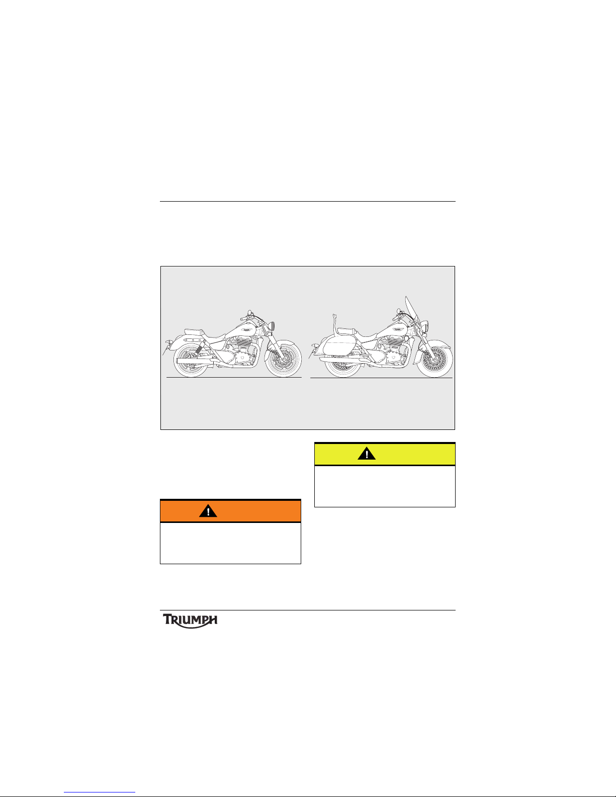
This handbook contains information on the Triumph Thunderbird Commander and the
Thunderbird LT motorcycles. Always store this Owner's Handbook with the motorcycle and
refer to it for information whenever necessary.
Warnings, Cautions and
Notes
Throughout this Owner's Handbook
particularly important information is
presented in the following form:
Note:
• This note symbol indicates points of
particular interest for more efficient
and convenient operation.
Warning
This warning symbol identifies special
instructions or procedures, which if not
correctly followed could result in personal
injury, or loss of life.
Caution
This caution symbol identifies special
instructions or procedures, which, if not
strictly observed, could result in damage to,
or destruction of, equipment.
Page 2
2
Foreword
Warning Labels
At certain areas of the
motorcycle, the symbol (left)
can be seen. The symbol
means 'CAUTION: REFER TO
THE HANDBOOK' and will
be followed by a pictorial
representation of the subject
concerned.
Never attempt to ride the motorcycle or
make any adjustments without reference to
the relevant instructions contained in this
handbook.
See pages 10 to 13 for the location of all
labels bearing this symbol. Where necessary,
this symbol will also appear on the pages
containing the relevant information.
Maintenance
To ensure a long, safe and trouble free life for
your motorcycle, maintenance should only be
carried out by an authorised Triumph dealer.
Only an authorised Triumph dealer will have
the necessary knowledge, equipment and
skills to maintain your Triumph motorcycle
correctly.
To locate your nearest Triumph dealer, visit
the Triumph web site at www.triumph.co.uk
or telephone the authorised distributor in
your country. Their address is given in the
service record book that accompanies this
handbook.
Noise Control System
Tampering With the Noise Control System is
Prohibited.
Owners are warned that the law may prohibit:
a) The removal or rendering inoperative by
any person other than for purposes of
maintenance, repair or replacement, of
any device or element of design
incorporated into any new vehicle for the
purpose of noise control prior to its sale
or delivery to the ultimate purchaser or
while it is in use and,
b) the use of the vehicle after such device or
element of design has been removed or
rendered inoperative by any person.
Immobiliser and Tyre
Pressure Monitoring System
This device complies with part 15 of the FCC
Rules.
Operation is subject to the following two
conditions:
• This device may not cause harmful
interference
• This device must accept any interference
received, including interference that may
cause undesired operation.
Changes or modifications to the device could
void the user's authority to operate the
equipment.
Page 3
3
Foreword
Tyres
With reference to the Pneumatic Tyres and
Tubes for Automotive Vehicles (Quality
Control) Order, 2009, Cl. No. 3 (c), it is
declared by M/s. Triumph Motorcycles Ltd.
that the tyres fitted on this motorcycle meet
the requirements of IS 15627: 2005 and
comply with the requirements under Central
Motor Vehicle Rules (CMVR), 1989.
Owner's Handbook
Thank you for choosing a Triumph
motorcycle. This motorcycle is the product of
Triumph's use of proven engineering,
exhaustive testing, and continuous striving for
superior reliability, safety and performance.
Please read this Owner's Handbook before
riding in order to become thoroughly familiar
with the correct operation of your motorcycle's
controls, its features, capabilities and limitations.
This handbook includes safe riding tips, but
does not contain all the techniques and skills
necessary to ride a motorcycle safely.
Triumph strongly recommends that all riders
undertake the necessary training to ensure
safe operation of this motorcycle.
This handbook is also available from your
local dealer in:
•Dutch
•French
•German
•Italian
• Japanese
• Portuguese
• Spanish
•Swedish.
Note:
• The fitting of some accessory kits
requires removal of the original pillion
seat, which houses the handbook. In
these circumstances, ensure the
Owner's Handbook is removed from
the pillion seat and carried with the
motorcycle at all times.
Warning
This Owner's Handbook, and all other
instructions that are supplied with your
motorcycle, should be considered a
permanent part of your motorcycle and
should remain with it even if your
motorcycle is subsequently sold.
All riders must read this Owner's
Handbook and all other instructions which
are supplied with your motorcycle, before
riding, in order to become thoroughly
familiar with the correct operation of your
motorcycle's controls, its features,
capabilities and limitations. Do not lend
your motorcycle to others as riding when
not familiar with your motorcycle's controls,
features, capabilities and limitations can
lead to an accident.
Page 4

4
Foreword
Tal k to Tr iu m ph
Our relationship with you does not end with
the purchase of your Triumph. Your feedback
on the buying and ownership experience is
very important in helping us develop our
products and services for you. Please help us
by ensuring your dealership has your Email
address and registers this with us. You will
then receive an online customer satisfaction
survey invitation to your Email address where
you can give us this feedback.
Your Triumph team.
Information
The information contained in this publication
is based on the latest information available at
the time of printing. Triumph reserves the
right to make changes at any time without
prior notice, or obligation.
Not to be reproduced wholly or in part
without the written permission of Triumph
Motorcycles Limited.
© Copyright 10.2013 Triumph Motorcycles
Limited, Hinckley, Leicestershire, England.
Publication part number 3852561 issue 1.
Table of Contents
This handbook contains a number of different sections. The table of contents below will help
you find the beginning of each section where, in the case of the major sections, a further table
of contents will help you find the specific subject required.
Foreword. . . . . . . . . . . . . . . . . . . . . . . . . . . . . . . . . . . . . . . . . . . . . . . . . . . . . . . . . . . . . . . . . . . . 1
Warning Labels. . . . . . . . . . . . . . . . . . . . . . . . . . . . . . . . . . . . . . . . . . . . . . . . . . . . . . . . . . . . . . 10
Parts Identification. . . . . . . . . . . . . . . . . . . . . . . . . . . . . . . . . . . . . . . . . . . . . . . . . . . . . . . . . . . . 14
Serial Numbers. . . . . . . . . . . . . . . . . . . . . . . . . . . . . . . . . . . . . . . . . . . . . . . . . . . . . . . . . . . . . . 19
General Information . . . . . . . . . . . . . . . . . . . . . . . . . . . . . . . . . . . . . . . . . . . . . . . . . . . . . . . . . . 21
How to Ride the Motorcycle . . . . . . . . . . . . . . . . . . . . . . . . . . . . . . . . . . . . . . . . . . . . . . . . . . . 49
Accessories, Loading and Passengers . . . . . . . . . . . . . . . . . . . . . . . . . . . . . . . . . . . . . . . . . . . . 61
Maintenance and Adjustment . . . . . . . . . . . . . . . . . . . . . . . . . . . . . . . . . . . . . . . . . . . . . . . . . . 65
Storage . . . . . . . . . . . . . . . . . . . . . . . . . . . . . . . . . . . . . . . . . . . . . . . . . . . . . . . . . . . . . . . . . . . 117
Specifications . . . . . . . . . . . . . . . . . . . . . . . . . . . . . . . . . . . . . . . . . . . . . . . . . . . . . . . . . . . . . . 119
Page 5

5
Foreword - Safety First
FOREWORD - SAFETY FIRST
The Motorcycle Fuel and Exhaust Fumes
Warning
This motorcycle is designed for on-road
use only. It is not suitable for off-road use.
Off-road operation could lead to loss of
control of the motorcycle resulting in an
accident causing injury or loss of life.
Warning
This motorcycle is not designed to tow a
trailer or be fitted with a sidecar. Fitting a
sidecar and/or a trailer may result in loss of
control and an accident.
Warning
This motorcycle is designed for use as a
two-wheeled vehicle capable of carrying a
rider on his/her own, or a rider and one
passenger (subject to a passenger seat
being fitted).
The total weight of the rider, and any
passenger, accessories and luggage must
not exceed the maximum load limit of:
• 220 kg for Thunderbird LT.
• 232 kg for Thunderbird Commander.
Warning
PETROL IS HIGHLY FLAMMABLE:
Always turn off the engine when refuelling.
Do not refuel or open the fuel filler cap
while smoking or in the vicinity of any
open (naked) flame.
Take care not to spill any petrol on the
engine, exhaust pipes or silencers when
refuelling.
If petrol is swallowed, inhaled or allowed to
get into the eyes, seek immediate medical
attention.
Spillage on the skin should be immediately
washed off with soap and water and
clothing contaminated with petrol should
immediately be removed.
Burns and other serious skin conditions
may result from contact with petrol.
Warning
Never start your engine or let it run for any
length of time in a closed area. The
exhaust fumes are poisonous and may
cause loss of consciousness and death
within a short time. Always operate your
motorcycle in the open-air or in an area
with adequate ventilation.
Page 6
6
Foreword - Safety First
Helmet and Clothing Parking
Warning
When riding the motorcycle, both rider
and passenger must always wear a
motorcycle helmet, eye protection, gloves,
boots, trousers (close fitting around the
knee and ankle) and a brightly coloured
jacket. Brightly coloured clothing will
considerably increase a rider's (or
passenger's) visibility to other operators of
road vehicles. Although full protection is
not possible, wearing correct protective
clothing can reduce the risk of injury when
riding.
Warning
A helmet is one of the most important
pieces of riding gear as it offers protection
against head injuries. You and your
passenger's helmet should be carefully
chosen and should fit you or your
passenger's head comfortably and
securely. A brightly coloured helmet will
increase a rider's (or passenger's) visibility
to other operators of road vehicles.
An open face helmet offers some
protection in an accident though a full face
helmet will offer more.
Always wear a visor or approved goggles
to help vision and to protect your eyes.
cbma
Warning
Always turn off the engine and remove the
ignition key before leaving the motorcycle
unattended. By removing the key, the risk
of use of the motorcycle by unauthorised
or untrained persons is reduced.
When parking the motorcycle, always
remember the following:
Engage first gear to help prevent the
motorcycle from rolling off the stand.
The engine and exhaust system will be hot
after riding. DO NOT park where
pedestrians, animals and/or children are
likely to touch the motorcycle.
Do not park on soft ground or on a steeply
inclined surface. Parking under these
conditions may cause the motorcycle to fall
over.
For further details, please refer to the 'How
to Ride the Motorcycle' section of this
Owner's Handbook.
Page 7
7
Foreword - Safety First
Parts and Accessories
Triumph does not accept any liability
whatsoever for defects caused by the fitting
of non-approved parts, accessories or
conversions or the fitting of any approved
parts, accessories or conversions by
non-approved personnel.
Maintenance/Equipment
Warning
Owners should be aware that the only
approved parts, accessories and
conversions for any Triumph motorcycle
are those which carry official Triumph
approval and are fitted to the motorcycle
by an authorised dealer.
In particular, it is extremely hazardous to fit
or replace parts or accessories whose fitting
requires the dismantling of, or addition to,
either the electrical or fuel systems and any
such modification could cause a safety
hazard.
The fitting of any non-approved parts,
accessories or conversions may adversely
affect the handling, stability or other aspect
of the motorcycle operation that may result
in loss of motorcycle control and an accident.
Warning
Consult your authorised Triumph dealer
whenever there is doubt as to the correct or
safe operation of this Triumph motorcycle.
Remember that continued operation of an
incorrectly performing motorcycle may
aggravate a fault and may also
compromise safety.
Warning
Use of a motorcycle with bank angle
indicators worn beyond the maximum
limit will allow the motorcycle to be
banked to an unsafe angle.
Banking to an unsafe angle may cause
instability, loss of motorcycle control and
an accident.
Details of the bank angle wear limits can
be found in the maintenance and
adjustment section on page 78.
Warning
Ensure all equipment that is required by
law is installed and functioning correctly.
The removal or alteration of the
motorcycle’s lights, silencers, emission or
noise control systems can violate the law.
Incorrect or improper modification may
adversely affect the handling, stability or
other aspect of the motorcycle operation,
which may result in loss of motorcycle
control and an accident.
Warning
If the motorcycle is involved in an accident,
collision or fall, it must be taken to an
authorised Triumph dealer for inspection
and repair. Any accident can cause
damage to the motorcycle that, if not
correctly repaired, may cause a second
accident that may result in injury or death.
Page 8
8
Foreword - Safety First
Riding
Warning
Never ride the motorcycle when fatigued
or under the influence of alcohol or other
drugs.
Riding when under the influence of alcohol
or other drugs is illegal.
Riding when fatigued or under the
influence of alcohol or other drugs reduces
the rider's ability to maintain control of the
motorcycle and may lead to loss of control
and an accident.
Warning
All riders must be licenced to operate the
motorcycle. Operation of the motorcycle
without a licence is illegal and could lead to
prosecution.
Operation of the motorcycle without
formal training in the correct riding
techniques that are necessary to become
licenced is dangerous and may lead to loss
of motorcycle control and an accident.
Warning
Always ride defensively and wear the
protective equipment mentioned
elsewhere in this foreword. Remember, in
an accident, a motorcycle does not give the
same impact protection as a car.
Warning
This Triumph motorcycle should be
operated within the legal speed limits for
the particular road travelled. Operating a
motorcycle at high speeds can be
potentially dangerous since the time
available to react to given traffic situations
is greatly reduced as road speed increases.
Always reduce speed in potentially
hazardous driving conditions such as bad
weather or heavy traffic.
Warning
Continually observe and react to changes in
road surface, traffic and wind conditions. All
two-wheeled vehicles are subject to external
forces which may cause an accident. These
forces include but are not limited to:
• Wind draft from passing vehicles
• Potholes, uneven or damaged road
surfaces
• Bad weather
•Rider error.
Always operate the motorcycle at moderate
speed and away from heavy traffic until
you have become thoroughly familiar with
its handling and operating characteristics.
Never exceed the legal speed limit.
Page 9
9
Foreword - Safety First
Handlebars and Footrests
Warning
The rider must maintain control of the
vehicle by keeping hands on the
handlebars at all times.
The handling and stability of a motorcycle
will be adversely affected if the rider
removes his hands from the handlebars,
resulting in loss of motorcycle control and
an accident.
Warning
The rider and passenger must always use
the footrests provided, during operation of
the vehicle.
By using the footrests, both rider and
passenger will reduce the risk of
inadvertent contact with any motorcycle
components and will also reduce the risk of
injury from entrapment of clothing.
Warning
The bank angle indicators must not be
used as a guide to how far the motorcycle
may be safely banked. This depends on
many various conditions including, but not
limited to, road surface, tyre condition and
weather.
Banking to an unsafe angle will lead to loss
of motorcycle control and an accident.
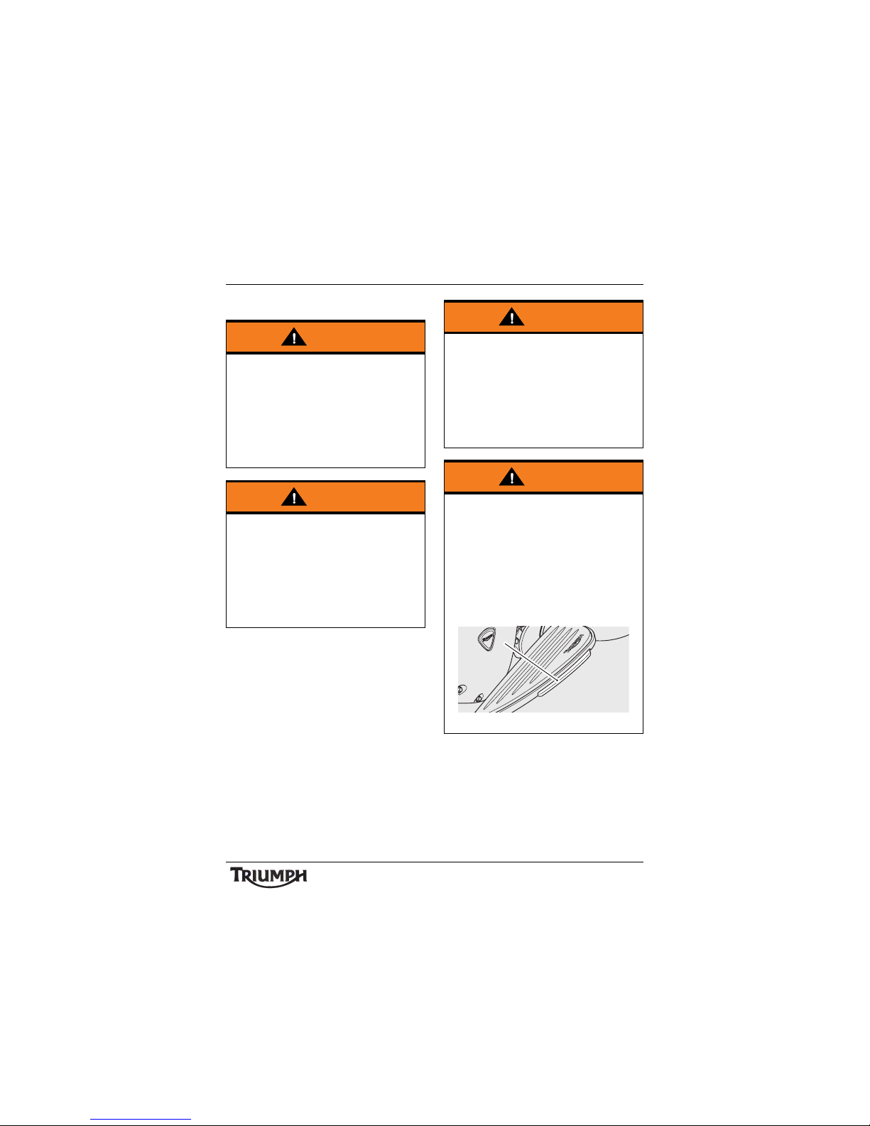
Warning
When banking and the bank angle
indicator, attached to the rider’s footboard,
makes contact with the ground, the
motorcycle is nearing its bank angle limit.
A further increase of the banking angle is
unsafe.
Banking to an unsafe angle may cause
instability, loss of motorcycle control and
an accident.
1. Bank angle indicator
1
Page 10

Warning Labels
10
WARNING LABELS
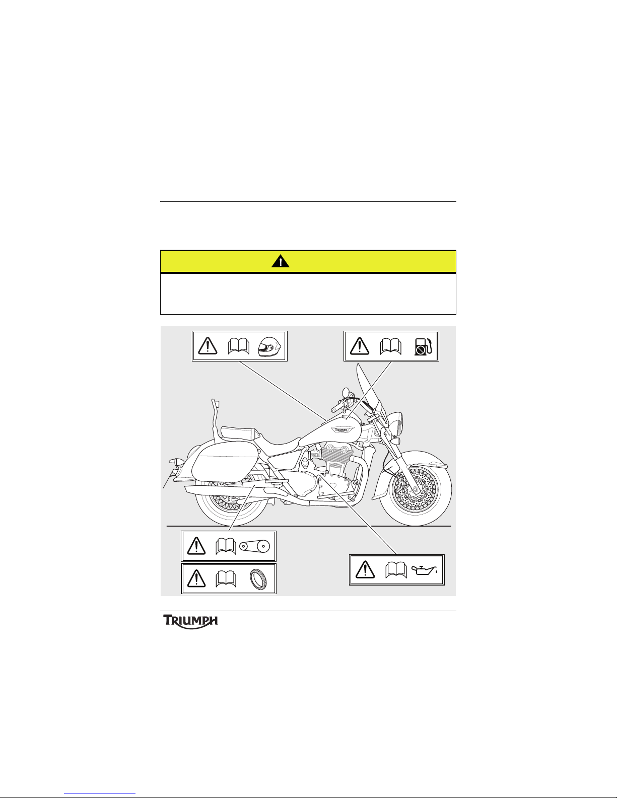
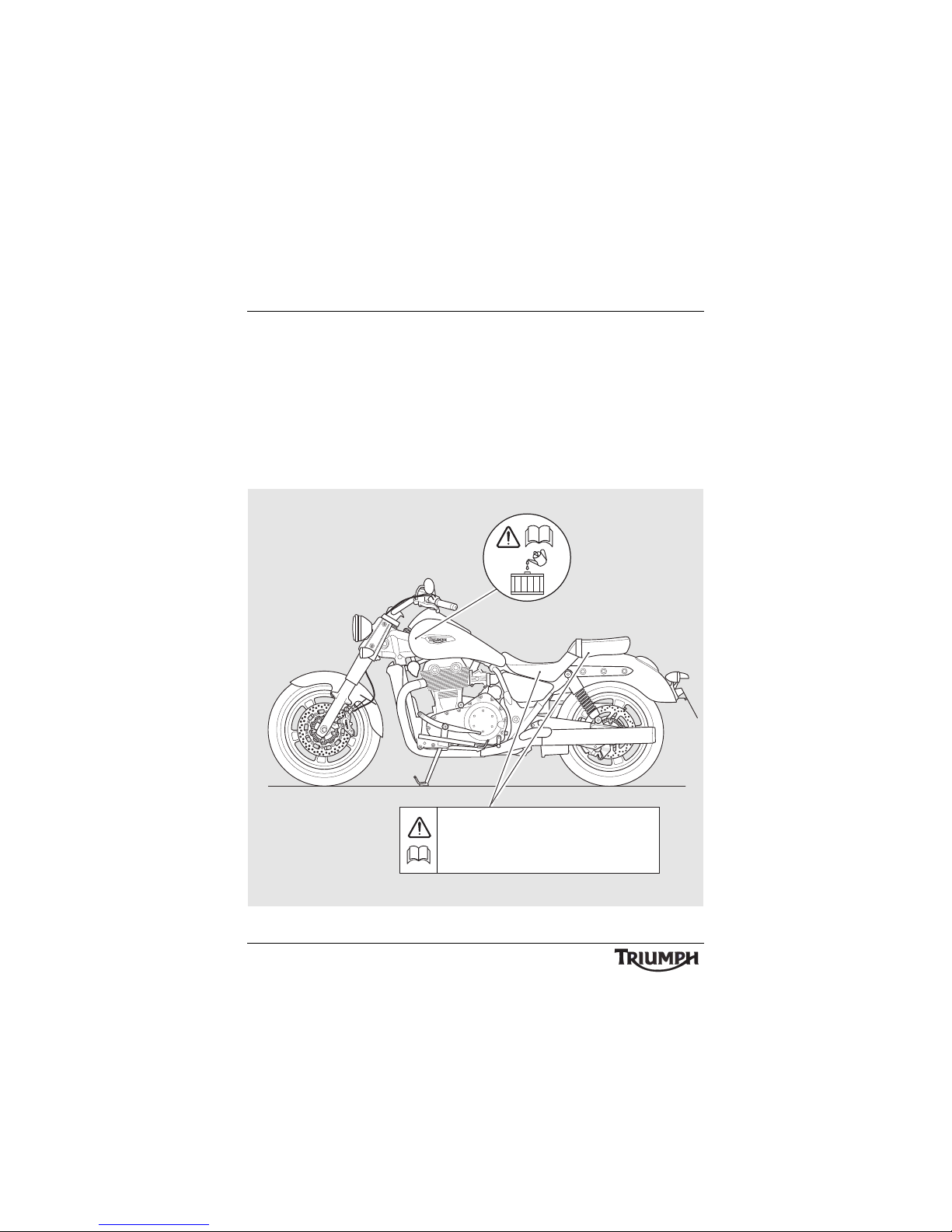
Warning Label Locations – Thunderbird LT
The labels detailed on this and the following pages draw your attention to important safety
information in this handbook. Before riding, ensure that all riders have understood and
complied with all the information to which these labels relate.
DAILY SAFETY CHECKS AND SEAT CARE
CONTRÔLES DE SÉCURIT É QUOTIDIEN ET NETT OYAGE DE LA SELLE
COMPROBACIONES DIARIAS Y EL MANTENIMIENTO DE SU ASIENTO
DAGELIJKSE VEILIGHEIDSCONTROLES EN ZADELONDERHOUD
TÄGLICHE SICHERHEITSKONT ROLLEN UND PFLEGE DES SITZES
DAGLIGA SÄKERHETSKONTROLLER OCH VÅRD AV SADEL
CONTROLLI DI SICUREZZA GIORNALIERI E PULIZIA SELLA
日常安全点検とシートのお手入れ
Coolant
(page 74)
Daily Safety
Checks
(page 48)
Windscreen
(page 113 )
Page 11
Warning Labels
11
Warning Label Locations – Thunderbird LT (continued)
Caution
All warning labels and decals, with the exception of the Running-in label, are fitted to the
motorcycle using a strong adhesive. In some cases, labels are installed prior to an application
of paint lacquer. Therefore, any attempt to remove the warning labels will cause damage to
the paintwork or bodywork.
P
b
Unleaded Fuel
(page 35)
Helmet
(page 6)
Engine Oil
(page 71 )
Tyr es
(page 96)
Drive Belt
(page 90)
Page 12
Warning Labels
12
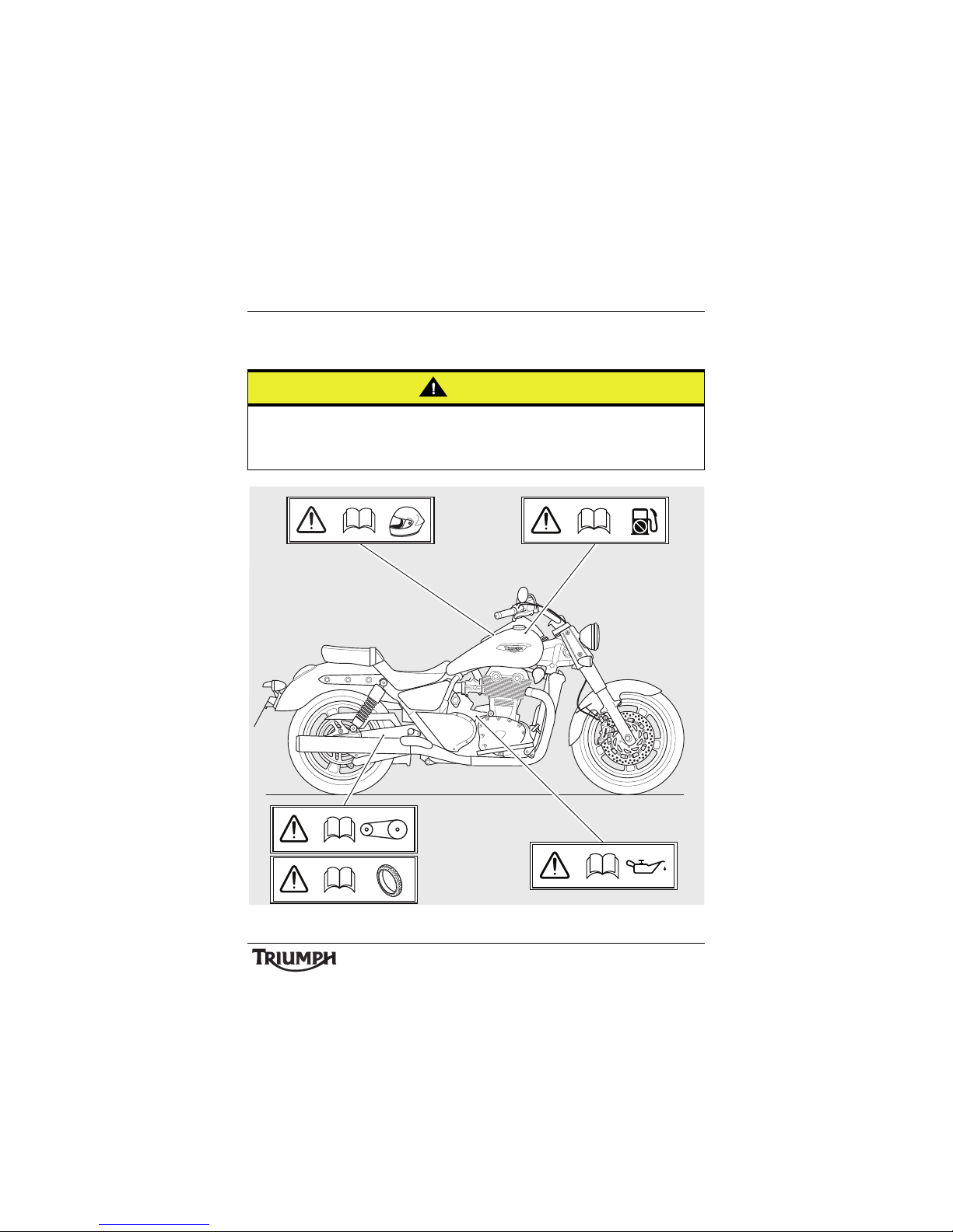
Warning Label Locations – Thunderbird Commander
The labels detailed on this and the following pages draw your attention to important safety
information in this handbook. Before riding, ensure that all riders have understood and
complied with all the information to which these labels relate.
DAILY SAFETY CHECKS AND SEAT CARE
CONTRÔLES DE SÉCURITÉ QUOTIDIEN ET NETTOY AGE DE LA SELLE
COMPROBACIONES DIARIAS Y EL MANTENIMIENTO DE SU ASIENTO
DAGELIJKSE VEILIGHEIDSCONTROLES EN ZADELONDERHOU D
TÄGLICHE SICHERHEITSKONTROLLEN UND PFLEGE DES SITZES
DAGLIGA SÄKERHETSKONTROLLER OCH VÅRD AV SADEL
CONTROLLI DI SICUREZZA GIORNALIERI E PULIZIA SELLA
日常安全点検とシートのお手入れ
Coolant
(page 74)
Daily Safety
Checks
(page 48)
Page 13
Warning Labels
13
Warning Label Locations – Thunderbird Commander
(continued)
Caution
All warning labels and decals, with the exception of the Running-in label, are fitted to the
motorcycle using a strong adhesive. In some cases, labels are installed prior to an application
of paint lacquer. Therefore, any attempt to remove the warning labels will cause damage to
the paintwork or bodywork.
P
b
Unleaded Fuel
(page 35)
Helmet
(page 6)
Engine Oil
(page 71 )
Tyr es
(page 96)
Drive Belt
(page 90)
Page 14
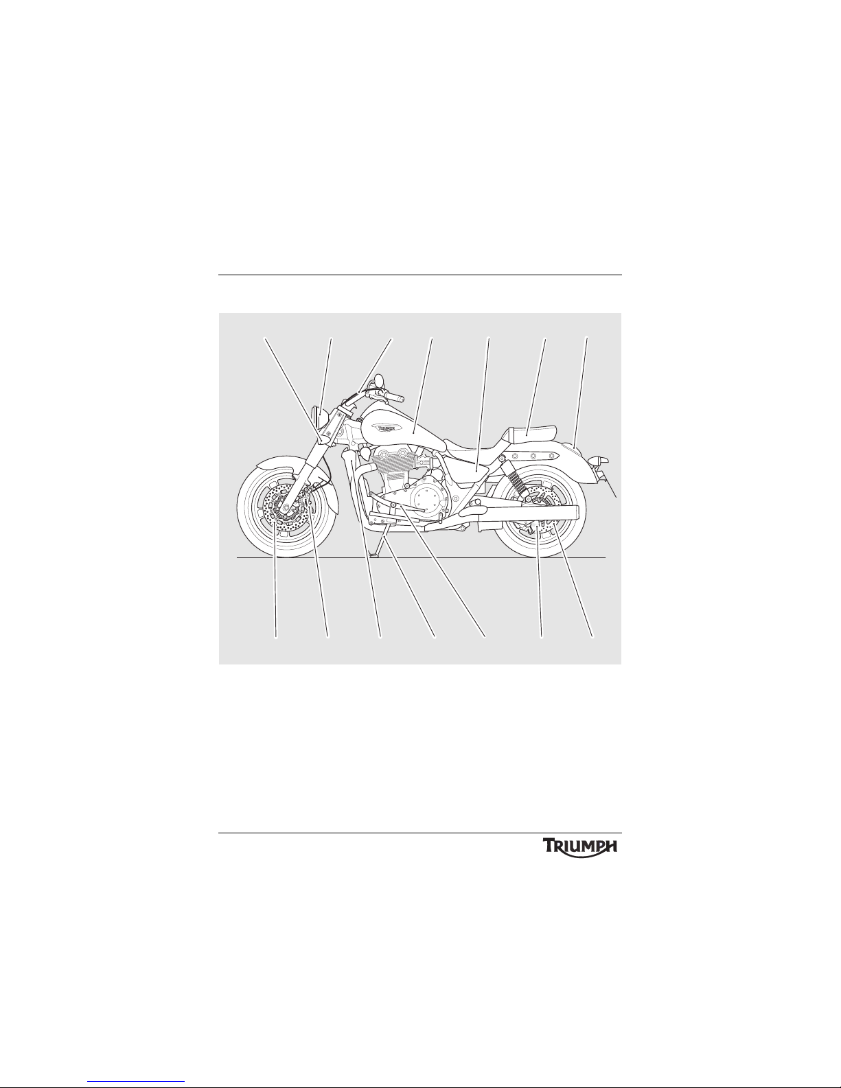
14
Parts Identification
PARTS IDENTIFICATION
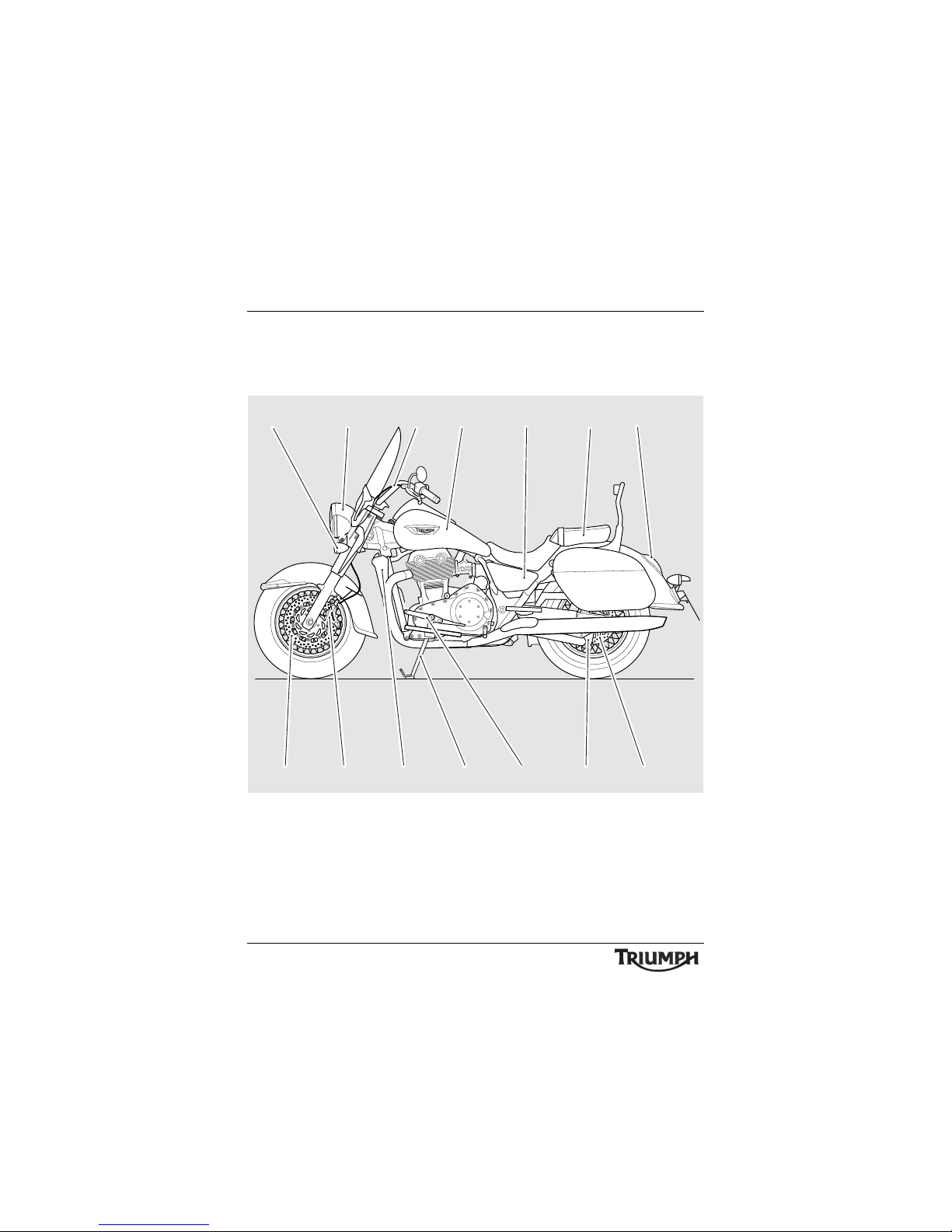
Thunderbird LT
1. Front indicator
2. Headlight
3. Clutch cable
4. Fuel tank
5. Allen key (behind side panel)
6. Handbook/C-spanner (beneath
pillion seat)
7. Brake/Rear light
8. Rear brake disc
9. Rear brake caliper
10. Gear change pedal
11. S i d e s ta nd
12 . R a d i a t o r
13. Front brake caliper
14. Front brake disc
1
2 3456
14 13
12 11 10 9 8
7
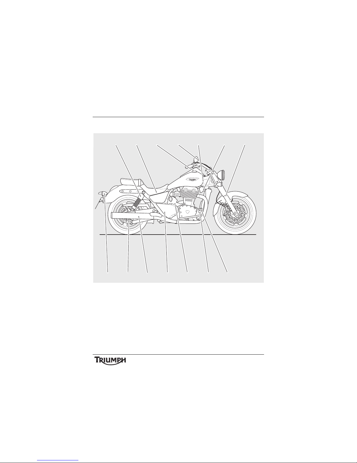
Page 15
15
Parts Identification
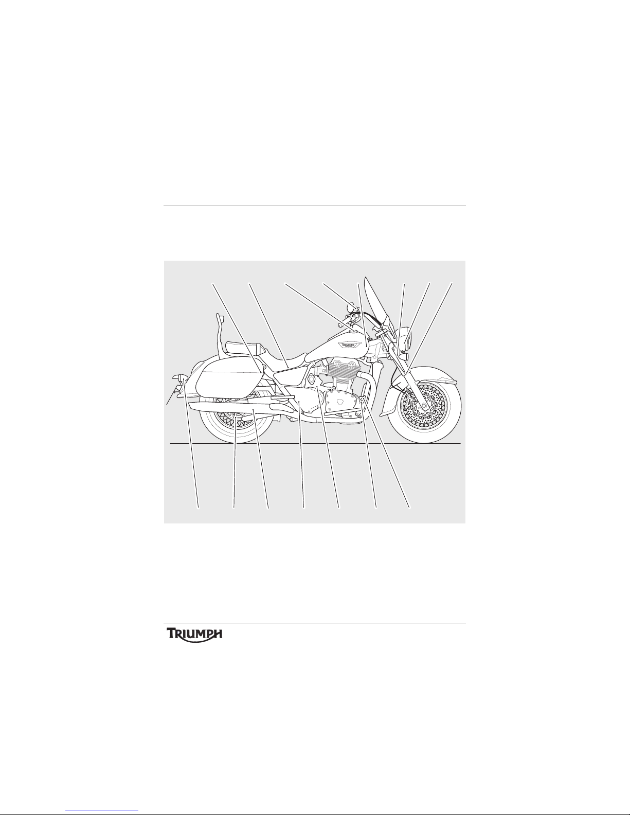
15. Rear suspension unit (behind pannier)
16. Battery (beneath seat)
17. Fuel filler cap
18. Front brake fluid reservoir
19. Coolant pressure cap (beneath fuel
tank)
20. Horn
21. Fog light
22. Front fork
23. Rear brake pedal
24. Rear brake fluid reservoir
25. Oil filler cap/Dipstick
26. Coolant expansion tank (behind
drive belt pulley cover)
27. Sile ncer
28. Drive belt pulley
29. Rear indicator
15 16 17 18 19 20 22
29 28 23
27 26 25 24
21
Page 16
16
Parts Identification
Thunderbird Commander
1. Front indicator
2. Headlight
3. Clutch cable
4. Fuel tank
5. Allen key (behind side panel)
6. Handbook/C-spanner (beneath
pillion seat)
7. Brake/Rear light
8. Rear brake disc
9. Rear brake caliper
10. Gear change pedal
11. S i d e s ta nd
12 . R a d i a t o r
13. Front brake caliper
14. Front brake disc
1
2 3456
14 13
12 11 10 9 8
7
Page 17
17
Parts Identification
15. Rear suspension unit
16. Battery (beneath seat)
17. Fuel filler cap
18. Front brake fluid reservoir
19. Coolant pressure cap (beneath fuel
tank)
20. Horn
21. Front fork
22. Rear brake pedal
23. Rear brake fluid reservoir
24. Oil filler cap/Dipstick
25. Coolant expansion tank (behind
drive belt pulley cover)
26. Silencer
27. Driv e belt pulley
28. Rear indicator
15 16 17 18 19 20 21
28 27 22
26 25 24 23
Page 18
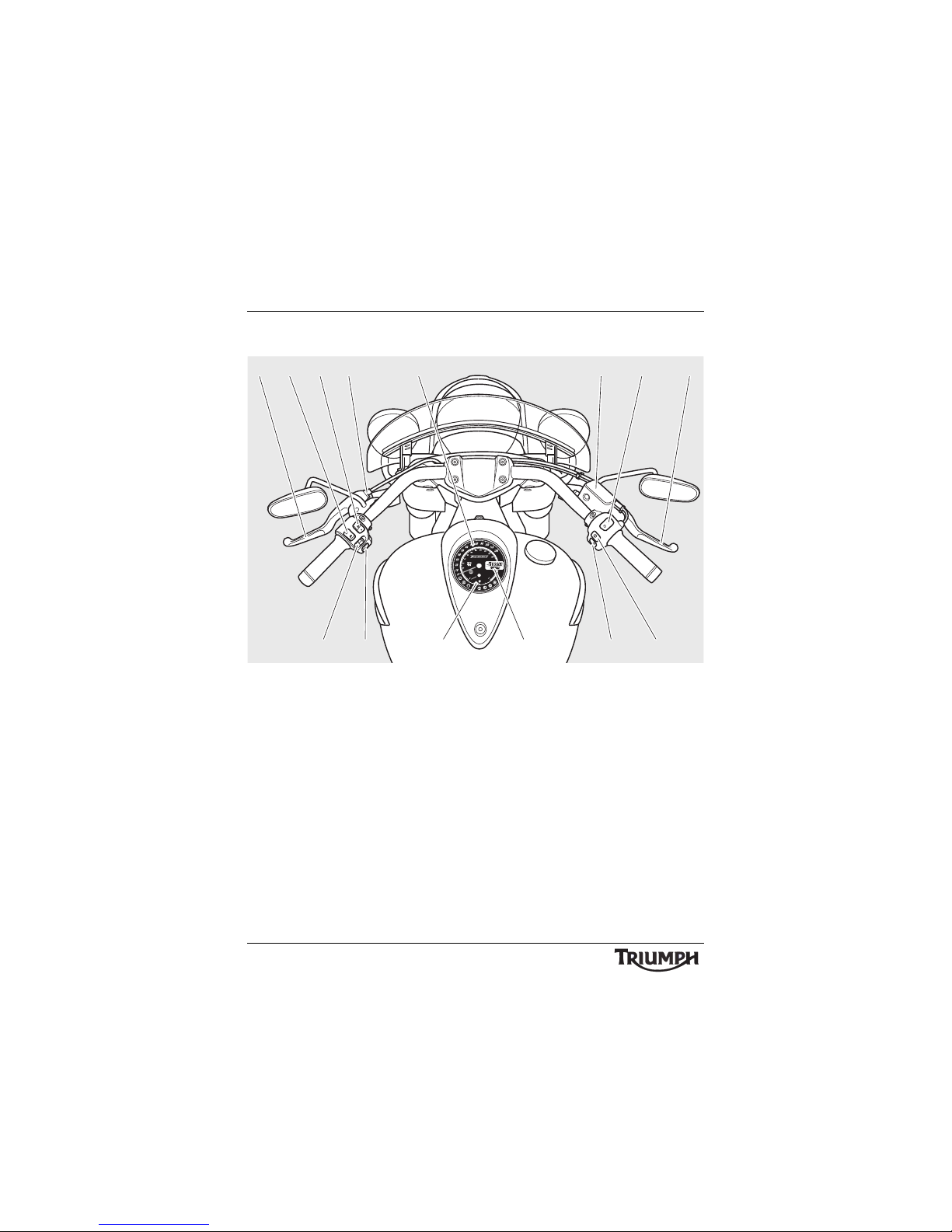
18
Parts Identification
Thunderbird LT Shown
1. C l u tc h l ev er
2. Headlight dip switch
3. Fog lamp switch
4. Clutch lever adjuster
5. Speedometer
6. Front brake fluid reservoir
7. Engine stop switch
8. Front brake lever
9. Scroll button
10. Starter button
11. Odometer
12. Fuel gauge
13. Horn button
14. Indicator switch
TRIP
1
2
1234 5
cihe
67
91011121314
8
Page 19
19
Serial Numbers
SERIAL NUMBERS
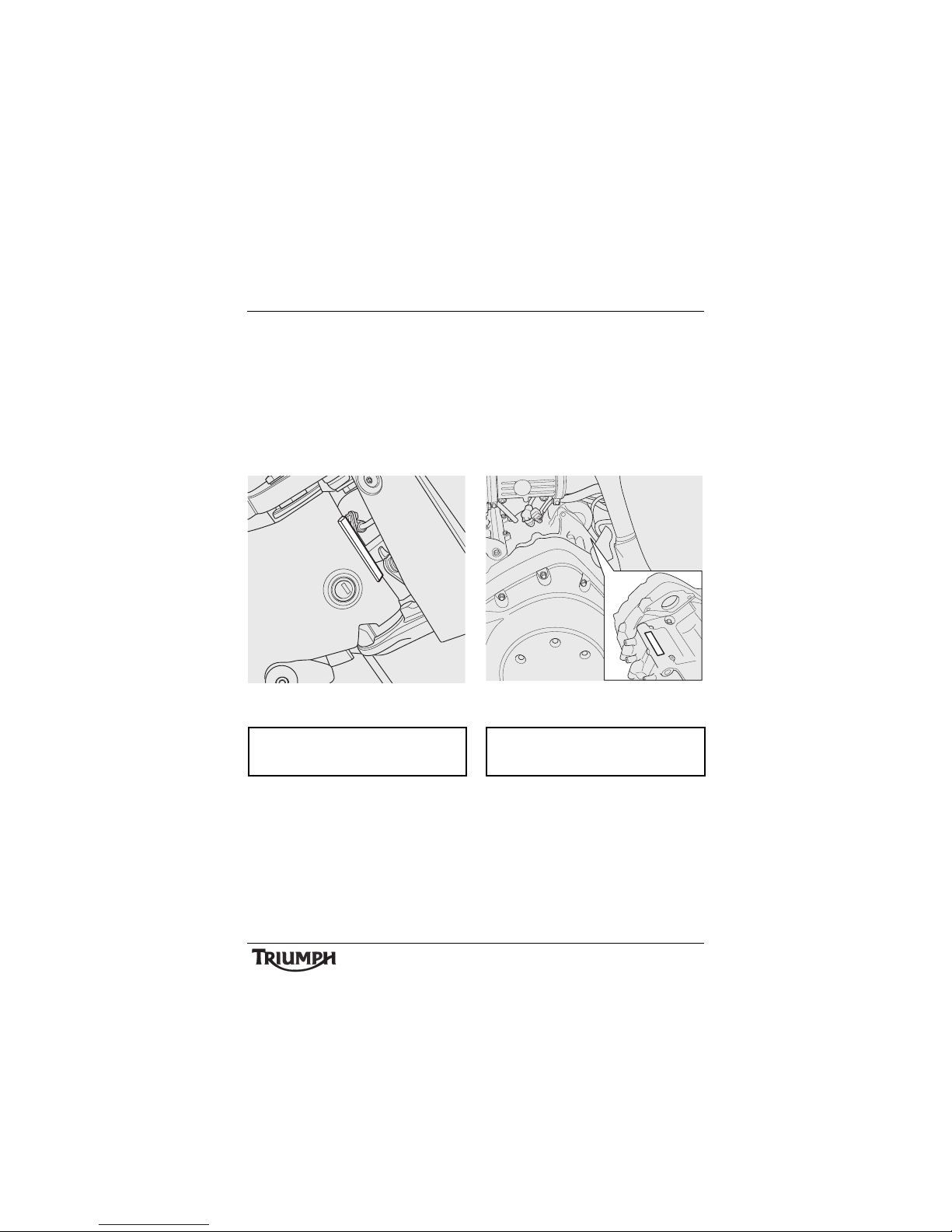
Vehicle Identification
Number (VIN)
The vehicle identification number is stamped
into the steering head area of the frame. It is
also displayed on a plate, riveted to the
frame, on the engine’s left hand cradle tube.
Record the vehicle identification number in
the space provided below.
Engine Serial Number
The engine serial number is stamped on the
upper engine crankcase, towards the rear,
and is visible from left hand side, behind the
starter motor.
Record the engine serial number in the space
provided below.
ciid
cfbw
Page 20

20
Serial Numbers
This page intentionally left blank
Page 21

General Information
21
GENERAL INFORMATION
Table of Contents
Instrument Panel Layout. . . . . . . . . . . . . . . . . . . . . . . . . . . . . . . . . . . . . . . . . . . . . . . . . . . . . . . 23
Instruments . . . . . . . . . . . . . . . . . . . . . . . . . . . . . . . . . . . . . . . . . . . . . . . . . . . . . . . . . . . . . . . . . 24
Speedometer . . . . . . . . . . . . . . . . . . . . . . . . . . . . . . . . . . . . . . . . . . . . . . . . . . . . . . . . . . . . 24
Odometer/Trip Meter/Clock/Range to Empty . . . . . . . . . . . . . . . . . . . . . . . . . . . . . . . . . . 24
Clock Adjustment . . . . . . . . . . . . . . . . . . . . . . . . . . . . . . . . . . . . . . . . . . . . . . . . . . . . . . . . 25
Range to Empty. . . . . . . . . . . . . . . . . . . . . . . . . . . . . . . . . . . . . . . . . . . . . . . . . . . . . . . . . . 25
Fuel Gauge . . . . . . . . . . . . . . . . . . . . . . . . . . . . . . . . . . . . . . . . . . . . . . . . . . . . . . . . . . . . . 26
Warning Lights . . . . . . . . . . . . . . . . . . . . . . . . . . . . . . . . . . . . . . . . . . . . . . . . . . . . . . . . . . . . . . 26
Low Oil Pressure Warning . . . . . . . . . . . . . . . . . . . . . . . . . . . . . . . . . . . . . . . . . . . . . . . . . 26
Coolant Temperature. . . . . . . . . . . . . . . . . . . . . . . . . . . . . . . . . . . . . . . . . . . . . . . . . . . . . . 26
Engine Management System Malfunction Indicator Light . . . . . . . . . . . . . . . . . . . . . . . . 27
Direction Indicators . . . . . . . . . . . . . . . . . . . . . . . . . . . . . . . . . . . . . . . . . . . . . . . . . . . . . . . 27
High Beam. . . . . . . . . . . . . . . . . . . . . . . . . . . . . . . . . . . . . . . . . . . . . . . . . . . . . . . . . . . . . . 27
Neutral . . . . . . . . . . . . . . . . . . . . . . . . . . . . . . . . . . . . . . . . . . . . . . . . . . . . . . . . . . . . . . . . . 27
Low Fuel. . . . . . . . . . . . . . . . . . . . . . . . . . . . . . . . . . . . . . . . . . . . . . . . . . . . . . . . . . . . . . . . 27
Alarm/Immobiliser Indicator Light . . . . . . . . . . . . . . . . . . . . . . . . . . . . . . . . . . . . . . . . . . . 28
ABS (Anti-Lock Brake System) Indicator Light . . . . . . . . . . . . . . . . . . . . . . . . . . . . . . . . . . 28
Ignition Key. . . . . . . . . . . . . . . . . . . . . . . . . . . . . . . . . . . . . . . . . . . . . . . . . . . . . . . . . . . . . . . . . 29
Ignition Switch . . . . . . . . . . . . . . . . . . . . . . . . . . . . . . . . . . . . . . . . . . . . . . . . . . . . . . . . . . . . . . 30
Engine Immobiliser . . . . . . . . . . . . . . . . . . . . . . . . . . . . . . . . . . . . . . . . . . . . . . . . . . . . . . . 30
Switch Location . . . . . . . . . . . . . . . . . . . . . . . . . . . . . . . . . . . . . . . . . . . . . . . . . . . . . . . . . . 30
Switch Operation. . . . . . . . . . . . . . . . . . . . . . . . . . . . . . . . . . . . . . . . . . . . . . . . . . . . . . . . . 30
Steering Lock Key. . . . . . . . . . . . . . . . . . . . . . . . . . . . . . . . . . . . . . . . . . . . . . . . . . . . . . . . . . . . 31
Steering Lock . . . . . . . . . . . . . . . . . . . . . . . . . . . . . . . . . . . . . . . . . . . . . . . . . . . . . . . . . . . . . . . 32
Right Handlebar Switches . . . . . . . . . . . . . . . . . . . . . . . . . . . . . . . . . . . . . . . . . . . . . . . . . . . . . 33
Engine Stop Switch . . . . . . . . . . . . . . . . . . . . . . . . . . . . . . . . . . . . . . . . . . . . . . . . . . . . . . . 33
Starter Button . . . . . . . . . . . . . . . . . . . . . . . . . . . . . . . . . . . . . . . . . . . . . . . . . . . . . . . . . . . 33
Scroll Button . . . . . . . . . . . . . . . . . . . . . . . . . . . . . . . . . . . . . . . . . . . . . . . . . . . . . . . . . . . . 33
Left Handlebar Switches. . . . . . . . . . . . . . . . . . . . . . . . . . . . . . . . . . . . . . . . . . . . . . . . . . . . . . . 34
Headlight Dip Switch. . . . . . . . . . . . . . . . . . . . . . . . . . . . . . . . . . . . . . . . . . . . . . . . . . . . . . 34
Direction Indicator Switch . . . . . . . . . . . . . . . . . . . . . . . . . . . . . . . . . . . . . . . . . . . . . . . . . . 35
Page 22

22
General Information
Horn Button. . . . . . . . . . . . . . . . . . . . . . . . . . . . . . . . . . . . . . . . . . . . . . . . . . . . . . . . . . . . . 35
Fog Light Switch . . . . . . . . . . . . . . . . . . . . . . . . . . . . . . . . . . . . . . . . . . . . . . . . . . . . . . . . . 35
Fuel Requirement/Refuelling . . . . . . . . . . . . . . . . . . . . . . . . . . . . . . . . . . . . . . . . . . . . . . . . . . . 35
Fuel Grade . . . . . . . . . . . . . . . . . . . . . . . . . . . . . . . . . . . . . . . . . . . . . . . . . . . . . . . . . . . . . . 35
Fuel Tank Cap . . . . . . . . . . . . . . . . . . . . . . . . . . . . . . . . . . . . . . . . . . . . . . . . . . . . . . . . . . . . . . . 36
Filling the Fuel Tank . . . . . . . . . . . . . . . . . . . . . . . . . . . . . . . . . . . . . . . . . . . . . . . . . . . . . . . . . . 37
Side Stand. . . . . . . . . . . . . . . . . . . . . . . . . . . . . . . . . . . . . . . . . . . . . . . . . . . . . . . . . . . . . . . . . . 38
Side Panels . . . . . . . . . . . . . . . . . . . . . . . . . . . . . . . . . . . . . . . . . . . . . . . . . . . . . . . . . . . . . . . . . 38
Tool Kit and Handbook . . . . . . . . . . . . . . . . . . . . . . . . . . . . . . . . . . . . . . . . . . . . . . . . . . . . . . . 39
Seats . . . . . . . . . . . . . . . . . . . . . . . . . . . . . . . . . . . . . . . . . . . . . . . . . . . . . . . . . . . . . . . . . . . . . . 40
Seat Care . . . . . . . . . . . . . . . . . . . . . . . . . . . . . . . . . . . . . . . . . . . . . . . . . . . . . . . . . . . . . . . 40
Pillion Seat Removal . . . . . . . . . . . . . . . . . . . . . . . . . . . . . . . . . . . . . . . . . . . . . . . . . . . . . . 40
Rider Seat Removal . . . . . . . . . . . . . . . . . . . . . . . . . . . . . . . . . . . . . . . . . . . . . . . . . . . . . . . 41
Windscreen (if fitted) . . . . . . . . . . . . . . . . . . . . . . . . . . . . . . . . . . . . . . . . . . . . . . . . . . . . . . . . . 42
To Remove the Windscreen . . . . . . . . . . . . . . . . . . . . . . . . . . . . . . . . . . . . . . . . . . . . . . . . 42
To Install the Windscreen . . . . . . . . . . . . . . . . . . . . . . . . . . . . . . . . . . . . . . . . . . . . . . . . . . 43
Panniers (if fitted) . . . . . . . . . . . . . . . . . . . . . . . . . . . . . . . . . . . . . . . . . . . . . . . . . . . . . . . . . . . . 44
To Remove the Panniers . . . . . . . . . . . . . . . . . . . . . . . . . . . . . . . . . . . . . . . . . . . . . . . . . . . 44
To Install the Panniers . . . . . . . . . . . . . . . . . . . . . . . . . . . . . . . . . . . . . . . . . . . . . . . . . . . . . 45
Running-In . . . . . . . . . . . . . . . . . . . . . . . . . . . . . . . . . . . . . . . . . . . . . . . . . . . . . . . . . . . . . . . . . 47
Safe Operation . . . . . . . . . . . . . . . . . . . . . . . . . . . . . . . . . . . . . . . . . . . . . . . . . . . . . . . . . . . . . . 48
Daily Safety Checks . . . . . . . . . . . . . . . . . . . . . . . . . . . . . . . . . . . . . . . . . . . . . . . . . . . . . . . 48
Page 23
23
General Information
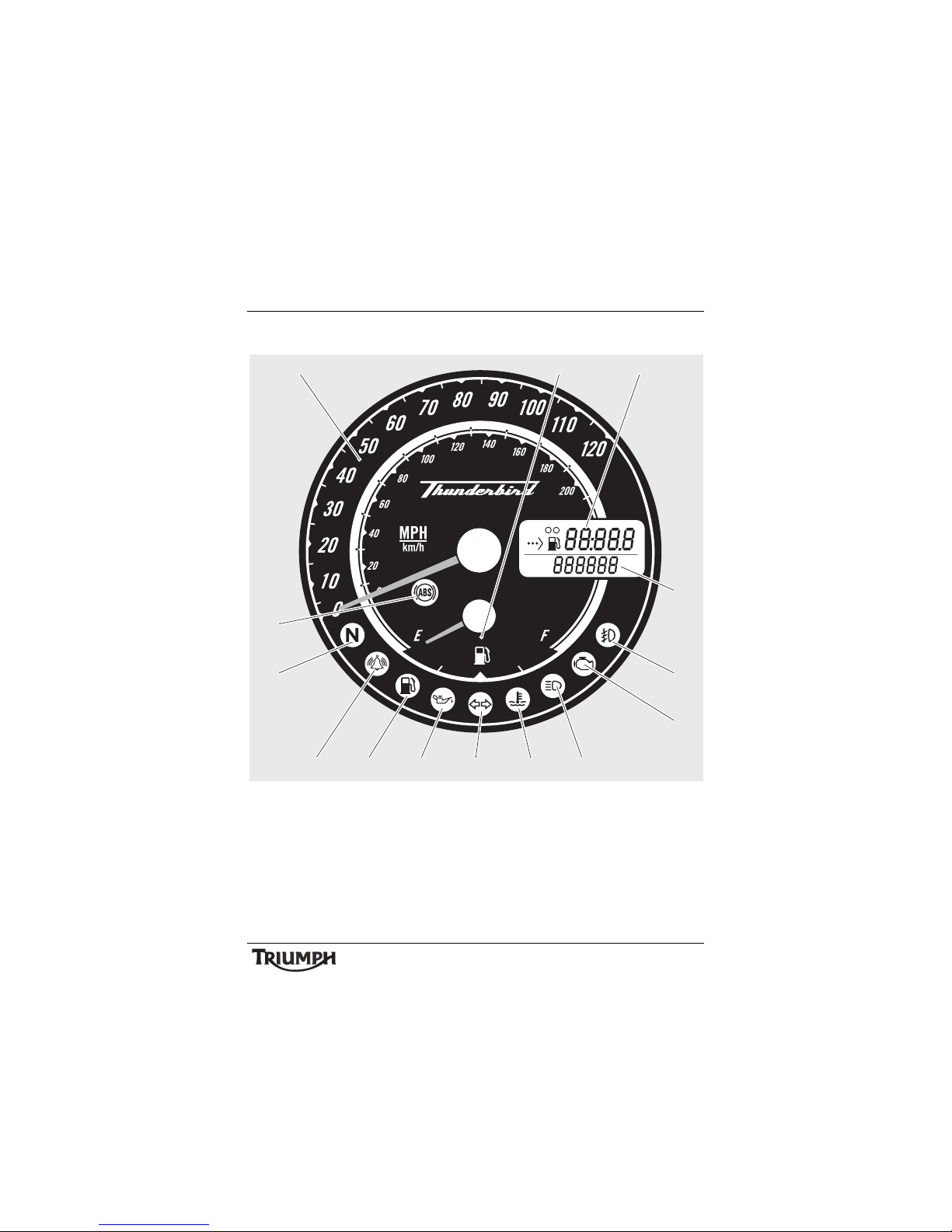
Instrument Panel Layout
1. Speedometer
2. Fuel gauge
3. Range to empty/Trip meter/Clock
4. Odometer
5. Fog light indicator light
6. Engine management malfunction
indicator light
7. High beam indicator light
8. High coolant temperature warning
light
9. Direction indicator light
10. Low oil pressure warning light
11. Low fuel level indicator light
12. Alarm/Immobiliser status indicator
light (alarm is an accessory fit)
13. Neutral indicator light
14. ABS warning light
TRIP
1
2
1 2 3
4
513
14
6
7
89101112
Page 24
24
General Information
Instruments
Speedometer
The speedometer indicates the road speed of
the motorcycle.
Odometer/Trip Meter/Clock/Range
to Empty
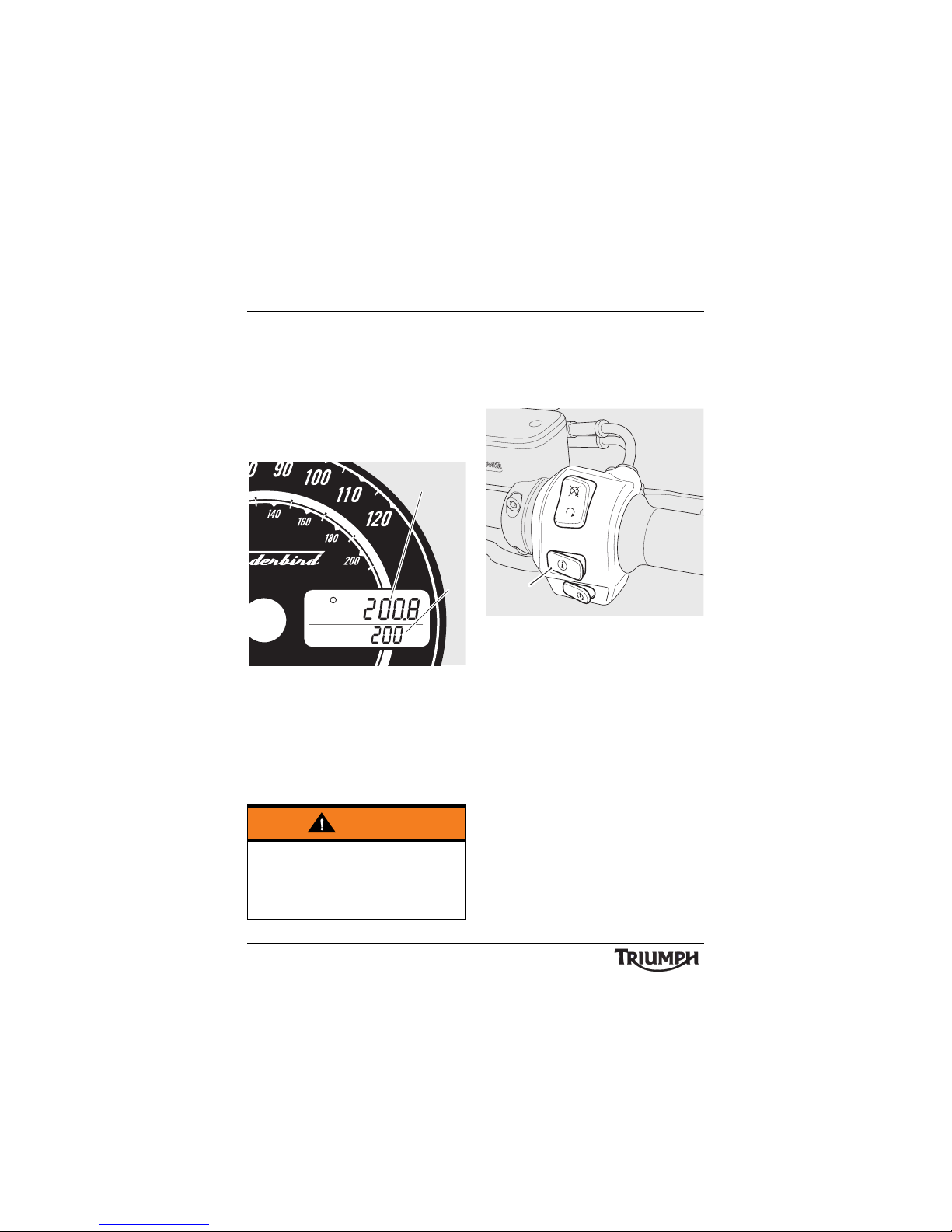
1. Trip meter display (trip 1 shown)
2. Odometer display
The odometer shows the total distance that
the motorcycle has travelled.
There are two trip meters. Either trip meter
shows the distance that the motorcycle has
travelled since the meter on display was last
reset to zero.
To switch between the trip meter, clock and
range to empty display modes, press and
release the scroll button (see below), located
on the right hand handlebar switch housing,
until the desired display is visible.
1. Scroll button
The display will scroll through in the order:
• Trip meter 1
• Trip meter 2
•Clock
• Range to empty.
Tri p Met e r Re s et
To reset either of the trip meters, select and
display the trip meter to be zeroed. Then
press and hold the scroll button for
4 seconds. After 4 seconds, the trip meter on
display will reset to zero.
Warning
Do not attempt to switch between
odometer and trip meter display modes or
reset the trip meter with the motorcycle in
motion as this may lead to loss of
motorcycle control and an accident.
TRIP
1
1
2
cfcc
1
Page 25
25
General Information
Clock Adjustment
To reset the clock, select the clock display.
Then press and hold the scroll button for
4 seconds, the clock’s hour display will start
to flash; release the scroll button.
To reset the hour display, ensure the hour
display is still flashing then press and release
the scroll button to change the setting. Each
individual button press will change the setting
by one digit. If the button is held, the display
will continuously scroll through in single digit
increments.
When the correct hour display is shown,
release the scroll button for 4 seconds. The
minutes display will begin to flash. The
minutes display is adjusted in the same way
as for the hour display.
Once both hours and minutes are correctly
set, release the scroll button for 4 seconds
and the display will cease to flash.
Range to Empty
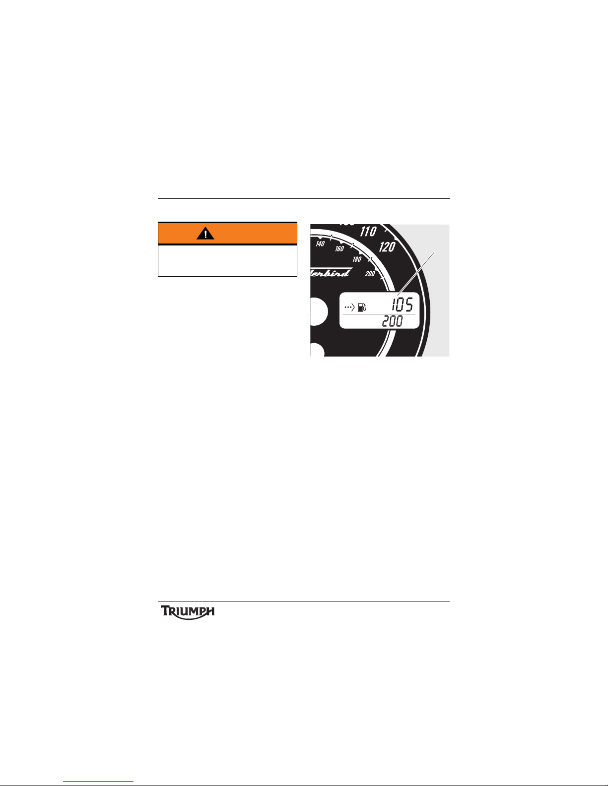
1. Range to empty
This is an indication of the predicted distance
that can be travelled on the remaining fuel in
the tank.
Warning
Do not attempt to adjust the clock with the
motorcycle in motion as this may lead to
loss of motorcycle control and an accident.
TRIP
1
2
1
Page 26
26
General Information
Fuel Gauge
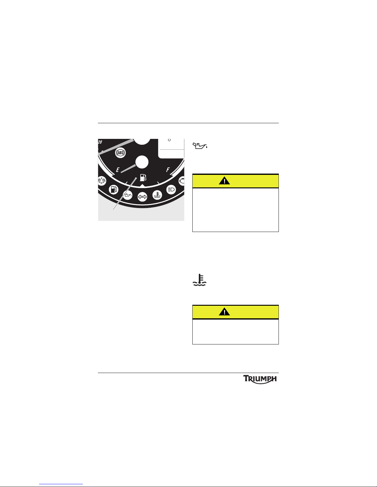
1. F u e l g au ge
The fuel gauge indicates the amount of fuel
in the tank.
When there are approximately 4.0 litres of
fuel remaining in the tank, the low fuel
warning light will illuminate and the trip
meter will switch to 'Range to Empty' display
(see page 25).
Note:
• After refuelling, the fuel gauge and
range to empty information will be
updated only while riding the
motorcycle. Depending on the riding
style, updating could take up to five
minutes.
Warning Lights
Low Oil Pressure Warning
With the engine running, if the
engine oil pressure becomes dangerously
low, the low oil pressure warning light will
illuminate.
Note:
• The low oil pressure warning light
will illuminate if the ignition is
switched on without running the
engine.
Coolant Temperature
If the coolant temperature
becomes too high, the high
coolant temperature warning light will
illuminate.
TRIP
1
2
1
Caution
Stop the engine immediately if the low oil
pressure warning light illuminates. Do not
restart the engine until the fault has been
rectified.
Severe engine damage will result from
running the engine when the low oil
pressure warning light is illuminated.
Caution
Do not continue to run the engine if the
high coolant temperature warning light is
illuminated as severe engine damage may
result.
Page 27

27
General Information
Engine Management
System Malfunction
Indicator Light
The malfunction indicator light for the engine
management system illuminates when the
ignition is switched on (to indicate that it is
working) but should not become illuminated
when the engine is running.
If the malfunction indicator light becomes
illuminated when the engine is running, this
indicates that a fault has occurred in one or
more of the systems controlled by the engine
management system. In such circumstances,
the engine management system will switch to
'limp-home' mode so that the journey may
be completed, if the fault is not so severe that
the engine will not run.
Note:
• If the malfunction indicator light
flashes when the ignition is switched
on contact an authorised Triumph
dealer as soon as possible to have
the situation rectified. In these
circumstances the engine will not
start.
Direction Indicators
When the indicator switch is
turned to left or right, the indicator warning
light will flash on and off at the same speed
as the direction indicators.
High Beam
When the ignition is switched on
and the headlight dip switch is set to
'high beam', the high beam warning light will
illuminate.
Neutral
The neutral warning light
indicates when the transmission is in neutral
(no gear selected). The warning light will
illuminate when the transmission is in neutral
with the ignition switch in the ON position.
Low Fuel
The low fuel indicator will
illuminate when there are
approximately 4.0 litres of fuel remaining in
the tank. When the low fuel indicator
illuminates, the odometer/trip meter/clock/
range to empty display will automatically
change to show the range to empty
information. To change back to the original
display, press the scroll button repeatedly
until the desired display is visible.
Warning
Reduce speed and do not continue to ride
for longer than is necessary with the
malfunction indicator light illuminated. The
fault may adversely affect engine
performance, exhaust emissions and fuel
consumption. Reduced engine
performance could cause a dangerous
riding condition, leading to loss of control
and an accident. Contact an authorised
Triumph dealer as soon as possible to have
the fault checked and rectified.
Page 28
28
General Information
Alarm/Immobiliser
Indicator Light
This Triumph model is fitted with
an engine immobiliser which is activated
when the ignition switch is turned to the OFF
position. If the motorcycle is fitted with a
genuine Triumph accessory alarm, the
immobiliser will operate as normal but the
alarm/immobiliser light will operate as
described below.
With Alarm Fitted
The alarm/immobiliser light will only
illuminate when the conditions described in
the genuine Triumph accessory alarm
instructions are met.
Without Alarm Fitted
When the ignition switch is turned to the
OFF position, the alarm/immobiliser light will
flash on and off for 24 hours to show that the
engine immobiliser is on. When the ignition
switch is turned to the ON position the
immobiliser and the indicator light will be off.
If the indicator light remains on it indicates
that the immobiliser has a malfunction that
requires investigation. Contact an authorised
Triumph dealer as soon as possible to have
the fault checked and rectified.
ABS (Anti-Lock Brake
System) Indicator Light
The ABS indicator light illuminates
to show that the ABS function is not available.
Illumination is normal after engine start-up,
and until the motorcycle first reaches a speed
exceeding 6 mph (10 km/h). Unless there is
a fault, it should not illuminate again until the
engine is restarted.
If the indicator light becomes illuminated at
any other time while riding it indicates that
the ABS has a malfunction that requires
investigation.
Warning
If the ABS is not functioning, the brake
system will continue to function as a
non-ABS braking system. Do not continue
to ride for longer than is necessary with the
indicator light illuminated. Contact an
authorised Triumph dealer as soon as
possible to have the fault checked and
rectified. In this situation braking too hard
will cause the wheels to lock resulting in
loss of motorcycle control and an accident.
Page 29

29
General Information
Ignition Key
1. Key number tag
The ignition key operates the ignition switch
only. A different key operates the steering
lock.
When the motorcycle is delivered from the
factory, two ignition keys are supplied
together with a small tag bearing the key
number. Make a note of the key number and
store the spare key and key number tag in a
safe place away from the motorcycle.
A transponder is fitted within the ignition
keys to turn off the engine immobiliser. To
ensure the immobiliser functions correctly,
always have only one of the ignition keys
near the ignition switch. Having two ignition
keys near the switch may interrupt the signal
between the transponder and the engine
immobiliser. In this situation the engine
immobiliser will remain active until one of the
ignition keys is removed.
Always get replacement keys from your
authorised Triumph dealer. Replacement keys
must be 'paired' with the motorcycle’s
immobiliser by your authorised Triumph
dealer.
Caution
The ignition and steering lock keys are
different.
However, on some models the ignition and
steering lock keys will fit either lock, but
the keys will only operate their respective
locks.
Do not use the ignition key in the steering
lock, or the steering lock key in the ignition
switch as doing so may damage or break
the key or the steering lock/ignition switch.
ceom_2
1
Caution
Do not store the spare key or key blade
with the motorcycle as this will reduce all
aspects of security.
Page 30
30
General Information
Ignition Switch
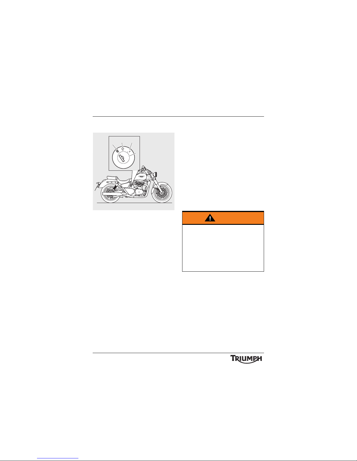
1. Ignition Switch lock
2. OFF position
3. ON position
4. PARK position
Engine Immobiliser
The ignition switch housing acts as the
antenna for the engine immobiliser.
When the ignition switch is turned to the OFF
position and the ignition key is removed, the
engine immobiliser is on (see page 28). The
engine immobiliser is turned off when the
ignition key is in the ignition switch and it is
turned to the ON position.
Switch Location
The ignition switch is located in line with the
rear edge of the fuel tank, on the right hand
side of the motorcycle.
Switch Operation
This is a three position, key operated switch.
The key can be removed from the switch only
when it is in the OFF or P (PARK) positions.
To turn the switch from OFF to ON, insert
the key and turn the key clockwise to the ON
position.
To turn the switch from ON to PARK, push
the key barrel further into the lock and turn
clockwise to the PARK position. Use the PARK
position only when temporarily leaving the
motorcycle in a situation where the tail,
licence and position lights must remain on.
To turn the key back to OFF, turn the key
anti-clockwise.
1
2
3
4
P
O
F
F
O
N
Warning
For reasons of security and safety, always
turn the ignition to the OFF or PARK
position and remove the key when leaving
the motorcycle unattended.
Any unauthorised use of the motorcycle
may cause injury to the user, other road
users and pedestrians and may also cause
damage to the motorcycle.
Page 31
31
General Information
Note:
• Do not leave the ignition switch in
the P position for long periods as this
will cause the battery to discharge.
Steering Lock Key
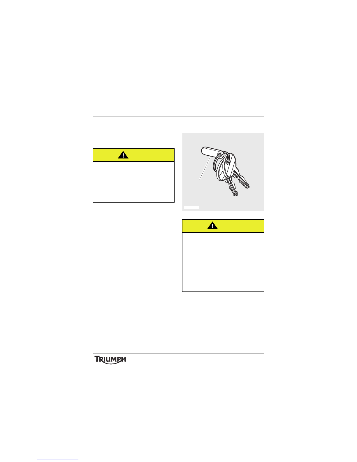
1. Steering lock key tag
The steering lock key operates the steering
lock only. A different key operates the ignition
switch.
When the motorcycle is delivered from the
factory, two steering lock keys are supplied
together with a small tag bearing the key
number. Make a note of the key number and
store the spare key and key number tag in a
safe place away from the motorcycle.
Caution
Additional keys or key rings attached to the
ignition key may cause damage to the
motorcycle’s painted or polished
components. Remove any such item from
the ignition key to prevent damage to
painted or polished components when the
motorcycle is ridden.
Caution
The ignition and steering lock keys are
different.
However, on some models the ignition and
steering lock keys will fit either lock, but
the keys will only operate their respective
locks.
Do not use the ignition key in the steering
lock, or the steering lock key in the ignition
switch as doing so may damage or break
the key or the steering lock/ignition switch.
T908012_1
1
Page 32
32
General Information
Your authorised Triumph dealer can supply a
replacement key cut from details of the key
number or can cut a new key using the
original as a master.
Steering Lock
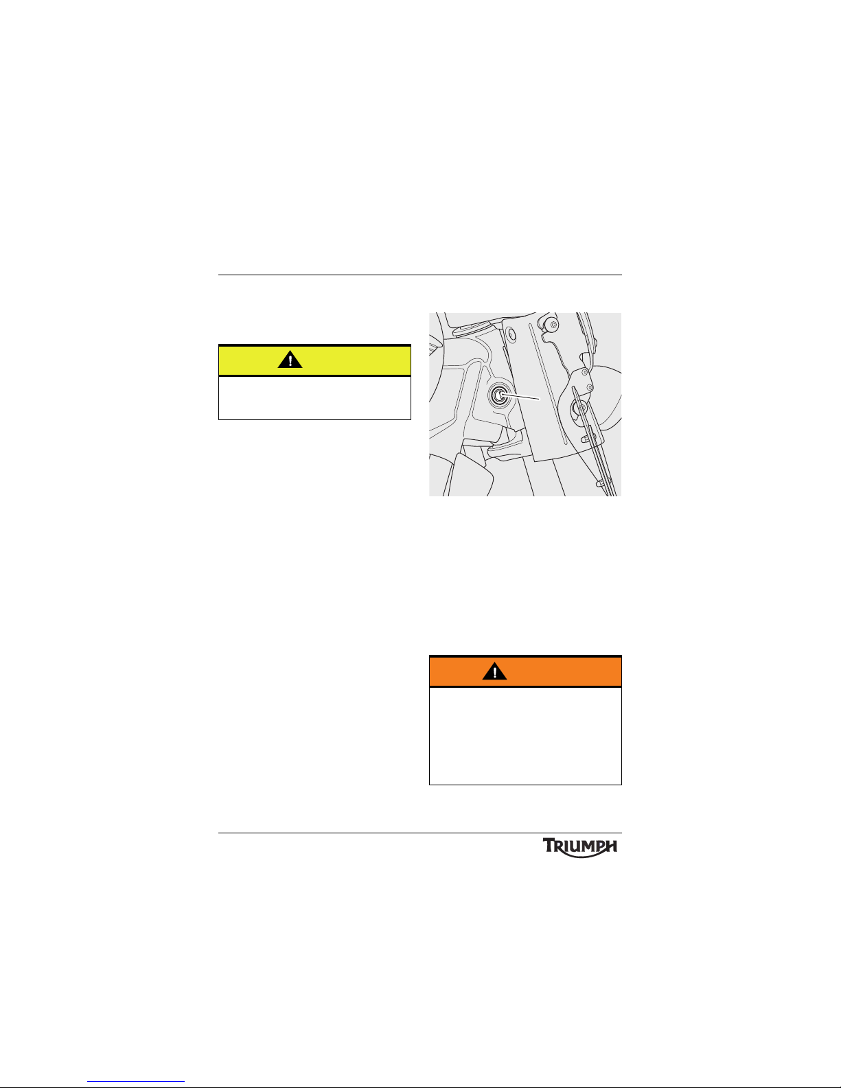
1. Steering lock
This is a two position, key operated lock. The
key can be removed in either the engaged or
disengaged positions.
To engage the lock, insert the key and turn
clockwise. At the same time, turn the
handlebars fully left until the lock engages.
To disengage the steering lock, insert the key,
turn the handlebars slightly to relieve any
weight on the lock and turn the key
anti-clockwise. Remove the key.
Caution
Do not store the spare key with the
motorcycle as this will reduce all aspects of
security.
Warning
Always disengage the steering lock before
riding as, with the steering lock engaged, it
will not be possible to turn the handlebars
or steer the motorcycle.
Riding without motorcycle steering control
will lead to loss of motorcycle control and
an accident.
cihc
1
Page 33
33
General Information
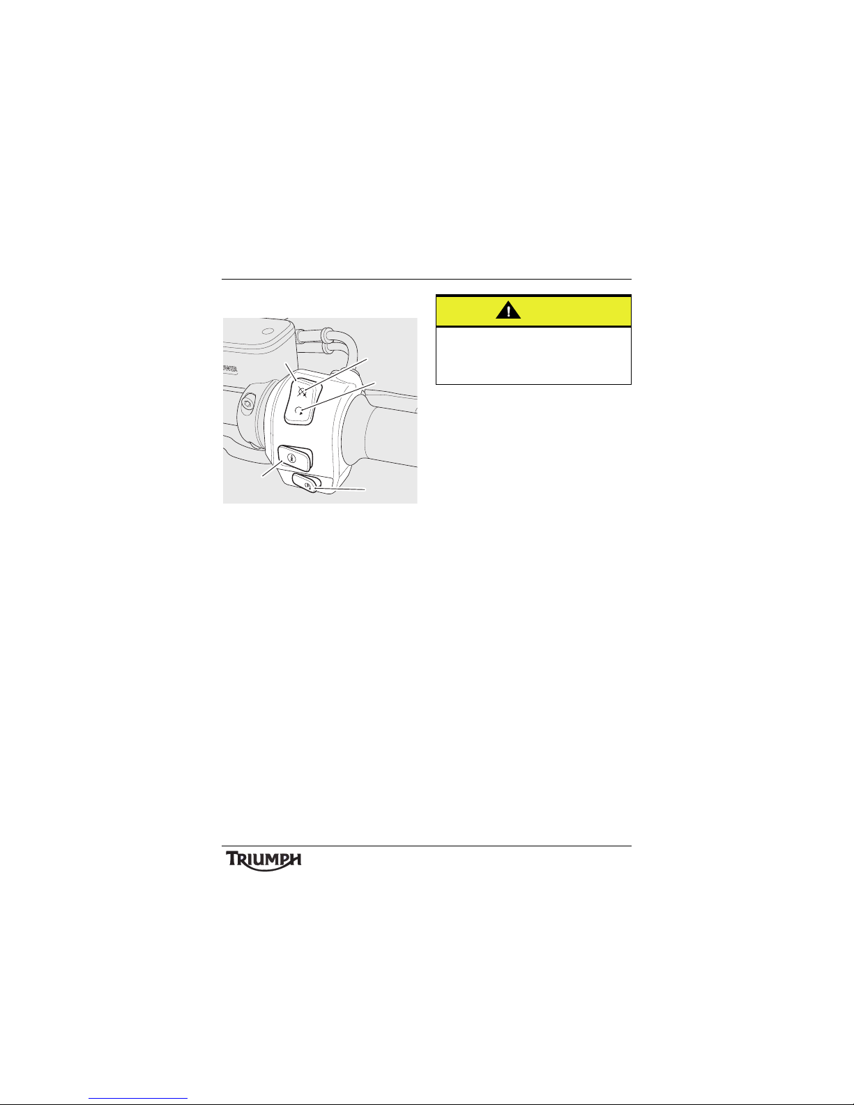
Right Handlebar Switches
1. Engine stop switch
2. STOP position
3. RUN position
4. Starter button
5. Scroll button
Engine Stop Switch
In addition to the ignition switch being turned
to the ON position, the engine stop switch
must be in the RUN position for the
motorcycle to operate.
The engine stop switch is for emergency use.
If an emergency arises which requires the
engine to be stopped, move the engine stop
switch to the STOP position.
Note:
• Although the engine stop switch
stops the engine, it does not turn off
all the electrical circuits and may
cause difficulty in restarting the
engine due to a discharged battery.
Ordinarily, only the ignition switch
should be used to stop the engine.
Starter Button
The starter button operates the electric
starter. For the starter to operate, the clutch
lever must be pulled to the handlebar.
Note:
• Even if the clutch lever is pulled to
the handlebar, the starter will not
operate if the side stand is down and
a gear is engaged.
Scroll Button
The scroll button is used to operate the
following functions of the instruments:
• Odometer functions (see page 24)
• Trip reset (see page 24)
• Clock reset (see page 25).
cfcc
1
2
3
4
5
Caution
Do not leave the ignition switch in the ON
position unless the engine is running as
this may cause damage to electrical
components and will discharge the battery.
Page 34
34
General Information
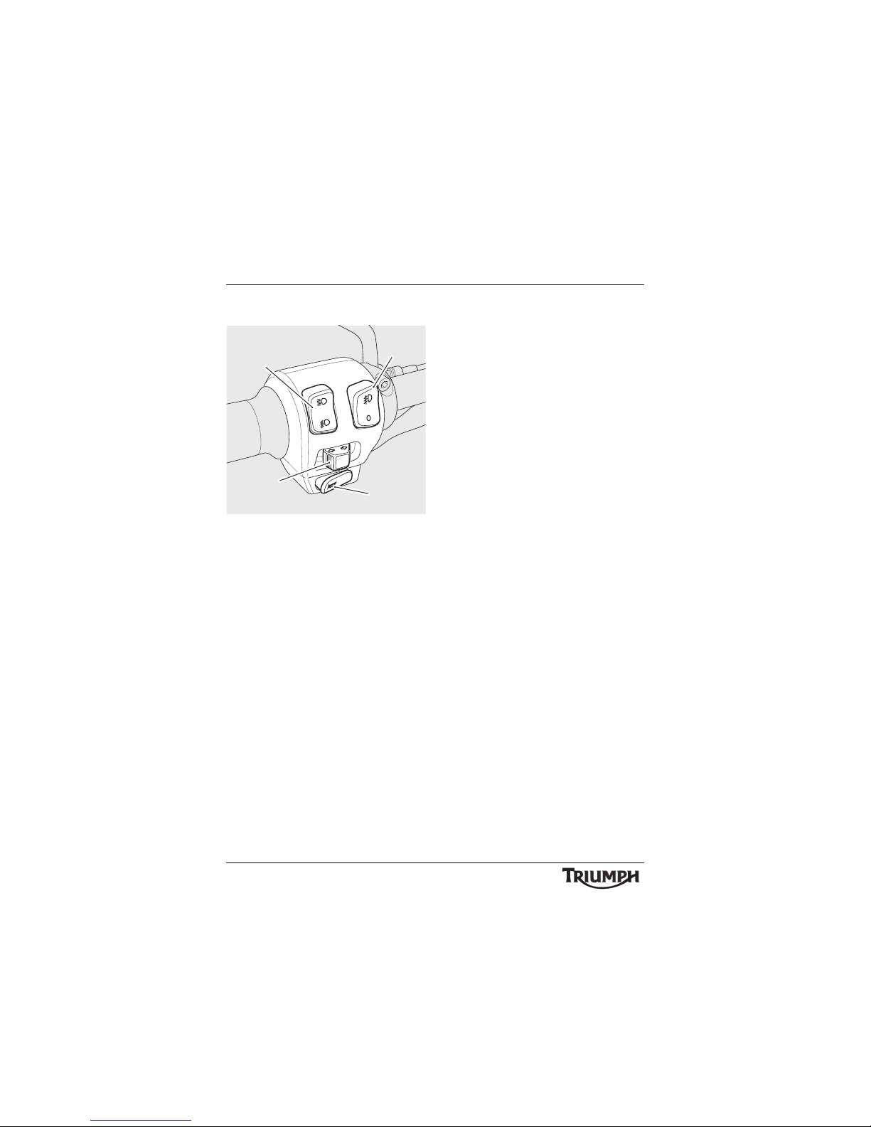
Left Handlebar Switches
1. Headlight dip switch
2. Direction indicator switch
3. Horn button
4. Fog light switch
Headlight Dip Switch
High or low beam can be selected with the
headlight dip switch. To select high beam,
push the switch forward. To select low beam,
push the switch rearwards. When the high
beam is turned on, the high beam indicator
light will illuminate.
Note:
• A lighting on/off switch is not fitted
to this model. The position light, rear
light and licence plate light all
function automatically when the
ignition is turned to the ON position.
• The headlight will only function
when the ignition switch is turned to
the ON position and the engine is
running.
An alternative to turn on the
headlight, without the engine
running, is to pull the clutch lever
then turn the ignition switch to the
ON position. The headlight will be
on and remain on when the clutch
lever is released.
The headlight will go off while
pressing the starter button until the
engine starts.
1
2
3
4
cfce
Page 35
35
General Information
Direction Indicator Switch
Note:
• This motorcycle is equipped with an
indicator self cancel system. The
system becomes active after
operating a direction indicator.
When the indicator switch is pushed to the
left or right, the corresponding direction
indicators will flash on and off. When the
indictor switch is released, the self cancel
system will become active.
Eight seconds after releasing the direction
indicator switch and when the motorcycle has
travelled a further 65 metres, the indicator
self cancel system will automatically turn off
the indicators.
The indicators can be cancelled manually. To
manually turn off the indicators, press and
release the indicator switch in the central
position.
Horn Button
When the horn button is pushed, with the
ignition switch turned to the ON position, the
horn will sound.
Fog Light Switch
The fog light switch is provided for the fog
lights that are fitted to Thunderbird LT.
When the fog lights are turned on, the fog
light indicator light in the instruments panel
will illuminate.
Due to the front headlight configuration,
Thunderbird Commander cannot have fog
lights fitted.
Fuel Requirement/Refuelling
Fuel Grade
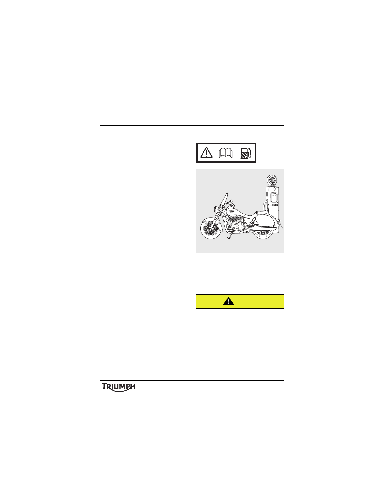
Your Triumph engine is designed to use
unleaded fuel and will give optimum
performance if the correct grade of fuel is
used. Always use unleaded fuel with a
minimum octane rating of 91 RON.
Caution
The exhaust system for this model is fitted
with a catalytic converter to help reduce
exhaust emission levels. The catalytic
converter can be permanently damaged if
the motorcycle is allowed to run out of fuel
or if the fuel level is allowed to get very
low. Always ensure you have adequate fuel
for your journey.
P
b
cfcu_1
Page 36
36
General Information
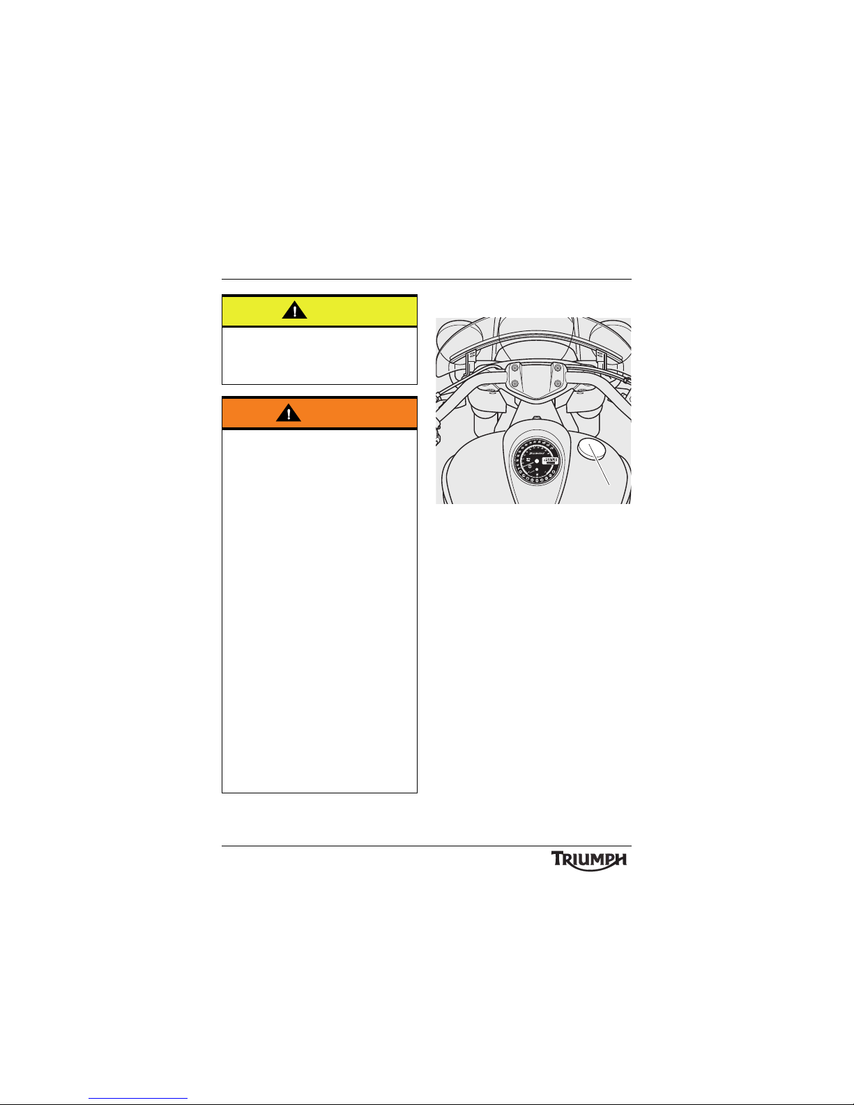
Fuel Tank Cap
1. F u e l t an k c a p
To open the fuel tank cap, rotate the cap
anti-clockwise and lift clear of the tank filler
neck.
To close the cap, align the cap to the tank
filler neck and rotate the cap clockwise until
the cap seals against the filler neck. In the
fully closed position, a ratchet mechanism
prevents over-tightening of the cap by
allowing the outer part of the cap to turn
independently of the internal part.
Caution
The use of leaded fuel is illegal in some
countries, states or territories. Use of
leaded fuel will damage the catalytic
converter.
Warning
To help reduce hazards associated with
refuelling, always observe the following
fuel safety instructions:
Petrol (fuel) is highly flammable and can be
explosive under certain conditions. When
refuelling, turn the ignition switch to the
OFF position.
Do not smoke.
Do not use a mobile telephone.
Make sure the refuelling area is well
ventilated and free from any source of
flame or sparks. This includes any
appliance with a pilot light.
Never fill the tank until the fuel level rises
into the filler neck. Heat from sunlight or
other sources may cause the fuel to
expand and overflow creating a fire
hazard.
After refuelling always check that the fuel
filler cap is correctly closed.
Because petrol (fuel) is highly flammable,
any fuel leak or spillage, or any failure to
observe the safety advice given above will
lead to a fire hazard, which could cause
damage to property, injury to persons or
death.
TRIP
1
2
1
Page 37
37
General Information
Filling the Fuel Tank
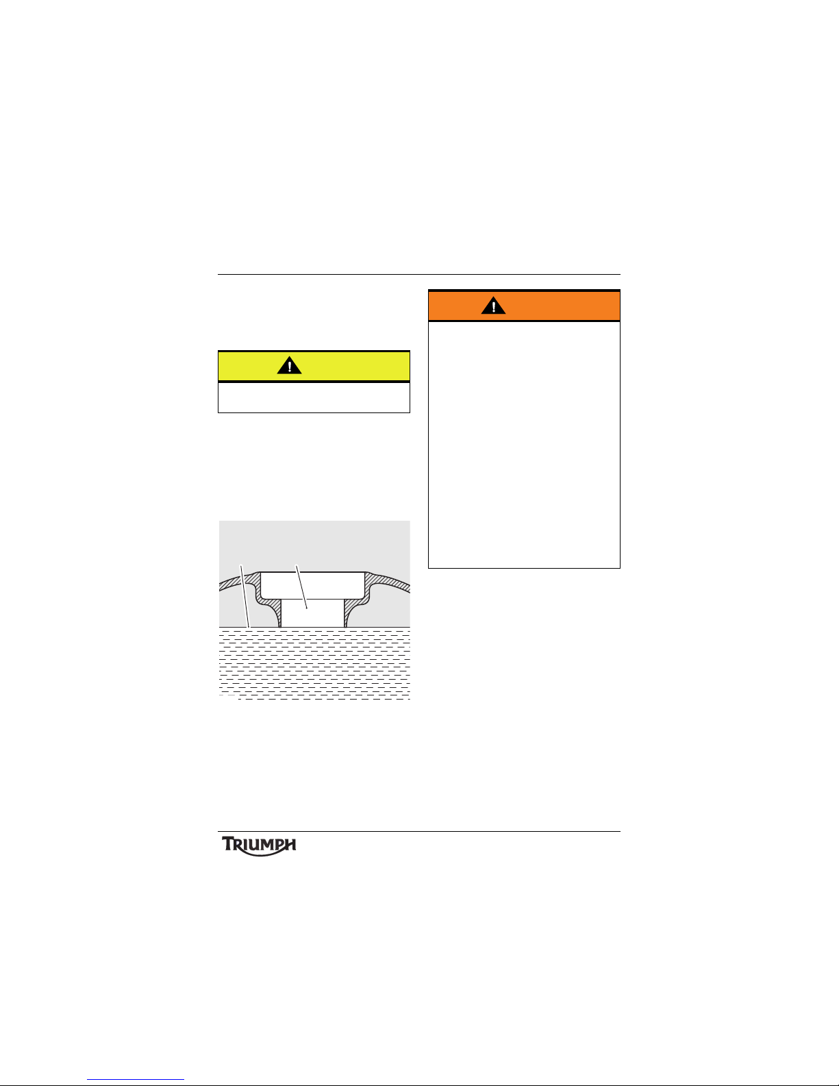
Avoid filling the tank in rainy or dusty
conditions where airborne material can
contaminate the fuel.
Fill the fuel tank slowly to help prevent
spillage. Do not fill the tank to a level above
the bottom of the filler neck. This will ensure
there is enough air space to allow for fuel
expansion if the fuel inside the tank expands
through absorption of heat from the engine
or from direct sunlight.
1. F u e l f il le r n e c k
2. Maximum fuel level
After refuelling always check that the fuel
filler cap is correctly closed.
Caution
Contaminated fuel may cause damage to
fuel system components.
cbnm
2 1
Warning
Overfilling the tank can lead to fuel
spillage.
If fuel is spilled, thoroughly clean up the
spillage immediately and dispose of the
materials used safely.
Take care not to spill any fuel on the
engine, exhaust pipes, tyres or any other
part of the motorcycle.
Because fuel is highly flammable, any fuel
leak or spillage, or any failure to observe
the safety advice given above may lead to
a fire hazard, which could cause damage to
property and injury or death to persons.
Fuel spilled near to, or onto the tyres will
reduce the tyre's ability to grip the road.
This will result in a dangerous riding
condition potentially causing loss of
motorcycle control and an accident.
Page 38
38
General Information
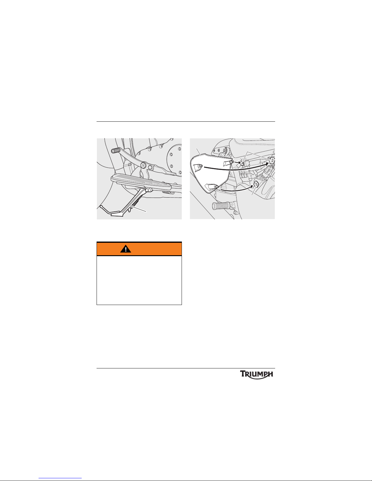
Side Stand
1. S i d e s ta n d
The motorcycle is equipped with a side stand
on which the motorcycle can be parked.
Note:
• When using the side stand, always
turn the handlebars fully to the left
and leave the motorcycle in first gear.
Whenever the side stand is used, before
riding, always ensure that the stand is fully up
after first sitting on the motorcycle.
For instructions on safe parking, refer to the
'How to Ride the Motorcycle' section.
Side Panels
1. Side panel (right hand shown)
2. Grommets
Side panel removal is required to access the
fuse box and the tool kit Allen key.
To remove either side panel, grasp the panel
firmly in both hands and pull the panel away
from the motorcycle until it clears the three
retaining grommets (leaving the grommets in
place).
To refit, position the three locating dowels to
the grommets, then press firmly to secure the
panel.
Ensure the panel is correctly located over the
upper and lower locating dowels.
Finally, grasp the panel and ensure that it is
fully retained.
Warning
The motorcycle is fitted with an interlock
system to prevent it from being ridden
with the side stand in the down position.
Never attempt to ride with the side stand
down or interfere with the interlock
mechanism as this will cause a dangerous
riding condition leading to loss of
motorcycle control and an accident.
cihb
1
1
2
2
cfhl
Page 39
39
General Information
Tool Kit and Handbook
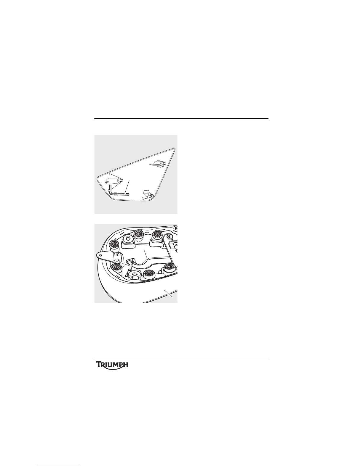
1. Allen key
1. Pillion seat
2. C-spanner
3. Wire clip
The tool kit consists of an Allen key for
removal of the rider and pillion seats and a
C-spanner for adjustment of the rear
suspension.
The Allen key is attached to the inside of the
left hand side panel.
The C-spanner is stored under the pillion
seat, behind the handbook. The spanner is
secured in position by a wire clip.
To gain access to the handbook, remove the
pillion seat (see page 40). The handbook is
located on the underside of the pillion seat.
Note:
• The fitting of some accessory kits
requires removal of the original
pillion seat, which houses the
handbook. In these circumstances,
ensure the Owner's Handbook is
removed from the pillion seat and
carried with the motorcycle at all
times.
cigu
1
cigt
3
2
1
Page 40
40
General Information
Seats
Seat Care
To prevent damage to the seats or seat
covers, care must be taken not to drop or
lean the seats against any surface which may
damage the seats or seat covers.
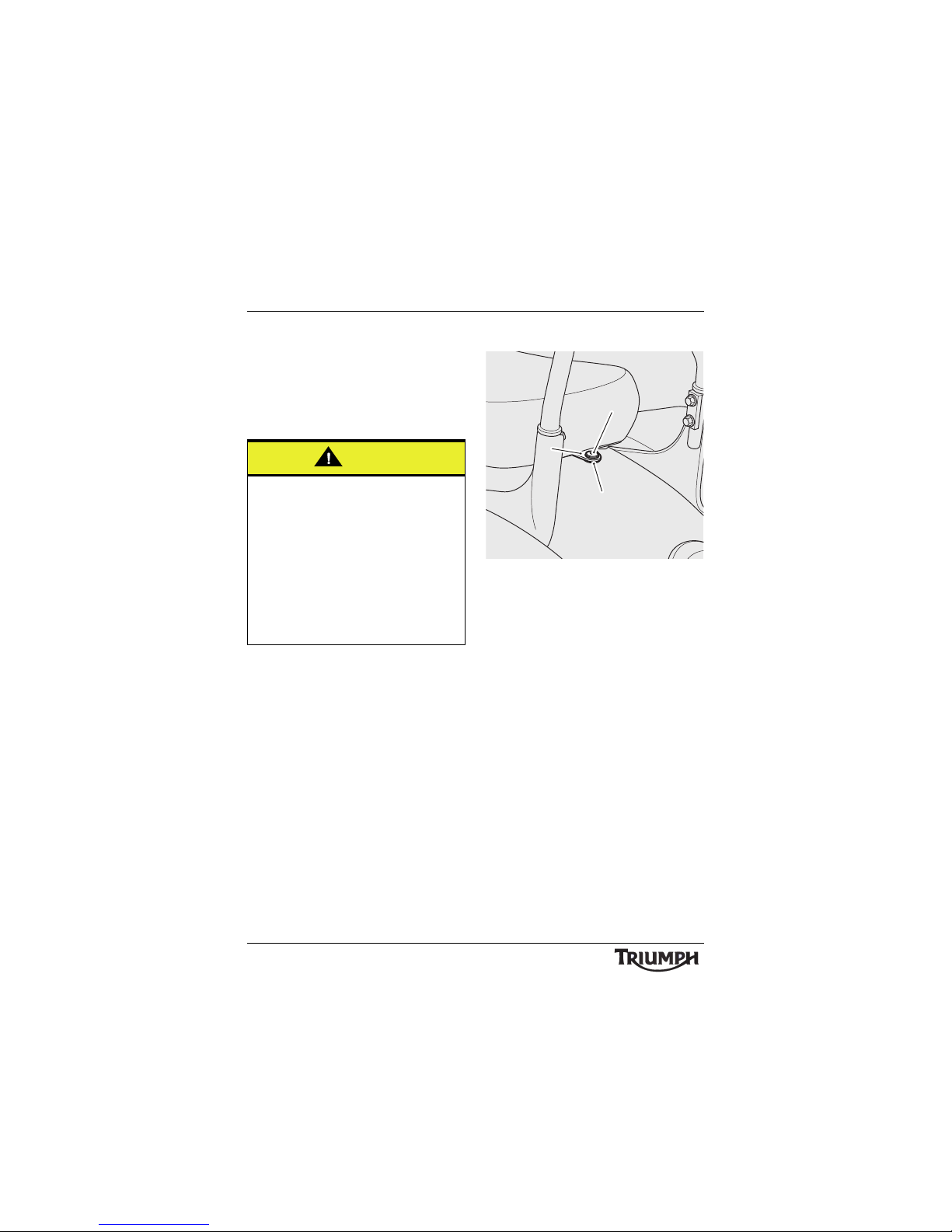
Pillion Seat Removal
1. Pillion seat fixing
2. Mounting bracket
3. Rubber washer
Note:
• Note the position of the rubber
washer between the pillion seat
mounting bracket and the rear
mudguard.
Caution
To prevent damage to the seats or seat
covers, care must be taken not to drop the
seats. Do not lean the seats against the
motorcycle or any surface which may
damage the seats or seat covers. Instead,
place the seats, with the seat cover facing
upwards, on a clean, flat surface which is
covered with a soft cloth.
Do not place any item on the seats which
may cause damage or staining to the seat
covers.
cigz
1
2
3
Page 41
41
General Information
To remove the pillion seat, remove the rear
fixing using the Allen key located on the
inside of the left hand side panel (see
page 39). Lift the seat up at the back for
complete removal from the motorcycle.
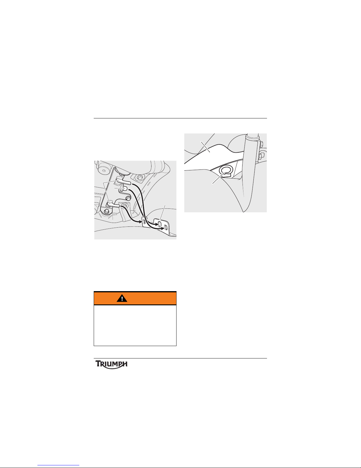
Collect the rubber washer.
1. Pillion seat hooks
2. Location peg
3. Pillion seat bracket
To refit the seat, engage the seat’s two hooks
and location pin into the bracket behind the
rider’s seat. Fit the rubber washer and fixing
as noted for removal. Tighten the fixing to
9Nm.
Rider Seat Removal
1. L o c k r el ea s e
2. Rider's seat
To remove the rider’s seat, remove the pillion
seat (see page 40).
Pull the lock release, located at the rear of the
seat, rearwards to release the seat from its
lock. Lift the seat up at the back for complete
removal from the motorcycle.
To refit the seat, engage the seat’s locating
tongue under the fuel tank.
Warning
To prevent detachment of the seat during
riding, after fitting always grasp the seat
and pull firmly upwards. If the seat is not
correctly secured it may detach from the
motorcycle. A loose or detached seat could
cause loss of motorcycle control and an
accident.
cfcn
1
2
3
ciha
2
1
Page 42
42
General Information
Note:
• An audible click can be heard when
the seat lock is engaged.
Press firmly down in the centre of the seat to
engage the seat lock.
Refit the pillion seat (see page 41 ).
Windscreen (if fitted)
Note:
• The windscreen can be removed
without the use of tools.
To Remove the Windscreen
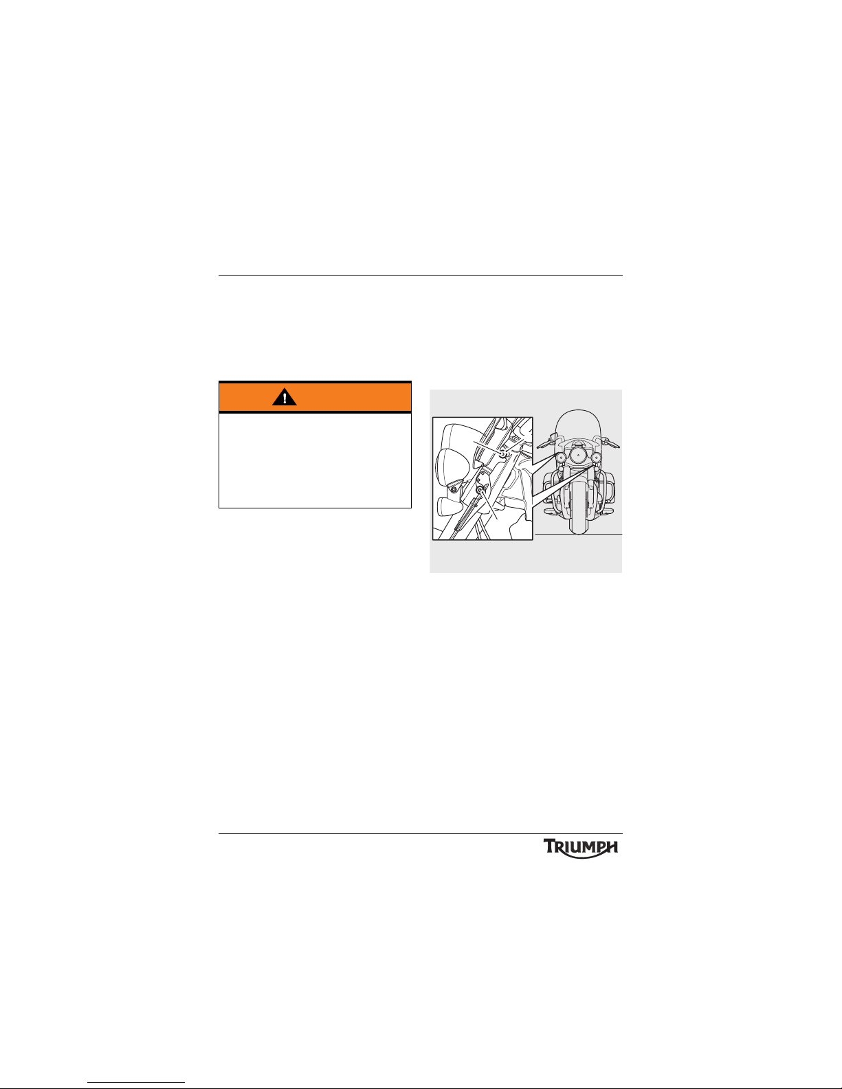
1. Upper mounting
2. Lower mounting
3. Latch
To remove the windscreen, stand astride the
front wheel and firmly grip both sides of the
windscreen close to the upper mounting.
Pull the windscreen firmly to disengage the
upper mountings.
Then lift the windscreen up to disengage the
lower mountings and completely remove
from the motorcycle.
Warning
To prevent detachment of the seat during
riding, after fitting always grasp the seat
and pull firmly upwards. If the seat is not
correctly secured it may detach from the
motorcycle. A loose or detached seat could
cause loss of motorcycle control and an
accident.
cigw
2
3
1
Page 43
43
General Information
To Install the Windscreen
To install the windscreen, stand astride the
front wheel and align the windscreen lower
mounting slots to the lower mountings on
the front forks.
Note:
• An audible click can be heard when
the windscreen upper mountings are
fully engaged.
Align the windscreen upper mounting slots
with their upper mountings on the front
forks. With a firm push, fully engage the
upper mountings.
Ensure both of the upper mounting latches
are fully engaged round the mountings.
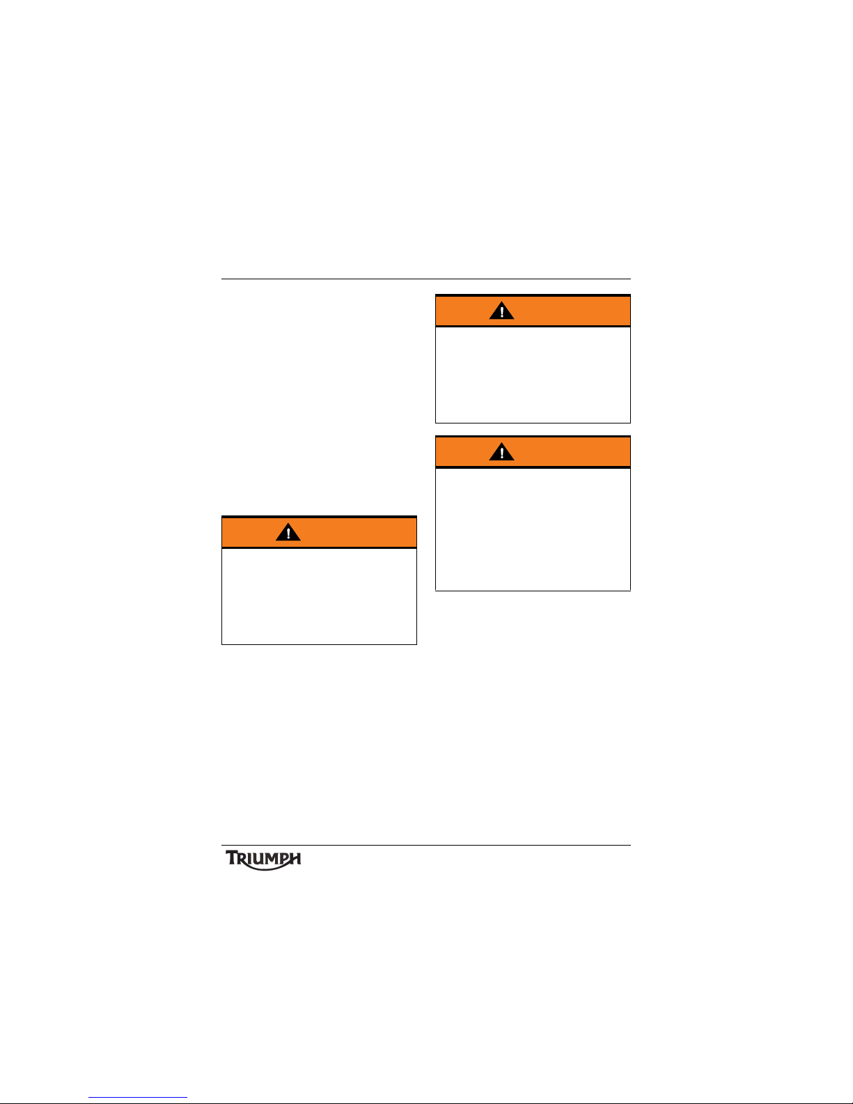
Warning
To prevent detachment of the windscreen
during riding, after fitting always grasp the
windscreen and pull firmly upwards. If the
windscreen is not correctly secured it may
detach from the motorcycle. A loose or
detached windscreen could cause loss of
motorcycle control and an accident.
Warning
After fitting or removing the windscreen,
operate the motorcycle in a safe area free
from traffic to gain familiarity with any new
characteristics. Operation of the motorcycle
when not familiar with any new handling
characteristics may result in loss of
motorcycle control and an accident.
Warning
Never attempt to clean or adjust the
windscreen while riding the motorcycle.
Removal of the rider's hands from the
handlebars while riding the motorcycle will
diminish the ability of the rider to maintain
the control of the motorcycle. Attempting
to clean or adjust the windscreen while
riding the motorcycle may result in loss of
motorcycle control and an accident.
Page 44
44
General Information
Panniers (if fitted)
To Remove the Panniers
Note:
• The same procedure can be
followed to remove and mount the
left or right hand pannier.
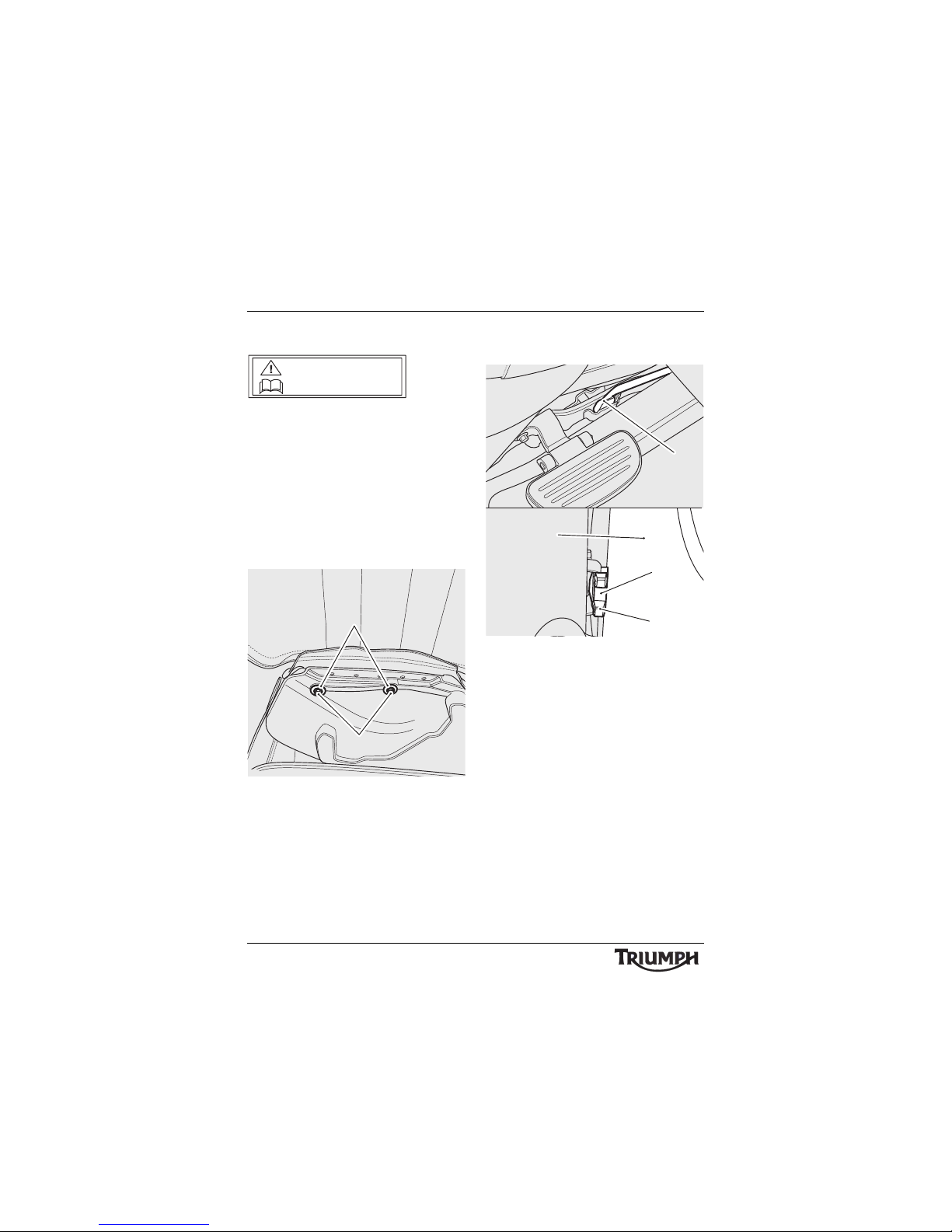
To remove the pannier from the motorcycle,
open the lid of the pannier and remove the
two fixings and their washer. Keep the fixings
and washers with the pannier.
1. Fixings
2. Washers
Pull the top of the pannier away from its
mounting studs.
Lift up the front of the pannier to disengage it
from the front mounting.
Slide the pannier forwards to disengage from
the rear mounting and remove the pannier.
1. Rear mounting
2. Flanged sleeve
3. Rear mudguard
4. Front mounting
MAX LOAD
7.0 kg (15.4lbs)
cigx
2
1
1
2
3
4
Page 45
45
General Information
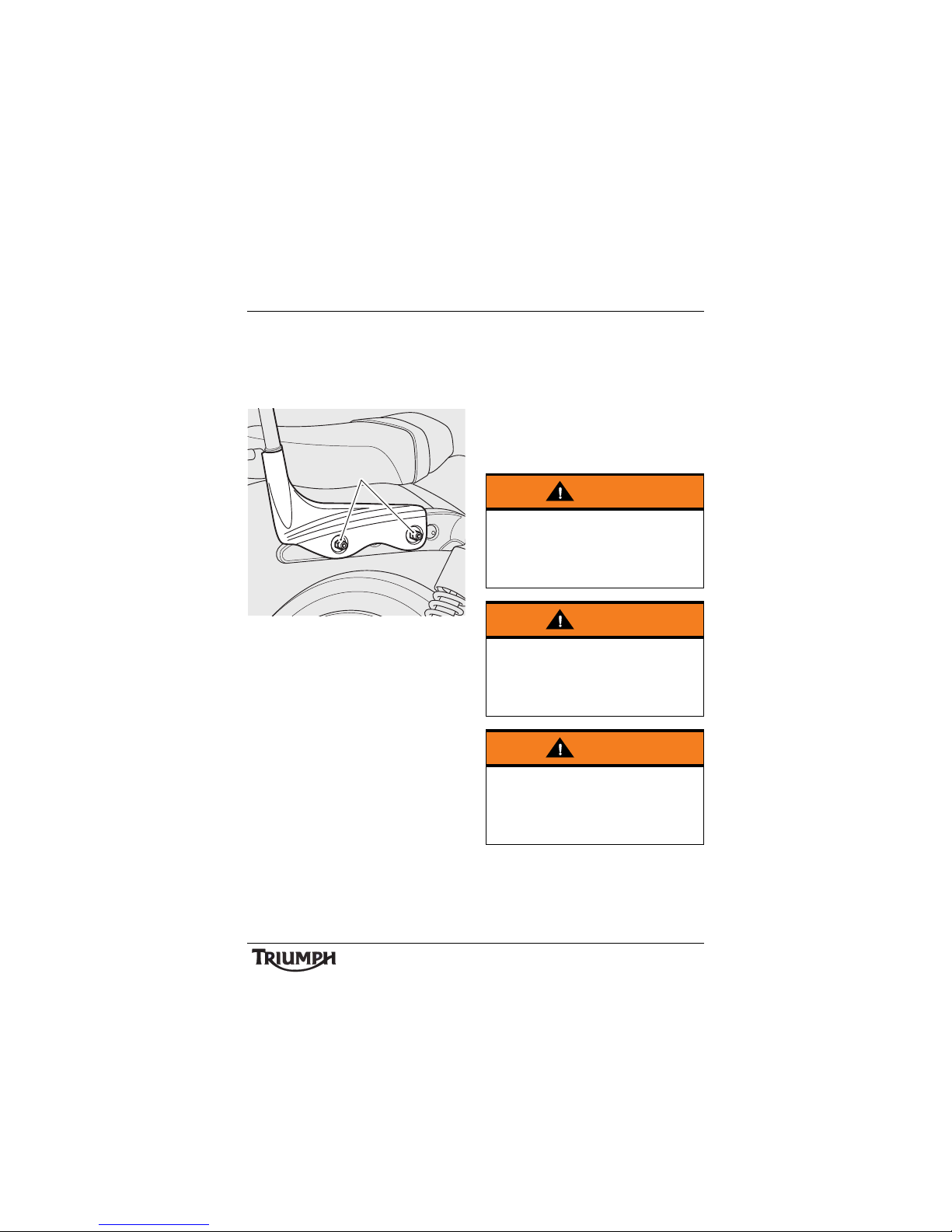
When the panniers have been removed, and
prior to installing the panniers, ensure that
the two mounting studs, shown in the
following illustration, are secure and
tightened to 20 Nm.
1. Pannier mountings studs
To Install the Panniers
Align the rear mounting to the flanged sleeve
on the rear mudguard. Slide the pannier
rearwards to fully engage on to it.
Fit the front mounting to its slot on the frame
of the motorcycle.
Align the top of the pannier to its mounting
studs and fit the washers and fixings. Tighten
the fixings to 15 N m .
cihq
1
Warning
Always ensure that the front and rear
mountings of the panniers are correctly
fitted and the fixings are secure. A loose or
detached pannier could cause loss of
motorcycle control and an accident.
Warning
Always ensure the pannier lids are securely
closed on both latches. An open pannier
lid may cause the motorcycle to become
unstable leading to loss of motorcycle
control and an accident.
Warning
The maximum safe load for each pannier
is 7.0 kg (15.4 lbs). Never exceed this
loading limit as this may cause the
motorcycle to become unstable leading to
loss of motorcycle control and an accident.
Page 46
46
General Information
For information on cleaning and care for the
leather panniers, see page 115 .
Warning
Incorrect loading may result in an unsafe
riding condition leading to an accident.
Always ensure any loads carried are evenly
distributed on both sides of the motorcycle.
Ensure that the load is correctly secured
such that it will not move around while the
motorcycle is in motion.
Always check the load security regularly
(though not while the motorcycle is in
motion) and ensure that the load does not
extend beyond the rear of the motorcycle.
Never exceed the maximum vehicle
loading weight of:
• 220 kg for Thunderbird LT.
• 232 kg for Thunderbird Commander.
This maximum loading weight is made up
from the combined weight of the rider,
passenger, any accessories fitted and any
load carried in the panniers.
Warning
After fitting or removing the panniers,
operate the motorcycle in a safe area free
from traffic to gain familiarity with the new
handling characteristics. Operation when
not familiar with the new characteristics of
the motorcycle may result in loss of
motorcycle control and an accident.
Page 47

47
General Information
Running-In
Running-in is the name given to the process
that occurs during the first hours of a new
vehicle's operation.
In particular, internal friction in the engine will
be higher when components are new. Later
on, when continued operation of the engine
has ensured that the components have
'bedded in', this internal friction will be
greatly reduced.
A period of careful running-in will ensure
lower exhaust emissions, and will optimise
performance, fuel economy and longevity of
the engine and other motorcycle components.
During the first 500 miles (800 km):
• Do not use full throttle;
• Avoid high engine speeds at all times;
• Avoid riding at one constant engine
speed, whether fast or slow, for a long
period of time;
• Avoid aggressive starts, stops, and rapid
accelerations, except in an emergency;
• Do not ride at speeds greater than 3/4 of
maximum speed.
From 500 to 1,000 miles (800 to 1,500 km):
• Engine speed can gradually be increased
to the rev limit for short periods.
Both during and after running-in has been
completed:
• Do not over-rev the engine when cold;
• Do not let the engine labour. Always
downshift before the engine begins to
'struggle';
• Do not ride with engine speeds
unnecessarily high. Changing up a gear
helps reduce fuel consumption, reduces
noise and helps to protect the
environment.
Page 48
48
General Information
Safe Operation
Daily Safety Checks
Check the following items each day before
you ride. The time required is minimal, and
these checks will help ensure a safe, reliable
ride.
If any irregularities are found during these
checks, refer to the Maintenance and
Adjustment section or see your authorised
Triumph dealer for the action required to
return the motorcycle to a safe operating
condition.
Check:
Fuel: Adequate supply in tank, no fuel leaks
(page 37).
Engine Oil: Correct level on dipstick. Add
correct specification oil as required. No leaks
from the engine or oil cooler (page 71 ).
Drive Belt: Correct adjustment. No
damage/cuts, frayed edges or broken teeth
(page 90).
Tyres/Wheels: Correct inflation pressures
(when cold). Tread depth/wear, tyre/wheel
damage, loose/broken spokes, punctures etc.
(page 98).
Nuts, Bolts, Fasteners: Visually check that
steering and suspension components, axles,
and all controls are properly tightened or
fastened. Inspect all areas for loose/damaged
fixings.
Steering Action: Smooth but not loose from
lock to lock. No binding of any of the control
cables (page 86).
Brakes: Pull the brake lever and push the
brake pedal to check for correct resistance.
Investigate any lever/pedal where the travel is
excessive before meeting resistance, or if
either control feels spongy in operation
(page 82).
Brake Pads: There should be more than
1.5 mm of friction material remaining on all
the pads (page 82).
Brake Fluid Levels: No brake fluid leakage.
Brake fluid levels must be between the MAX
and MIN marks on both reservoirs
(page 84).
Front Forks: Smooth action. No fork oil
leakage (page 88).
Throttle: Throttle grip free play 2 - 3 mm.
Ensure that the throttle grip returns to the
idle position without sticking (page 78).
Clutch: Smooth operation and correct cable
free play (page 81 ).
Coolant: No coolant leakage. Check the
coolant level in the expansion tank (when the
engine is cold) (see page 74 ).
Electrical Equipment: All lights and horn
function correctly (page 33).
Engine Stop: Stop switch turns the engine
off (page 33).
Stand: Returns to the fully up position by
spring tension. Return springs not weak or
damaged (page 38).
Warning
Failure to perform these checks every day
before you ride may result in serious
motorcycle damage, loss of motorcycle
control and an accident.
DAILY SAFETY CHECKS AND SEAT CARE
CONTRÔLES DE SÉCURITÉ QUOTIDIEN ET NETT OYAGE DE LA SELLE
COMPROBACIONES DIARIAS Y EL MANTENIMIENTO DE SU ASIENTO
DAGELIJKSE VEILIGHEIDSCONTROLE S EN Z ADELONDERHOUD
TÄGLICHE SICHERHEITS KONTROLLEN UND PFLEGE DES SITZES
DAGLIGA SÄKERHETSKONTROLLER OCH VÅRD AV SADEL
CONTROLLI DI SICUREZZA GIORNALIERI E PULIZIA SELLA
日常安全点検とシートのお手入れ
Page 49

How to Ride the Motorcycle
49
HOW TO RIDE THE MOTORCYCLE
Table of Contents
To Stop the Engine . . . . . . . . . . . . . . . . . . . . . . . . . . . . . . . . . . . . . . . . . . . . . . . . . . . . . . . . . . . 50
To Start the Engine . . . . . . . . . . . . . . . . . . . . . . . . . . . . . . . . . . . . . . . . . . . . . . . . . . . . . . . . . . . 50
Moving Off . . . . . . . . . . . . . . . . . . . . . . . . . . . . . . . . . . . . . . . . . . . . . . . . . . . . . . . . . . . . . . . . . 51
Changing Gears . . . . . . . . . . . . . . . . . . . . . . . . . . . . . . . . . . . . . . . . . . . . . . . . . . . . . . . . . . . . . 52
Braking . . . . . . . . . . . . . . . . . . . . . . . . . . . . . . . . . . . . . . . . . . . . . . . . . . . . . . . . . . . . . . . . . . . . 53
ABS (Anti-Lock Brake System) . . . . . . . . . . . . . . . . . . . . . . . . . . . . . . . . . . . . . . . . . . . . . . 55
Parking . . . . . . . . . . . . . . . . . . . . . . . . . . . . . . . . . . . . . . . . . . . . . . . . . . . . . . . . . . . . . . . . . . . . 56
Considerations for High-Speed Operation . . . . . . . . . . . . . . . . . . . . . . . . . . . . . . . . . . . . . . . . 57
General . . . . . . . . . . . . . . . . . . . . . . . . . . . . . . . . . . . . . . . . . . . . . . . . . . . . . . . . . . . . . . . . 58
Steering . . . . . . . . . . . . . . . . . . . . . . . . . . . . . . . . . . . . . . . . . . . . . . . . . . . . . . . . . . . . . . . . 58
Luggage. . . . . . . . . . . . . . . . . . . . . . . . . . . . . . . . . . . . . . . . . . . . . . . . . . . . . . . . . . . . . . . . 58
Brakes . . . . . . . . . . . . . . . . . . . . . . . . . . . . . . . . . . . . . . . . . . . . . . . . . . . . . . . . . . . . . . . . . 58
Tyres . . . . . . . . . . . . . . . . . . . . . . . . . . . . . . . . . . . . . . . . . . . . . . . . . . . . . . . . . . . . . . . . . . . 58
Fuel. . . . . . . . . . . . . . . . . . . . . . . . . . . . . . . . . . . . . . . . . . . . . . . . . . . . . . . . . . . . . . . . . . . . 59
Engine Oil . . . . . . . . . . . . . . . . . . . . . . . . . . . . . . . . . . . . . . . . . . . . . . . . . . . . . . . . . . . . . . 59
Drive Belt . . . . . . . . . . . . . . . . . . . . . . . . . . . . . . . . . . . . . . . . . . . . . . . . . . . . . . . . . . . . . . . 59
Coolant . . . . . . . . . . . . . . . . . . . . . . . . . . . . . . . . . . . . . . . . . . . . . . . . . . . . . . . . . . . . . . . . 59
Electrical Equipment . . . . . . . . . . . . . . . . . . . . . . . . . . . . . . . . . . . . . . . . . . . . . . . . . . . . . . 59
Miscellaneous . . . . . . . . . . . . . . . . . . . . . . . . . . . . . . . . . . . . . . . . . . . . . . . . . . . . . . . . . . . 59
Page 50
50
How to Ride the Motorcycle
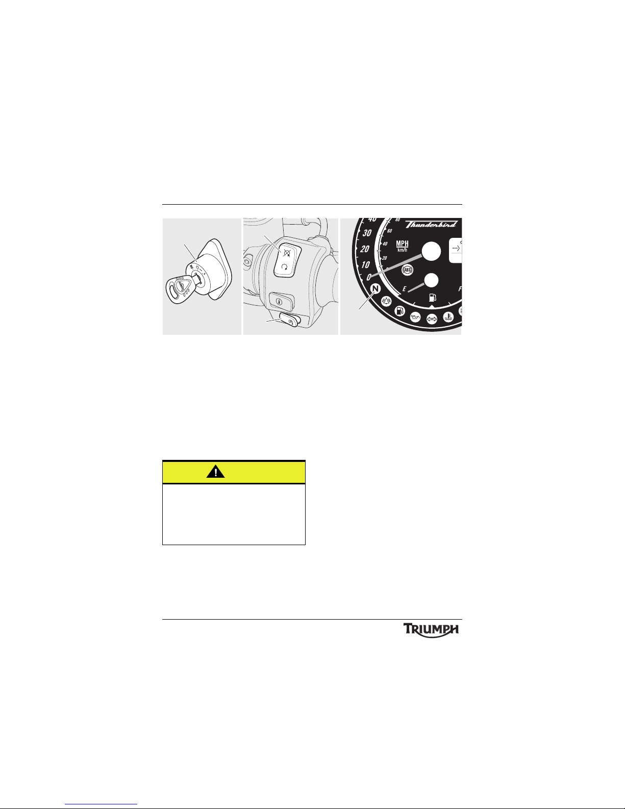
1. Ignition switch
2. Engine stop switch
3. Starter button
4. Neutral light
To Stop the Engine
Close the throttle completely.
Select neutral.
Turn the ignition switch off.
Select first gear.
Support the motorcycle on a firm, level
surface with the side stand (see page 56).
Lock the steering (see page 31 ).
To Start the Engine
Check that the engine stop switch is in the
RUN position.
Ensure the transmission is in neutral.
Turn the ignition switch on.
Note:
• When the ignition is switched on,
the instrument warning lights will
illuminate and will then go off
(except those which normally
remain on until the engine starts see 'Warning Lights' on page 26).
• A transponder is fitted within the key
to turn off the engine immobiliser. To
ensure the immobiliser functions
correctly, always have only one of
the ignition keys near the ignition
switch. Having two ignition keys near
the switch may interrupt the signal
between the transponder and the
engine immobiliser. In this situation
the engine immobiliser will remain
active until one of the ignition keys is
removed.
cfcv
P
TRIP
1
1
2
3
4
Caution
The engine should normally be stopped by
turning the ignition switch to the OFF
position. The engine stop switch is for
emergency use only. Do not leave the
ignition switched on with the engine
stopped. Electrical damage may result.
Page 51
51
How to Ride the Motorcycle
Pull the clutch lever fully into the handlebar.
Leaving the throttle fully closed, push the
starter button until the engine starts.
• The motorcycle is equipped with starter
lockout switches. The switches prevent
the electric starter from operating when
the transmission is not in neutral with the
side stand down.
• If the side stand is extended whilst the
engine is running, and the transmission
is not in neutral then the engine will stop
regardless of clutch position.
Moving Off
Pull in the clutch lever and select first gear.
Open the throttle a little and let out the clutch
lever slowly. As the clutch starts to engage,
open the throttle a little more, allowing
enough engine speed to avoid stalling.
Warning
Never start the engine or run the engine in
a confined area. Exhaust fumes are
poisonous and can cause loss of
consciousness and death within a short
period of time. Always operate your
motorcycle in the open-air or in an area
with adequate ventilation.
Caution
Do not operate the starter continuously for
more than 5 seconds as the starter motor
will overheat and the battery will become
discharged. Wait 15 seconds between each
operation of the starter to allow for cooling
and recovery of battery power.
Do not let the engine idle for long periods
as this may lead to overheating which will
cause damage to the engine.
Caution
The low oil pressure warning light should
go out shortly after the engine starts.
If the low oil pressure warning light stays
on after starting the engine, stop the
engine immediately and investigate the
cause. Running the engine with low oil
pressure will cause severe engine damage.
Page 52
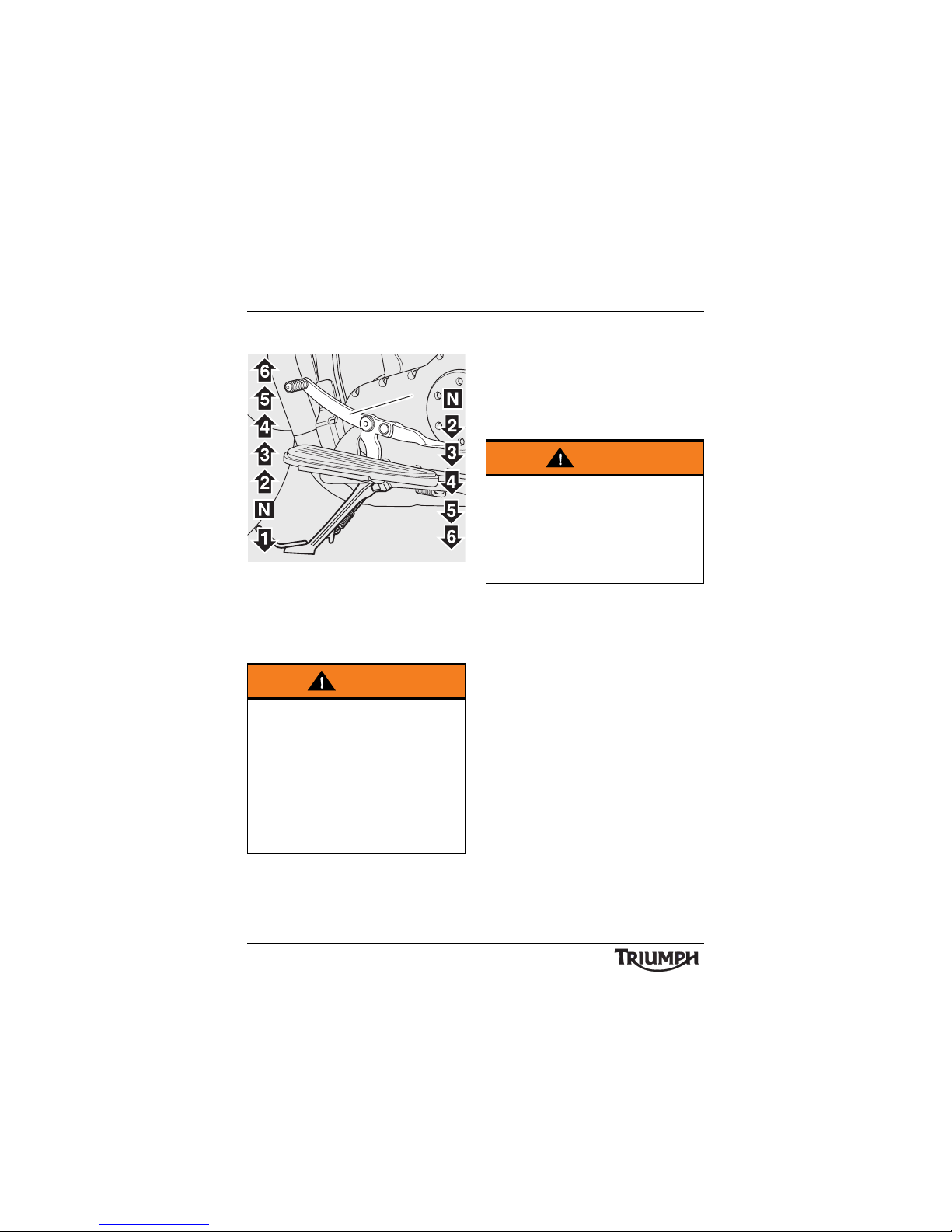
52
How to Ride the Motorcycle
Changing Gears
1. Gear change pedal
Close the throttle while pulling in the clutch
lever. Change into the next higher or lower
gear. Open the throttle part way, while
releasing the clutch lever. Always use the
clutch when changing gear.
Note:
• The gear change mechanism is the
'positive stop' type. This means that,
for each movement of the gear
change pedal/lever, you can only
select each gear, one after the other,
in ascending or descending order.
Warning
Take care to avoid opening the throttle too
far or too fast in any of the lower gears as
this can lead to the front wheel lifting from
the ground (pulling a 'wheelie') and to the
rear tyre breaking traction (wheel spin).
Always open the throttle cautiously,
particularly if you are unfamiliar with the
motorcycle, as a 'wheelie' or loss of traction
will cause loss of motorcycle control and an
accident.
cihb
1
Warning
Do not change to a lower gear at speeds
that will cause excessive engine
rpm (r/min). This can lock the rear wheel
causing loss of control and an accident.
Engine damage may also be caused.
Changing down should be done such that
low engine speeds will be ensured.
Page 53
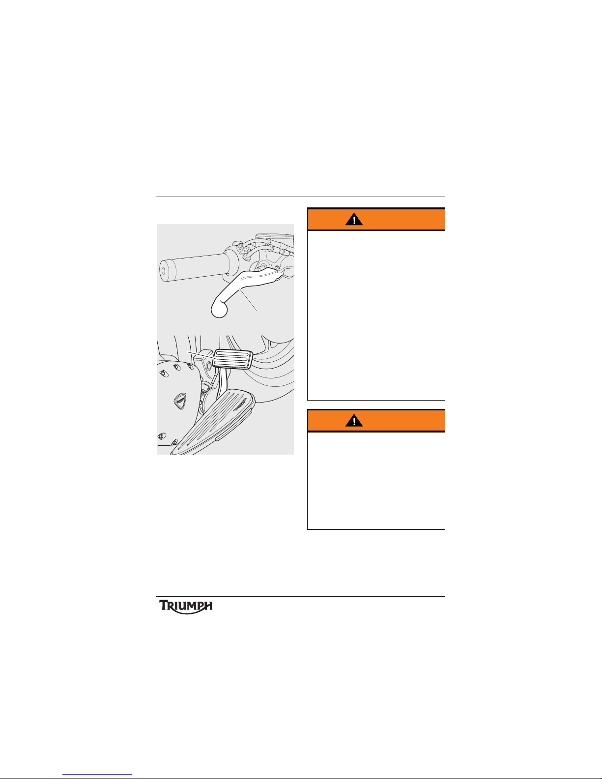
53
How to Ride the Motorcycle
Braking
1. Front brake lever
2. Rear brake pedal
cfcq
1
2
Warning
WHEN BRAKING, OBSERVE THE
FOLLOWING:
Close the throttle completely, leaving the
clutch engaged to allow the engine to help
slow down the motorcycle.
Change down one gear at a time such that
the transmission is in first gear when the
motorcycle comes to a complete stop.
When stopping, always apply both brakes
at the same time. Normally the front brake
should be applied a little more than the
rear.
Change down or fully disengage the clutch
as necessary to keep the engine from
stalling.
Never lock the brakes, as this may cause
loss of motorcycle control and an accident.
Warning
For emergency braking, disregard down
changing, and concentrate on applying the
front and rear brakes as hard as possible
without skidding. Riders should practice
emergency braking in a traffic-free area.
Triumph strongly recommends that all
riders take a course of instruction, which
includes advice on safe brake operation.
Incorrect brake technique could result in
loss of motorcycle control and an accident.
Page 54
54
How to Ride the Motorcycle
Warning
For your safety, always exercise extreme
caution when braking, accelerating or
turning as any incautious action can cause
loss of motorcycle control and an accident.
Independent use of the front or rear brakes
reduces overall braking performance.
Extreme braking may cause either wheel
to lock, reducing control of the motorcycle
and causing an accident (see ABS
warnings below).
When possible, reduce speed or brake
before entering a turn as closing the
throttle or braking in mid-turn may cause
wheel slip leading to loss of motorcycle
control and an accident.
When riding in wet or rainy conditions, or
on loose surfaces, the ability to manoeuvre
and stop will be reduced. All of your
actions should be smooth under these
conditions. Sudden acceleration, braking or
turning may cause loss of motorcycle
control and an accident.
Warning
When descending a long steep gradient,
use engine braking by down changing and
use the brakes intermittently. Continuous
brake application can overheat the brakes
and reduce their effectiveness.
Riding with your foot on the brake pedal
or your hands on the brake lever may
actuate the brake light, giving a false
indication to other road users. It may also
overheat the brake, reducing braking
effectiveness.
Do not coast with the engine switched off,
and do not tow the motorcycle. The
transmission is pressure-lubricated only
when the engine is running. Inadequate
lubrication may cause damage or seizure
of the transmission, which can lead to
sudden loss of motorcycle control and an
accident.
Page 55
55
How to Ride the Motorcycle
ABS (Anti-Lock Brake System)
ABS Warning Light
The ABS indicator light
illuminates to show that the ABS
function is not available.
Illumination is normal after engine start-up,
and until the motorcycle first reaches a speed
exceeding 6 mph (10 km/h). Unless there is
a fault, it should not illuminate again until the
engine is restarted.
If the indicator light becomes illuminated at
any other time while riding, it indicates that
the ABS has a malfunction that requires
investigation.
Note:
• Normally, the rider will perceive
ABS operation as a harder feel or a
pulsation of the brake lever and
pedal. As the ABS is not an
integrated braking system and it
does not control both the front and
rear brake at the same time, this
pulsation may be felt in the lever,
the pedal or both.
• The ABS may be activated by
sudden upward or downward
changes in the road surface.
Warning
ABS prevents the wheels from locking,
therefore maximising the effectiveness of
the braking system in emergencies and
when riding on slippery surfaces. The
potentially shorter braking distances ABS
allows under certain conditions are not a
substitute for good riding practice.
Always ride within the legal speed limit.
Never ride without due care and attention
and always reduce speed in consideration
of weather, road and traffic conditions.
Take care when cornering. If the brakes are
applied in a corner, ABS will not be able to
counteract the weight and momentum of
the motorcycle. This can result in loss of
motorcycle control and an accident.
Under some circumstances it is possible
that a motorcycle equipped with ABS may
require a longer stopping distance than an
equivalent motorcycle without ABS.
Warning
If the ABS is not functioning, the brake
system will continue to function as a
non-ABS braking system. Do not continue
to ride for longer than is necessary with the
indicator light illuminated. Contact an
authorised Triumph dealer as soon as
possible to have the fault checked and
rectified. In this situation, braking too hard
will cause the wheels to lock resulting in
loss of motorcycle control and an accident.
Page 56
56
How to Ride the Motorcycle
Parking
Select neutral and turn the ignition switch to
the OFF position.
Lock the steering to help prevent theft.
Always park on a firm, level surface to
prevent the motorcycle from falling.
When parking on a hill, always park facing
uphill to prevent the motorcycle from rolling
off the stand. Engage first gear to prevent the
motorcycle from moving.
On a lateral (sideways) incline, always park
such that the incline naturally pushes the
motorcycle towards the sidestand.
Do not park on a lateral (sideways) incline of
greater than 6° and never park facing
downhill.
Note:
• When parking near traffic at night,
or when parking in a location where
parking lights are required by law,
leave the tail, licence plate and
position lights on by turning the
ignition switch to P (PARK).
Warning
The ABS warning light will illuminate when
the rear wheel is driven at high speed for
more than 30 seconds when the
motorcycle is on a stand. This reaction is
normal.
When the ignition is switched off and the
motorcycle is re-started, the warning light
will illuminate until the motorcycle reaches
a speed exceeding 19 mph (30 km/h).
Warning
The ABS computer operates by comparing
the relative speed of the front and rear
wheels. Use of non-recommended tyres
can affect wheel speed and cause the ABS
function not to operate, potentially leading
to loss of control and an accident in
conditions where the ABS would normally
function.
Page 57
57
How to Ride the Motorcycle
Do not leave the switch in the P position for
long periods of time as this will discharge the
battery.
Ensure that the side stand is fully retracted
before riding off.
Considerations for
High-Speed Operation
Warning
Do not park on a soft or on a steeply
inclined surface. Parking under these
conditions may cause the motorcycle to fall
over causing damage to property and
personal injury.
Warning
Petrol is extremely flammable and can be
explosive under certain conditions. If
parking inside a garage or other structure,
be sure it is well ventilated and the
motorcycle is not close to any source of
flame or sparks. This includes any
appliance with a pilot light.
Failure to follow the above advice may
cause a fire resulting in damage to
property or personal injury.
Warning
The engine and exhaust system will be hot
after riding. DO NOT park where
pedestrians and children are likely to touch
the motorcycle.
Touching any part of the engine or exhaust
system when hot may cause unprotected
skin to become burnt.
Warning
This Triumph motorcycle should be
operated within the legal speed limits for
the particular road travelled. Operating a
motorcycle at high speeds can be
potentially dangerous since the time
available to react to given traffic situations
is greatly reduced as road speed increases.
Always reduce speed in consideration of
weather and traffic conditions.
Warning
Only operate this Triumph motorcycle at
high speed in closed-course on-road
competition or on closed-course racetracks.
High-speed operation should only then be
attempted by riders who have been
instructed in the techniques necessary for
high-speed riding and are familiar with the
motorcycle's characteristics in all
conditions.
High-speed operation in any other
circumstances is dangerous and will lead to
loss of motorcycle control and an accident.
Page 58
58
How to Ride the Motorcycle
General
Ensure the motorcycle has been maintained
according to the scheduled maintenance
chart.
Steering
Check that the handlebar turns smoothly
without excessive free play or tight spots.
Ensure that the control cables do not restrict
the steering in any way.
Luggage
Make certain that any luggage containers are
closed, locked and securely fitted to the
motorcycle.
Brakes
Check that the front and rear brakes are
functioning properly.
Tyre s
High-speed operation is hard on tyres, and
tyres that are in good condition are crucial to
riding safely. Examine their overall condition,
inflate to the correct pressure (when the tyres
are cold), and check the wheel balance.
Securely fit the valve caps after checking tyre
pressures. Observe the information given in
the maintenance and specification sections on
tyre checking and tyre safety.
Warning
The handling characteristics of a
motorcycle at high speed may vary from
those you are familiar with at legal road
speeds. Do not attempt high-speed
operation unless you have received
sufficient training and have the required
skills as a serious accident may result from
incorrect operation.
Warning
The items listed are extremely important
and must never be neglected. A problem,
which may not be noticed at normal
operating speeds, may be greatly
exaggerated at high speeds.
Page 59
59
How to Ride the Motorcycle
Fuel
Have sufficient fuel for the increased fuel
consumption that will result from high-speed
operation.
Engine Oil
Make certain that the engine oil level is
correct. Ensure that the correct grade and
type of oil is used when topping up.
Drive Belt
Make certain that the drive belt is correctly
adjusted. Inspect the belt for wear,
damage/cuts, frayed edges, or broken teeth.
Coolant
Check that the coolant level is at the upper
level line in the expansion tank (always check
the level with the engine cold).
Electrical Equipment
Make certain that the headlight, rear/brake
light, direction indicators, horn etc., all work
properly.
Miscellaneous
Visually check that all fixings are tight.
Caution
The exhaust system for this model is fitted
with a catalytic converter to help reduce
exhaust emission levels. The catalytic
converter can be permanently damaged if
the motorcycle is allowed to run out of fuel
or if the fuel level is allowed to get very
low. Always ensure you have adequate fuel
for your journey.
Page 60

How to Ride the Motorcycle
60
This page intentionally left blank
Page 61
61
Accessories, Loading and Passengers
ACCESSORIES, LOADING AND PASSENGERS
The addition of accessories and carriage of
additional weight can affect the motorcycle's
handling characteristics causing changes in
stability and necessitating a reduction in
speed. The following information has been
prepared as a guide to the potential hazards
of adding accessories to a motorcycle and
carrying passengers and additional loads.
Warning
Incorrect loading may result in an unsafe
riding condition leading to an accident.
Always ensure any loads carried are evenly
distributed on both sides of the motorcycle.
Ensure that the load is correctly secured
such that it will not move around while the
motorcycle is in motion.
Always check the load security regularly
(though not while the motorcycle is in
motion) and ensure that the load does not
extend beyond the rear of the motorcycle.
Never exceed the maximum vehicle
loading weight of:
• 220 kg for Thunderbird LT.
• 232 kg for Thunderbird Commander.
This maximum loading weight is made up
from the combined weight of the rider,
passenger, any accessories fitted and any
load carried.
Warning
Do not install accessories or carry luggage
that impairs the control of the motorcycle.
Make sure that you have not adversely
affected any lighting component, road
clearance, banking capability (i.e. lean
angle), control operation, wheel travel,
front fork movement, visibility in any
direction, or any other aspect of the
motorcycle's operation.
Warning
Never ride an accessory equipped
motorcycle, or a motorcycle carrying a
payload of any kind, at speeds above
80 mph (130 km/h). In either/both of
these conditions, speeds in excess of
80 mph (130 km/h) should not be
attempted even where the legal speed
limit permits this.
The presence of accessories and/or
payload will cause changes in the stability
and handling of the motorcycle.
Failure to allow for changes in motorcycle
stability may lead to loss of control or an
accident.
Remember that the 80 mph (130 km/h)
absolute limit will be reduced by the fitting
of non-approved accessories, incorrect
loading, worn tyres, overall motorcycle
condition and poor road or weather
conditions.
Page 62
62
Accessories, Loading and Passengers
Warning
This motorcycle must not be operated
above the legal road speed limit except in
authorised closed course conditions.
Warning
Only operate this Triumph motorcycle at
high speed in closed course, on-road
competition or on closed course racetracks.
High-speed operation should only then be
attempted by riders who have been
instructed in the techniques necessary for
high-speed riding and are familiar with the
motorcycle's characteristics in all
conditions.
High-speed operation in any other
circumstances is dangerous and will lead to
loss of motorcycle control and an accident.
Warning
Your passenger should be instructed that
he or she can cause loss of motorcycle
control by making sudden movements or
by adopting an incorrect seated position.
The rider should instruct the passenger as
follows:
• It is important that the passenger sits
still while the motorcycle is in motion
and does not interfere with the
operation of the motorcycle.
• To keep his or her feet on the
passenger footrests and to firmly hold
onto the seat strap or the rider's waist
or hips.
• Advise the passenger to lean with the
rider when travelling around corners
and not to lean unless the rider does so.
Warning
Do not carry a passenger unless he or she
is tall enough to reach the footrests
provided.
A passenger who is not tall enough to
reach the footrests will be unable to sit
securely on the motorcycle and may cause
instability leading to loss of motorcycle
control and an accident.
Page 63
63
Accessories, Loading and Passengers
Warning
The handling and braking capabilities of a
motorcycle will be affected by the presence
of a passenger. The rider must make
allowances for these changes when
operating the motorcycle with a passenger
and should not attempt such operation
unless trained to do so and without
becoming familiar and comfortable with
the changes in motorcycle operating
characteristics that this brings about.
Motorcycle operation without making
allowances for the presence of a passenger
could lead to loss of motorcycle control
and an accident.
Warning
Never attempt to store any items between
the frame and the fuel tank. This can
restrict the steering and will cause loss of
control leading to an accident.
Weight attached to the handlebar or front
fork will increase the mass of the steering
assembly and can result in loss of steering
control leading to an accident.
Warning
Do not carry animals on your motorcycle.
An animal could make sudden and
unpredictable movements that could lead
to loss of motorcycle control and an
accident.
Warning
If the passenger seat is used to carry small
objects, they must not exceed 5 kg in
weight, must not impair control of the
motorcycle, must be securely attached and
must not extend beyond the rear or sides
of the motorcycle.
Carriage of objects in excess of 5 kg in
weight, that are insecure, impair control or
extend beyond the rear or sides of the
motorcycle may lead to loss of motorcycle
control and an accident.
Even if small objects are correctly loaded
onto the rear seat, the maximum speed of
the motorcycle must be reduced to
80 mph (130 km/h).
Page 64

64
Accessories, Loading and Passengers
This page intentionally left blank
Page 65

Maintenance and Adjustment
65
MAINTENANCE AND ADJUSTMENT
Table of Contents
Scheduled Maintenance. . . . . . . . . . . . . . . . . . . . . . . . . . . . . . . . . . . . . . . . . . . . . . . . . . . . . . . 68
Engine Oil . . . . . . . . . . . . . . . . . . . . . . . . . . . . . . . . . . . . . . . . . . . . . . . . . . . . . . . . . . . . . . . . . . .71
Oil Level Inspection. . . . . . . . . . . . . . . . . . . . . . . . . . . . . . . . . . . . . . . . . . . . . . . . . . . . . . . .71
Oil and Oil Filter Change . . . . . . . . . . . . . . . . . . . . . . . . . . . . . . . . . . . . . . . . . . . . . . . . . . 72
Disposal of Used Engine Oil and Oil Filters . . . . . . . . . . . . . . . . . . . . . . . . . . . . . . . . . . . . 74
Oil Specification and Grade . . . . . . . . . . . . . . . . . . . . . . . . . . . . . . . . . . . . . . . . . . . . . . . . 74
Cooling System. . . . . . . . . . . . . . . . . . . . . . . . . . . . . . . . . . . . . . . . . . . . . . . . . . . . . . . . . . . . . . 74
Corrosion Inhibitors. . . . . . . . . . . . . . . . . . . . . . . . . . . . . . . . . . . . . . . . . . . . . . . . . . . . . . . 75
Coolant Level Inspection . . . . . . . . . . . . . . . . . . . . . . . . . . . . . . . . . . . . . . . . . . . . . . . . . . . 75
Coolant Level Adjustment. . . . . . . . . . . . . . . . . . . . . . . . . . . . . . . . . . . . . . . . . . . . . . . . . . 76
Coolant Change . . . . . . . . . . . . . . . . . . . . . . . . . . . . . . . . . . . . . . . . . . . . . . . . . . . . . . . . . 76
Radiator and Hoses . . . . . . . . . . . . . . . . . . . . . . . . . . . . . . . . . . . . . . . . . . . . . . . . . . . . . . . 77
Bank Angle Indicators . . . . . . . . . . . . . . . . . . . . . . . . . . . . . . . . . . . . . . . . . . . . . . . . . . . . . . . . 78
Throttle Control . . . . . . . . . . . . . . . . . . . . . . . . . . . . . . . . . . . . . . . . . . . . . . . . . . . . . . . . . . . . . 78
Inspection. . . . . . . . . . . . . . . . . . . . . . . . . . . . . . . . . . . . . . . . . . . . . . . . . . . . . . . . . . . . . . . 79
Clutch . . . . . . . . . . . . . . . . . . . . . . . . . . . . . . . . . . . . . . . . . . . . . . . . . . . . . . . . . . . . . . . . . . . . . 81
Inspection. . . . . . . . . . . . . . . . . . . . . . . . . . . . . . . . . . . . . . . . . . . . . . . . . . . . . . . . . . . . . . . 81
Adjustment . . . . . . . . . . . . . . . . . . . . . . . . . . . . . . . . . . . . . . . . . . . . . . . . . . . . . . . . . . . . . 81
Brakes . . . . . . . . . . . . . . . . . . . . . . . . . . . . . . . . . . . . . . . . . . . . . . . . . . . . . . . . . . . . . . . . . . . . . 82
Brake Wear Inspection . . . . . . . . . . . . . . . . . . . . . . . . . . . . . . . . . . . . . . . . . . . . . . . . . . . . 82
Breaking-in New Brake Pads and Discs . . . . . . . . . . . . . . . . . . . . . . . . . . . . . . . . . . . . . . . 82
Brake Pad Wear Compensation . . . . . . . . . . . . . . . . . . . . . . . . . . . . . . . . . . . . . . . . . . . . . 83
Disc Brake Fluid. . . . . . . . . . . . . . . . . . . . . . . . . . . . . . . . . . . . . . . . . . . . . . . . . . . . . . . . . . 83
Brake Fluid Level Inspection and Adjustment . . . . . . . . . . . . . . . . . . . . . . . . . . . . . . . . . . 84
Brake Light Switches . . . . . . . . . . . . . . . . . . . . . . . . . . . . . . . . . . . . . . . . . . . . . . . . . . . . . . 86
Steering/Wheel Bearings . . . . . . . . . . . . . . . . . . . . . . . . . . . . . . . . . . . . . . . . . . . . . . . . . . . . . . 86
Steering Inspection . . . . . . . . . . . . . . . . . . . . . . . . . . . . . . . . . . . . . . . . . . . . . . . . . . . . . . . 86
Inspecting the Steering (Headstock) Bearings for Free Play . . . . . . . . . . . . . . . . . . . . . . . 87
Wheel Bearings Inspection . . . . . . . . . . . . . . . . . . . . . . . . . . . . . . . . . . . . . . . . . . . . . . . . . 87
Front Suspension . . . . . . . . . . . . . . . . . . . . . . . . . . . . . . . . . . . . . . . . . . . . . . . . . . . . . . . . . . . . 88
Front Fork Inspection. . . . . . . . . . . . . . . . . . . . . . . . . . . . . . . . . . . . . . . . . . . . . . . . . . . . . . 88
Page 66

Maintenance and Adjustment
66
Suspension Adjustment. . . . . . . . . . . . . . . . . . . . . . . . . . . . . . . . . . . . . . . . . . . . . . . . . . . . 89
Suggested Suspension Settings . . . . . . . . . . . . . . . . . . . . . . . . . . . . . . . . . . . . . . . . . . . . . 89
Final Drive Belt . . . . . . . . . . . . . . . . . . . . . . . . . . . . . . . . . . . . . . . . . . . . . . . . . . . . . . . . . . . . . . 90
Final Drive Belt Tension Inspection . . . . . . . . . . . . . . . . . . . . . . . . . . . . . . . . . . . . . . . . . . . 90
Final Drive Belt Tension Adjustment . . . . . . . . . . . . . . . . . . . . . . . . . . . . . . . . . . . . . . . . . . 95
Tyres . . . . . . . . . . . . . . . . . . . . . . . . . . . . . . . . . . . . . . . . . . . . . . . . . . . . . . . . . . . . . . . . . . . . . . 96
Tyre Inflation Pressures . . . . . . . . . . . . . . . . . . . . . . . . . . . . . . . . . . . . . . . . . . . . . . . . . . . . 97
Tyre Wear. . . . . . . . . . . . . . . . . . . . . . . . . . . . . . . . . . . . . . . . . . . . . . . . . . . . . . . . . . . . . . . 97
Minimum Recommended Tread Depth. . . . . . . . . . . . . . . . . . . . . . . . . . . . . . . . . . . . . . . 98
Tyre Replacement . . . . . . . . . . . . . . . . . . . . . . . . . . . . . . . . . . . . . . . . . . . . . . . . . . . . . . . . 99
Battery. . . . . . . . . . . . . . . . . . . . . . . . . . . . . . . . . . . . . . . . . . . . . . . . . . . . . . . . . . . . . . . . . . . . .101
Battery Removal. . . . . . . . . . . . . . . . . . . . . . . . . . . . . . . . . . . . . . . . . . . . . . . . . . . . . . . . . .101
Battery Disposal . . . . . . . . . . . . . . . . . . . . . . . . . . . . . . . . . . . . . . . . . . . . . . . . . . . . . . . . . 102
Battery Maintenance . . . . . . . . . . . . . . . . . . . . . . . . . . . . . . . . . . . . . . . . . . . . . . . . . . . . . 102
Battery Discharge . . . . . . . . . . . . . . . . . . . . . . . . . . . . . . . . . . . . . . . . . . . . . . . . . . . . . . . 102
Battery Discharge During Storage and Infrequent Use of the Motorcycle . . . . . . . . . . . 102
Battery Charging . . . . . . . . . . . . . . . . . . . . . . . . . . . . . . . . . . . . . . . . . . . . . . . . . . . . . . . . 10 3
Battery Installation . . . . . . . . . . . . . . . . . . . . . . . . . . . . . . . . . . . . . . . . . . . . . . . . . . . . . . . 103
Fuse Box . . . . . . . . . . . . . . . . . . . . . . . . . . . . . . . . . . . . . . . . . . . . . . . . . . . . . . . . . . . . . . . . . . 104
Fuse Identification . . . . . . . . . . . . . . . . . . . . . . . . . . . . . . . . . . . . . . . . . . . . . . . . . . . . . . . 104
Headlights. . . . . . . . . . . . . . . . . . . . . . . . . . . . . . . . . . . . . . . . . . . . . . . . . . . . . . . . . . . . . . . . . 105
Headlight Vertical Adjustment . . . . . . . . . . . . . . . . . . . . . . . . . . . . . . . . . . . . . . . . . . . . . 106
Headlight Bulb Replacement . . . . . . . . . . . . . . . . . . . . . . . . . . . . . . . . . . . . . . . . . . . . . . 107
Front Fog Lights (if fitted). . . . . . . . . . . . . . . . . . . . . . . . . . . . . . . . . . . . . . . . . . . . . . . . . . . . . 108
Rear Light . . . . . . . . . . . . . . . . . . . . . . . . . . . . . . . . . . . . . . . . . . . . . . . . . . . . . . . . . . . . . . . . . 109
Rear Light Replacement . . . . . . . . . . . . . . . . . . . . . . . . . . . . . . . . . . . . . . . . . . . . . . . . . . 109
Indicator Lights . . . . . . . . . . . . . . . . . . . . . . . . . . . . . . . . . . . . . . . . . . . . . . . . . . . . . . . . . . . . . .110
Bulb Replacement . . . . . . . . . . . . . . . . . . . . . . . . . . . . . . . . . . . . . . . . . . . . . . . . . . . . . . . .110
Cleaning . . . . . . . . . . . . . . . . . . . . . . . . . . . . . . . . . . . . . . . . . . . . . . . . . . . . . . . . . . . . . . . . . . .111
Preparation for Washing . . . . . . . . . . . . . . . . . . . . . . . . . . . . . . . . . . . . . . . . . . . . . . . . . . .111
Where to be Careful . . . . . . . . . . . . . . . . . . . . . . . . . . . . . . . . . . . . . . . . . . . . . . . . . . . . . .112
After Washing . . . . . . . . . . . . . . . . . . . . . . . . . . . . . . . . . . . . . . . . . . . . . . . . . . . . . . . . . . .112
Seat Care . . . . . . . . . . . . . . . . . . . . . . . . . . . . . . . . . . . . . . . . . . . . . . . . . . . . . . . . . . . . . . .112
Unpainted Aluminium Items. . . . . . . . . . . . . . . . . . . . . . . . . . . . . . . . . . . . . . . . . . . . . . . .113
Page 67

67
Maintenance and Adjustment
Black Chrome Items . . . . . . . . . . . . . . . . . . . . . . . . . . . . . . . . . . . . . . . . . . . . . . . . . . . . . .113
Windscreen Cleaning (if fitted) . . . . . . . . . . . . . . . . . . . . . . . . . . . . . . . . . . . . . . . . . . . . . .113
Cleaning of the Exhaust System . . . . . . . . . . . . . . . . . . . . . . . . . . . . . . . . . . . . . . . . . . . . .114
Washing. . . . . . . . . . . . . . . . . . . . . . . . . . . . . . . . . . . . . . . . . . . . . . . . . . . . . . . . . . . . . . . .114
Drying . . . . . . . . . . . . . . . . . . . . . . . . . . . . . . . . . . . . . . . . . . . . . . . . . . . . . . . . . . . . . . . . .114
Protecting. . . . . . . . . . . . . . . . . . . . . . . . . . . . . . . . . . . . . . . . . . . . . . . . . . . . . . . . . . . . . . .114
Care of Leather Panniers (if fitted) . . . . . . . . . . . . . . . . . . . . . . . . . . . . . . . . . . . . . . . . . . .115
Page 68
68
Maintenance and Adjustment
Scheduled Maintenance
To maintain the motorcycle in a safe and
reliable condition, the maintenance and
adjustments outlined in this section must be
carried out as specified in the schedule of
daily checks, and also in line with the
scheduled maintenance chart. The
information that follows describes the
procedures to follow when carrying out the
daily checks and some simple maintenance
and adjustment items.
Scheduled maintenance may be carried out
by your dealer in three ways; annual
maintenance, mileage based maintenance or
a combination of both, depending on the
mileage the motorcycle travels each year.
1. Motorcycles travelling less than
6,000 miles (10,000 km) per year must
be maintained annually. In addition to
this, mileage based items require
maintenance at their specified intervals,
as the motorcycle reaches this mileage.
2. Motorcycles travelling approximately
6,000 miles (10,000 km) per year must
have the annual maintenance and the
specified mileage based items carried out
together.
3. Motorcycles travelling more than
6,000 miles (10,000 km) per year must
have the mileage based items
maintained as the motorcycle reaches
the specified mileage. In addition to this,
annual based items will require
maintenance at their specified annual
intervals.
In all cases maintenance must be carried out
at or before the specified maintenance
intervals shown. Consult an authorised
Triumph dealer for advice on which
maintenance schedule is most suitable for
your motorcycle.
Triumph Motorcycles cannot accept any
responsibility for damage or injury resulting
from incorrect maintenance or improper
adjustment.
Warning
All maintenance is vitally important and
must not be neglected. Incorrect
maintenance or adjustment may cause one
or more parts of the motorcycle to
malfunction. A malfunctioning motorcycle
may lead to loss of control and an accident.
Weather, terrain and geographical location
affect maintenance. The maintenance
schedule should be adjusted to match the
particular environment in which the vehicle
is used and the demands of the individual
owner.
Special tools, knowledge and training are
required in order to correctly carry out the
maintenance items listed in the scheduled
maintenance chart. Only an authorised
Triumph dealer will have this knowledge
and equipment.
Since incorrect or neglected maintenance
can lead to a dangerous riding condition,
always have an authorised Triumph dealer
carry out the scheduled maintenance of
this motorcycle.
Page 69
Maintenance and Adjustment
69
Operation Description Odometer Reading in Miles (km) or Time Period, whichever comes first
First Service Annual
Service
Mileage Based Service
Every 500
(800)
1 month
Year 6,000 and
18,000
(10,000 and
30,000)
12, 0 0 0
(20,000)
24,000
(40,000)
Engine - check for leaks Day
•••••
Engine oil - renew -
•••••
Engine oil filter - renew -
•••••
Valve clearances - check -
••
Air cleaner - renew -
••
Autoscan - carry out a full Autoscan using the Triumph
Diagnostic tool
-
•••••
ABS and Immobiliser ECMs - c heck for stored DTCs -
•••••
Spark plugs - check -
•
Spark plugs - renew -
••
Throttle bodies - balance -
••• •
Throttle cables - check/adjust Day
•••••
Cooling system - check for leaks -
•••••
Coolant level - check/adjust Day
•••
Coolant - renew -
••
Fuel system - check for leaks, chafing etc. Day
•••••
Fuel filter - renew -
••
Lights, instruments & electrical systems - check Day
•••••
Steering - check for free operation Day
•••••
Headstock bearings - check/adjust -
•••••
Headstock bearings - lubricate -
••
Forks - check for leaks/smooth operation Day
•••••
Fork oil - renew -
•
Brake fluid levels - check Day
•••••
Brake fluid - renew Every 2 years, regardless of mileage
Page 70
Maintenance and Adjustment
70
Brake pads - check wear levels Day
•••••
Brake calipers - check for fluid leaks and seized pistons -
•••••
Brake master cylinders - check for fluid leaks -
•••••
Drive belt tension - check and adjust Day
•
Every 2,500 miles (4,000 km)
Drive belt - inspect for wear or damage Day
••• •
Wheels - inspect for damage Day
•••••
Wheels - check wheels for broken or damaged spokes
and check spoke tightness (models with spoked whe els
only)
-
•••••
Wheel and belt pulley bearings - check for wear/smooth
operation
-
•••••
Tyre wear/tyre damage - check Day
•••••
Tyre pressures - check/adjust Day
•••••
Fasteners - inspect visually for security Day
•••••
Clutch cable - check/adjust Day
•••••
Side stand - check operation Day
•••••
Exhaust butterfly valve cables - check/adjust -
•••••
Fuel and evaporative loss* hoses - renew Every 4 years, regardless of mileage
*Evaporative system fitted to Califo rnia models only.
Operation Description Odometer Reading in Miles (km) or Time Period, whichever comes first
First Service Annual
Service
Mileage Based Service
Every 500
(800)
1 month
Year 6,000 and
18,000
(10,000 and
30,000)
12, 0 0 0
(20,000)
24,000
(40,000)
Page 71
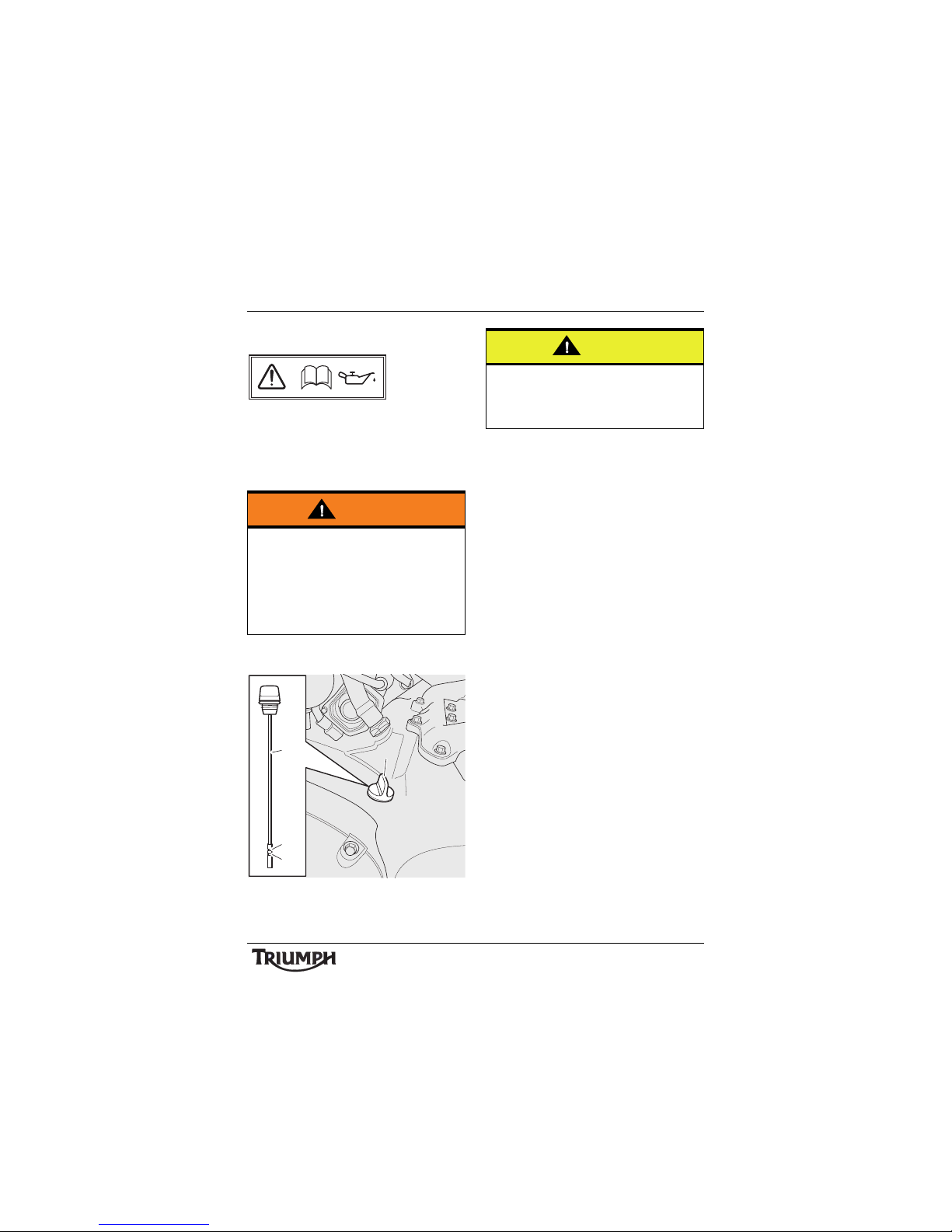
71
Maintenance and Adjustment
Engine Oil
In order for the engine, transmission, and
clutch to function correctly, maintain the
engine oil at the correct level, and change the
oil and oil filter in accordance with scheduled
maintenance requirements.
Oil Level Inspection
1. Filler cap/dipstick
2. Maximum mark
3. Minimum mark
Start the engine and let it idle for five
minutes. Stop the engine and wait three
minutes.
Carefully clean the area around the filler
cap/dipstick before removal.
Remove the filler cap/dipstick from the
crankcase, wipe the dipstick clean and refit
the filler cap/dipstick, screwing it fully home.
Note:
• The actual level is indicated when
the motorcycle is upright, (not on
the side stand) and when the filler
cap/dipstick has been screwed fully
home.
Remove the filler cap/dipstick.
The maximum oil level is indicated by a mark
on the filler cap/dipstick. When the oil level is
correct, the indicated oil level must be
between the maximum and minimum lines
on the dipstick.
If the oil level is too low, add oil a little at a
time until the correct level is reached.
Once the correct level is reached, fit the filler
cap/dipstick.
Warning
Motorcycle operation with insufficient,
deteriorated, or contaminated engine oil
will cause accelerated engine wear and
may result in engine or transmission
seizure. Seizure of the engine or
transmission may lead to sudden loss of
control and an accident.
cbnz
1
2
3
cfdd
1
Caution
Ensure no foreign matter or contamination
enters the engine during an oil change or
top-up. Contamination entering the engine
may lead to engine damage.
Page 72
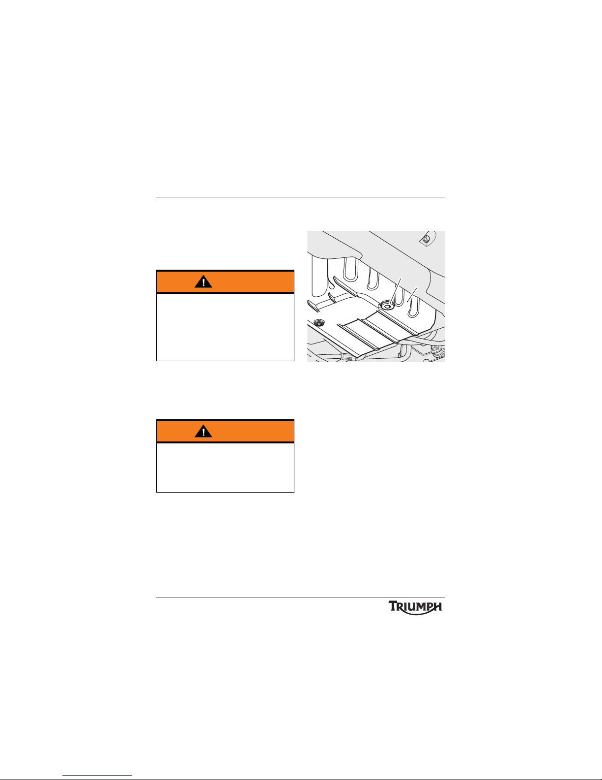
72
Maintenance and Adjustment
Oil and Oil Filter Change
The engine oil and filter must be renewed in
accordance with scheduled maintenance
requirements.
To change the engine oil and filter, follow the
instructions below/overleaf.
Warm up the engine thoroughly then stop
the engine and secure the motorcycle in an
upright position.
Allow the oil to settle for five minutes before
draining.
Place an oil drain pan beneath the engine.
Remove the sump plug from the bottom of
the sump and allow the oil to drain.
Incorporating a new washer, refit the sump
plug, tightening it to 25 Nm.
1. Sump plug
2. Engine sump
Position the oil drain pan beneath the oil filter.
Release the four fixings and remove the
catalytic converter mounting bracket.
Warning
Prolonged or repeated contact with engine
oil can lead to skin dryness, irritation and
dermatitis. In addition, used engine oil
contains harmful contamination that can
lead to skin cancer. Always wear suitable
protective clothing and avoid skin contact
with used oil.
Warning
The oil may be hot to the touch. Avoid
contact with the hot oil by wearing suitable
protective clothing, gloves, eye protection,
etc. Contact with hot oil may cause the skin
to be scalded or burned.
cihn
1
2
Page 73
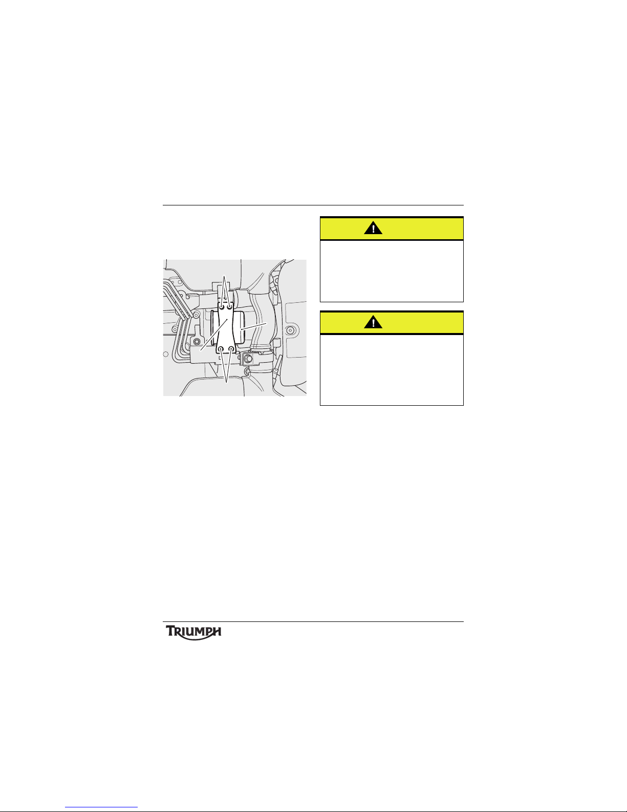
73
Maintenance and Adjustment
Unscrew and remove the oil filter using
Triumph service tool T3880313. Dispose of
the old filter in an environmentally friendly
way.
1. Fixings
2. Catalytic converter mounting
bracket
3. Oil filter
Apply a thin smear of clean engine oil to the
sealing ring of the new oil filter. Fit the oil
filter and tighten to 10 N m .
Refit the catalytic converter mounting bracket
and tighten its fixings to 12 N m .
Fill the engine with a 10W/40 or 10W/50
semi or fully synthetic motorcycle engine oil
that meets specification API SH (or higher)
and JASOMA, such as CastrolPower1
Racing 4T 10W-40 (fully synthetic) engine oil,
sold as Castrol Power RS Racing 4T 10W-40
(fully synthetic) in some countries.
Start the engine and allow it to idle for a
minimum of 30 seconds.
Ensure that the low oil pressure warning light
extinguishes shortly after starting.
Turn off the ignition, check the oil level using
the method previously described, and top up
to between the minimum and maximum
level lines on the dipstick.
cihu
3
1
1
2
Caution
Raising the engine speed above idle,
before the oil reaches all parts of the
engine can cause engine damage or
seizure. Only raise engine speed after
running the engine for 30 seconds to allow
the oil to circulate fully.
Caution
If the engine oil pressure is too low, the low
oil pressure warning light will illuminate. If
this light stays on when the engine is
running, stop the engine immediately and
investigate the cause. Running the engine
with low oil pressure will cause engine
damage.
Page 74
74
Maintenance and Adjustment
Disposal of Used Engine Oil and Oil
Filters
To protect the environment, do not pour oil
on the ground, down sewers or drains, or
into watercourses. Do not place used oil filters
in with general waste. If in doubt, contact
your local authority.
Oil Specification and Grade
Triumph's high performance fuel injected
engines are designed to use 10W/40 or
10W/50 semi or fully synthetic motorcycle
engine oil that meets specification API SH
(or higher) and JASO MA, such as
Castrol Power 1 Racing 4T 10W-40 (fully
synthetic) engine oil, sold as Castrol Power RS
Racing 4T 10W-40 (fully synthetic) in some
countries.
Do not add any chemical additives to the
engine oil. The engine oil also lubricates the
clutch and any additives could cause the
clutch to slip.
Do not use mineral, vegetable, non-detergent
oil, castor based oils or any oil not
conforming to the required specification. The
use of these oils may cause instant, severe
engine damage.
Cooling System
To ensure efficient engine cooling, check the
coolant level each day before riding the
motorcycle, and top up the coolant if the level
is low.
Note:
• A year-round, Hybrid Organic Acid
Technology (known as Hybrid OAT
or HOAT) coolant is installed in the
cooling system when the motorcycle
leaves the factory. It is coloured
green, contains a 50% solution of
ethylene glycol based antifreeze,
and has a freezing point of -35°C
(-31°F).
Page 75
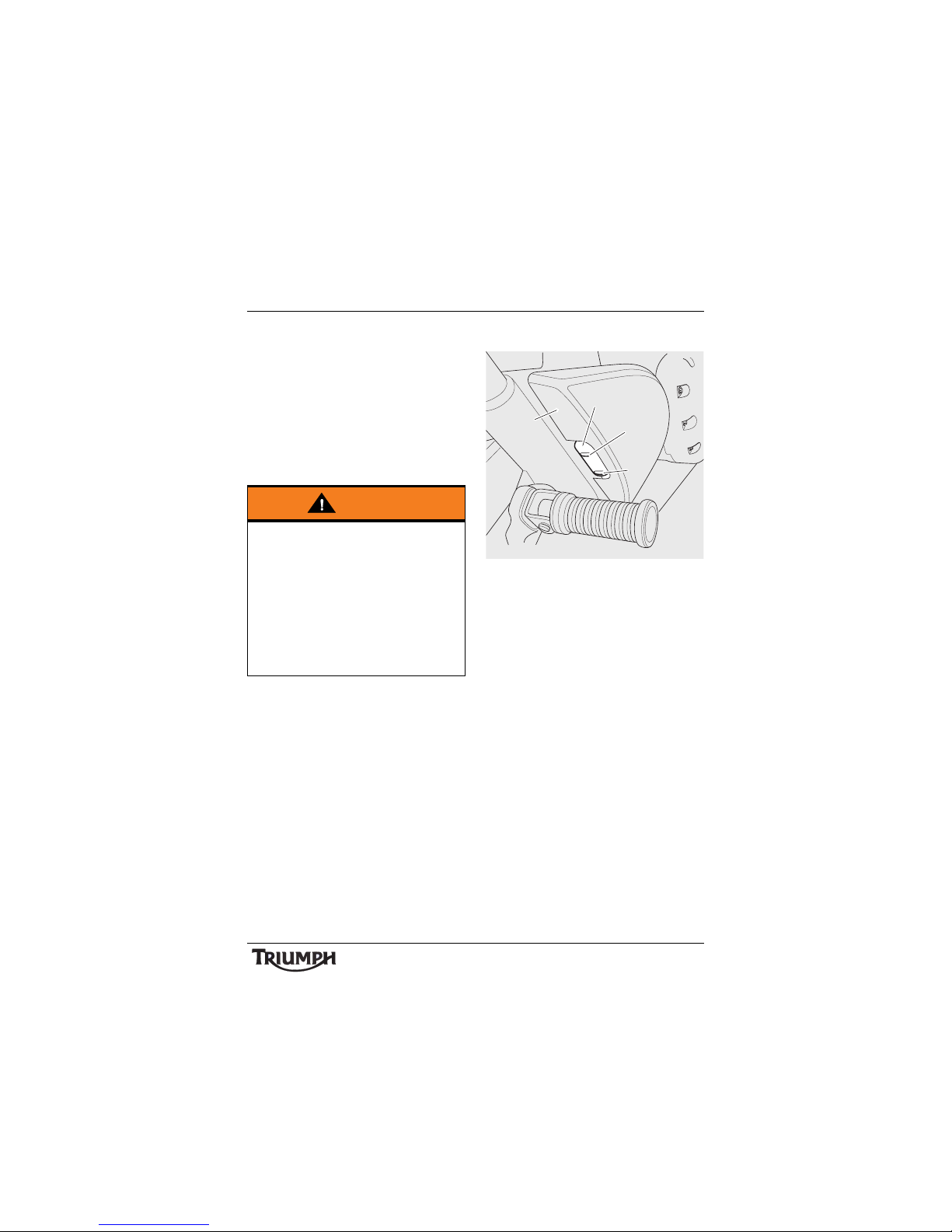
75
Maintenance and Adjustment
Corrosion Inhibitors
To protect the cooling system from corrosion,
the use of corrosion inhibitor chemicals in the
coolant is essential.
If coolant containing a corrosion inhibitor is
not used, the cooling system will accumulate
rust and scale in the water jacket and radiator.
This will block the coolant passages, and
considerably reduce the efficiency of the
cooling system.
Note:
• HD4X Hybrid OAT coolant, as
supplied by Triumph, is pre-mixed
and does not need to be diluted
prior to filling or topping up the
cooling system.
Coolant Level Inspection
1. Final drive belt cover
2. Expansion tank
3. MAX mark
4. MIN mark
Position the motorcycle on level ground and
in an upright position.
The coolant level within the expansion tank
can be inspected without removing any
covers. The expansion tank can be viewed
from the right hand side of the motorcycle,
through a window in the rear of the final
drive belt cover.
Check the coolant level in the expansion
tank. The coolant level must be between the
MAX (upper line) and MI N (lower line)
marks. If the coolant is below the minimum
level, the coolant level must be adjusted.
Warning
HD4X Hybrid OAT coolant contains
corrosion inhibitors and anti-freeze suitable
for aluminium engines and radiators.
Always use the coolant in accordance with
the instructions of the manufacturer.
Coolant that contains anti-freeze and
corrosion inhibitors contains toxic
chemicals that are harmful to the human
body. Never swallow anti-freeze or any of
the motorcycle coolant.
3
4
2
cfbp
1
Page 76
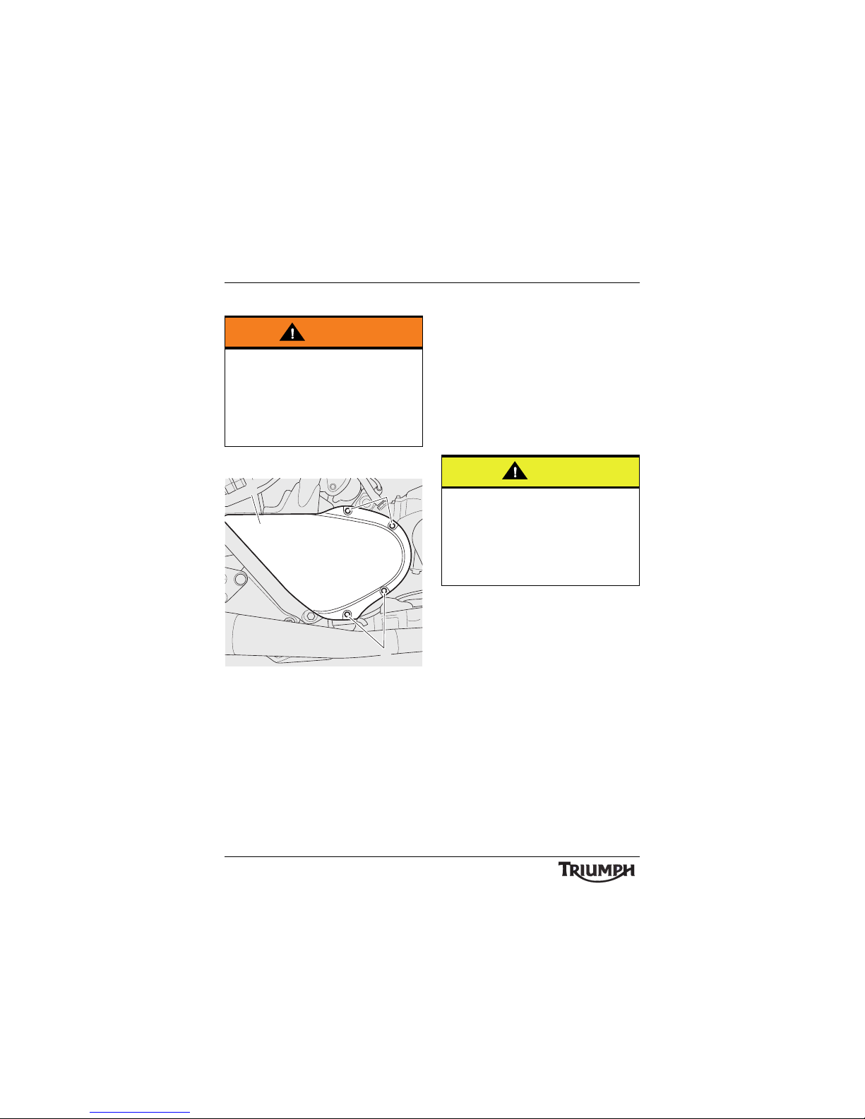
76
Maintenance and Adjustment
Coolant Level Adjustment
Allow the engine to cool.
1. Final drive belt cover
2. Final drive belt cover screws
Remove the final drive belt cover as follows:
Release the four screws from the cover and
remove.
Remove the cap from the expansion tank,
and add coolant mixture through the filler
opening until the level reaches the MAX
mark. Refit the cap.
Note:
• If the coolant level is being checked
because the coolant has overheated,
also check the level in the radiator
and top up if necessary.
• In an emergency, distilled water can
be added to the cooling system.
However, the coolant must then be
drained and replenished with H4DX
Hybrid OAT coolant as soon as
possible.
Refit the final drive belt cover as follows:
Align the cover to the crankcase. Fit and
tighten the four screws to 9Nm.
Coolant Change
Have the coolant changed by an authorised
Triumph dealer in accordance with scheduled
maintenance requirements.
Warning
Do not remove the expansion tank cap or
radiator pressure cap when the engine is
hot. When the engine is hot, the coolant
inside the radiator will be hot and also
under pressure. Contact with this hot,
pressurised coolant will cause scalds and
skin damage.
2
2
f
1
Caution
If hard water is used in the cooling system,
it will cause scale accumulation in the
engine and radiator and considerably
reduce the efficiency of the cooling system.
Reduced cooling system efficiency may
cause the engine to overheat and suffer
severe damage.
Page 77
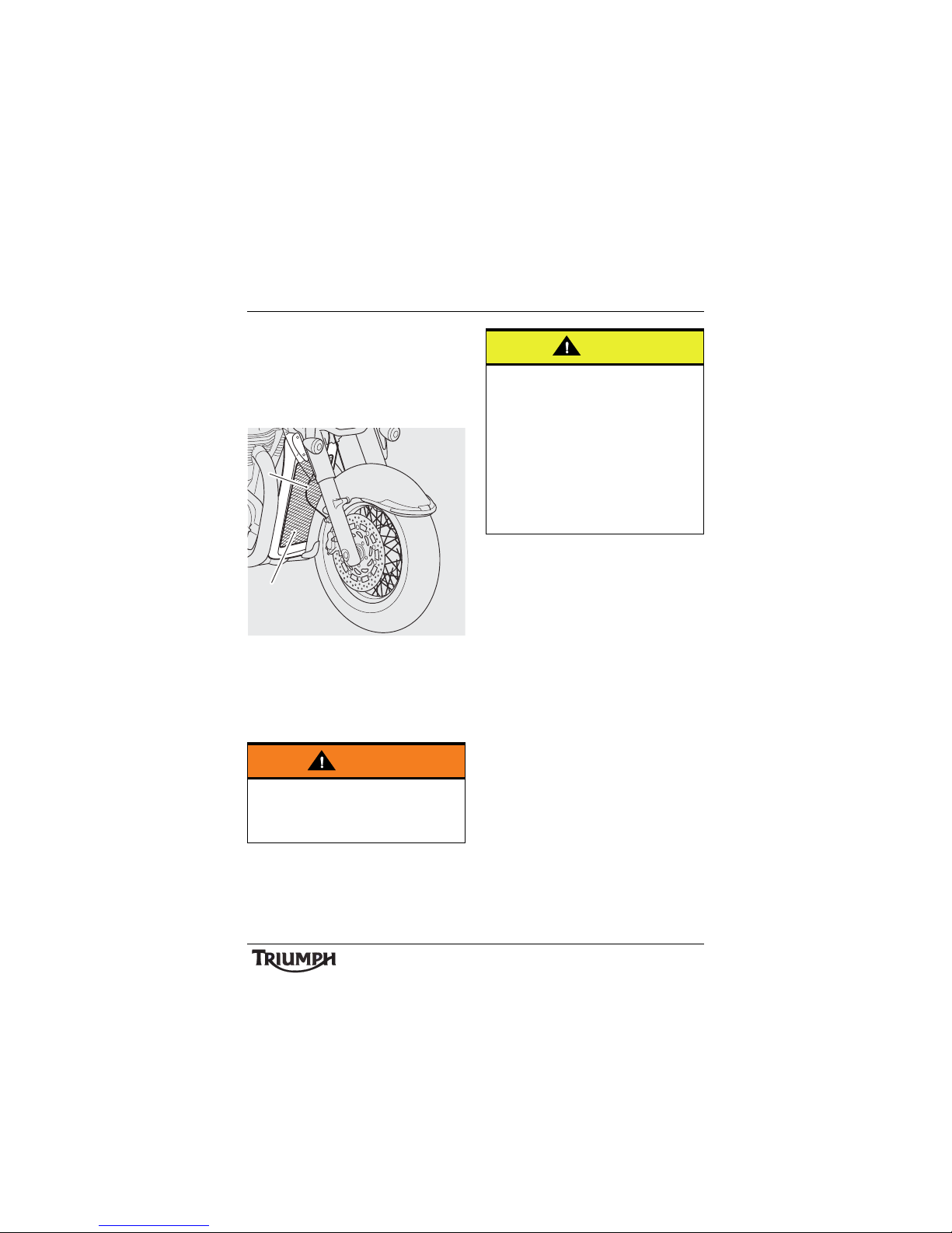
77
Maintenance and Adjustment
Radiator and Hoses
Check the radiator hoses for cracks or
deterioration, and hose clips for tightness in
accordance with scheduled maintenance
requirements. Have your authorised Triumph
dealer replace any defective items.
1. Radiator grille
2. Radiator fins
Check the radiator grille and fins for
obstructions by insects, leaves or mud. Clean
off any obstructions with a stream of lowpressure water.
Warning
The fan operates automatically when the
engine is running. Always keep hands and
clothing away from the fan as contact with
the rotating fan can cause injury.
cihr
2
1
Caution
Using high-pressure water sprays, such as
from a car wash facility or household
pressure washer, can damage the radiator
fins, cause leaks and impair the radiator's
efficiency.
Do not obstruct or deflect airflow through
the radiator by installing unauthorised
accessories, either in front of the radiator or
behind the cooling fan. Interference with
the radiator airflow can cause overheating,
potentially resulting in engine damage.
Page 78
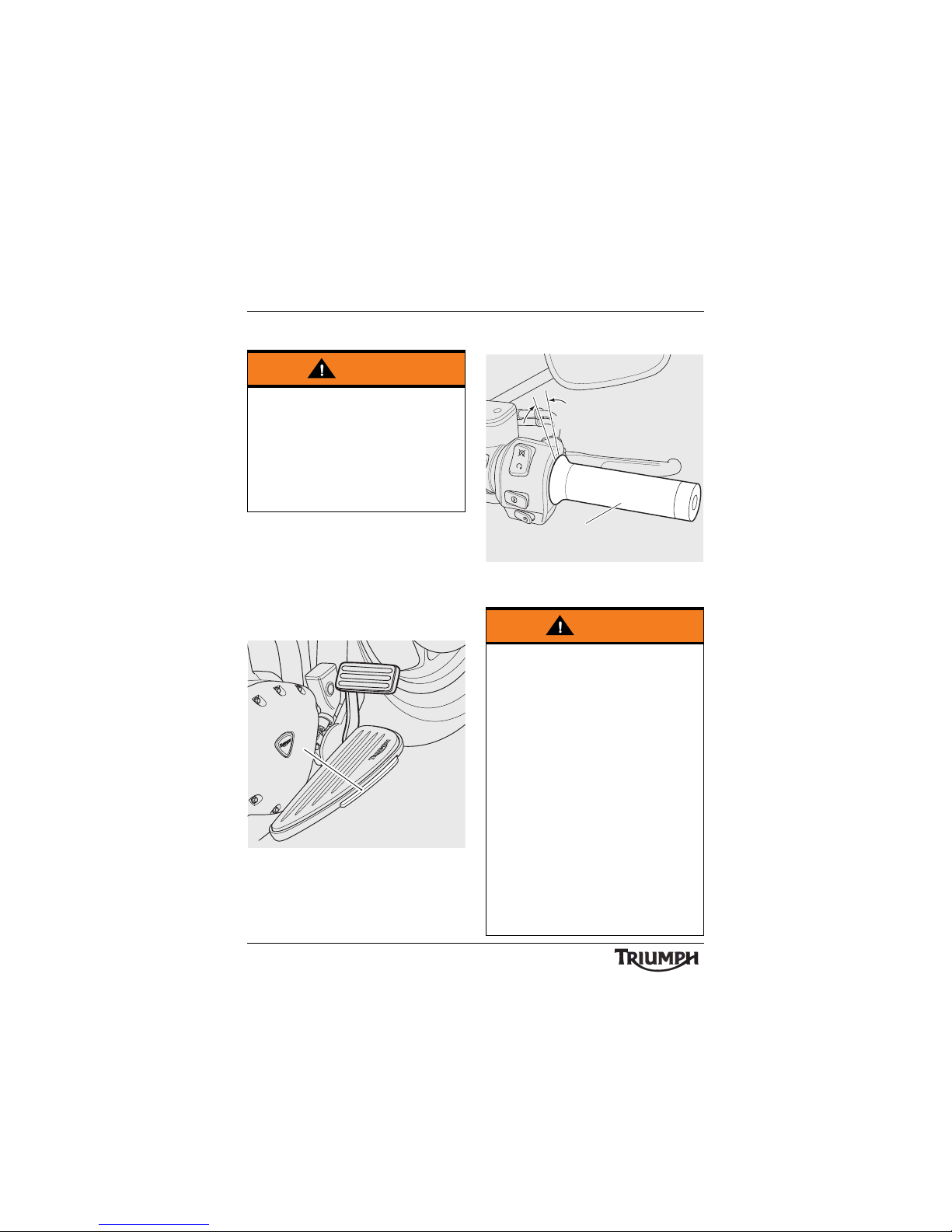
78
Maintenance and Adjustment
Bank Angle Indicators
Bank angle indicators are located on the
outer edge of the rider's footboards.
Regularly check the bank angle indicators for
wear on the outer edge.
Replace the bank angle indicators when the
bank angle indicator is worn before the
footboard starts to get damaged.
1. Bank angle indicator
Throttle Control
1. Throttle grip
2. Correct setting 2 - 3 mm
Warning
Use of a motorcycle with bank angle
indicators worn beyond the maximum
limit (as described below) will allow the
motorcycle to be banked to an unsafe
angle.
Banking to an unsafe angle may cause
instability, loss of motorcycle control and
an accident.
cihf_1
1
Warning
The throttle grip controls the throttle valves
in the throttle bodies. If the throttle cables
are incorrectly adjusted, either too tight or
too loose, the throttle may be difficult to
control and performance will be adversely
affected.
Check the throttle grip free play in
accordance with scheduled maintenance
requirements and make adjustments as
necessary.
Always be alert for changes in the 'feel' of
the throttle and have the throttle system
checked by an authorised Triumph dealer
if any changes are detected. Changes can
be due to wear in the mechanism, which
could lead to a sticking throttle.
An incorrectly adjusted, sticking or stuck
throttle will lead to loss of motorcycle
control and an accident.
cfcd
1
2
Page 79
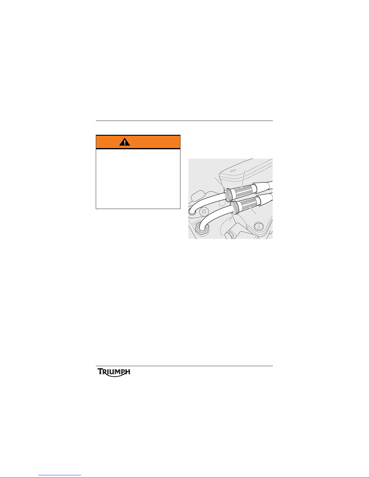
79
Maintenance and Adjustment
Inspection
Check that the throttle opens smoothly,
without undue force and that it closes without
sticking. Have your authorised Triumph
dealer check the throttle system if a problem
is detected or any doubt exists.
Check that there is 2 - 3 mm of throttle grip
free play when lightly turning the throttle grip
back and forth.
If there is an incorrect amount of free play,
Triumph recommends that you have
adjustments made by your authorised
Triumph dealer. However, in an emergency,
throttle adjustment may be made as follows:
1. Opening cable adjuster
2. Opening cable adjuster lock nut
3. Closing cable adjuster
4. Closing cable adjuster lock nut
Release the lock nut on the 'opening' cable
adjuster.
Warning
Use of the motorcycle with incorrectly
adjusted, incorrectly routed, sticking or
damaged throttle cables will interfere with
the throttle function resulting in loss of
motorcycle control and an accident.
To avoid incorrect adjustment, incorrect
routing, or continued use of a sticking or
damaged throttle, always have your
throttle checked and adjusted by your
authorised Triumph dealer.
1
2
4
3
Page 80
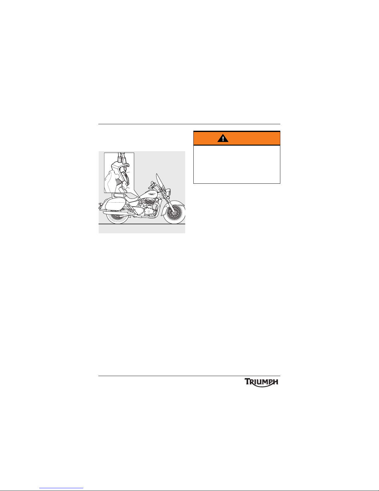
80
Maintenance and Adjustment
Rotate the 'opening' cable adjuster at the
twist grip end to give 2 - 3 mm of play at the
twist grip. Tighten the lock nut.
1. Closing cable
2. Throttle cam
With the throttle fully closed, ensure that
there is 2 - 3 mm of free play in the 'closing'
cable at the throttle cam attached to the
throttle bodies. This is accessible from the
right hand side of the motorcycle, below the
fuel tank (it is not necessary to remove the
fuel tank). If necessary, adjust in the same
way as the 'opening' cable (at the twist grip
end) until 2 - 3 mm of play is present.
Check that the throttle opens smoothly,
without undue force and that it closes without
sticking.
Ride carefully to your nearest authorised
Triumph dealer and have them check the
throttle system thoroughly before riding
again.
2
1
Warning
Ensure that all the adjuster lock nuts of
both cables are tightened, as a loose lock
nut could result in a sticking throttle.
An incorrectly adjusted, sticking or stuck
throttle can lead to loss of motorcycle
control and an accident.
Page 81
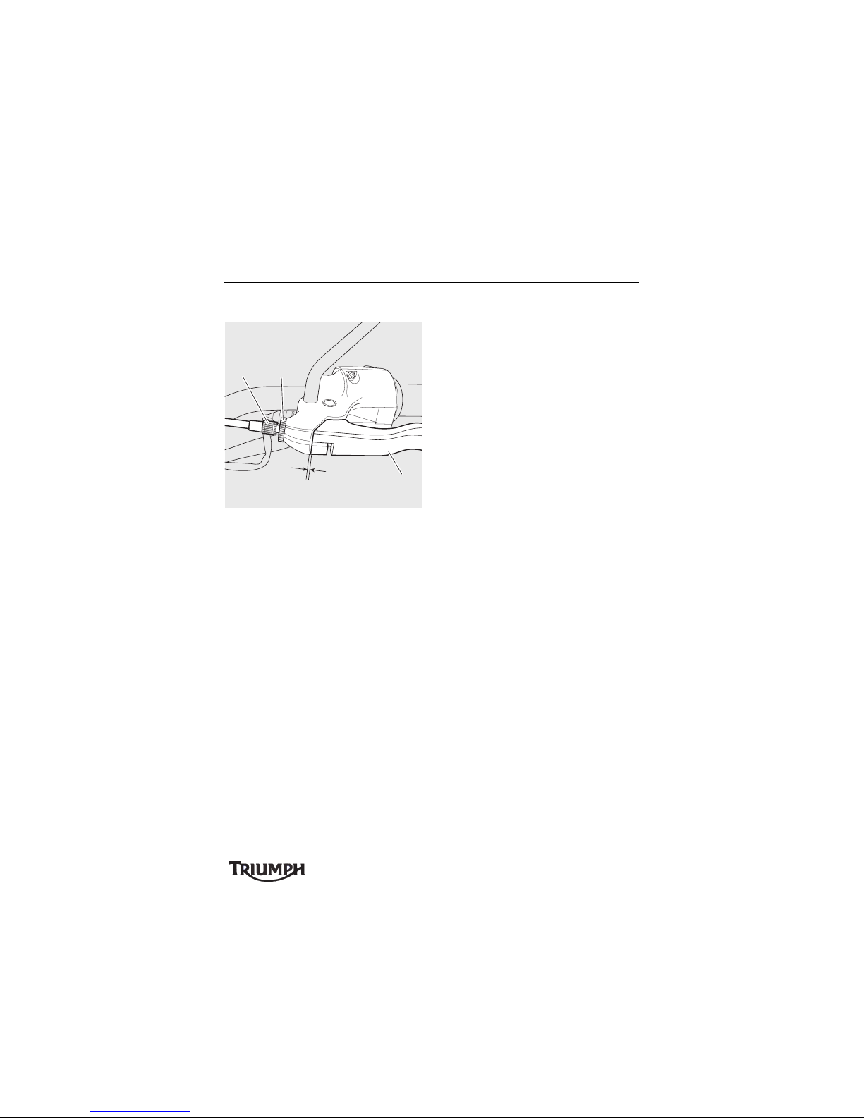
81
Maintenance and Adjustment
Clutch
1. C l u tc h l ev er
2. Correct setting 1 - 2 mm
3. Knurled lock nut
4. Adjuster sleeve
The motorcycle is equipped with a cableoperated clutch.
If the clutch lever has excessive free play, the
clutch may not disengage fully. This will cause
difficulty in changing gear and selecting
neutral. This may cause the engine to stall
and make the motorcycle difficult to control.
Conversely, if the clutch lever has insufficient
free play the clutch may not engage fully,
causing the clutch to slip, which will reduce
performance and cause premature clutch
wear.
Clutch lever free play must be checked in
accordance with scheduled maintenance
requirements.
Inspection
Check that there is 1 - 2 mm clutch lever free
play at the lever.
If there is an incorrect amount of free play,
adjustments must be made.
Adjustment
Loosen the knurled lock nut at the lever end
of the clutch cable and turn the adjuster
sleeve until the correct amount of clutch lever
free play is achieved.
Tighten the knurled lock nut against the
clutch lever assembly.
If correct adjustment cannot be made using
the lever adjuster, use the cable adjuster at
the middle of the cable, located to the right of
the radiator, adjacent to the frame.
Loosen the adjuster lock nut.
Turn the outer cable adjuster to give
1 -2 mm of free play at the clutch lever.
Tighten the lock nut.
4
21
3
Page 82
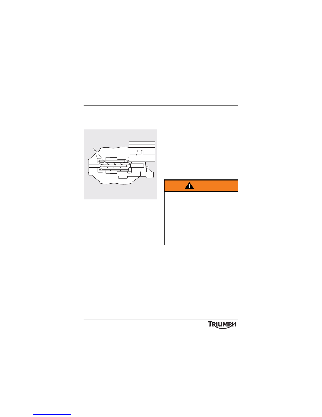
82
Maintenance and Adjustment
Brakes
Brake Wear Inspection
1. Brake pads
2. Minimum thickness line
Brake pads must be inspected in accordance
with scheduled maintenance requirements
and replaced if worn to, or beyond the
minimum service thickness.
If the lining thickness of any pad (front or rear
brakes) is less than 1.5 mm (0.06 in), that is, if
the pad has worn down to the bottom of the
grooves, replace all the pads on the wheel.
Breaking-in New Brake Pads and
Discs
After replacement brake discs and/or pads
have been fitted to the motorcycle, we
recommend a period of careful breaking-in
that will optimise the performance and
longevity of the discs and pads. The
recommended distance for breaking-in new
pads and discs is 200 miles (300 km).
After fitting new brake discs and/or pads
avoid extreme braking, ride with caution and
allow for greater braking distances during the
breaking-in period.
cbmz
1
2
Warning
Brake pads must always be replaced as a
wheel set. At the front, where two calipers
are fitted on the same wheel, replace all
the brake pads in both calipers.
Replacing individual pads will reduce
braking efficiency and may cause an
accident.
After replacement brake pads have been
fitted, ride with extreme caution until the
new pads have 'broken in'.
Page 83
83
Maintenance and Adjustment
Brake Pad Wear Compensation
Disc and brake pad wear is automatically
compensated for and has no effect on the
brake lever or pedal action. There are no
parts that require adjustment on the front
and rear brakes.
Disc Brake Fluid
Inspect the level of brake fluid in both
reservoirs and change the brake fluid in
accordance with scheduled maintenance
requirements. Use only DOT 4 fluid as
recommended in the Specification section.
The brake fluid must also be changed if it
becomes, or is suspected of having become
contaminated with moisture or any other
contaminants.
Warning
If the brake lever or pedal feels soft when it
is applied, or if the lever/pedal travel
becomes excessive, there may be air in the
brake pipes and hoses or the brakes may
be defective.
It is dangerous to operate the motorcycle
under such conditions and your authorised
Triumph dealer must rectify the fault
before riding.
Riding with defective brakes may lead to
loss of motorcycle control and an accident.
Warning
Brake fluid is hygroscopic which means it
will absorb moisture from the air.
Any absorbed moisture will greatly reduce
the boiling point of the brake fluid causing
a reduction in braking efficiency.
Because of this, always replace brake fluid
in accordance with scheduled maintenance
requirements.
Always use new brake fluid from a sealed
container and never use fluid from an
unsealed container or from one which has
been previously opened.
Do not mix different brands or grades of
brake fluid.
Check for fluid leakage around brake
fittings, seals and joints and also check the
brake hoses for splits, deterioration and
damage.
Always rectify any faults before riding.
Failure to observe and act upon any of
these items may cause a dangerous riding
condition leading to loss of control and an
accident.
Page 84

84
Maintenance and Adjustment
Note:
• A special tool is required to bleed
the ABS braking system. Contact
your authorised Triumph dealer
when the brake fluid needs
renewing or the hydraulic system
requires maintenance.
Brake Fluid Level Inspection and
Adjustment
Front Brakes
1. Front brake fluid reservoir, lower
level line
2. Upper level line
3. Fluid level window
The brake fluid level in the reservoirs must be
kept between the upper and lower level lines
(reservoir held horizontal).
To inspect the front brake fluid level, check
the level of fluid visible in the window at the
front of the reservoir body.
Release the screws and remove the cover
noting the position of the diaphragm inside.
Fill the reservoir to the upper level line using
new DOT 4 fluid from a sealed container.
Refit the reservoir cover ensuring that the
diaphragm seal is correctly fitted. Tighten the
screws to 2Nm.
Warning
If the ABS is not functioning, the brake
system will continue to function as a
standard non-ABS braking system. In this
situation, braking too hard will cause the
wheels to lock resulting in loss of control
and an accident.
Reduce speed and do not continue to ride
for longer than is necessary with the
indicator light illuminated. Contact an
authorised Triumph dealer as soon as
possible to have the fault checked and
rectified.
3
2
1
dga
Page 85
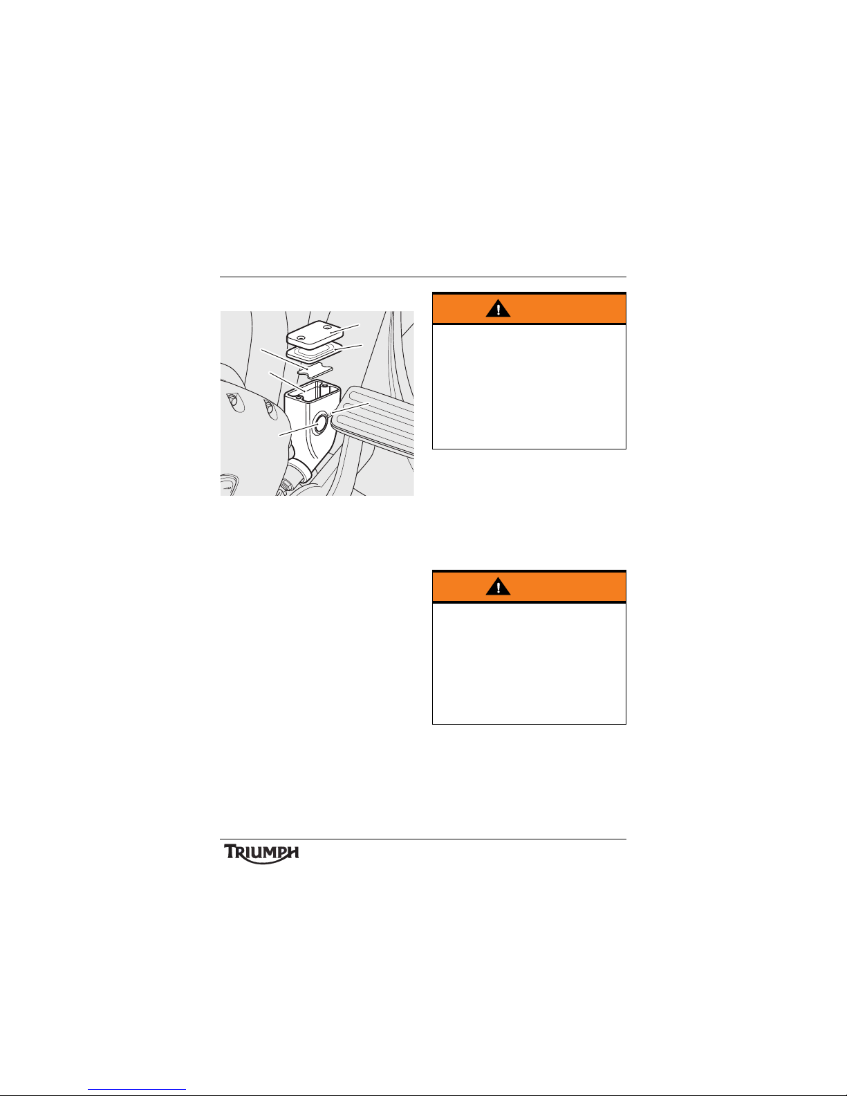
85
Maintenance and Adjustment
Rear Brake
1. Rear brake fluid reservoir, fluid level
window
2. Lower level line
3. Upper level line
4. Float
5. Diaphragm
6. Cover
To inspect the rear brake fluid level, check the
level of fluid visible in the window at the side
of the reservoir body.
To adjust the rear brake fluid level, release the
fixings and remove the cover noting the
position of the diaphragm and the float
inside.
Fill the reservoir to the upper level line using
DOT 4 fluid from a sealed container, with the
motorcycle supported in an upright position.
Refit the float into the reservoir then the
reservoir cover, ensuring that the diaphragm
seal is correctly positioned between the cap
and reservoir body. Tighten the fixings to
2Nm.
cihs
1
3
2
4
5
6
Warning
After topping up the brake fluid in the rear
brake fluid reservoir, ensure the float is
installed into the reservoir.
Failure to install the float may result in
aeration of the brake fluid in the reservoir.
Riding with brake fluid in this condition
may reduce brake performance potentially
leading to loss of motorcycle control and
an accident.
Warning
If there has been an appreciable drop in
the level of the fluid in either fluid
reservoir, consult your authorised Triumph
dealer for advice before riding. Riding with
depleted brake fluid levels, or with a brake
fluid leak is dangerous and will cause
reduced brake performance potentially
leading to loss of motorcycle control and
an accident.
Page 86
86
Maintenance and Adjustment
Brake Light Switches
The brake light is activated independently by
either the front or rear brake. If, with the
ignition in the ON position, the brake light
does not work when the front brake lever is
pulled or the rear brake pedal is pressed,
have your authorised Triumph dealer
investigate and rectify the fault.
Steering/Wheel Bearings
Steering Inspection
Lubricate and inspect the condition of the
steering (headstock) bearings in accordance
with scheduled maintenance requirements.
Note:
• Always inspect the wheel bearings at
the same time as the steering
bearings.
Warning
Riding the motorcycle with defective brake
lights is illegal and dangerous.
An accident causing injury to the rider and
other road users may result from use of a
motorcycle with defective brake lights.
Warning
To prevent risk of injury from the
motorcycle falling during the inspection,
ensure that the motorcycle is stabilised and
secured on a suitable support. Do not
exert extreme force against each wheel or
rock each wheel vigorously as this may
cause the motorcycle to become unstable
and cause injury by falling from its support.
Ensure that the position of the support
block will not cause damage to the sump.
Page 87
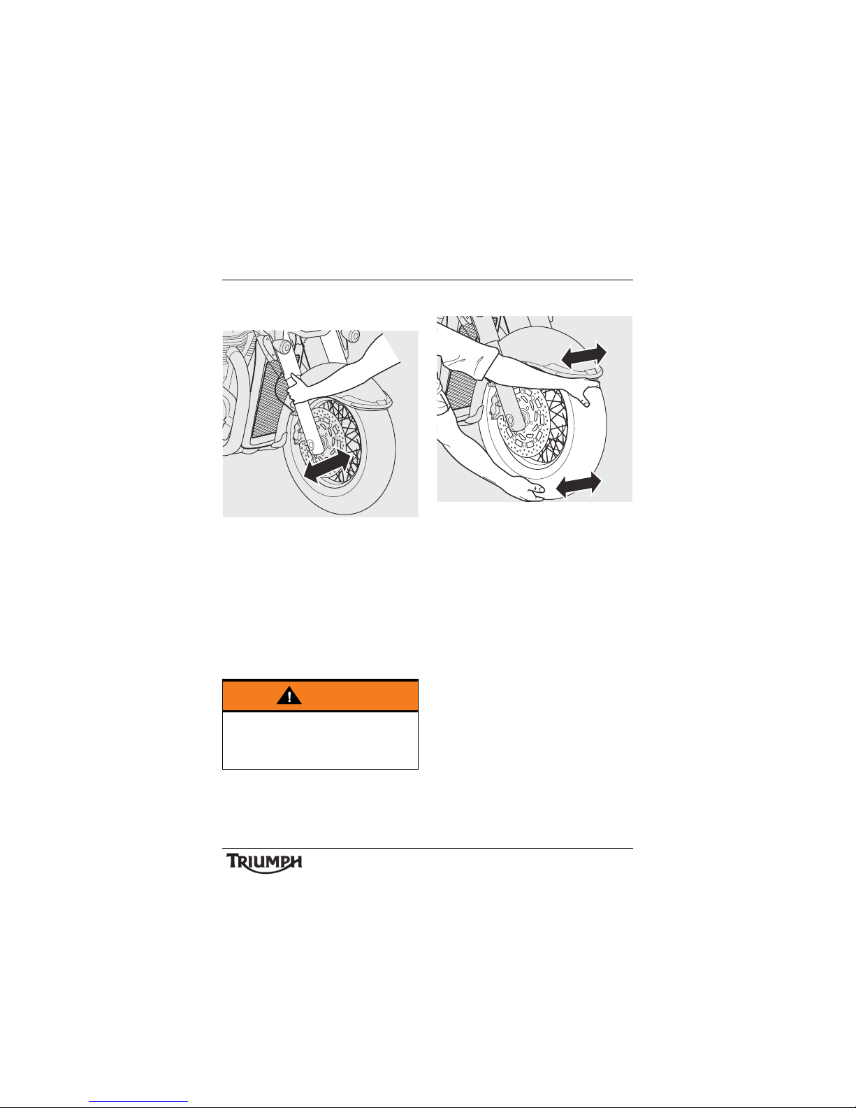
87
Maintenance and Adjustment
Inspecting the Steering (Headstock)
Bearings for Free Play
Position the motorcycle on level ground, in an
upright position.
Raise the front wheel above the ground and
support the motorcycle.
Standing at the front of the motorcycle, hold
the lower end of the front forks and try to
move them forward and backward.
If any free play can be detected in the
steering (headstock) bearings, ask your
authorised Triumph dealer to inspect and
rectify any faults before riding.
Remove the support and place the
motorcycle on the side stand.
Wheel Bearings Inspection
If the wheel bearings in the front or rear
wheel allow play in the wheel hub, are noisy,
or if the wheel does not turn smoothly, have
your authorised Triumph dealer inspect the
wheel bearings.
The wheel bearings must be inspected at the
intervals specified in the scheduled
maintenance chart.
Position the motorcycle on level ground, in an
upright position.
Raise the front wheel above the ground and
support the motorcycle.
Standing at the side of the motorcycle, gently
rock the top of the front wheel from side to
side.
If any free play can be detected, ask your
authorised Triumph dealer to inspect and
rectify any faults before riding.
Reposition the lifting device and repeat the
procedure for the rear wheel.
Warning
Riding the motorcycle with incorrectly
adjusted or defective steering (headstock)
bearings is dangerous and may cause loss
of motorcycle control and an accident.
cihr_1
cihr_2
Page 88
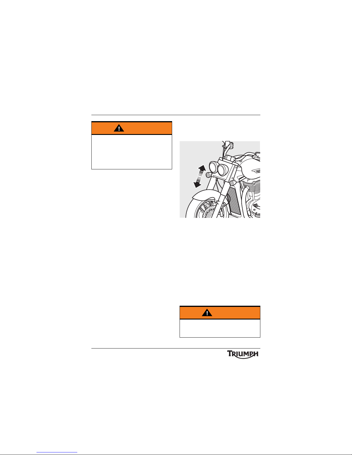
88
Maintenance and Adjustment
Remove the support and place the
motorcycle on the side stand.
Front Suspension
Front Fork Inspection
Thunderbird Commander Shown
Examine each fork for any sign of damage,
scratching of the slider surface, or for oil
leaks.
If any damage or leakage is found, consult an
authorised Triumph dealer.
To check that the forks operate smoothly:
• Position the motorcycle on level ground.
• While holding the handlebars and
applying the front brake, pump the forks
up and down several times.
• If roughness or excessive stiffness is
detected, consult your authorised
Trium p h d e a l e r.
Warning
Operation with worn or damaged front or
rear wheel bearings is dangerous and may
cause impaired handling and instability
leading to an accident. If in doubt, have the
motorcycle inspected by an authorised
Triumph dealer before riding.
Warning
Riding the motorcycle with defective or
damaged suspension is dangerous and
may lead to loss of control and an accident.
cihi
Page 89
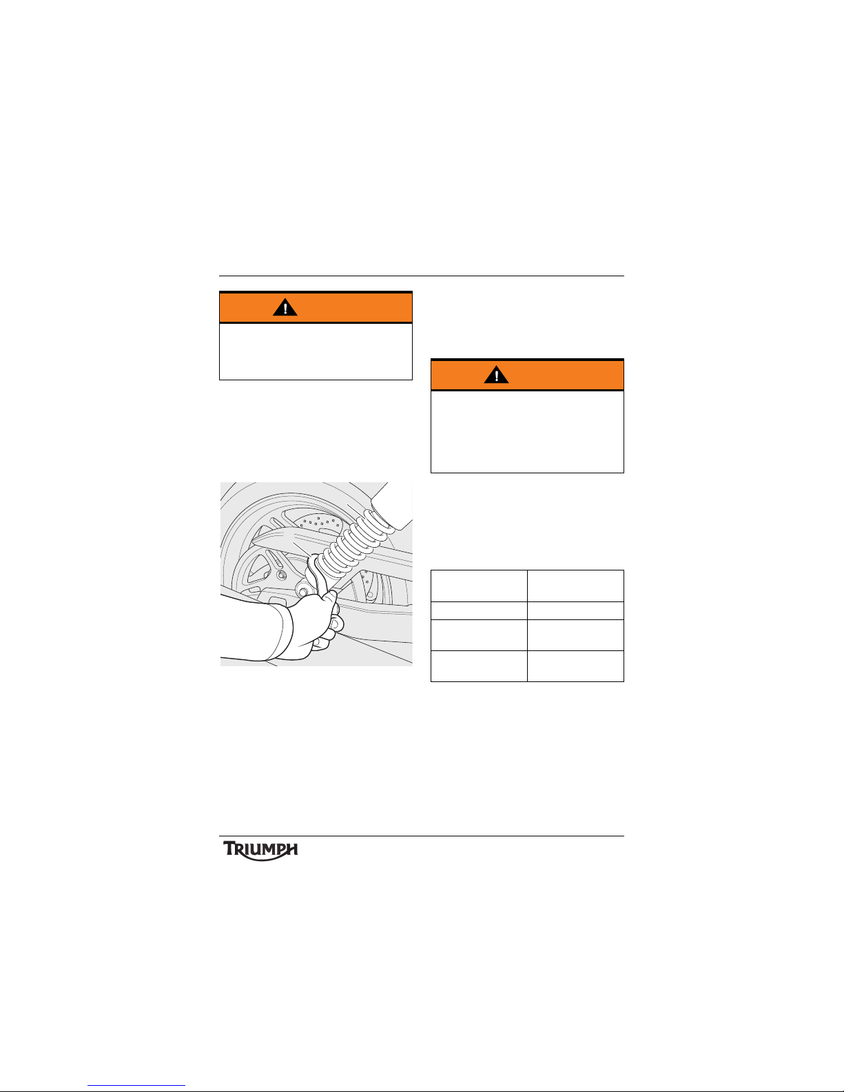
89
Maintenance and Adjustment
Suspension Adjustment
Front Suspension
The front suspension is factory set and is not
adjustable.
Rear Suspension
1. Rear suspension unit
2. Adjustment tool
The rear suspension is adjustable for pre-load
only.
For Thunderbird LT only: Remove the
panniers (see page 44).
To change the rear suspension spring preload setting, insert the adjustment tool
located in the base of the pillion seat into the
hole provided in the adjuster ring.
Turn the adjuster ring clockwise to increase
spring pre-load, and anti-clockwise to
decrease spring pre-load. When delivered
from the factory, the pre-load adjuster will be
set at position 1.
Suggested Suspension Settings
Adjuster settings are counted from position
one with position one being with the adjuster
turned fully anti-clockwise. There are five
positions in total. Position 1 gives the
minimum amount of spring pre-load.
Note:
• The details given in the table are
only a guide. Setting requirements
may vary for rider and passenger
weight and personal preferences.
For Thunderbird LT only: Refit the panniers
(see page 45).
Warning
Never attempt to dismantle any part of the
suspension units, as all units contain
pressurised oil. Skin and eye damage can
result from contact with the pressurised oil.
1
cfgr
2
Warning
Ensure that the adjusters are set to the
same setting on both rear suspension
units. Settings that vary from left to right
may affect handling and stability resulting
in loss of motorcycle control and an
accident.
Riding
Condition
Suspension
Preload Setting
Rider only Position 1
Rider and
passenger
Posi tion 5
Rider, passenger
and luggage
Posi tion 5
Page 90
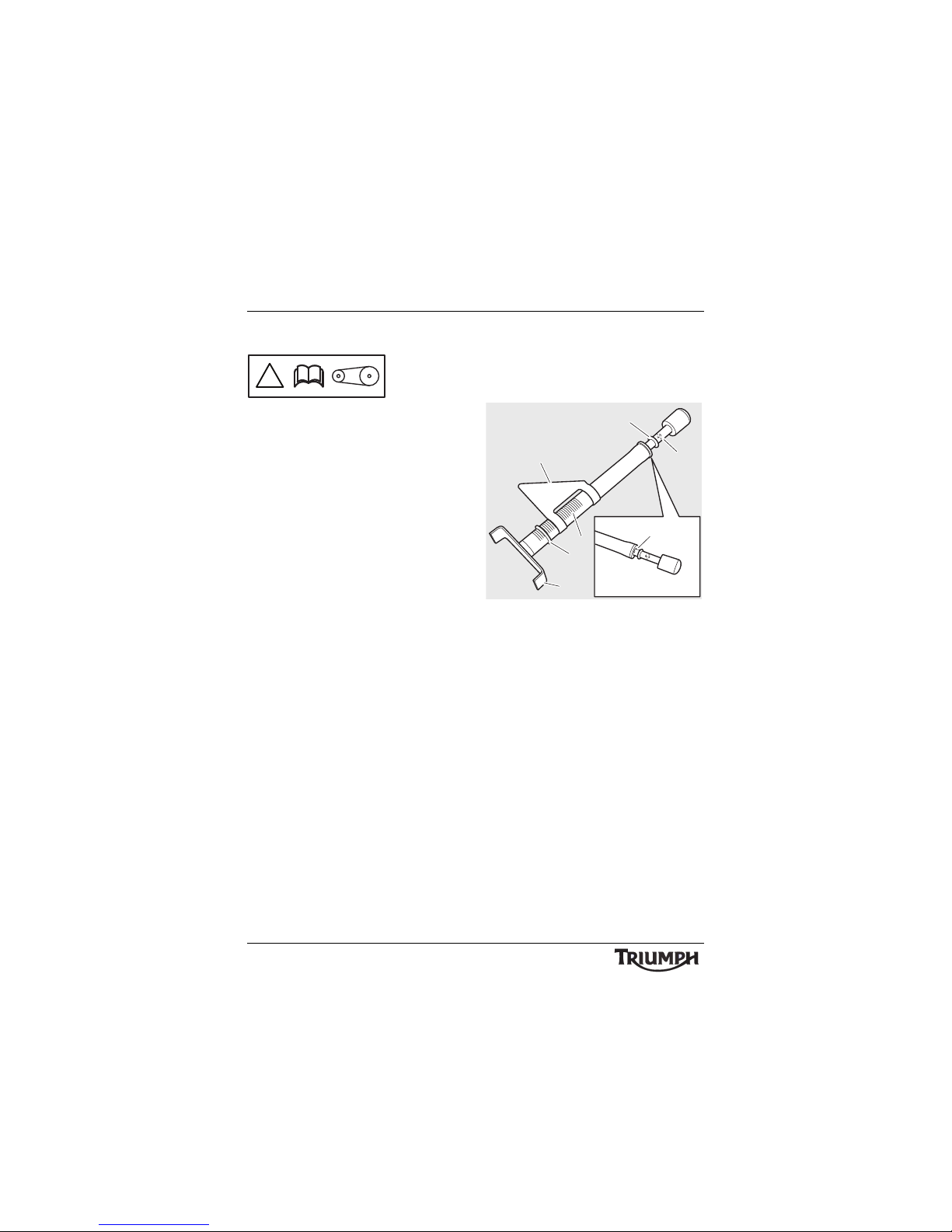
90
Maintenance and Adjustment
Final Drive Belt
For safety and to prevent excessive wear the
drive belt must be checked, adjusted and
renewed in accordance with scheduled
maintenance requirements. Checking and
adjustment must be carried out more
frequently for extreme conditions such as
salty or heavily gritted roads.
If the drive belt is badly worn or incorrectly
adjusted (either too loose or too tight) the
belt could jump off the drive belt pulleys or
break. Therefore, always replace worn or
damaged drive belts using genuine Triumph
parts supplied by an authorised Triumph
dealer. The drive belt requires no lubrication.
Final Drive Belt Tension Inspection
Drive belt tension must be measured using
Triumph service tool T3880126, which is
available from your Triumph dealer.
Service Tool T3880126
1. Load scale - 4.5 kgf (10 lbf) mark
2. O-ring
3. Deflection slider
4. Deflection scale (0.5 mm (0.020 in)
increments)
5. O-ring
6. Belt cradle
7. Load scale (zero position)
Drive belt tension can be measured with the
motorcycle on the side stand, or if available,
on support stand T3880803 (available from
your Triumph dealer). The method of
measurement and adjustment is identical, but
the belt tension specification for each method
is different.
Drive belt tension must be measured with the
drive belt cold (at ambient temperature).
!
5
4
7
1
3
2
6
cfhc
Page 91
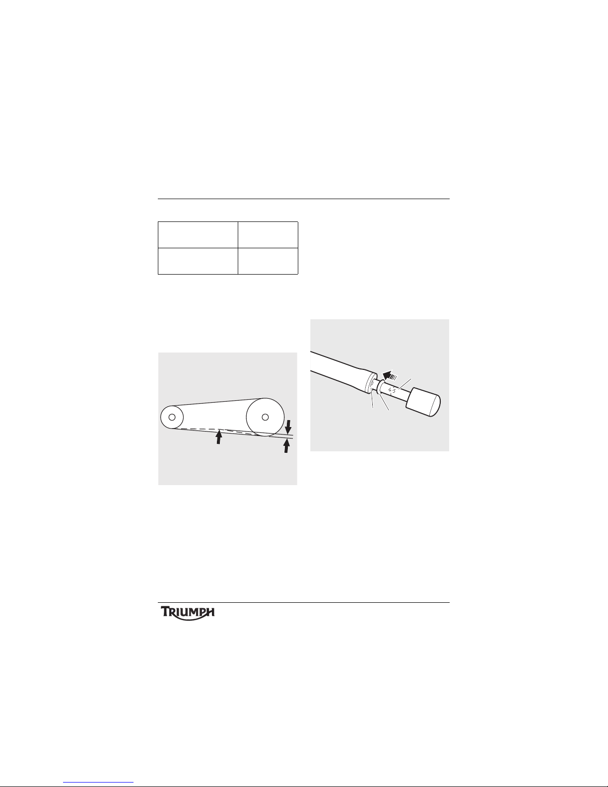
91
Maintenance and Adjustment
Drive Belt Tension Specification
Drive belt tension is measured by applying a
4.5 kilogram-force (kgf) (10 pound-force (lbf))
load to the plunger on service tool T3880126,
once it has been positioned to the lower run
of drive belt; this load then deflects the belt.
The belt deflection can then be measured
using a scale on the tool.
1. 4.5 kilogram-force (10 pound-force)
applied to belt
2. Amount of deflection
Measure the drive belt tension as follows:
Note:
• During the following procedure the
exhaust is shown removed for
clarity, however it is not necessary
to remove the exhaust to check or
adjust the drive belt tension.
• Slide the small O-ring on tool T3880126
along the tool to the zero position on the
load scale.
1. L o a d s ca le
2. O-ring
3. Zero position
Motorcycle on
sidestand
5.5 to 7.0 mm
(0.20 to 0.27 in)
Motorcycle on support
stand T3880803
7.5 to 9.0 mm
(0.30 to 0.35 in)
1
2
1
2
hc
3
Page 92
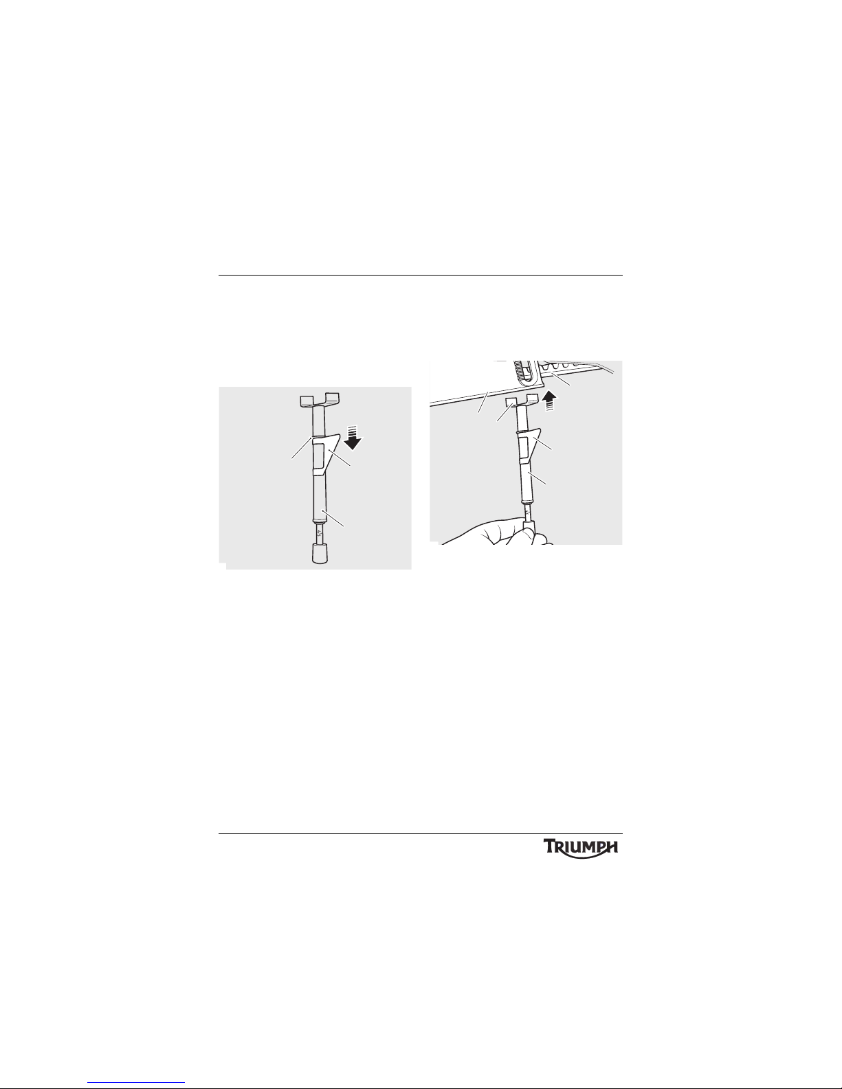
92
Maintenance and Adjustment
• Push the deflection slider and its O-ring
down the tool, so that it will not touch the
drive belt lower cover when the tool is
positioned to the drive belt. Rotate the
deflection slider so that it will contact the
lower belt cover when the tool is
positioned to the motorcycle.
1. Service tool T3880126
2. Deflection slider
3. O-ring
• Gently position the tool’s belt cradle to
the centre of the lower drive belt run,
ensuring the deflection slider on the tool
body is NOT in contact with the drive
belt cover at this stage.
1. Drive belt
2. Service tool T3880126
3. Belt cradle
4. Drive belt lower cover
5. Deflection slider
1
2
3
4
1
3
2
5
Page 93
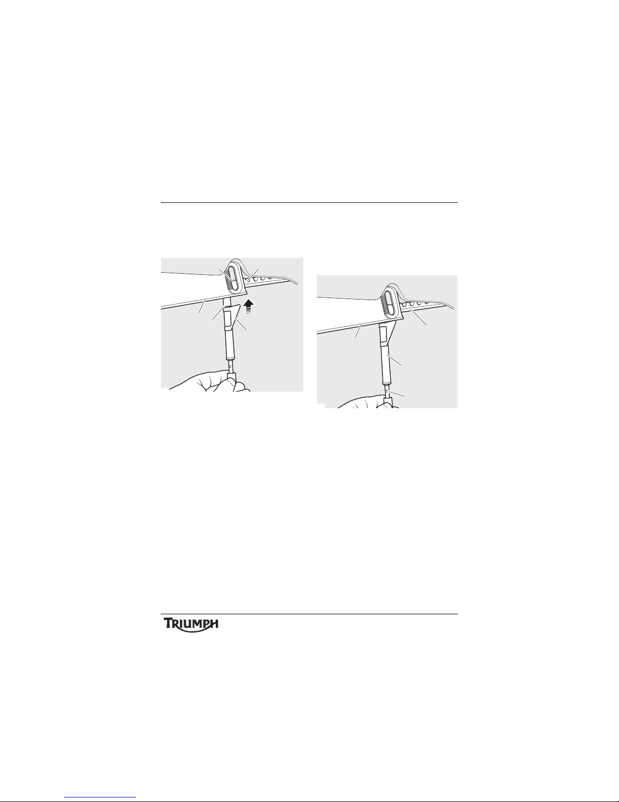
93
Maintenance and Adjustment
• Taking care not to deflect the belt, slide
the deflection slider and its O-ring
upwards until the slider just touches the
belt cover.
1. Drive belt
2. Belt cradle
3. Deflection slider
4. O-ring
5. Drive belt lower cover
• Apply force to the belt tension gauge in
an upwards direction, until the 4.5 kgf
(10 lbf) mark on the load scale is
reached. The deflection slider must
remain stationary against the belt cover
while the force is applied.
1. Drive belt
2. Scale
3. Drive belt lower cover
4. Load scale
5
2
1
3
4
cfhd
3
1
2
4
cfhe
Page 94
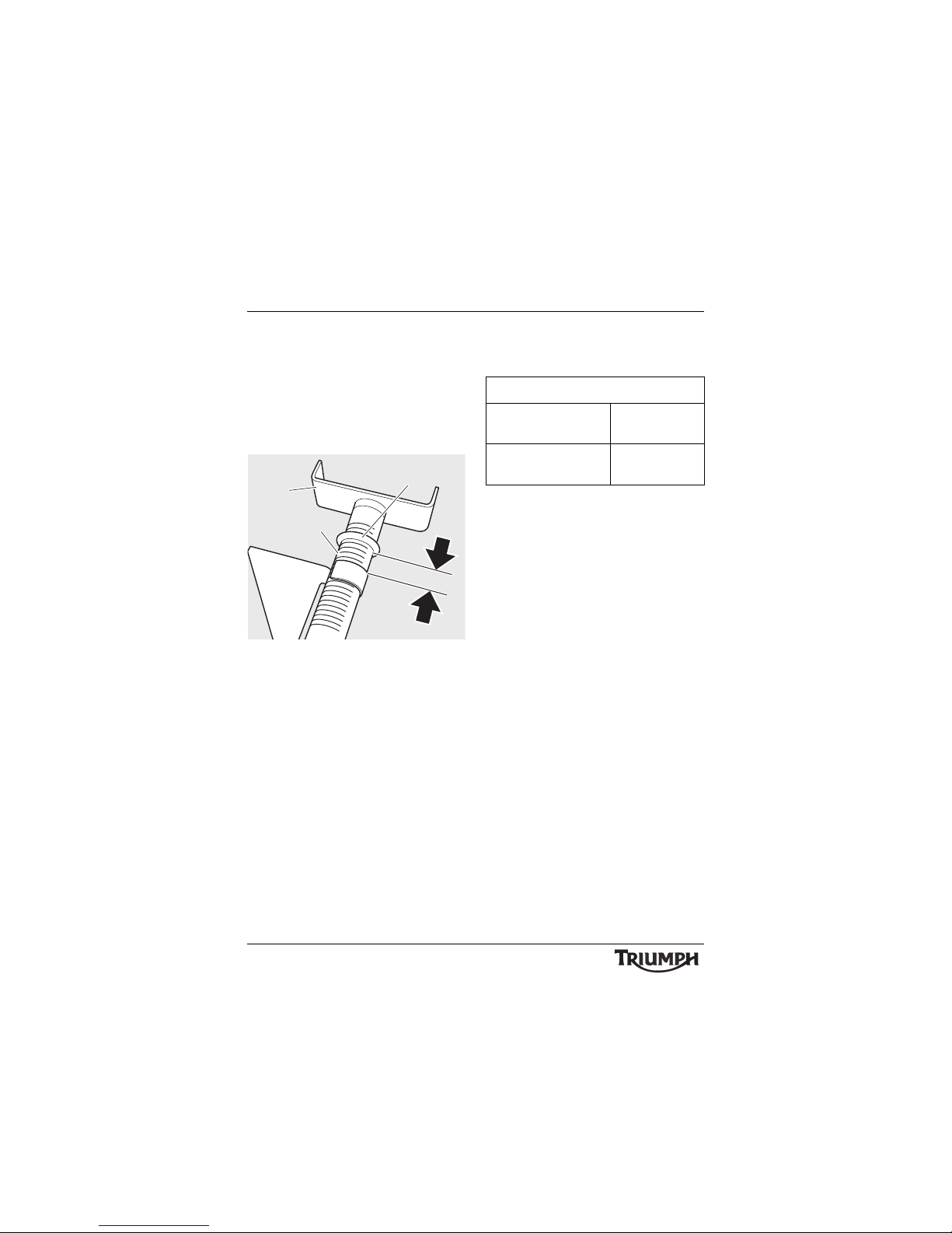
94
Maintenance and Adjustment
• Remove the tool, taking care not to
move the O-ring or deflection slider, and
read the belt deflection on the scale on
the tool. The belt deflection is the gap
between the top of deflection slider and
the lower edge of the O-ring. The
increments on the scale are 0.5 mm
(0.020 in) apart.
1. B e l t d ef le ct io n
2. Scale
3. Deflection slider
4. O-ring
• Repeat the measurement at several
points around the drive belt to locate its
tightest point. Always adjust drive belt
tension at the tightest point in the drive
belt.
If the drive belt deflection is outside the limits
given below, the drive belt must be adjusted
(see page 95).
1
2
3
4
Drive Belt Tension Specification
Motorcycle on
sidestand
5.5 to 7.0 mm
(0.20 to 0.27 in)
Motorcycle on Support
stand T3880803
7.5 to 9.0 mm
(0.30 to 0.35 in)
Page 95
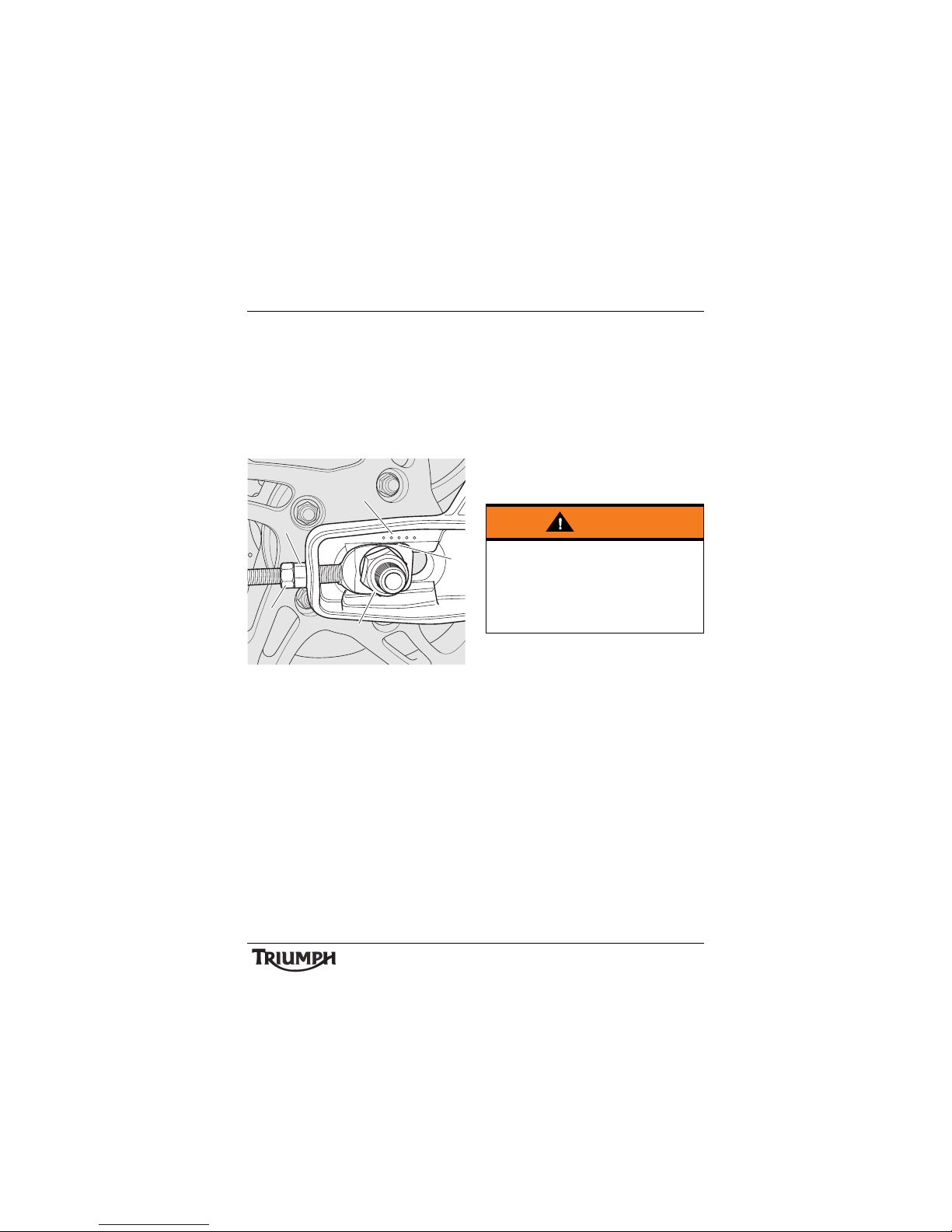
95
Maintenance and Adjustment
Final Drive Belt Tension Adjustment
Note:
• Always adjust drive belt tension at
the tightest point in the drive belt.
• Always adjust drive belt tension with
the motorcycle engine and drive belt
cold.
1. Wheel spindle nut
2. Adjuster nut
3. Adjuster lock nut
4. Adjuster markings
5. Axle adjuster marking
• Loosen the wheel spindle nut.
• Release the lock nuts on both the left
hand and right hand adjusters.
• Moving both adjusters by an equal
amount, turn the adjuster nuts clockwise
to increase drive belt tension and anticlockwise to decrease drive belt tension.
• When the correct amount of drive belt
tension has been set, push the wheel into
firm contact with the adjuster. Ensure the
axle adjuster marking is aligned with the
same adjuster marking on both sides of
the swinging arm.
• Tighten both adjuster lock nuts to
25 Nm and the rear wheel spindle nut
to 110 N m .
• Repeat the drive belt tension check (see
page 90). Re-adjust if necessary.
5
1
3
2
4
s
Warning
Operation of the motorcycle with insecure
adjuster lock nuts or a loose wheel spindle
may result in impaired stability and
handling of the motorcycle. This impaired
stability and handling may lead to loss of
control or an accident.
Page 96
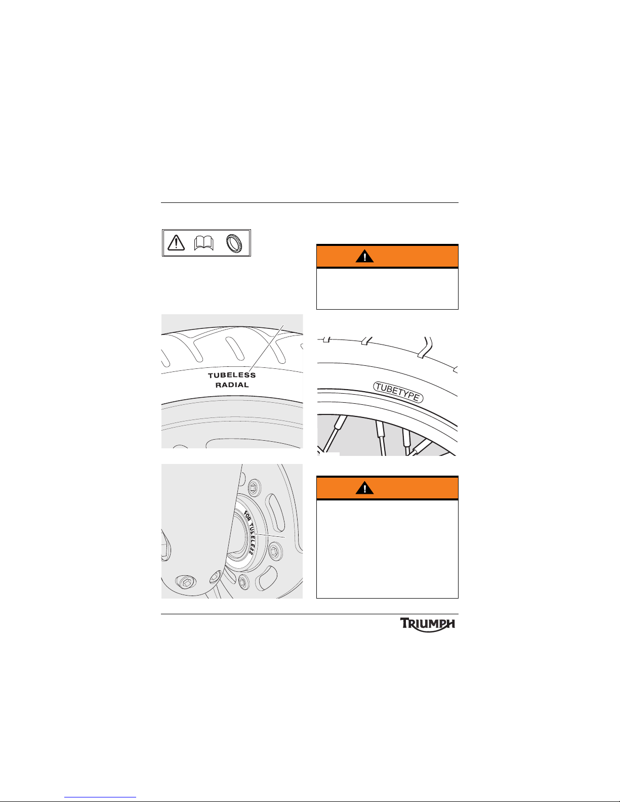
96
Maintenance and Adjustment
Tyres
Thunderbird Commander is equipped with
tubeless tyres, valves and wheel rims. Use
only tyres marked 'TUBELESS' and tubeless
valves on rims marked 'SUITABLE FOR
TUBELESS TYRES'.
1. Ty re ma rk i n g
1. Wheel marking
Thunderbird LT is equipped with spoked
wheels which require a tyre suitable for use
with an inner tube.
1. Tyre marking
cboa
1
cfhb
1
a
Warning
Failure to use an inner tube in a spoked
wheel will cause deflation of the tyre
resulting in loss of motorcycle control and
an accident.
Warning
Do not install tube-type tyres on tubeless
rims. The bead will not seat and the tyres
could slip on the rims, causing rapid tyre
deflation that may result in a loss of vehicle
control and an accident. Never install an
inner tube inside a tubeless tyre. This will
cause friction inside the tyre and the
resulting heat build-up may cause the tube
to burst resulting in rapid tyre deflation,
loss of vehicle control and an accident.
Page 97
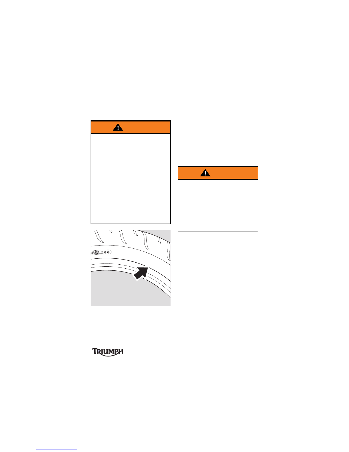
97
Maintenance and Adjustment
Typical Tyre Marking -
Tub e l ess Ty re S u ita b le F or U s e
With An Inner Tube
Tyre Inflation Pressures
Correct inflation pressure will provide
maximum stability, rider comfort and tyre life.
Always check tyre pressures before riding
when the tyres are cold. Check tyre pressures
daily and adjust if necessary. See the
Specification section for details of the correct
inflation pressures.
Tyre Wear
As the tyre tread wears down, the tyre
becomes more susceptible to punctures and
failure. It is estimated that 90% of all tyre
problems occur during the last 10% of tread
life (90% worn). It is therefore not
recommended to use tyres until they are
worn to their minimum.
Warning
Inner tubes must only be used on
motorcycles fitted with spoked wheels and
with tyres marked 'TUBE TYPE'.
Some brands of approved tyres marked
'TUBELESS' may be suitable for use with
an inner tube. Where this is the case, the
tyre wall will be marked with text
permitting the fitment of an inner tube (see
illustration below).
Use of an inner tube with a tyre marked
'TUBELESS', and NOT marked as suitable
for use with an inner tube, or use of an
inner tube on an alloy wheel marked
'SUITABLE FOR TUBELESS TYRES' will
cause deflation of the tyre resulting in loss
of motorcycle control and an accident.
O
N
T
U
B
E
T
Y
P
E
R
I
M
F
I
T
A
T
U
B
E
Warning
Incorrect tyre inflation will cause abnormal
tread wear and instability problems that
may lead to loss of control and an accident.
Under-inflation may result in the tyre
slipping on, or coming off the rim. Overinflation will cause instability and
accelerated tread wear.
Both conditions are dangerous as they may
cause loss of control leading to an accident.
Page 98
98
Maintenance and Adjustment
Minimum Recommended Tread
Depth
In accordance with the periodic maintenance
chart, measure the depth of the tread with a
depth gauge, and replace any tyre that has
worn to, or beyond the minimum allowable
tread depth specified in the table below:
Under 130 km/h
(80 mph)
2 mm (0.08 in)
Over 130 km/h
(80 mph)
Rear 3 mm (0.12 in)
Front 2 mm (0.08 in)
Warning
This motorcycle must not be operated
above the legal road speed limit except in
authorised closed course conditions.
Warning
Only operate this Triumph motorcycle at
high speed in closed course, on-road
competition or on closed course racetracks.
High-speed operation should only then be
attempted by riders who have been
instructed in the techniques necessary for
high-speed riding and are familiar with the
motorcycle’s characteristics in all
conditions. High-speed operation in any
other circumstances is dangerous and will
lead to loss of motorcycle control and an
accident.
Warning
Operation with excessively worn tyres is
hazardous and will adversely affect traction,
stability and handling which may lead to
loss of control and an accident.
When tubeless tyres become punctured,
leakage is often very slow. Always inspect
tyres very closely for punctures. Check the
tyres for cuts, embedded nails or other
sharp objects. Operation with punctured or
damaged tyres will adversely affect
motorcycle stability and handling which
may lead to loss of control or an accident.
Check the rims for dents or deformation.
Operation with damaged or defective
wheels or tyres is dangerous and loss of
motorcycle control or an accident could
result.
Always consult your authorised Triumph
dealer for tyre replacement, or for a safety
inspection of the tyres.
Page 99
99
Maintenance and Adjustment
Tyre R e place m e nt
All Triumph motorcycles are carefully and
extensively tested in a range of riding
conditions to ensure that the most effective
tyre combinations are approved for use on
each model. It is essential that approved tyres
and inner tubes (if installed) fitted in
approved combinations, are used when
purchasing replacement items. The use of
non-approved tyres and inner tubes, or
approved tyres and inner tubes in nonapproved combinations, may lead to
motorcycle instability, loss of control and an
accident.
Different wheel speeds, caused by nonapproved tyres, can affect the function of the
ABS computer.
See the Specification section for details of
approved tyre and inner tube combinations.
Always have tyres and inner tubes fitted and
balanced by your authorised Triumph dealer
who has the necessary training and skills to
ensure safe, effective fitment.
Warning
The ABS computer operates by comparing
the relative speed of the front and rear
wheels. Use of non-recommended tyres
can affect wheel speed and cause the ABS
function not to operate, potentially leading
to loss of control and an accident in
conditions where the ABS would normally
function.
Warning
If a tyre or inner tube sustains a puncture,
the tyre and inner tube must be replaced.
Failure to replace a punctured tyre and
inner tube, or operation with a repaired
tyre or inner tube can lead to instability,
loss of motorcycle control or an accident.
Warning
Inner tubes must only be used on
motorcycles fitted with spoked wheels and
with tyres marked 'TUBE TYPE'.
Use of an inner tube with a tyre marked
'TUBELESS' and/or on an alloy wheel can
lead to loss of motorcycle control and an
accident.
Warning
Do not install tube-type tyres on tubeless
rims. The bead will not seat and the tyres
could slip on the rims, causing rapid tyre
deflation that may result in a loss of vehicle
control and an accident. Never install an
inner tube inside a tubeless tyre. This will
cause friction inside the tyre and the
resulting heat build-up may cause the tube
to burst resulting in rapid tyre deflation,
loss of vehicle control and an accident.
Page 100
100
Maintenance and Adjustment
Warning
If tyre damage is suspected, such as after
striking the kerb, ask your authorised
Triumph dealer to inspect the tyre both
internally and externally. Remember, tyre
damage may not always be visible from
the outside. Operation of the motorcycle
with damaged tyres could lead to loss of
control and an accident.
Warning
Tyres and inner tubes that have been used
on a rolling road dynamometer may
become damaged. In some cases, the
damage may not be visible on the external
surface of the tyre.
Tyres and inner tubes must be replaced after
such use as continued use of a damaged
tyre or inner tube may lead to instability, loss
of motorcycle control and an accident.
Warning
Accurate wheel balance is necessary for
safe, stable handling of the motorcycle. Do
not remove or change any wheel balance
weights. Incorrect wheel balance may
cause instability leading to loss of control
and an accident.
When wheel balancing is required, such as
after tyre or inner tube replacement, see
your authorised Triumph dealer.
Only use self-adhesive weights. Clip on
weights may damage the wheel, tyre or
inner tube resulting in tyre deflation, loss of
motorcycle control and an accident.
Warning
When replacement tyres or inner tubes are
required, consult your authorised Triumph
dealer who will arrange for the tyres and
inner tubes to be selected, in a correct
combination, from the approved list and
fitted according to the tyre and inner tube
manufacturer's instructions.
When tyres and inner tubes are replaced,
allow time for the tyres and inner tubes to
seat to the rim (approximately 24 hours).
During this seating period, ride cautiously
as an incorrectly seated tyre or inner tube
could cause instability, loss of motorcycle
control and an accident.
Initially, the new tyres and inner tubes will
not produce the same handling
characteristics as the worn tyres and inner
tubes and the rider must allow adequate
riding distance (approximately 100 miles
(160 km)) to become accustomed to the
new handling characteristics.
24 hours after fitting, the tyre pressures
must be checked and adjusted, and the
tyres and inner tubes examined for correct
seating. Rectification must be carried out as
necessary.
The same checks and adjustments must
also be carried out when 100 miles
(160 km) have been travelled after fitting.
Use of a motorcycle with incorrectly seated
tyres or inner tubes, incorrectly adjusted
tyre pressures, or when not accustomed to
its handling characteristics may lead to loss
of motorcycle control and an accident.
 Loading...