

Triumph TR6R Tiger 650, TR6C TROPHY 650, T120R Bonneville 120, T12OR BONNEVILLE 120 Replacement Parts Manual
REPLACEMENT
PARTS
CATALOGUE
No.
7
UNIT CONSTRUCTION
40
cu.
ins.
TWINS
TR6R TIGER 650
TR6C TROPHY 650
Tl2OR BONNEVILLE 120
From
engine
No.
DU
85904
TRIUMPH ENGINEERING COMPANY LIMITED
MERIDEN WORKS . ALLESLEY
.
COVENfRY
.
ENGLAND
TELEPHONE MERIDEN
331
TELEGRAMS "TRUSTY COVENTRY"
PUBLISHED SEPTEMBER 1960 REF. SPC.7.

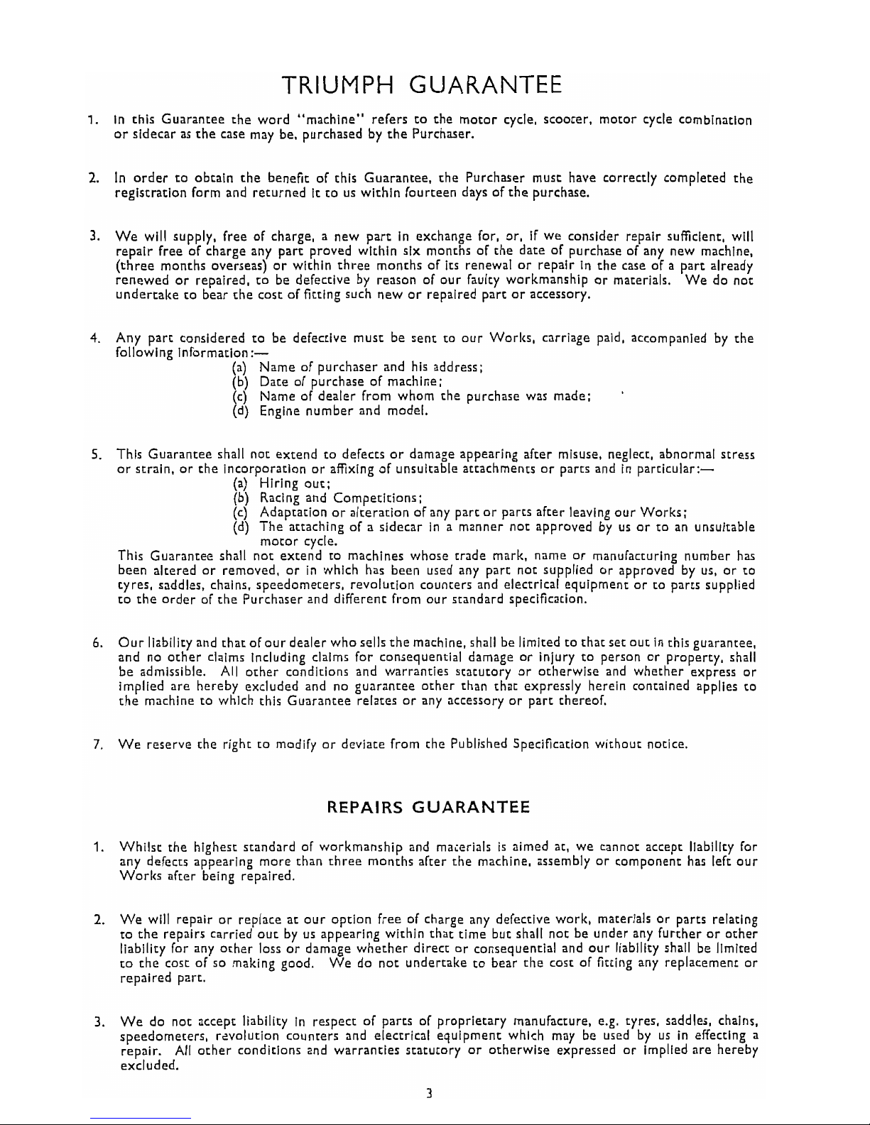
TRIUMPH GUARANTEE
1.
in this Guarantee the word "machine" refers to the motor cycle, scoorer, motor cycle combination
or sidecar as the case may be, purchased by the Purchaser.
2.
In order to obtain the benefit of this Guarantee, the Purchaser must have correctly completed the
3
registration form and returned
it
to us within fourteen days of the purchase.
1
3.
We will supply, free of charge, a new part in exchange for, or, if we consider repair sufficient, will
repair free of charge any part proved within six months of the date of purchase of any new machine,
(three months overseas) or within three months of its renewal or repair in the case of a part already
renewed or repaired, to be defective by reason of our faulty workmanship or materials.
We do not
undertake to bear the cost of fitting such new or repaired part
or
accessory.
4.
Any part considered to be defective must be sent to our Worlcs, carriage paid, accompanied by the
following information:-
(a)
Name of purchaser and his address;
(b) Date of purchase of machine;
(c) Name of dealer from whom the purchase was made;
'
(d) Engine number and model.
5.
This Guarantee shall not extend to defects or damage appearing after misuse, neglect, abnormal stress
or
strain, or the incorporation or affixing of unsuitable attachments or parts and in particular:-
(a) Hiring out;
(b) Racing and Competitions;
(c) Adaptation or alteration of any part
or
parts after leaving our Works;
(d) The attaching of a sidecar in a manner not approved by us or to an unsuitable
motor cycle.
This Guarantee shall not extend to machines whose trade mark, name or manufacturing number has
been altered or removed, or in 'which has been used any part not supplied or approved by us, or to
ryres, saddles, chains, speedometers, revolution counters and electrical equipment or to parts supplied
to the order of the Purchaser and different from our standard specification.
6.
Our liability and that of our dealer who sells the machine, shall be limited to that set out in this guarantee,
and no other claims including claims for consequential damage or injury to person or property, shall
be admissible. Ail other conditions and warranties statutory or otherwise and whether express or
implied are hereby excluded and no guarantee other than that expressly herein contained applies to
the machine to which this Guarantee relates or any accessory or part
thereof.
7.
We reserve the right to modify or deviate from the Published Specification without notice,
REPAIRS GUARANTEE
1.
Whilst the highest standard of workmanship and maierials is aimed at, we cannot accept liability for
any defects appearing more than three months after the machine, assembly or component has left our
Worlcs after being repaired.
2.
We will repair or replace at our option free of charge any defective work, materials or parts relating
to the repairs carried out by us appearing within that time but shall not be under any further
or
other
liability for any other loss or damage whether direct or consequential and our liability shall be limited
to
the cost of so making good. We do not undertake to bear the cost of fitting any replacement or
repaired part.
3.
We do not accept liability in respect of parts of proprietary manufacture, e.g. tyres, saddles, chains.
speedometers, r?volution counters and electrical equipment which may be used by us in effecting a
repair. Ali other conditions and warranties statutory
or
otherwise expressed or implied are hereby
excluded.
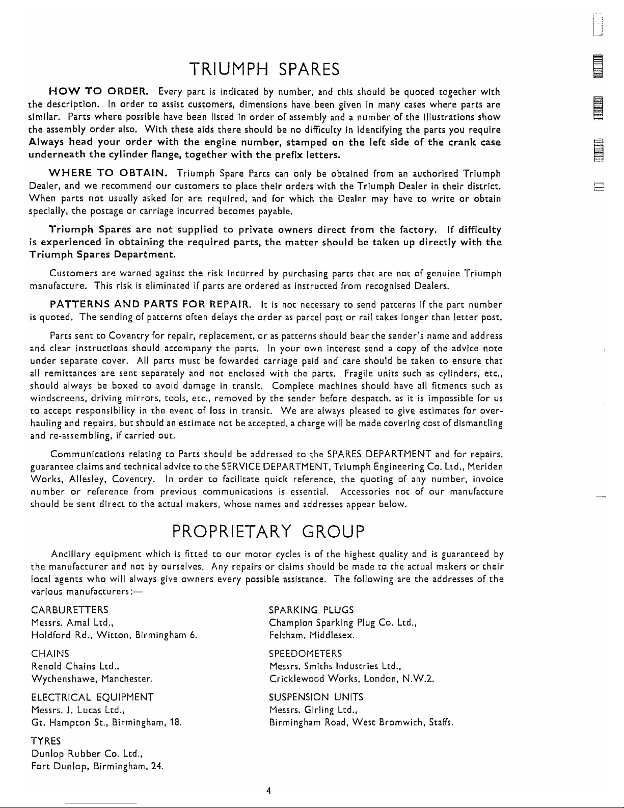
TRIUMPH SPARES
HOW
TO
ORDER.
Every part is indicated by number, and this should be quoted together with
the description. In order to assist customers, dimensions have been given in many cases where parts are
similar. Parts where possible have been listed in order of assembly and a number of the illustrations show
the assembly order also. With these aids there should be no
dificulty in identifying the parts you require
Always head your order with the engine number, stamped on the left side of the crank case
underneath the cylinder flange, together
with
the prefix letters.
WHERE
TO
OBTAIN. Triumph Spare Parts can only be obtained from an authorized Triumph
Dealer, and we recommend our customers to place their orders with the Triumph Dealer in their district.
When parts not usually asked for are required, and for which the Dealer may have to write or obtain
specially, the postage or carriage incurred becomes payable.
Triumph Spares are not supplied to private owners direct from the factory.
If
difficulty
is experienced
in
obtaining the required parts, the matter should be taken up directly
with
the
Triumph Spares Department.
Customers are warned against the risk incurred by purchasing parts that are not of genuine Triumph
manufacture. This risk is eliminated if parts are ordered as instructed from recognised Dealers.
PATTERNS AND PARTS FOR REPAIR.
It
is not necessary to send patterns if the part number
is quoted. The sending of patterns often delays the order
as
parcel post or rail takes longer than letter post.
Parts sent to Coventry for repair, replacement, or
as
patterns should bear the sender's name and address
and clear instructions should accompany the parts.
In your own interest send a copy of the advice note
under separate cover. All
pans must be fowarded carriage paid and care should be taken to ensure that
all
remittances are sent separately and not enclosed with the parts. Fragile units such as cylinders, etc.,
should always be boxed to avoid damage in transit. Complete machines should have all fitments such
as
windscreens, driving mirrors, tools, etc., removed by the sender before despatch, as
it
is impossible for us
to accept responsibility in the event of loss in transit. We are always pleased to give estimates for over-
hauling and repairs, but should an estimate not be accepted, a charge
will be made covering cost of dismantling
and re-assembling, if carried out.
Communications relating to Parts should be addressed to the SPARES DEPARTMENT and for repairs.
guarantee claims and technical advice to the SERVICE DEPARTMENT. Triumph Engineering Co. Ltd.,
Meriden
Works, Allesley, Coventry. In order to facilitate quick reference, the quoting of any number, invoice
number or reference from previous communications is essentizl. Accessories not of our manufacture
should be sent direct to the actual makers, whose names and addresses appear below.
PROPRIETARY GROUP
Ancillary equipment which
is
fitted to our motor cycles
is
of the highest quality and is guaranteed by
the manufacturer and not by ourselves. Any repairs
or
claims should be made to the actual makers or their
local agents who will always give owners every possible assistance. The following are the addresses of the
various manufacturers:-
CARBURETTERS SPARKING PLUGS
Messrs. Amal Lid., Champion Sparking Plug Co. Ltd..
Holdford Rd.. Witton, Birmingham
6.
Feltham. Middlesex.
CHAIFIS
Renold Chains Ltd.,
Wythenshawe. Manchester.
ELECTRICAL EQUIPMENT
Messrs.
J.
Lucas Ltd.,
Gt. Hampton St., Birmingham,
18
SPEEDOMETERS
Messrs. Smiths Industries Ltd.,
Cricklewood Works. London.
N.W.2.
SUSPENSION UNITS
Messrs. Girling Ltd.,
Birmingham Road, West Bromwich. Staffs,
TYRES
Dunlop Rubber Co. Ltd..
Fort Dunlop. Birmingham,
24
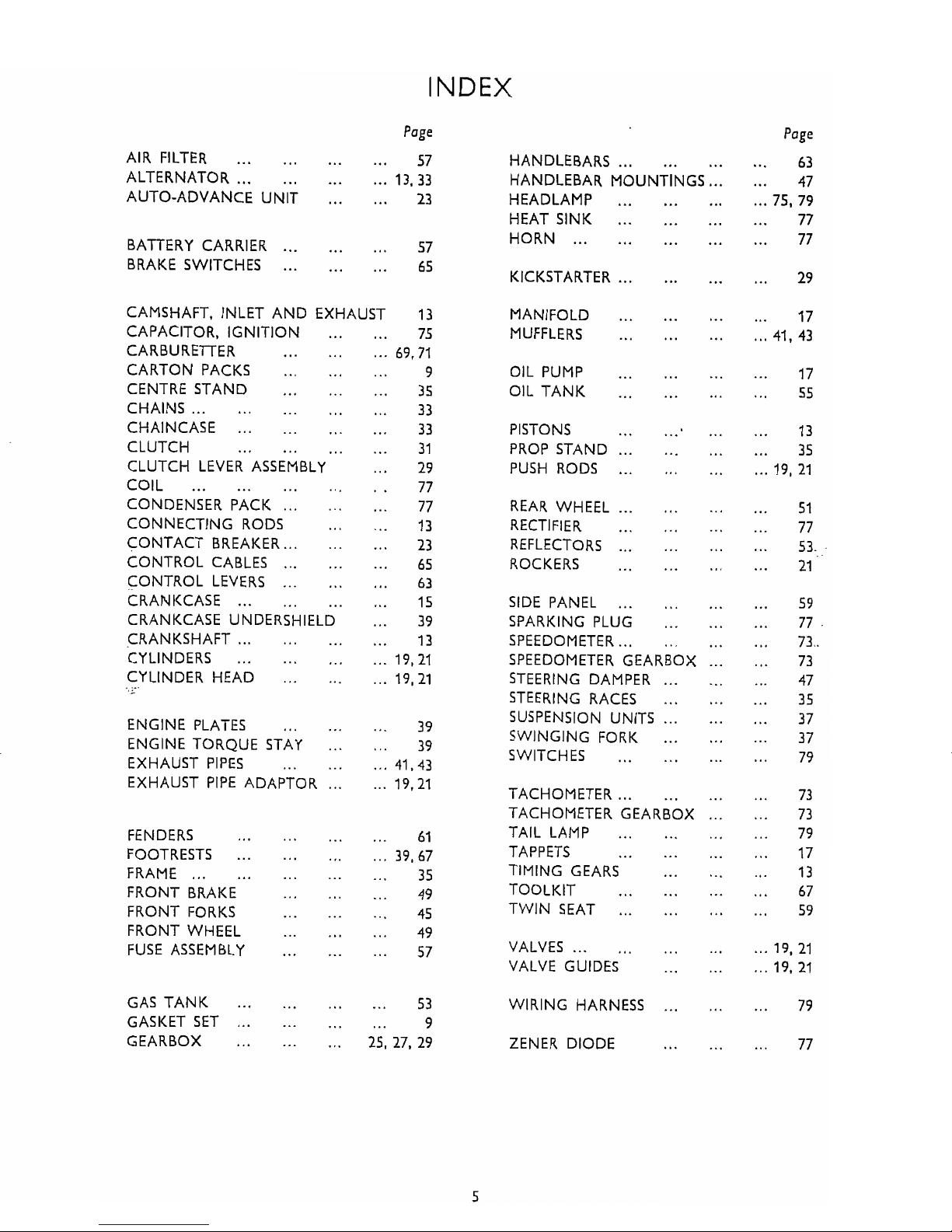
INDEX
Page
Page
AIR FILTER
...
...
...
...
57
ALTERNATOR
...
...
...
...
13 . 33
...
AUTO-ADVANCE UNIT
...
23
......
BATTERY CARRIER
...
57
BRAKE SWITCHES
......
...
65
CAMSHAFT. INLET AND EXHAUST 13
CAPACITOR. IGNITION
...
...
75
CARBURETTER
...
...
...
69 . 71
CARTON PACKS
... ...
...
9
CENTRE STAND
...
...
...
35
CHAINS
......
...
...
...
33
CHAINCASE
......
...
...
33
CLUTCH
...
...
...
...
31
CLUTCH LEVER ASSEMBLY
...
29
COIL
... ...
...
...
.
.
77
CONDENSER PACK
......
...
77
CONNECTING RODS
...
...
13
CONTACT BREAKER
......
...
23
CONTROL CABLES
......
...
65
CONTROL LEVERS
......
...
63
CRANKCASE
......
...
...
15
CRANKCASE UNDERSHIELD
...
39
CRANKSHAFT
......
...
...
13
CYLINDERS
...
...
...
...
19. 21
CYLINDER HEAD
...
...
...
19. 21
....
ENGINE PLATES
...
...
...
39
ENGINE TORQUE STAY
...
...
39
EXHAUST
PIPES
...
...
...
41.43
EXHAUST PIPE ADAPTOR
......
19.21
FENDERS
...
...
...
...
61
FOOTRESTS
...
...
...
...
39. 67
FRAME
...... ...
...
...
35
FRONT BRAKE
...
...
...
49
FRONT FORKS
...
...
...
45
FRONT WHEEL
...
... ...
49
FUSE ASSEMBLY
...
...
...
57
GAS TANK
... ...
...
...
53
......
GASKET SET
...
...
9
...
GEARBOX
...
...
25. 27. 29
HANDLEBARS
......
...
HANDLEBAR MOUNTINGS
...
HEADLAMP
...
...
...
HEAT SINK
...
...
...
HORN
......
... ...
KICKSTARTER
......
...
MANIFOLD
... ...
...
MUFFLERS
...
...
...
OIL PUMP
...
...
...
OIL TANK
...
...
...
PISTONS
...
...
...
PROP STAND
......
...
PUSH RODS
......
...
REAR WHEEL
......
...
RECTIFIER
...
...
...
REFLECTORS
......
...
ROCKERS
... ...
...
SIDE PANEL
......
...
SPARKING PLUG
...
...
SPEEDOMETER
......
...
SPEEDOMETER GEARBOX
...
STEERING DAMPER
......
STEERING RACES
...
...
SUSPENSION UNITS
......
SWINGING FORK
...
...
SWITCHES
...
...
...
TACHOMETER
......
...
TACHOMETER GEARBOX
...
TAIL LAMP
...
...
...
TAPPETS
...
...
...
TIMING GEARS
...
...
TOOLKIT
...
...
...
TWIN SEAT
......
...
VALVES
......
...
...
VALVE GUIDES
...
...
WIRING HARNESS
ZENER DIODE
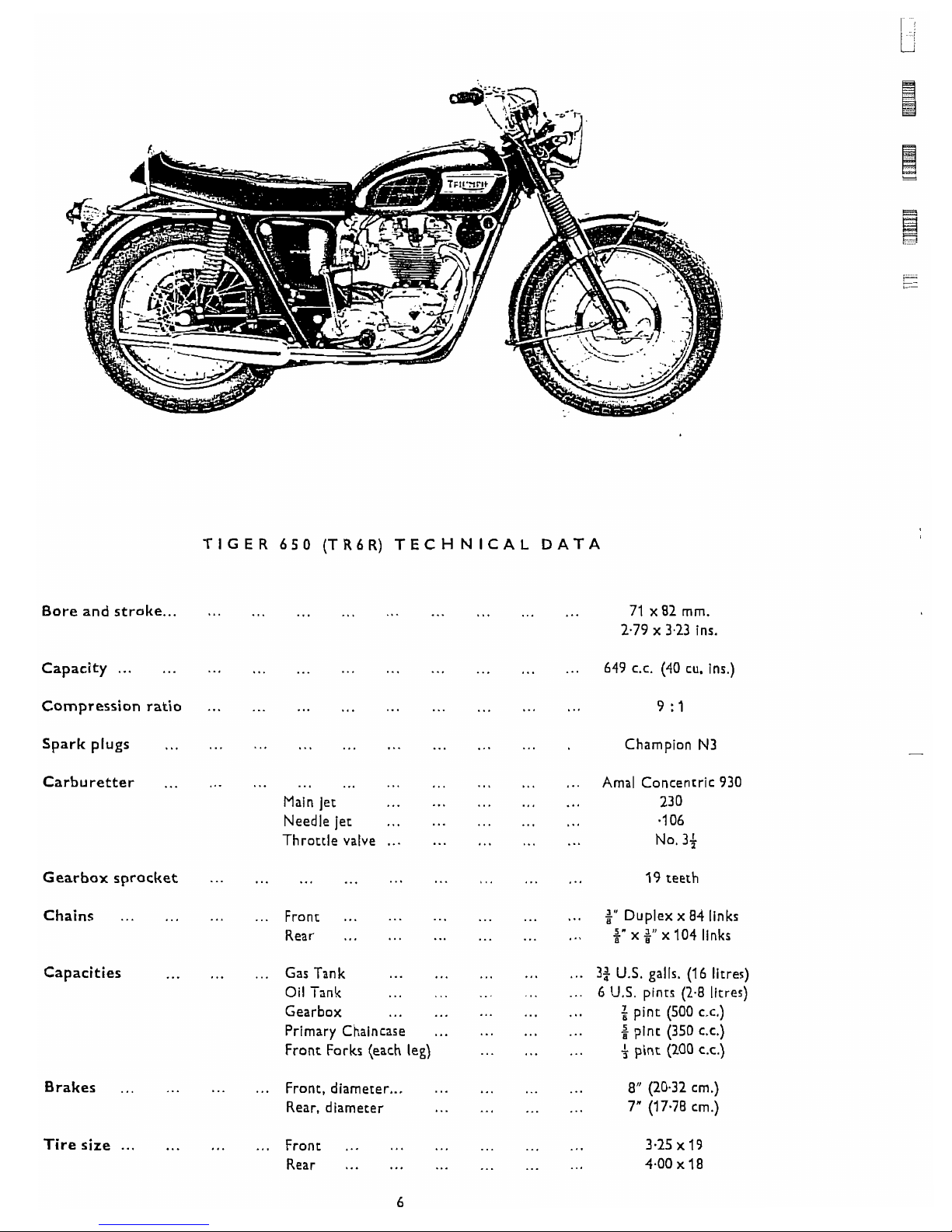
TIGER 650 (TR6R) TECHNICAL DATA
Bore and stroke
......
. , .
...
... ...
...
...
...
...
71 x 82
rnrn.
2.79 x 3.23
ins.
Capacity
...... ...
...
... ...
...
... ...
...
...
649
C.C.
(40
cu. ins.)
Compression ratio
Spark plugs
...
Carburetter
...
Gearbox sprocket
Chains
... ...
Capacities
...
Brakes
...
...
Tire
size
......
.
.
...
...
... ...
Main jet
... ...
Needle jet
...
...
Throttle valve
......
Front
...
...
...
Rear
... ...
...
... ...
Gas Tank
...
...
Oil Tank
...
...
Gearbox
...
...
Primary Chaincase
...
Front Forks (each leg)
...
...
Front, diameter
...
...
Rear, diameter
...
..
Front
...
...
...
Rear
...
...
...
Champion
N3
...
...
...
Amal Concentric
930
...
...
...
230
...
...
...
.I 06
...
...
...
No.
3+
19
teeth
...
...
...
+"
Duplex x
84
links
...
...
...
%"
x x
104
links
...
...
...
3$
U.S.
galls.
(16
litres)
...
...
...
6
U.S.
pints
(2.8
litres)
...
...
...
$
pint
(500
c.c.)
...
...
...
2
pint
(350
c.c.)
...
...
...
f
pint
(200
c.c.)
...
...
...
8" (20.32
cm.)
...
...
...
7" (17.78
cm.)

Bore and stroke
...
TROPHY
650
(TR6C) TECHNICAL DATA
Capacity
......
Compression ratio
Spark plugs
...
Carburetter
...
Gearbox sprocket
Chains
...
...
Capacities
...
Brakes
...
...
Tiresize
......
...
... ...
...
Main jet
...
...
...
Needle jet
...
......
Throttle valve
Front
...
...
...
Rear
...
...
...
Gas Tank
... ...
Oil Tank
...
...
Gearbox
...
. .
,
Primary Chaincase
...
Front Forks (each leg)
...
...
Front, diameter
......
Rear, diameter
.
.
...
Front
... ...
...
Rear
...
...
...
71 x 82 mm.
2.79
x
3.23 ins.
...
...
...
649
C.C.
(40
cu. ins.)
Champion
N3
...
...
...
Amal Concentric 930
...
...
...
230
...
...
...
.I
06
...
...
...
No. 3f
...
...
...
+''
Duplex x 84 links
... ...
...
$"x+"xl04links
...
...
...
2$ U.S. galls. (11 litres)
...
...
...
6
U.S.
pints (1.8 litres)
...
...
...
pint (500
c.c.)
...
...
...
$
pint (350
c.c.)
... ...
...
f
pint (200 c.c.)
...
...
...
8"
(20.32 cm.)
... ...
...
7" (17.78 cm.)
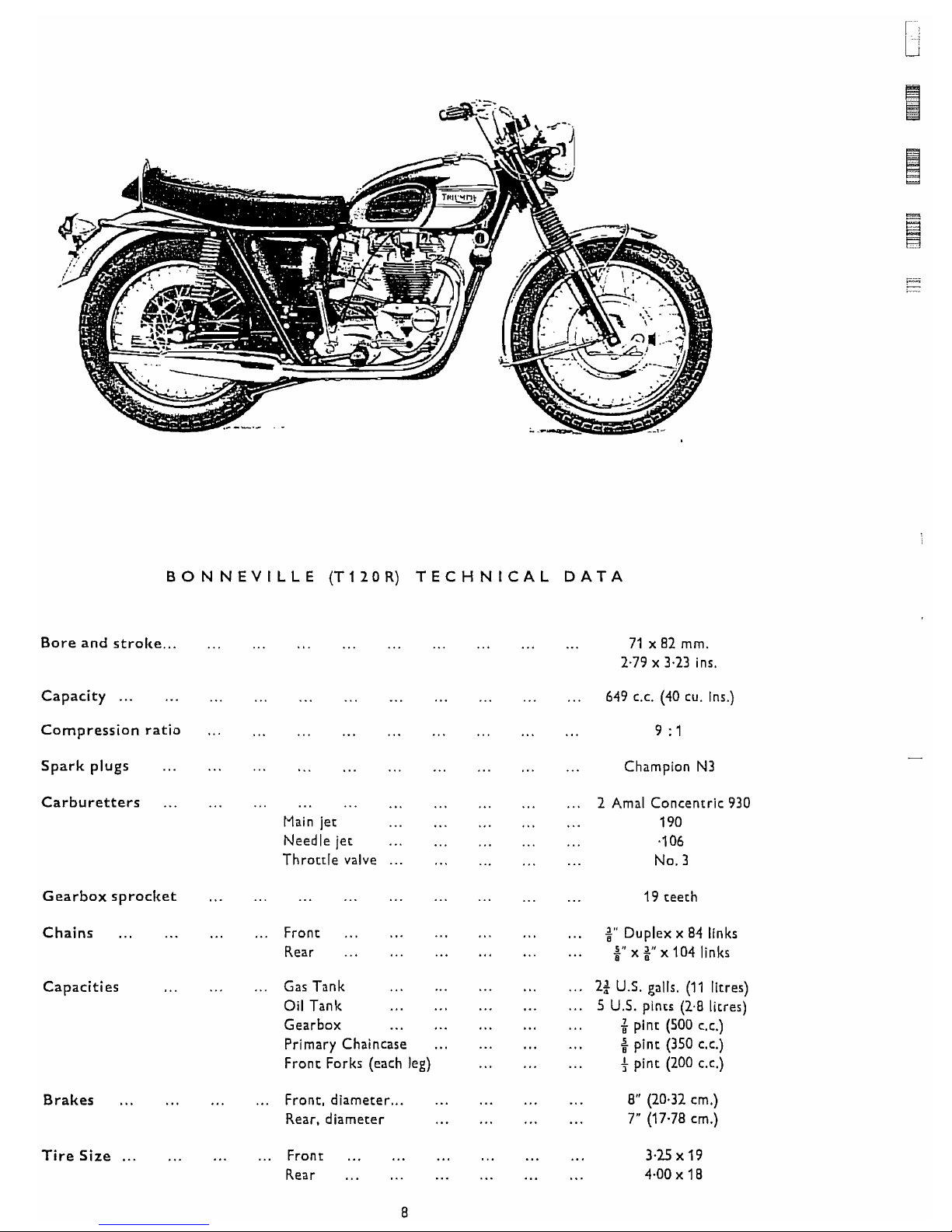
BONNEVILLE (T12OR) TECHNICAL DATA
...
Bore and stroke
Capacity
......
Compression ratio
Spark plugs
...
Carburetters
...
Gearbox sproclcet
Chains
...
...
Capacities
Brakes
... ...
Tire
Size
......
...
...
...
...
Main jet
...
...
Needle jet
...
...
Throttle valve
......
...
...
...
...
...
Front
Rear
...
...
...
...
Gas Tank
...
...
Oil Tank
...
Gearbox
...
...
...
Primary Chaincase
Front Forks (each leg)
...
Front, diameter
......
Rear, diameter
...
Front
...
...
...
...
Rear
...
...
...
71
x 82 mm.
2.79
x
3.23 ins.
...
...
...
649
C.C.
(40 cu. ins.)
... ... ...
9
:I
Champion N3
...
...
...
2 Amal Concentric 930
...
...
...
190
...
...
...
.I
06
...
...
...
No. 3
...
... ...
19 teeth
...
...
...
+"
Duplex x 84 links
... ...
...
x x 104 links
...
...
...
2;
U.5, galls. (11 litres)
...
...
...
5
U.5. pints (2.8 litres)
... ...
...
+
pint (500 LC.)
...
...
...
5
pint (350 c.c.)
...
...
...
f
pint (200 c.c.)
... ...
...
8" (20.32 cm.)
... ...
...
7"
(17.78 cm.)
4
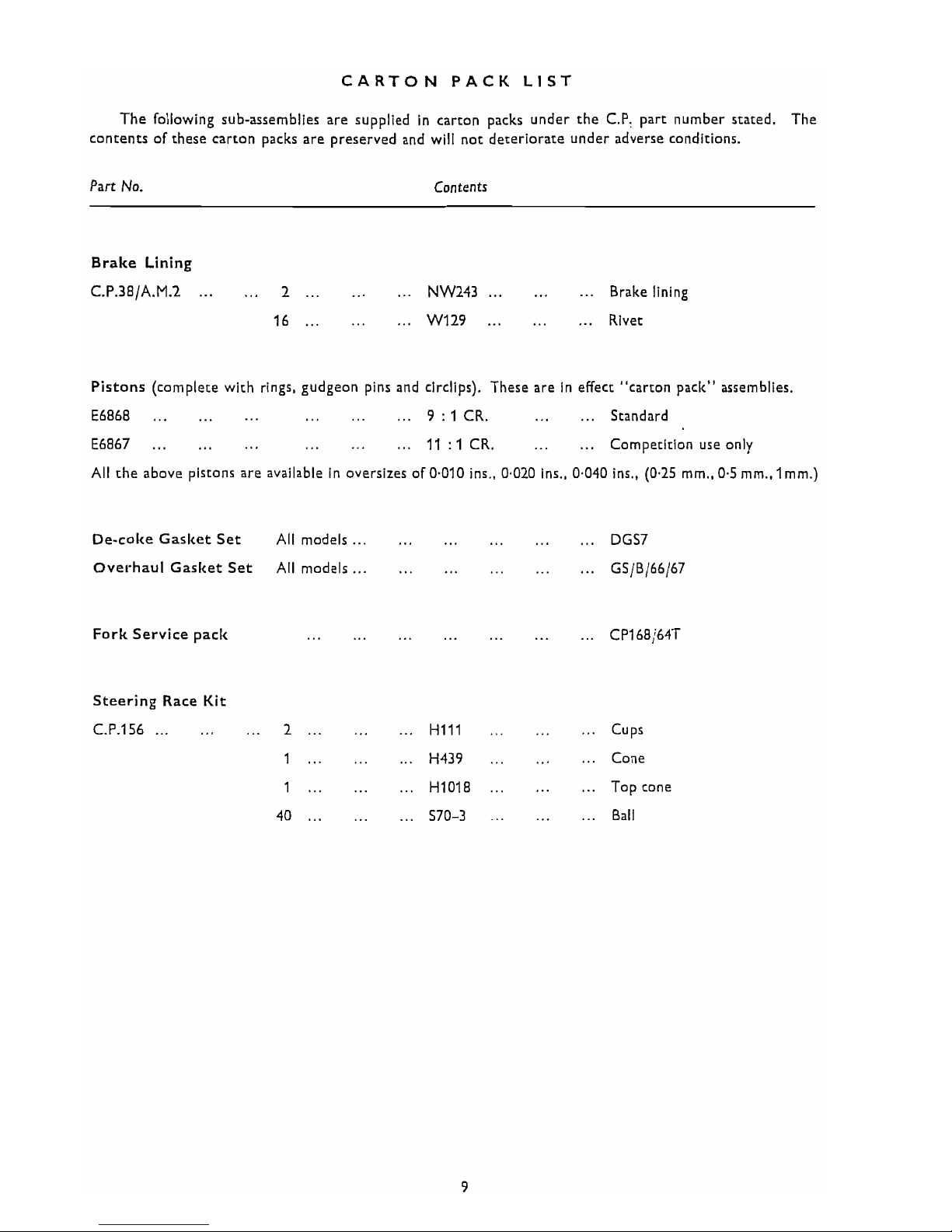
CARTON PACK LIST
1
The following sub-assemblies are supplied in carton packs under the C.P: part number stated. The
contents of these carton packs are preserved and will not deteriorate under adverse conditions.
Part
No.
Contents
Brake Lining
C.P.38/A.M.2
......
2
......
...
NW243
......
...
Brake lining
16
......
...
W129
......
...
Rivet
Pistons (complete with rings, gudgeon pins and circlips). These are in effect "carton pack" assemblies.
E6868
......
...
...
...
...
9
:
1
CR.
...
...
Standard
E6867
......
...
...
...
...
11
:I
CR.
...
...
Competition use only
All the above pistons are available in oversizes of 0.010 ins., 0.020 ins., 0.040 ins., (0.25 mm.,0.5 mm..lmm.)
De-coke Gasket Set All models
......
...
...
... ...
DGS7
Overhaul Gasket Set Ail models
......
...
...
...
...
GS/B/66/67
Fork Service pack
...
...
... ...
...
...
...
CP168,64T
Steering Race Kit
C.P.156
......
...
2...
...
...
HI11
...
... ...
Cups
1
......
...
H439
...
... ...
Cone
1
......
...
HI018
......
...
Top cone
40
......
...
570-3
...
...
...
Ball
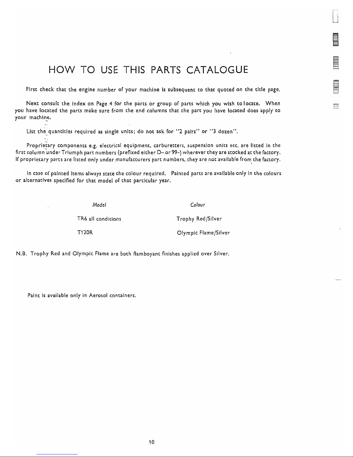
HOW TO USE THIS PARTS CATALOGUE
First check that the engine number of your machine is subsequent to that quoted on the title page.
Next consult the index on Page
4
for the parts or group of parts which you wish to locate.
When
you have located the parts make sure from the end columns that the part you have located does apply to
your machine.
List the quantities required
as
single units; do not ask for "2 pairs" or
"3
dozen".
I.
Proprietary components e.g. electrical equipment, carburetters, suspension units etc. are listed in the
first column~nder~rium~h part numbers (prefixed either D-or99-) whereverthey are stocked atthe factory.
If proprietary parts are listed only under manufacturers part numbers, they are not available from,the factory.
In case of painted items always state the colour required.
Painted parts are available only in the colours
or alternatives specified
for
that model of that particular year.
Model
TR6 all cond~tions
T12OR
Colour
Trophy Red/Silver
Olympic Flame/Silver
N.B.
Trophy Red and Olympic Flame are both flamboyant finishes applied over Silver.
Paint is available only in Aerosol containers.
PLEASE NOTE
i
THROUGHOUT THIS LIST, ASSEMBLIES ARE PRINTED IN CAPITALS AND THE COMPONENTS
INCLUDED IN THAT ASSEMBLY ARE INDENTED IN THE DESCRIPTION COLUMN, REVERTING
TO THE ORIGINAL ALIGNMENT WHEN THE ASSEMBLY IS COMPLETE. TO ORDER THE COMPLETE
ASSEMBLY IT
IS
NECESSARY ONLY TO QUOTE THE ASSEMBLY NUMBER. ANY COMPONENT
PARTS LISTED MAY ALSO BE OBTAINED SEPARATELY IF REQUIRED.
SPECIAL WORKSHOP TOOLS
A COMPLETE LIST OF WORKSHOP TOOLS CAN
BE MADE AVAILABLE BY EITHER CONTACTING
YOUR DEALER OR APPLYING DIRECT TO THE TRIUMPH SERVICE DEPARTMENT.
IN MOST CASES
THESE TOOLS ARE VERY COSTLY AS THEY ARE MADE ENTIRELY FOR WORKSHOP USE. AND
THEREFORE, IT
IS NOT RECOMMENDED THAT THE PRIVATE OWNER PURCHASES THE TOOLS IN
ORDER TO AID SERVICING THE MACHINE ONCE OR TWICE ONLY. IN THESE CIRCUMSTANCES
IT
IS
FAR MORE ECONOMICAL TO GET IN TOUCH WITH A RECOGNISED DEALER.
UNIFIED THREAD FORM
NEW PARTS HAVING THREADED FIXINGS INTRODUCED IN THIS CATALOGUE HAVE THE UNIFIED
FORM OF SCREW THREADS. THIS CHANGEOVER WlLL BE CONTINUED AS AND WHEN NEW PARTS
ARE INTRODUCED. EVEN WHERE PARTS ARE SIMILAR IN APPEARANCE NEW PART NUMBERS
WlLL BE ALLOCATED TO IDENTIFY THE UNIFIED THREADS. ALL NUTS, BOLTS AND STUDS
HAVING THIS THREAD ARE IDENTIFIED BY MARKINGS. BOLTS HAVE A CIRCULAR RECESS IN
THEIR HEADS. STUDS A CIRCULAR GROOVE ON THE END. AND NUTS HAVE INTERLOCKING
CIRCLES ON THE SIDE.
i
I
41 19
io
21 22 23
24
2s
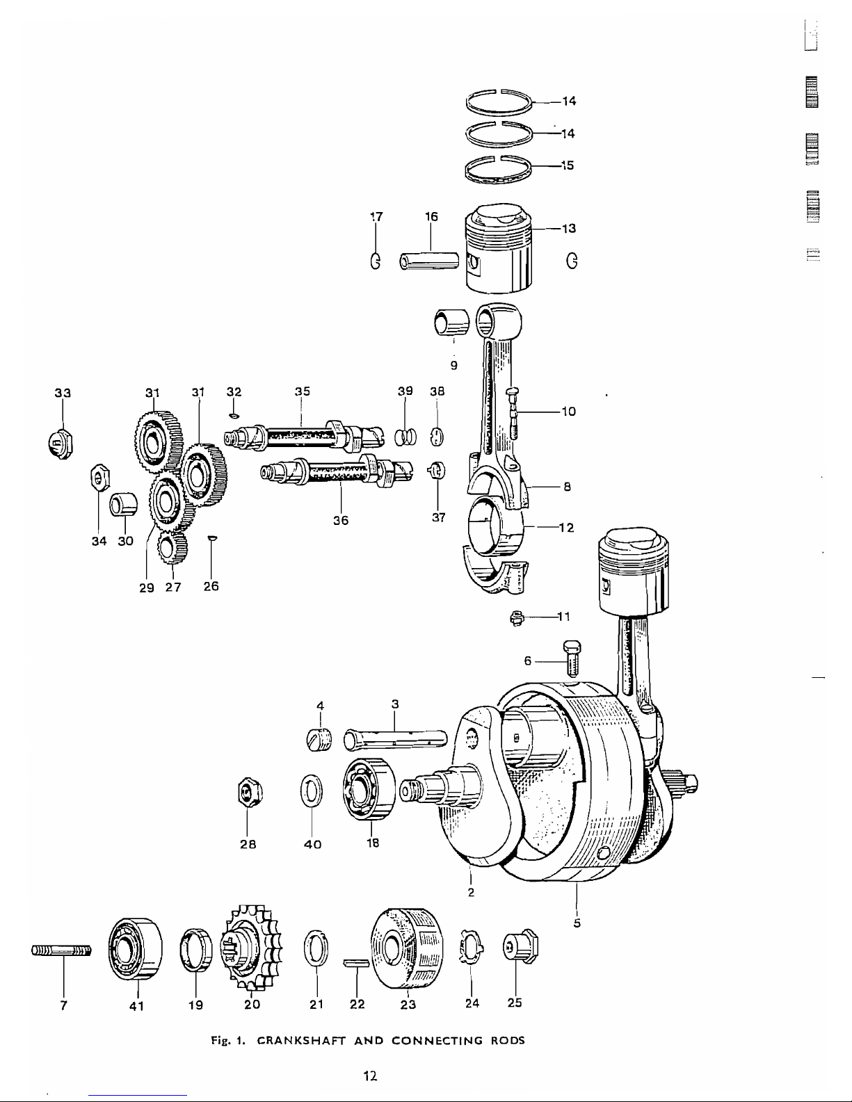
Fig.
1.
CRANKSHAFT AND CONNECTING RODS
Ref
.
No
.
I
-
Part No
.
"E9686
E4643
E3903
E3905
"'E9687
*E9307
E3114
E9S25
El 51 1
E6576
5549
E3586
E6868
E6867
E6864
E6865
E6863
E6869
El 591
E3876
E5446
E4573
E3974
99-0739
E3975
E3977
El580
E4564
E4565
E6159
E400
E4562
El558
El 463
E4563
El
0040
El 0041
i
E4700
E5316
E2256
E3300
E2879
OESCRIP TlON QUANTITY REMARKS
CRANKSHAFT AND CONNECTING RODS
CRANKSHAFT AND FLYWHEEL ASSEMBLY
......
...
1
...
...
CRANKSHAFT
C/W
.
OIL TUBE
...
...
1
... ...
...
...
...
Oil tube
... ...
1
...
...
...
... ...
Screwed plug
...
1
...
...
...
...
...
Flywheel
......
...
1
...
...
... ... ...
Flywheel bolt
... ...
3
... ...
Crankshaft stud (I+ in . O.A.)
......
...
1
...
...
CONNECTING ROD
......
...
...
...
2
...
...
...
...
...
Small end bush
...
...
2
...
...
Connecting rod bolt
...
...
...
...
4
...
...
...
Self locking nut
......
...
...
4
Big end bearing (Available in -.010 in
.
and -.020 in . oversizes) 4
...
...
PISTON COMPLETE 9 : 1 C.R.
...
...
...
2
...
....
PISTON COMPLETE 11 : 1 C.R.
......
...
2
...
...
...
Taper compression ring
......
...
4
...
...
...
...
Oil control ring
......
...
2
...
...
Gudgeon pin (long)
...
...
...
...
2
...
...
...
Circlip
...
...
...
...
...
4
...
...
...
Main bearing. right
...
...
...
...
1
...
...
Oil seal
...
... ...
...
...
... ...
1
...
...
Engine sprocket, 29 teeth Duplex
... ... ...
1
...
...
Distance piece
......
...
...
... ...
1
...
...
...
Rotor key
...
...
...
...
...
1
...
...
...
Rotor (54213901)
...
...
...
...
1
...
...
...
Tab washer
...
...
...
...
...
1
...
...
...
...
...
Nut
...
...
... ...
1
...
...
Key
... ...
...
...
... ... ...
1
......
...
...
Timing pinion
... ...
...
...
1
...
...
Nut
...
...
...
...
... ...
...
1
...
...
...
INTERMEDIATE WHEEL
...
...
...
1
...
...
Intermediate wheel bush
......
...
...
1
...
...
...
Camshaft wheel
......
...
...
...
2
... ...
...
...
...
Camshaft key
... ...
...
2
...
...
...
...
...
...
Inlet camshaft nut
...
1
...
...
...
Exhaust camshaft nut
......
...
...
1
...
...
...
...
Inlet camshaft. Racing type
...
...
1
EXHAUST CAMSHAFT. RACING TYPE
......
...
...
1
...
...
Tachometer drive thimble
...
...
...
1
...
...
...
Rotary breather valve
......
...
...
1
...
Breather valve spring
......
...
...
... ..
1
...
...
...
Clamping washer
...
... ...
...
1
...
...
...
...
...
Main bearing. left
...
...
1
'
Use D524 Loctite Sealant
**
For the commencement of the season. the previous 'light' type of crankshaft
assembly (Part No
.
E7331)
is
fitted . The flywheel only from this assembly bears
Part No
.
E7332
i.
Use E7050 to replace without dismantling motor
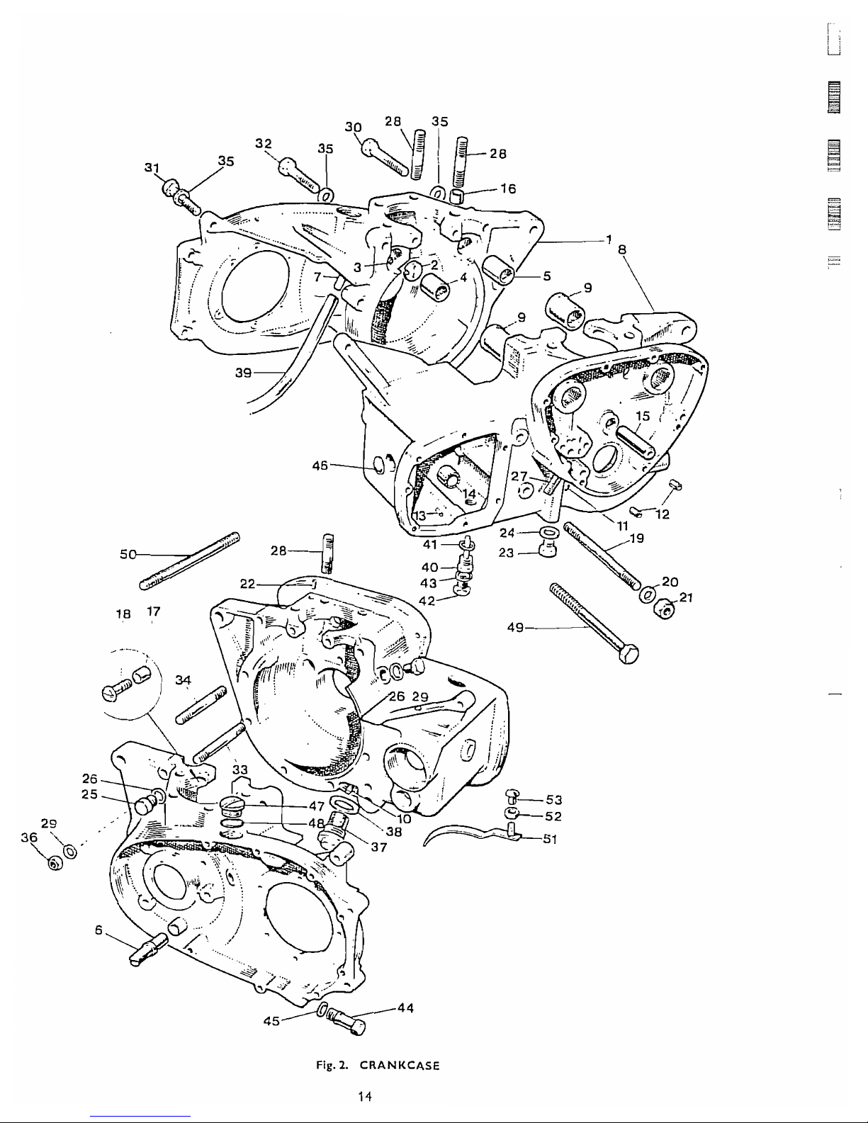
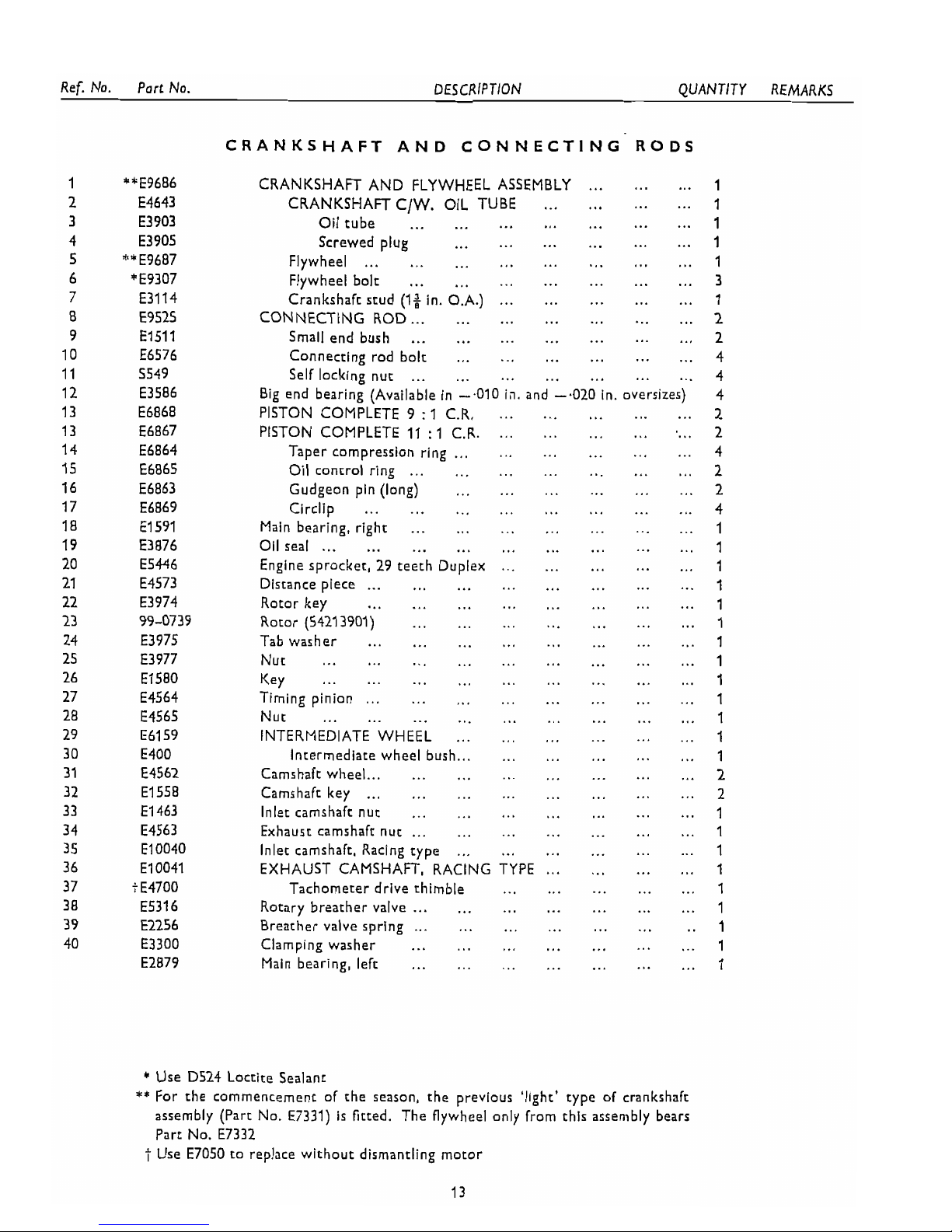
Fig.
2.
CRANKCASE
14
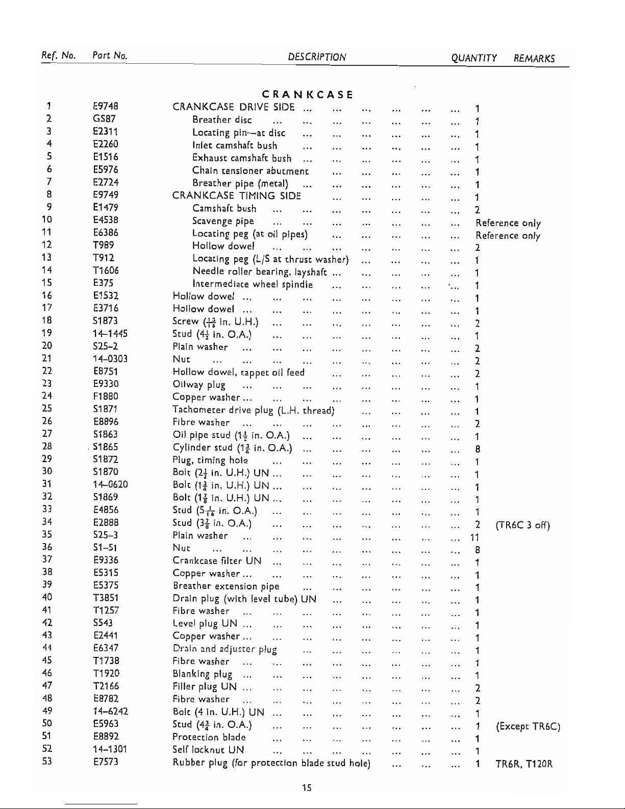
DESCRIPTION
CRANKCASE
...
CRANKCASE DRIVE SIDE
...
Breather disc
...
...
...
Locating pin-at disc
... ...
Inlet camshaft bush
...
...
Exhaust camshaft bush
......
Chain rensioner abutment
...
Breather pipe (metal)
...
...
CRANKCASE TIMING SIDE
...
Camshaft bush
...
...
...
Scavenge pipe
...
...
...
Locating peg (at oil pipes)
...
Hollow dowel
...
...
...
Locating peg (L/S at thrust washer)
Needle roller bearing. layshaft
...
Intermediate wheel spindle
...
Hollow dowel
......
...
...
Hollow dowel
......
...
...
Screw
(s
in . U.H.)
... ...
...
Stud (4f in . O.A.)
...
...
...
Plain washer
...
...
...
...
Nut
...
...
...
...
...
Hollow dowel. tappet oil feed
...
Oilway plug
...
...
...
...
Copper washer
......
...
...
Tachometer drive plug (L.H. thread)
Fibre washer
...
...
...
...
Oil pipe stud (If in . O.A.)
......
Cylinder stud (1: in . O.A.)
......
Plug. timing hole
...
... ...
Bolt (2f in . U.H.) UN
......
...
Bolt (1; in . U.H.) UN
......
...
Bolt (1; in . U.H.) UN
......
...
Stud (5-h in . O.A.)
...
...
...
Stud (3;
in
.
O.A.)
...
...
...
Plain washer
...
...
... ...
Nut
...
...
...
... ...
Crankcase filter UN
......
...
Copper washer
......
...
...
Breather extension pipe
...
...
Drain plug (with level tube) UN
...
F~bre washer
...
...
... ...
Level plug UN
...... ...
...
Copper washer
......
...
...
Drain and adiuzter plug
...
...
Fibre washer
... ...
...
...
Bianting plug
...
...
... ...
Filler plug UN
......
...
...
Fibre washer
... ...
...
...
Bolt (4 in . U.H.) UN
......
...
Stud (4) in . O.A.)
...
...
...
...
Protection blade
...
...
Self locknut UN
... ...
...
Rubber plug (for protection blade stud
I
QUANTITY REMARKS
...
I
...
2
...
Reference only
...
Reference only
...
2
...
1
...
1
....
1
...
1
...
1
...
2
...
1
...
2
...
2
...
2
...
I
...
2
(TR6C 3 off)
...
11
...
8
...
1
...
1
...
I
...
1
...
1
...
2
...
2
...
1
...
1
(Except TR6C)
...
1
... 1
...
1
TR6R. T12OR

ASSY
13
16
24
18
23
20
21
22
Fig.
3.
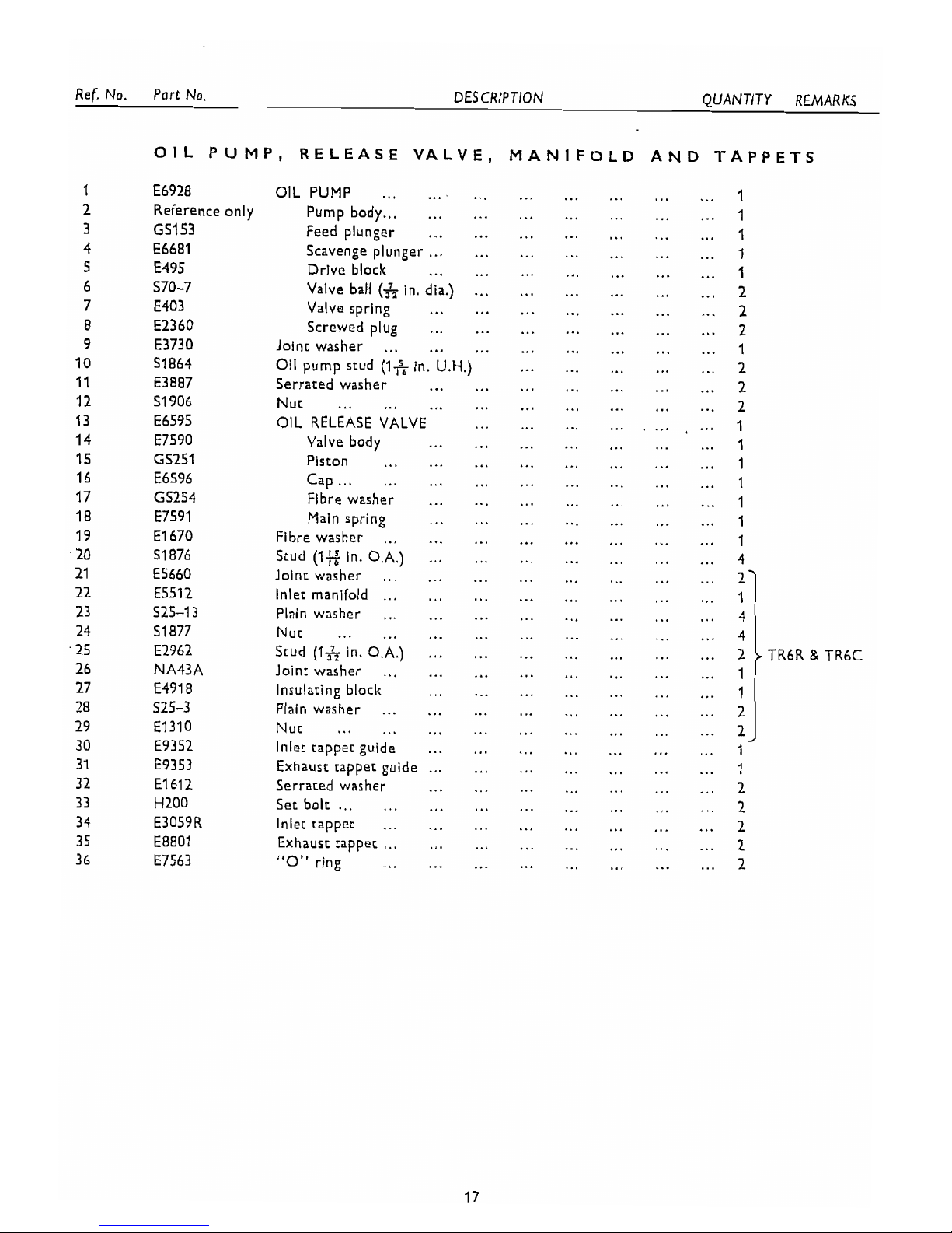
OIL PUMP. RELEASE VALVE, MANIFOLD AND TAPPETS
16
1
I
Ref . No . Port No
.
DESCRIPTION QUANTITY REMARKS
1
OIL PUMP. RELEASE VALVE. MANIFOLD AND TAPPETS
E6928
Reference only
GS153
E6681
E495
570-7
E403
E2360
E3730
51 864
E3887
51 906
E6595
E7590
GS251
E6596
GS254
E7591
El 670
51
876
E5660
E5512
525-1 3
51 877
E2962
NA43A
£491 8
525-3
El310
£9352
E9353
El612
HZ00
E3059R
£8801
E7563
...
... ...
...
OIL PUMP
...
... ...
...
1
...
...
...
...
Pump body
......
...
...
1
...
Feed plunger
...
...
...
...
...
...
1
... ...
...
Scavenge plunger
...
... ... ...
1
...
...
...
...
...
...
Drive block
...
1
...
...
Valve ball
(6
in . dia.)
...
...
...
...
2
...
...
Valve spring
...
...
...
... ...
2
...
... ...
...
...
Screwed plug
...
...
2
...
...
...
...
Joint washer
...
... ...
...
1
... ...
Oil
pump stud
(I*
in
.
U.H.)
...
...
...
2
...
...
...
...
...
...
Serrated washer
...
2
...
...
... ...
...
...
...
Nut
...
...
2
....
OIL RELEASE VALVE
...
...
...
...
...
1
...
...
Valve body
...
...
...
... ...
1
...
...
... ... ...
...
Piston
...
...
1
...
...
Cap
......
...
...
...
...
...
1
...
...
Fibre washer
...
...
... ...
...
1
...
... ...
Main spring
...
...
...
...
1
...
...
... ...
...
...
...
Fibre washer
...
1
...
...
...
Stud
(1E
in . O.A.)
......
... ...
4
...
...
...
...
...
...
...
Joint washer
...
2
......
... ...
...
...
Inlet manifold
...
...
...
...
Plain washer
... ...
...
...
...
...
...
...
Nut
...
...
... ...
...
...
...
Stud (I& in . O.A.)
...
...
...
...
...
...
Joint washer
...
... ... ...
...
...
...
...
...
...
~6 1
&
TR6C
insulating bloclc
...
...
1
...
...
...
Plain washer
... ...
...
...
...
2
...
...
...
... ...
...
Nut
...
... ...
2
... ...
...
...
...
Inlet tappet guide
...
...
1
...
...
Exhaust tappet guide
......
...
...
...
1
...
...
...
...
Serrated washer
...
...
...
2
...
...
...
...
...
Set bolt
......
...
...
2
...
...
...
...
Inlet tappet
...
...
...
...
2
......
...
...
Exhaust tappet
...
...
...
...
2
...
...
...
...
"O-ring
... ...
...
...
2

Fig.
4.
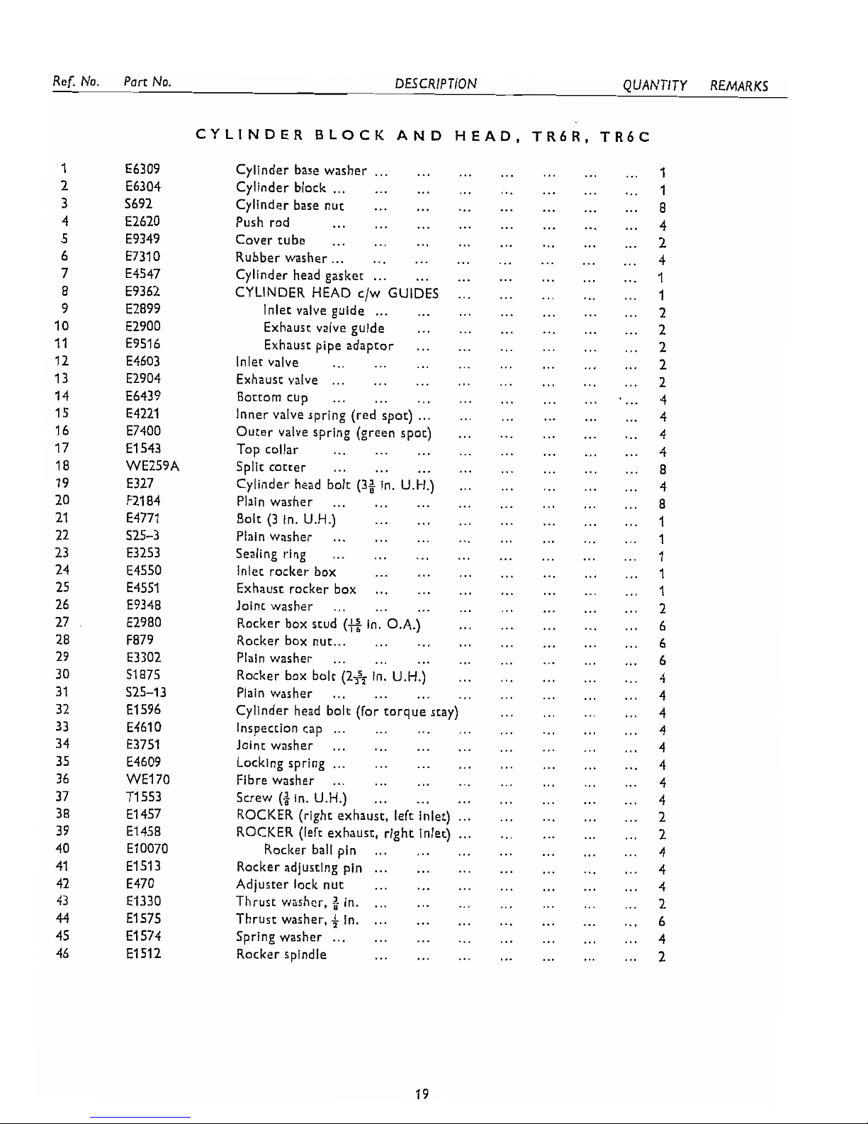
CYLINDER BLOCK AND HEAD, TR6
18
i
Ref. No
.
Part
No
.
DESCRIPTION QUANTITY REMARKS
CYLINDER BLOCK AND HEAD. TR6R. TR6C
Cylinder base washer
......
...
......
Cylinder block
...
...
Cylinder base nut
...
...
...
... ...
Push rod
...
...
Cover tube
... ...
...
...
...
Rubber washer
......
...
Cylinder head gasket
......
...
...
CYLINDER HEAD c/w GUIDES
...
Inlet valve guide
...
...
Exhaust valve guide
...
...
...
Exhausr pipe adaptor
...
...
...
Inlet valve
...
...
Exhausr valve
......
...
. . .
...
...
...
Botrom cup
...
......
Inner valve spring (red spot)
...
Ourer valve spring (green spot)
...
Top collar
...
...
...
...
Split cotrer
...
...
...
.
...
Cylinder head bolt (3i in
U.H.)
...
...
Plain washer
...
...
Bolt (3 in . U.H.)
...
...
...
...
...
...
Plain washer
...
...
Sealing ring
...
...
...
Inlet rocker box
...
...
...
Exhausr rocker box
...
...
...
Joint washer
...
...
...
...
.
...
Rocker box stud
(E
in O.A.)
......
Rocker box nut
...
...
Plain washer
...
...
...
...
.
...
Rocker box bolt (2& in U.H.)
...
Plain washer
...
...
...
Cylinder head bolt (lor torque stay)
...
lnspeccion cap
......
...
...
...
Joint washer
...
...
Locking spring
......
...
...
...
Fibre washer
...
...
...
...
Screw
(i
in . U.H.)
...
...
...
ROCKER (right exhaust. lelt inlet)
...
ROCKER (lelt exhaust. right inlet)
...
Rocker ball pin
...
...
Rocker adjusting pin
......
...
...
Adjuster lock nut
...
...
....
Thrust washer. $ in
...
...
....
Thrust washer. + in
...
...
Spring washer
......
...
...
...
...
Rocker spindle
...
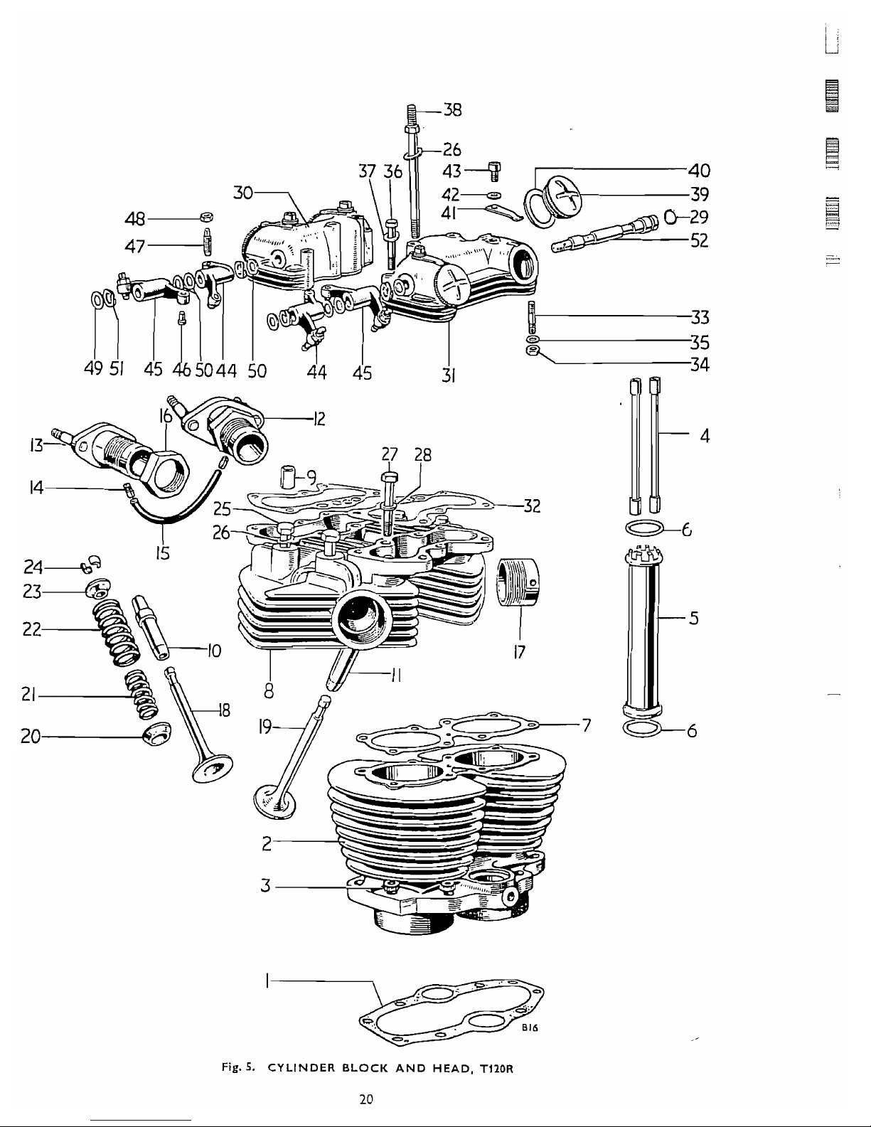
Fig.
5.
CYLINDER BLOCK AND HEAD, TIIOR
20
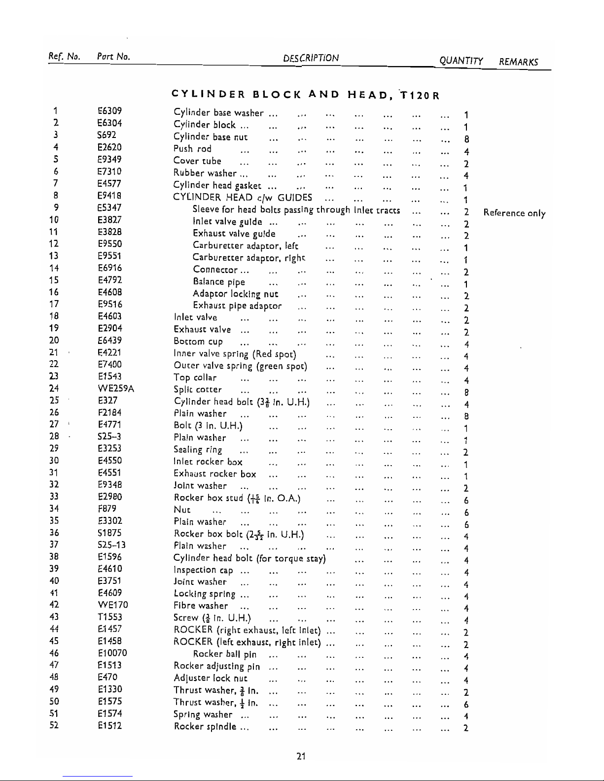
DESCRIPTION QUANTITY REMARKS
CYLINDER
BLOCK
AND HEAD. '~120~
Cylinder base washer
......
...
...
...
... ...
1
Cylinder block
......
......
...
...
... ...
1
Cylinder base nut
...
......
...
...
...
...
8
...
...
...
...
...
Push rod
... ...
...
4
......
...
...
...
Cover tube
... ...
...
2
...
...
...
...
Rubber washer
......
...
...
4
Cylinder head gasket
......
... ... ... ... ...
1
...
CYLINDER HEAD c/w GUIDES
...
...
... ...
1
...
Sleeve for head bolts passing through inlet tracts
2
Reference only
...
Inlet valve guide
......
...
...
...
...
...
2
Exhaust valve guide
...
...
...
...
...
...
2
Carburetter adaptor. left
...
...
...
...
...
1
Carburetter adaptor. right
...
...
...
...
...
1
...
...
...
...
...
Connector
......
...
2
...
...
...
...
Balance pipe
... ...
....
1
Adaptor locking nut
...
...
...
... ...
...
2
...
Exhaust pipe adaptor
...
...
...
...
...
2
...
...
...
...
...
...
...
Inlet valve
...
2
...
...
...
...
Exhaust valve
......
... ...
2
...
...
...
...
Bottom cup
...
... ...
...
4
Inner valve spring (Red spot)
...
...
...
...
...
4
...
Outer valve spring (green spot)
...
...
...
...
4
...
...
...
Top collar
...
...
...
...
...
4
...
...
...
...
Split cotter
...
...
... ...
8
Cylinder head bolt (3t In . U.H.)
... ... ...
... ...
4
...
...
...
...
...
Plain washer
...
...
...
8
...
... ...
...
Bolt (3 in . U.H.)
...
...
...
1
...
... ...
...
...
Plain washer
...
...
...
1
...
...
...
...
...
...
Sealing ring
...
...
2
...
...
...
...
Inlet rocker box
...
...
...
1
...
...
Exhaust rocker box
...
...
...
...
...
1
...
...
...
...
Joint washer
...
...
...
...
2
...
Rocker box stud
(e
In . O.A.)
...
...
...
...
6
... ... ...
...
...
...
Nut
...
...
...
6
...
...
...
...
...
...
Plain washer
...
...
6
...
Rocker box bolt (2& in . U.H.)
...
...
...
...
4
...
...
...
...
Plain washer
... ...
...
...
4
...
...
Cylinder head bolt (for torque stay)
...
...
4
......
...
...
Inspection cap
...
...
...
...
4
...
...
...
...
...
Joint washer
... ...
...
4
Locking spring
......
... ...
...
...
... ...
4
...
...
...
... ...
Fibre washer
...
... ...
4
...
Screw
(+
in . U.H.)
...
...
...
...
...
...
4
......
ROCKER (right exhaust. left inlet)
...
...
...
2
...
ROCKER (left exhaust. right inlet)
......
...
...
2
Rocker ball pin
... ...
...
...
...
... ...
4
Rocker adjusting pin
......
...
...
...
...
...
4
...
Adluster lock nut
...
... ...
...
... ...
4
Thrust washer
.
$
in
....
...
...
... ...
...
...
2
Thrust washer. 4 in
....
...
...
...
...
...
...
6
...
...
Spring washer
......
...
... ... ...
4
...
...
Rocker spindle
...... ...
...
...
...
2
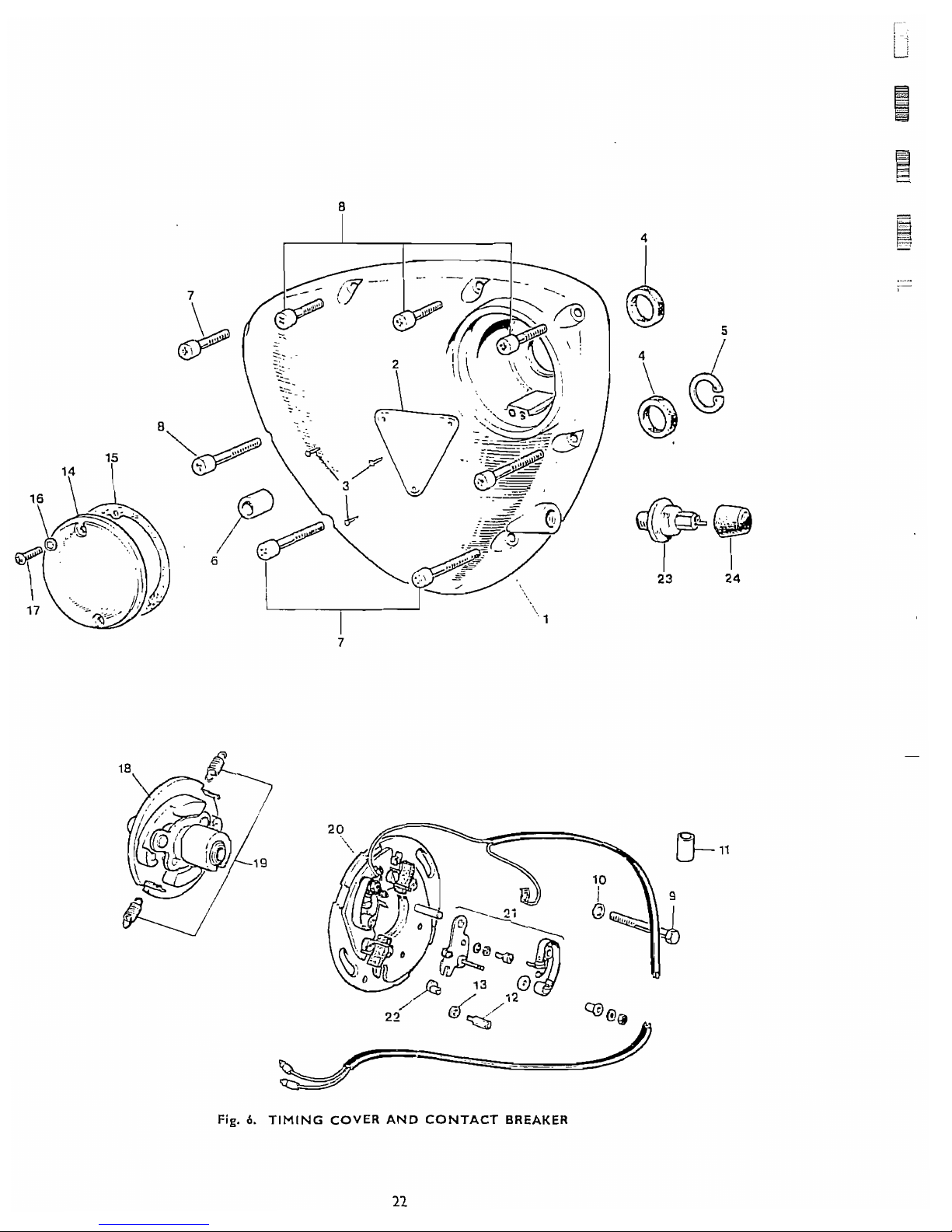
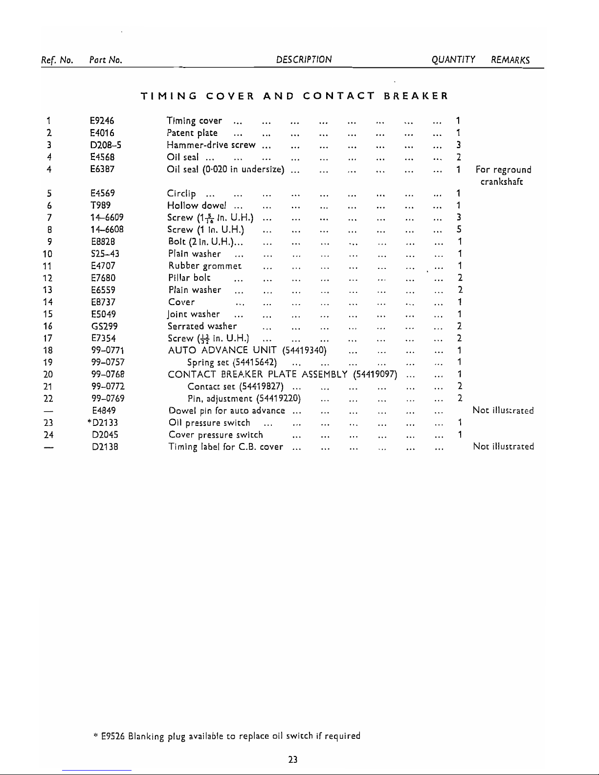
Fig.
6.
TIMING COVER AND CONTACT BREAKER
I
Ref . No . Port No
.
DESCRIPTION QUANTITY REMARKS
TIMING COVER AND
CONTACT
BREAKER
...
...
...
...
Timing cover
... ...
...
...
1
...
... ...
Patent plate
...
... ...
...
...
1
......
...
...
...
Hammer-drive screw
...
...
3
...
...
... ...
...
Oil seal
...
...
...
...
2
Oil seal (0.020 in undersize)
...... ...
...
...
...
1
For reground
crankshaft
...
...
... ...
... ...
Circlip
...
...
...
1
...
...
... ...
Hollow dowel
......
...
...
1
...
...
Screw (Iff In . U.H.)
...
...
...
...
...
3
...
... ... ...
Screw (1 in . U.H.)
...
...
...
5
.
......
...
...
...
Bolt (Zin U.H.)
...
...
...
1
...
...
...
...
...
...
Plain washer
...
...
1
...
...
...
...
...
Rubber grommet
...
...
1
...
...
...
...
...
... ...
Pillar bolt
...
2
... ...
...
...
...
Plain washer
... ...
...
2
...
...
...
...
...
...
Cover
......
1
...
... ...
...
...
...
Joint washer
...
...
1
...
...
...
...
...
Serrated washer
...
...
2
...
... ...
Screw
(5
in
. U.H.)
...
...
...
...
2
...
AUTO ADVANCE UNIT (54419340)
...
...
...
1
...
... ...
...
...
Spring set (54415642)
...
1
......
CONTACT BREP.KER PLATE ASSEMBLY (54419097)
1
......
Contact set (54419827)
...
...
...
...
2
...
...
...
Pin. adjustment (54419220)
...
...
2
Dowel pin lor auto advance
......
...
...
...
...
Not illustrated
... ...
...
...
...
Oil pressure switch
...
...
1
...
...
...
...
...
Cover pressure switch
...
1
Timing label lor C.B. cover
......
...
...
... ...
Not illustrated
*
E9526 Blanking plug available to replace
oil
switch if required
23
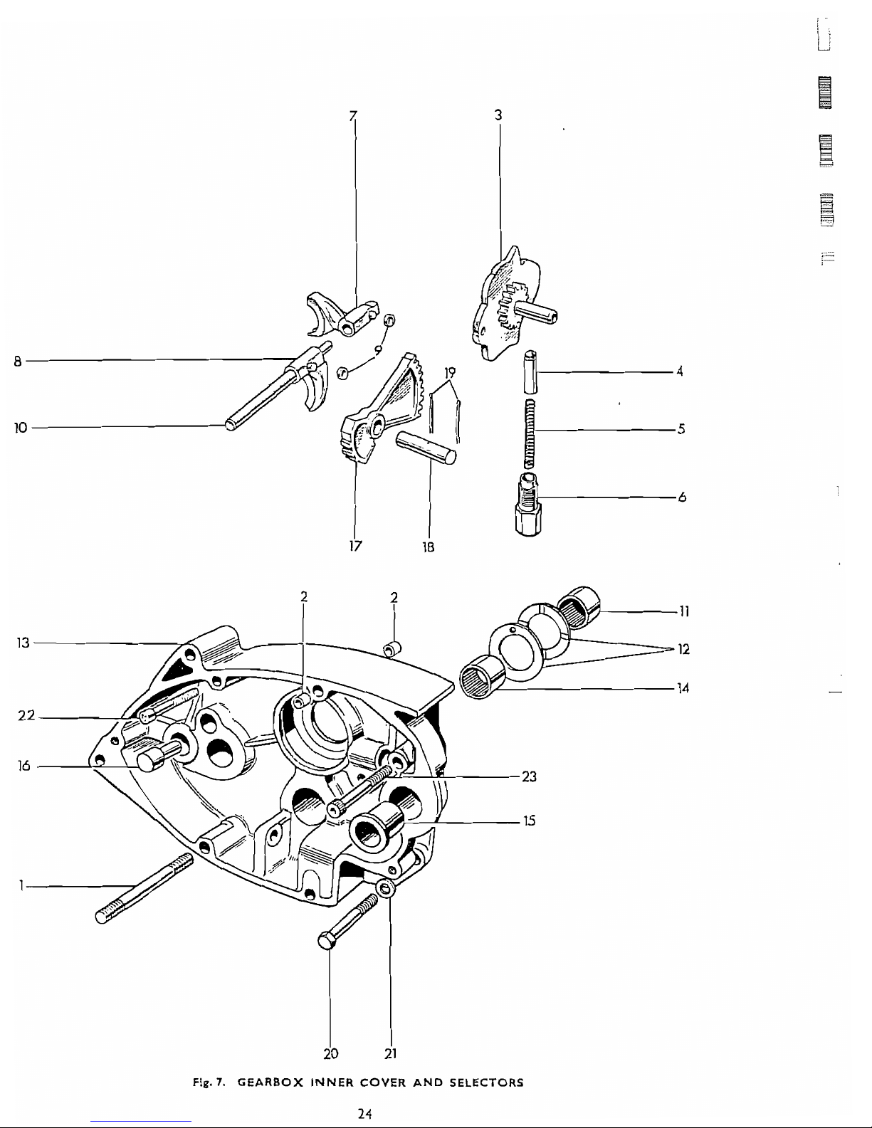
Fig.7.
GEARBOX INNER COVER AND SELECTORS
24
 Loading...