

Page 1
Daytona 675 Motorcycle
Race Kit Manual
© Triumph Designs Ltd 2007. - A9900294 - ADC 4236 issue 1
Page 2

Contents
Introduction. . . . . . . . . . . . . . . . . . . . . . . . . . . . . . . . . . . . . . . . 3
General Information . . . . . . . . . . . . . . . . . . . . . . . . . . . . . . . . . 4
Engine Parts. . . . . . . . . . . . . . . . . . . . . . . . . . . . . . . . . . . . . . . . 6
Head Gasket
0.65mm - A9618072 . . . . . . . . . . . . . . . . . . . . . . . . . . . . . . . . 6
0.60mm - A9618073 . . . . . . . . . . . . . . . . . . . . . . . . . . . . . . . . 6
Cams, Valve Spring & Sprocket Kits . . . . . . . . . . . . . . . . . . . . . . . . . . 7
Cam - Inlet Kit - A9618055 . . . . . . . . . . . . . . . . . . . . . . . . . . . . 7
Cam - Exhaust Kit - A9618056. . . . . . . . . . . . . . . . . . . . . . . . . . 7
Valve Spring Kit - A9618058 . . . . . . . . . . . . . . . . . . . . . . . . . . . 7
Camshaft Sprocket Kit - A9618057. . . . . . . . . . . . . . . . . . . . . . . 7
Cam Chain Kit - A9618059 . . . . . . . . . . . . . . . . . . . . . . . . . . . . . . . . 9
Cam Chain Tensioner Kit (manually adjustable) - A9618060 . . . . . . . . 10
Inlet & Exhaust Valve Kit - A9618061. . . . . . . . . . . . . . . . . . . . . . . . 12
Air Funnel Kit - A9618063 . . . . . . . . . . . . . . . . . . . . . . . . . . . . . . . . 13
Exhaust System, Stage 2 (Arrow) - A9600197. . . . . . . . . . . . . . . . . . 15
Air Filter Kit - A9618075 . . . . . . . . . . . . . . . . . . . . . . . . . . . . . . . . . 19
Slipper Clutch Kit - A9618039 . . . . . . . . . . . . . . . . . . . . . . . . . . . . . 19
Transmission Kits. . . . . . . . . . . . . . . . . . . . . . . . . . . . . . . . . . . . . . 20
1st Gear pair & Housing Kit - A9618066. . . . . . . . . . . . . . . . . 20
Shaft, Input Kit - A9618064 (spares only) . . . . . . . . . . . . . . . 22
Gear, Output Kit - A9618065 (spares only) . . . . . . . . . . . . . . 22
Wheel Detent Kit - A9618068 (spares only) . . . . . . . . . . . . . . 22
Alternator Kit - A9618069 . . . . . . . . . . . . . . . . . . . . . . . . . . . . . . . . 23
Alternator Puller Tool Kit - A3880206 . . . . . . . . . . . . . . . . . . . . . . . . 23
Manual Idle Speed Adjuster Kit - A9618076 . . . . . . . . . . . . . . . . . . . 25
Race ECU Kit - A9618070 . . . . . . . . . . . . . . . . . . . . . . . . . . . . . . . . 26
Race Harness Kit - A9618071 . . . . . . . . . . . . . . . . . . . . . . . . . . . . . 28
Motorcycle Accessories . . . . . . . . . . . . . . . . . . . . . . . . . . . . . . 29
Engine Protector Kits . . . . . . . . . . . . . . . . . . . . . . . . . . . . . . . . . . . 29
Clutch Cover, Carbon Fibre Kit - A9728028 . . . . . . . . . . . . . . . . 29
Crank Cover, Carbon Fibre Kit - A9728029 . . . . . . . . . . . . . . . . 29
Standard Alternator Cover, Carbon Fibre Kit - A9728031 . . . . . . 29
Race Alternator Cover, Carbon Fibre Kit - A9728032 . . . . . . . . . 29
© Triumph Designs Ltd 2007.
Page 2 of 29
Page 3

Introduction
Daytona 675 Race Parts
Triumph's ground-breaking Daytona 675 has not only received global recognition for its
performance on the road, but also for its outstanding ability on the race track. To further
support this exceptional track ability, Triumph have launched a Racing Support Programme,
which is now further complemented by the launch of a range of Triumph Genuine Race Parts.
Factory developed in collaboration with Paul Young Racing, these parts have been designed
to give significant improvements in engine performance for race purposes. This results in
the class-leading Daytona 675 being competitive on the racetrack at the highest level.
Triumph Genuine Race Parts are sold individually and a number of the parts need to be used
in conjunction with each other to ensure the best performance gains are realised and also
to prevent premature wear on associated components. Please ensure you read the user
manual in full to understand this detail prior to fitting or using any of the Triumph Genuine
Race Parts.
© Triumph Designs Ltd 2007.
Page 3 of 29
Page 4
General Information
Please note:
• The race kits detailed in this publication are not covered by any warranty.
• The Race Kit parts covered in this publication are intended for racing purposes only and
any Triumph motorcycle fitted with such kits MUST NOT be used on public roads.
• The information contained in this publication is accurate at the time of final approval,
however, Triumph Motorcycles reserves the right to amend the information at any time
without notice.
• The information provided in this publication should always be used together with the
official Triumph Daytona 675 service manual.
• A standard Triumph Daytona 675 motorcycle fitted with the Race Kits detailed in this
publication will fully comply with the current FIM Supersport regulations.
• Completely read all the instructions before commencing the installation and set up of
the race kit in order to become thoroughly familiar with the kits features and the
installation process.
• When removing components which incorporate a gasket ALWAYS ensure a new gasket
is fitted on re-assembly.
Warnings, Cautions and Notes.
Throughout this publication particularly important information is presented in the following
form:
Warning
This warning symbol identifies special instructions or procedures, which if not correctly
followed could result in personal injury, or loss of life.
Caution
This caution symbol identifies special instructions or procedures, which if not strictly
observed, could result in damage to, or destruction of, equipment.
NOTE
• This note symbol indicates points of particular interest for more efficient and
convenient operation.
© Triumph Designs Ltd 2007.
Page 4 of 29
Page 5
Warning
These accessory kits are for racing only. They are for use solely during closed course
racing. A motorcycle fitted with these kits must not be used on public roads. It is illegal to
use a motorcycle fitted with these kits on public roads. A motorcycle fitted with these kits
does not comply with local laws and regulations. If you use a motorcycle fitted with these
kits on public roads, you may be prosecuted.
Warning
These accessory kits are designed for use on Triumph Daytona 675 motorcycles only and
should not be fitted to any other Triumph model or to any other manufacturer’s
motorcycle. Fitting these accessory kits to any other Triumph model, or to any other
manufacturer’s motorcycle, will affect the performance, stability and handling of the
motorcycle. This may affect the riders ability to control the motorcycle and could cause an
accident.
Warning
Always have Triumph approved parts, accessories and conversions fitted by a trained
technician of an authorised Triumph dealer. The fitment of parts, accessories and
conversions by a technician who is not of an authorised Triumph dealer may affect the
handling, stability or other aspects of the motorcycles operation which may result in loss
of motorcycle control and an accident.
Warning
Throughout this operation, ensure that the motorcycle is stabilised and adequately
supported on a paddock stand to prevent risk of injury from the motorcycle falling.
Warning
A torque wrench of known accurate calibration must be used when fitting this accessory
kit. Failure to tighten any of the fasteners to the correct torque specification may affect
motorcycle performance, handling and stability. This may result in loss of motorcycle
control and an accident.
Warning
If the engine has recently been running, the exhaust system will be hot. Before working
on or near the exhaust system, allow sufficient time for the system to cool, as touching
any part of a hot exhaust could cause burn injuries.
Caution
The use of some of these kits will require changes to the fuelling settings. To alter the
fuelling settings a third party programmable control unit will be required.
© Triumph Designs Ltd 2007.
Page 5 of 29
Page 6
Head Gasket
Caution
The use of the following race kit cylinder head gaskets will require changes to the fuelling
settings. To alter fuelling settings a third party programmable control unit will be
required.
1
*
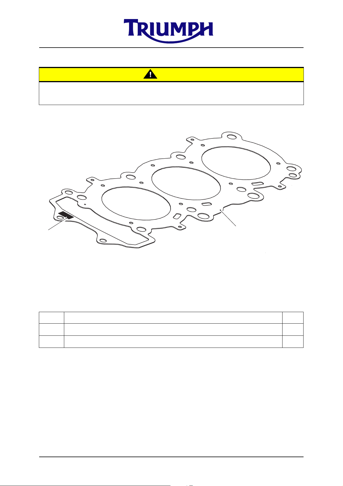
* Thickness “t” marking location
Parts Supplied - A9618072 (0.65mm) or A9618073 (0.60mm)
Item Description Qty
1 Head gasket (t = 0.65mm) 1
1 Head gasket (t = 0.60mm) 1
• The thickness of the standard cylinder head gasket is 0.7mm. The Race Kit
gaskets are available in 0.60mm and 0.65mm thicknesses. The thickness (t)
of the gasket is clearly marked on the gasket in the position (*) shown above.
NOTE
• Use the appropriate gasket to adjust the squish height (squish height is the
gap between the flat portion of the piston and the cylinder head). Always
ensure the gasket chosen provides a minimum squish height of 0.6mm.
1. Remove the existing cylinder head
gasket in line with the procedures
detailed in the Daytona 675 service
manual.
© Triumph Designs Ltd 2007.
Page 6 of 29
2. Fit the chosen race kit cylinder head
gasket following the procedures
detailed in the Daytona 675 service
manual.
Page 7
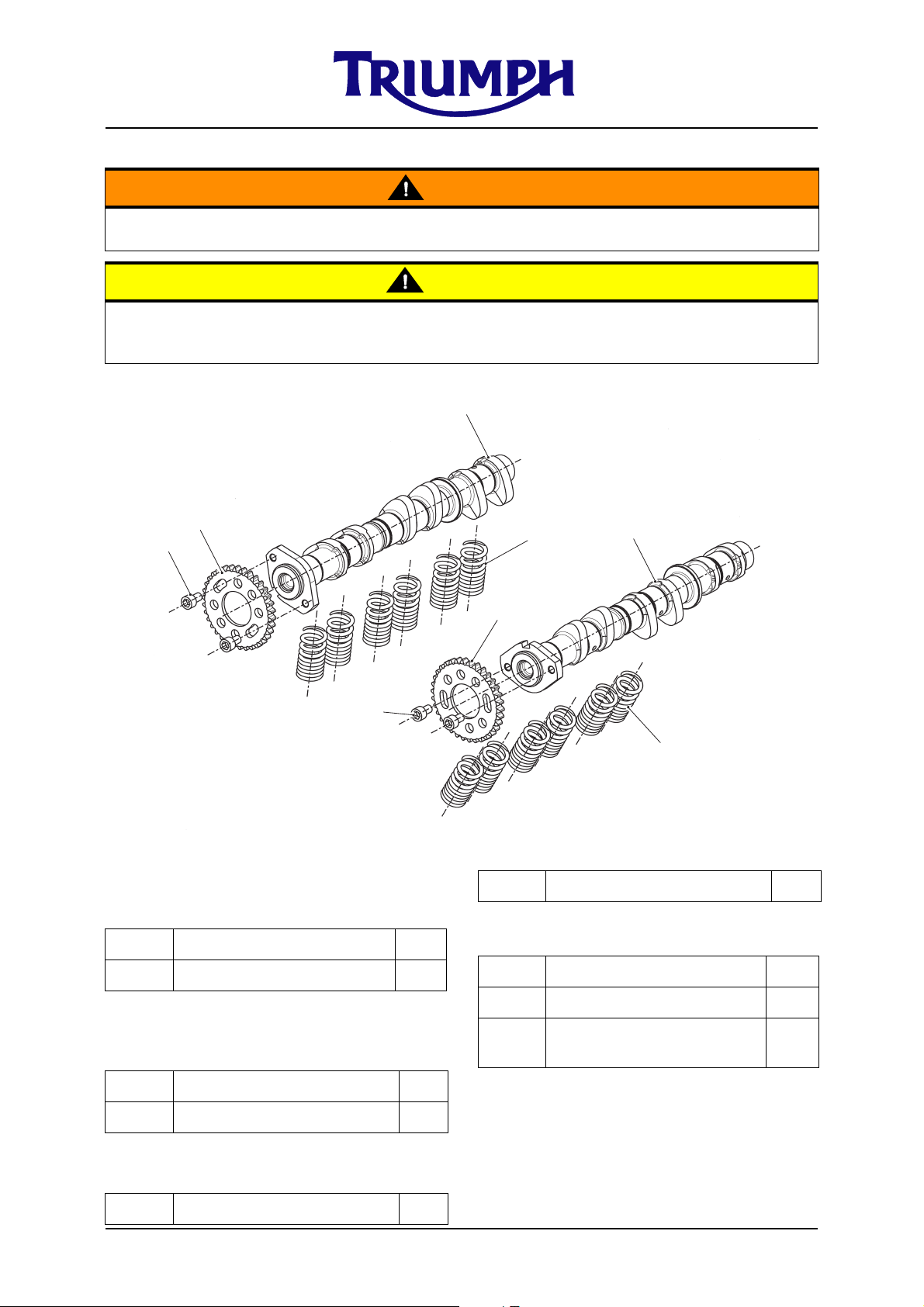
Cams, Valve Spring & Sprocket Kits
Warning
The race kit must be fitted as a complete set. If it is not fitted as a complete set a failure
may result which could cause loss of motorcycle control and an accident.
Caution
The use of the Camshaft, Valve spring & Sprocket race kits detailed below will require
changes to the fuelling settings. To alter fuelling settings a third party programmable
control unit will be required.
1
4
5
5
Parts Supplied
Camshaft Inlet Kit - A9618055
Item Description Qty
3
2
4
3
3 Valve spring, 14.4id, race 12
Camshaft Sprocket Kit - A9618057
1 Cam assy, inlet, race 1
Camshaft Exhaust Kit - A9618056
Item Description Qty
2 Cam assy, exhaust, race 1
Valve Spring Kit - A9618058
Item Description Qty
© Triumph Designs Ltd 2007.
Page 7 of 29
Item Description Qty
4 Sprocket, camshaft, 34T 2
5
Socket head cap screw,
Encapsulated, M6x10
4
Page 8

NOTE
• The standard inlet cam is 9.25mm max lift and 258.50
inlet cam is 9.25mm max lift and 268.74
o
duration.
• The standard exhaust cam is 8.5mm max lift and 246
exhaust cam is 8.5mm max lift and 262.21
o
duration.
o
duration. The race kit
o
duration. The race kit
• The race kit valve spring must be used in conjunction with the standard
spring platforms and retainers. The fitted length of the race springs is the
same as the standard spring.
1. The race kit valve springs should be
assembled in the same manner as the
standard valve springs. Follow the
procedure detailed in section 3 of the
Daytona 675 service manual. Ensure
the springs are installed with the close
wound, colour coded end of the springs
facing downwards, towards the piston.
2. The race kit camshafts should be
assembled in the same manner as the
standard camshafts. Follow the
procedure detailed in section 3 of the
Daytona 675 service manual.
3. The race kit cam sprockets should be
mounted and secured to the camshafts
using the slotted holes in the sprocket.
The slotted holes allow adjustment of
the valve timing. The circular holes in
the sprockets are for Triumph service
tool T3880102 and should not be used
to mount the sprockets to the
camshafts.
5. Always check the inlet and exhaust
piston to valve clearance for the timing
selected to use, before running the
engine. You must ensure both
clearances are adequate. As a guide,
the standard nominal piston to valve
clearance is 1.3mm inlet & 1.5mm
exhaust.
6. When the desired timing has been set
the new socket retaining screws
provided should be tightened to 15Nm.
Note, if the screws are released for any
reason, apply ThreeBond 1305 to the
threads before re-tightening.
NOTE
• No timing marks are included on
the race sprockets. Race engines
will typically have different depths
skimmed off the cylinder head and,
therefore require specific
individual timing.
4. The camshafts should be timed using
cam degreeing equipment which
typically consists of a degree wheel,
pointer, dial indicator and piston stop.
Optimum cam timing will depend on the
exact specification of the engine, but a
recommended starting point is 104
IMOP (Inlet Maximum Opening Point)
and 104
o
EMOP (Exhaust Maximum
Opening Point).
© Triumph Designs Ltd 2007.
Page 8 of 29
o
Page 9
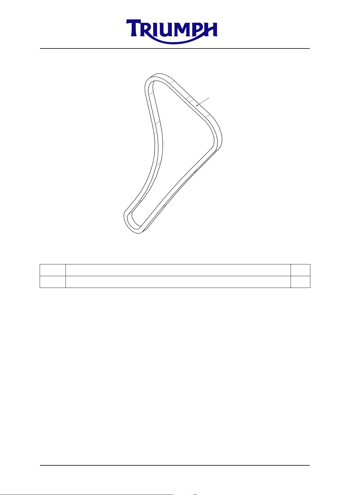
Cam Chain Kit
1
Parts supplied - A9618059
Item Description Qty
1 Cam chain 1
1. Remove the existing cam chain
following the procedures detailed in
section 3 of the Daytona 675 service
manual.
2. Fit the race cam chain following the
procedures detailed in section 3 of the
Daytona 675 service manual.
© Triumph Designs Ltd 2007.
Page 9 of 29
Page 10

Manually adjustable Cam Chain Tensioner Kit
2
1
2
Parts supplied - A9618060
Item Description Qty
1 Tensioner, camchain, manual, assembly 1
2 Bolt, Reduced hex head flange, S/less, M16 X 16, Encapsulated 2
1. Remove the standard tensioner
following the procedure detailed in the
Daytona 675 service manual.
NOTE
• Do not start the motorcycle engine
with the tensioner removed.
2. Thoroughly clean the tensioner
mounting surface on the cylinder head.
3. Remove the crank cover to gain access
to the crankshaft.
4. Back off the plunger locknut on the new
tensioner assembly before installation.
1
© Triumph Designs Ltd 2007.
1. Plunger locknut
Page 10 of 29
Page 11

5. Lightly coat the large O ring with oil,
install the new tensioner assembly and
secure with the new fixings provided.
8. When the slack in the cam chain has
been completely taken up, back off the
plunger by 1/4 turn.
6. Tighten the tensioner fixings to a
torque value of 9Nm.
7. Finger tighten the plunger on the new
tensioner while turning the crankshaft
by hand. At certain points during
engine rotation you will feel the plunger
tighten as it takes up the slack in the
cam chain. DO NOT force the plunger,
continue steady finger tightening only
to take up the slack in the chain as you
rotate the crankshaft.
1
2
9. While holding the plunger in position,
tighten the plunger locknut to a torque
value of 9Nm. Ensure the plunger is
not allowed to turn while tightening the
locknut.
1. Plunger
2. Plunger locknut
© Triumph Designs Ltd 2007.
Page 11 of 29
Page 12

Inlet & Exhaust Valve Kit
Caution
The use of the following race kit Inlet & Exhaust valves will require changes to the fuelling
settings. To alter fuelling settings a third party programmable control unit will be
required.
1
2
Parts supplied - A9618061
Item Description Qty
1 Inlet valve, 29.65 dia 6
2 Exhaust valve, 24.85 dia 6
• The valves supplied in the race kit are used to increase compression ratio, by
having a flat face on the combustion chamber side. They are made from the
same material and have the same mass as the standard valves.
1. Remove the existing inlet and exhaust
valves following the procedure detailed
in section 3 of the Daytona 675 service
manual.
2. The valve seat widths on the race kit
valves are narrower than the standard
valves, therefore the bottom angle
o
(120
) of the cylinder head valve seats
must be modified to ensure the seat on
the head matches the seat on the valve.
© Triumph Designs Ltd 2007.
Page 12 of 29
3. Check the head seat and valve seat are
matched correctly by applying
engineers blue to the cylinder head seat
o
(90
) and then assembling a valve.
4. When the correct match of head seat
and valve seat have been confirmed
assemble the race inlet and exhaust
valves, following the procedure detailed
in section 3 of the Daytona 675 service
manual.
Page 13

Air Funnel Kit
Caution
The use of the following race Air Funnel kit will require changes to the fuelling settings. To
alter fuelling settings a third party programmable control unit will be required.
4
3
2
1
Parts supplied - A9618063
Item Description Qty
1 Air Funnel short, Race 1
2 Air Funnel long, Race 2
3 Fixing retainer 3
NOTE
• It is essential that the race ECU kit - A9618070 is used with the Air Funnel
race kit to allow correct offset for fuelling cylinder 3 (short Air Funnel).
• The parts supplied in the race kit are designed to replace the standard intake
Air Funnels located in the air cleaner box.
• Item 4 (6 off) is the standard fixing supplied with the standard Air Funnel. It
is not supplied in the race kit.
© Triumph Designs Ltd 2007.
Page 13 of 29
Page 14
1. Remove the air cleaner box lid.
2. Remove the standard intake Air
Funnels. Retain the fixings (2 per Air
Funnel) for reuse.
3. Fit the 2 long race kit Air Funnels to
cylinders 1 & 2 and the short Air Funnel
to cylinder 3.
NOTE
• The cylinders are numbered 1 to 3
from left to right of the engine.
4. Fit one of the fixing retainers provided
to each Air Funnel and retain with the
original fixings. Apply ThreeBond 1364
locking compound to the threads only
and tighten the fixings to a torque value
of 6Nm.
5. Fold the retention tabs, on the fixing
retainers, over the 6 fixings as shown
below.
1
2
1. Retention tab
2. Fixing
© Triumph Designs Ltd 2007.
Page 14 of 29
Page 15
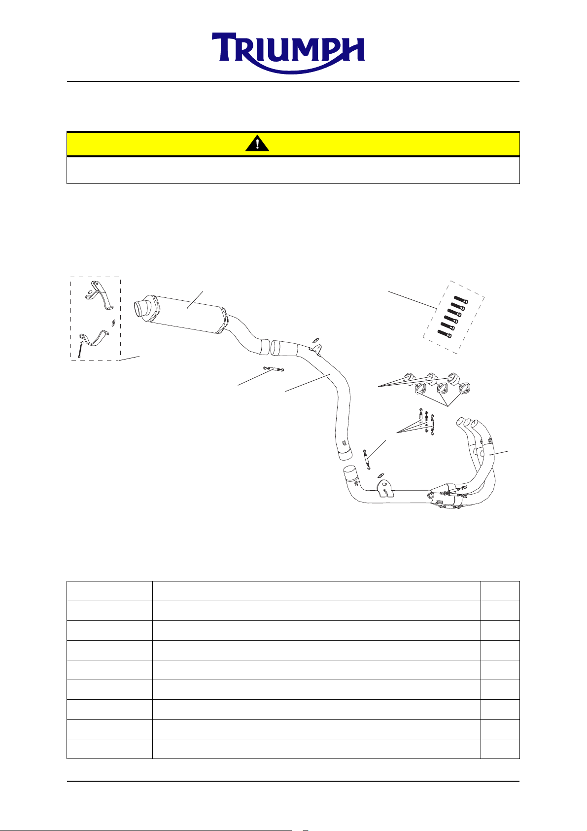
Exhaust system, Stage 2 (Arrow)
Caution
The use of the Arrow Stage 2 exhaust system will require changes to the fuelling settings.
To alter fuelling settings a third party programmable control unit will be required.
Parts supplied - A9600197
Item Description Qty
1 Downpipe collector assy 1
2 Intermediate pipe 1
3 Silencer 1
4Spring 5
5 Primary header bushing 3
6 Primary header flange 3
7 Silencer bracket assembly 1
8 Capscrew, M8 6
© Triumph Designs Ltd 2007.
Page 15 of 29
Page 16

1. Remove the seat, battery, rear
bodywork, lower fairings, radiator,
radiator fan, rear light, pillion foot rest
hangers and exhaust system following
the procedures detailed in the Daytona
675 service manual.
2. Remove the exhaust valve actuator
from its actuator cables.
4. Apply silicone sealant to the mating
surface of the primary header bush
which contacts the cylinder head, the
recommended sealant is Dow Corning
Firestop 700 white silicone.
5. Fit the three primary header bushes to
the cylinder head and secure in the
orientation shown below using the
primary header flanges and M8 cap
screws provided.
3. Remove and discard the exhaust
gaskets and M8 studs from the cylinder
head.
1
2
1. M8 Stud
2. Gasket
NOTE
• To obtain maximum performance
the exhaust port should be
machined, removing material from
the area shown in red. The exhaust
port shape should match the inside
surface of the primary header
bush.
NOTE
• The flat on the primary header
bush should be aligned with the
flat in the exhaust port such that
none of the exhaust port is
obscured by the primary header
bush.
1
1. Flat - primary header bush
© Triumph Designs Ltd 2007.
Page 16 of 29
Page 17

6. Position the downpipe collector
assembly to the underside of the engine
and insert the downpipe ends fully into
the primary header bushes. Secure
with the three springs provided. Ensure
the spring mounting holes are
positioned as shown below for all three
flanges.
8. Insert the end of the intermediate pipe
into the collector pipe in the orientation
shown below. Secure with the spring
provided.
3
1
2
cdyu
1. Down pipe
2. Spring
3. Spring mounting hole position
7. Loosely secure the assembly to the
original exhaust mounting point using
the original fixings.
1
2
1. Intermediate pipe
2. Spring
9. Loosely secure the intermediate pipe to
the exhaust mounting point using the
original fixing as shown.
2
1. Exhaust mounting point
2. Original fixings
© Triumph Designs Ltd 2007.
1. Intermediate pipe
2. Original fixing
1
Page 17 of 29
Page 18
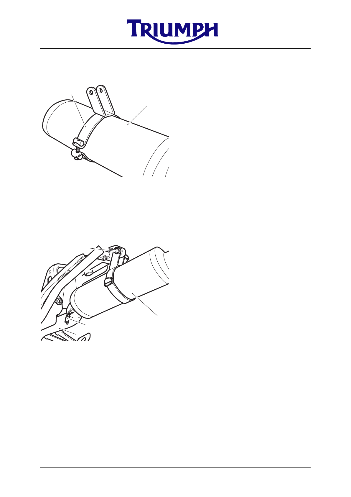
10. Assemble the silencer clamp/bracket
and loosely fit to the silencer in the
orientation shown below.
2
1
1. Silencer
2. Silencer clamp/bracket
11. Fit the silencer to the intermediate pipe
and secure with the spring provided.
Loosely secure the silencer bracket/
clamp to the silencer mounting point
using the original fixings.
4
12. Check the exhaust system is correctly
aligned with the rear frame and tighten
the fixings to the following torque
values; Rear exhaust mounting point
27Nm. Silencer bracket fixing 9Nm.
Intermediate pipe mounting point fixing
22Nm. Collector pipe front mounting
point fixings 15Nm. Primary header
flanges, M8 cap screws 19Nm.
13. If fitting the oxygen sensor use the
adaptor provided and tighten the
sensor to a torque value of 25Nm.
14. Fit the correct specification spark plugs
as recommended below.
NOTE
• Triumph recommends two options
of spark plug. Choose the correct
option depending on the engine
compression ratio. For a standard
compression ratio use NGK
CR10EIX. For high compression
ratio engines use NGK R0373A.
Always ensure there is sufficient
clearance between spark plug and
piston, before attempting to start
the engine.
3
2
1. Silencer
2. Intermediate pipe
3. Spring
4. Silencer mounting point
15. Refit the radiator, rear bodywork, lower
fairings, battery and seat as described
in the Daytona 675 service manual.
NOTE
• The radiator fan, rear light and
pillion foot rest hangers are NOT
refitted.
1
© Triumph Designs Ltd 2007.
Page 18 of 29
Page 19

Air Filter Kit
2
2
Parts supplied - A9618075
1
Item Description Qty
1Air filter 1
2 Retaining washer 3
NOTE
• This kit is supplied by BMC Air Filters. For fitment details refer to the
instruction contained in the kit.
• If you have any queries with regard to the Air Filter kit, in the first instance
contact BMC. For contact details see; www.bmcairfilters.com.
• Loctite or similar should NOT be applied to the fixings as described in the
supplied instructions as this could strip the insert out of the plastic moulding
when removing the filter. The kit is supplied with 3 plastic washers to retain
the fixings. The 3 plastic retaining washers should be fitted to the 3 rear
fixings as shown above. Tighten the fixings to a torque value of 4Nm.
Slipper clutch Kit - A9618039
• The slipper clutch kit is supplied by STM trading s.r.l. For fitment details refer
to the instruction contained in the kit.
• If you have any queries with regard to the slipper clutch kit, in the first
instance contact STM. For contact details see; www.slipperclutch.com.
© Triumph Designs Ltd 2007.
Page 19 of 29
Page 20

Transmission Kit
Warning
The race kit must be fitted as a complete set. If it is not fitted as a complete set a failure
may result which could cause loss of motorcycle control and an accident.
9
7
1
8
4
5
3
Parts supplied
1st gear pair & housing kit - A9618066
6
2
Item Description Qty
1 Input shaft assembly 1
2 Output gear 1
3 Spacer, clutch 1
4 Bearing retainer plate 1
5 Bolt, Reduced hex head flange, M6 x 20, black, encapsulated 3
6 Circlip, 28mm 2
7 Wheel detent 1
8 Screw, torx head, M6 x 20, black 1
9 Washer, splined, 28 x 34 1.5 1
NOTE
• The standard first gear ratio is 34/13 (2.615).
• The race kit first gear ratio is 37/16 (2.313).
© Triumph Designs Ltd 2007.
Page 20 of 29
Page 21

A9618066 - 1st gear pair & housing
1. Remove the existing output shaft
assembly from the engine following the
procedures detailed in section 7 of the
Daytona 675 service manual.
2. Remove the output shaft bearing and
plain thrust washer from the existing
output shaft assembly.
3. Replace the existing 1st gear with the
race kit 1st gear (2) supplied. Ensure
the orientation of the race kit 1st gear
is the same as the standard 1st gear.
Lubricate the 1st gear and 1st gear
bush with clean engine oil during
assembly.
4. Re-assemble the plain thrust washer
and output shaft bearing onto the
output shaft.
5. Remove the existing selector drum
assembly from the engine following the
procedures detailed in section 7 of the
Daytona 675 service manual.
6. Remove the existing detent wheel and
fixing from the selector drum assembly.
Note how the detent wheel is timed
relative to the selector drum by way of
a dowel.
7. Assemble the race kit detent wheel (7)
to the selector drum assembly,
ensuring it is timed to the drum in the
same way as the original detent wheel.
8. Fit the M6 Torx head screw (8) to the
selector drum assembly and tighten to
a torque value of 12Nm. Ensure the
detent wheel (7) is fully inserted into
the bearing, up to its shoulder.
9. Remove the existing input shaft from
the engine following the procedures
detailed in section 7 of the Daytona 675
service manual.
10. Remove all gears, circlips, bushes and
washers from the original input shaft,
taking care to note the orientation of
components in line with the
recommendations in section 7 of the
Daytona 675 service manual. Discard
the two small circlips and splined
washer, which sits adjacent to the 5th
input gear on the shaft.
11. Re-assemble all gears, bushes and
washers from the original input shaft
onto the race kit input shaft assembly
following the procedures detailed in
section 7 of the Daytona 675 service
manual. Ensure the new circlips (6) and
splined washer (9) from the race kit are
used.
NOTE
• The race kit splined washer (9)
replaces the standard splined
washer adjacent to the 5th input
gear. The standard splined washer
in this location cannot be used in
conjunction with the race kit and
must be discarded.
12. Re-assemble the input shaft assembly
into the upper crankcase in line with the
recommendations in section 7 of the
Daytona 675 service manual.
13. Fit the new bearing retainer plate (4)
and secure with the new fixings (5)
provided. Tighten the fixings to a
torque value of 12Nm.
© Triumph Designs Ltd 2007.
Page 21 of 29
Page 22

14. Fit the new race kit clutch spacer (3)
onto the input shaft adjacent to the
bearing.
NOTE
• The race kit clutch spacer replaces
the standard clutch spacer. The
standard clutch spacer cannot be
used in conjunction with the race
kit and must be discarded.
15. Fit the selector drum assembly into the
crankcase following the procedures
detailed in section 7 of the Daytona 675
service manual.
16. Fit the output assembly into the
crankcase following the procedures
detailed in section 7 of the Daytona 675
service manual.
Shaft, Input Kit - A9618064
(Spares kit only - Must not be fitted in isolation to a standard engine.)
Item Description Qty
1 Input shaft assembly, Race 1
5 Bolt, Reduced hex head flange, M6 x 20, black, encapsulated 3
6 Circlip, 28mm shaft 2
Gear, Output Kit - A9618065
(Spares kit only - Must not be fitted in isolation to a standard engine.)
Item Description Qty
2 Gear, output 1st, 37T, Race 1
Wheel Detent Kit - A9618068
(Spares kit only - Must not be fitted in isolation to a standard engine.)
Item Description Qty
7 Wheel, detent, Race 1
8 Screw, torx, pan head, M6 x 1.0 x 20, black 1
© Triumph Designs Ltd 2007.
Page 22 of 29
Page 23

Alternator Kit
9
8
5
6
1
3
4
7
5
Standard Part
Standard Part
120Nm
2
Parts supplied - A9618069
Item Description Qty
1 Rotor, Race ACG 1
2 Stator, Race ACG (includes crank sensor) 1
3 Screw, caphead, M6 x 1 x 12, ENC (to retain sprag clutch housing) 6
4 Screw, skt hd cap, M5 x 0.8 x 20 6
5 Screw, skt hd cap, M5 x 0.8 x 10 5
6 Plate, wire retainer 1
7 Plate, wire retainer 1
8 Gasket, Alternator cover (standard part) 1
9 Cover, Alternator (unpainted sand casting) 1
Alternator Puller Tool Kit - A3880206
Item Description Qty
1 Puller tool, Alternator 1
© Triumph Designs Ltd 2007.
Page 23 of 29
Page 24

1. Remove all grease and oil from the
taper surfaces on both the crankshaft
and rotor before assembly.
Rotor removal - Race ACG
Caution
2. Apply silicone sealant to the cable
grommet (ThreeBond 1215 is
recommended).
3. If removed, the fixings (3), (4) & (5)
should be replaced with new items, or a
thread locking compound must be applied
(ThreeBond 1305 is recommended).
4. Tighten the fixings to the following
torque values; Item (3) 16Nm, Items
(4) & (5) 6Nm.
5. If removal of the race rotor is required,
Triumph service tool T3880206 should
be used and follow the procedure
detailed below.
Do not use tools of any kind to tighten the
service tool T3880375. Tighten the tool
by hand only. Over-tightening of the
service tool will lead to damage of the
alternator rotor.
1. Clean the alternator rotor removing all
traces of oil.
2. Fit the service tool T3880375 to the
outside diameter of the rotor. Retain
the tool to prevent the crankshaft from
rotating and remove the centre bolt
from the crankshaft.
3. With the crankshaft bolt removed,
locate the spigot of the thrust pad
supplied with service tool A3880206
into the end of the crankshaft.
4. Assemble the threaded portion of
service tool A3880206 into the
threaded portion of the rotor. Ensure
the thrust pad does not fall out during
assembly of the service tool.
5. Hold the service tool T3880375 to
prevent rotation of the rotor, then
tighten service tool A3880206 to
release the taper seating of the rotor
from the crankshaft.
6. Withdraw the rotor and service tools as
an assembly and then separate the
tools from the rotor. Collect the
woodruff key and the service tool thrust
pad from the crankshaft.
© Triumph Designs Ltd 2007.
Page 24 of 29
Page 25

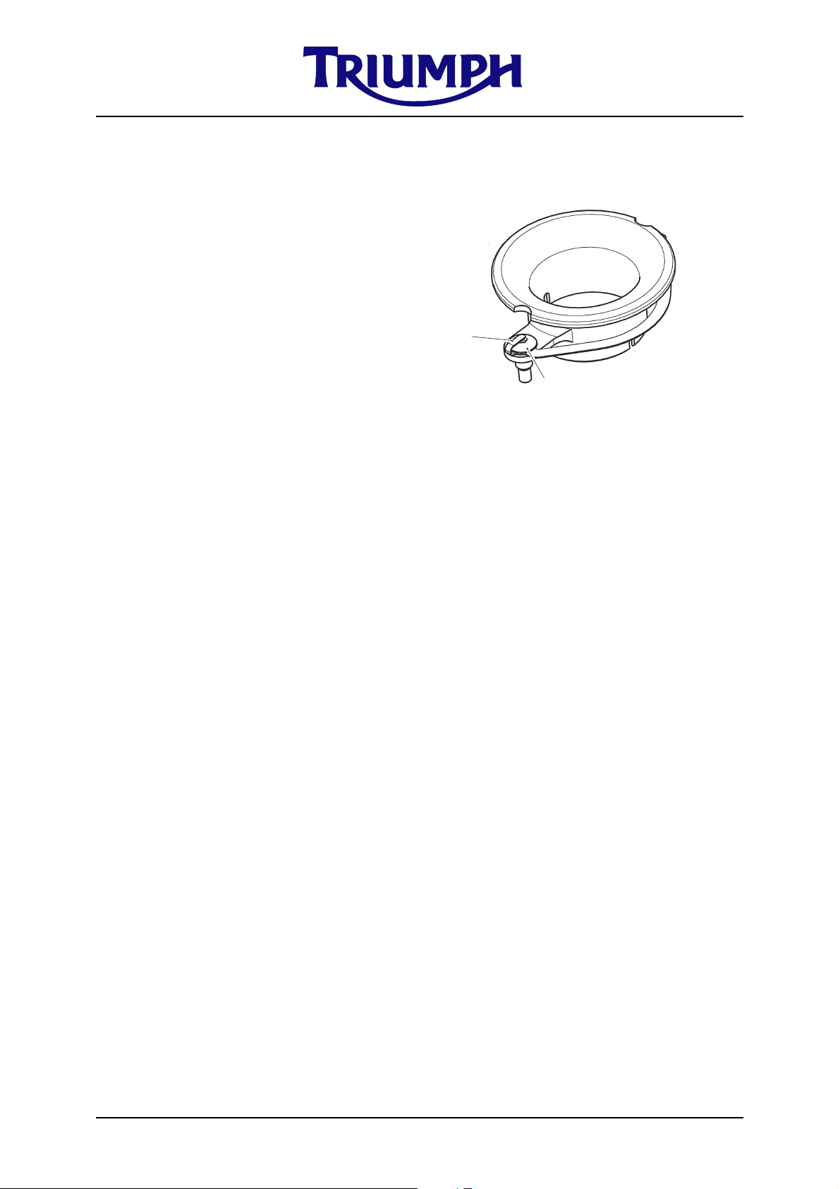
Manual Idle Speed Adjuster Kit
4
3
2
1
Parts supplied - A9618076
Item Description Qty
1 Screw, Manual adjuster 1
2 Spring, compression coil 1
1. Remove the throttle body assembly
following the procedure detailed in the
Daytona 675 service manual.
2. Remove items 3 & 4 shown above from
the assembly.
3. Fit the manual adjuster screw and
compression spring supplied (items 1 &
2).
4. Refit the throttle body assembly
following the procedure detailed in the
Daytona 675 service manual.
5. Adjust the idle speed using the manual
adjuster screw (item 1) as required.
© Triumph Designs Ltd 2007.
Page 25 of 29
Page 26

Race ECU Kit - A9618070
Warning
The race ECU MUST be used with the following race kits; A9618055 Camshaft - inlet,
A9618056 Camshaft - exhaust, A9618057 Camshaft sprocket, A9618058 Valve spring,
A9618063 Air Funnel and A9618071 Race harness.
NOTE
• The race ECU will only work with the race harness A9618071, and production
instruments fitted.
• The race ECU is pre-programmed for use with the following set of race kits;
Inlet & Exhaust camshafts (set to IMOP 104
sprockets), Valves, Air filter, Air Funnels and Arrow Stage 2 exhaust system.
The tune has been developed to suit a compression ratio of 14:1 with
enlarged and polished inlet ports and the exhaust ports modified as
recommended on page 16. However, due to variation between race prepared
engines fuelling adjustments will be required.
• The tune is for a rubber fuel hose only, Triumph Part No. 1240177, it is NOT
suitable for a plastic fuel hose.
• The Air & Fuel ratio should be checked and any adjustments to the fuelling
setting should be made using a third party programmable control unit.
• The rev limit on the race ECU has been increased by 1000rpm over standard.
• The indicated speed shown on the instruments is calibrated for the first gear
pair and housing race kit (A9618066). If the standard gearbox is used, or the
final drive ratio is changed, the indicated speed will be incorrect.
• Idle speed should be set to between 1,500 and 1,800 rpm.
o
/ EMOP 104o with vernier
ECU Malfunction indicator light
• This will flash a sequence of error codes if any faults are present.
• Flash codes have a long flash for the first digit and a short flash for the second
digit. For example; Fault code “32” would be: long, long, long, short, short.
• When a fault has been identified and rectified, the ECU can be cleared by the
following sequence: Full throttle, ignition ON; flick the kill switch off/on/off/
on/off.
Caution
No ECU faults should be present during motorcycle operation. If the motorcycle is used
with ECU faults present it will be operating in default “limp home” mode only which will
produce inconsistent operation.
© Triumph Designs Ltd 2007.
Page 26 of 29
Page 27

Fault Code Table
Flash Code Problem
02 Crank Sensor
33 #1 injector
34 #2 injector
35 #3 injector
37 #1 ignition coil
38 #2 ignition coil
39 #3 ignition coil
06 Throttle position sensor
09 MAP sensor
68 MAP sensor pipe disconnected
12 Coolant sensor
13 Air temperature sensor
14 Atmospheric air pressure sensor
41 Fuel pump
65 EEPROM error
26 5v sensor supply problem
15 Roll over sensor
22 Gear position sensor
24 Ignition switch circuit problem
25 Battery voltage supply problem
43 Cooling fan relay
44 Airflap solenoid
66 Instrument communication error
70 Vehicle speed sensor
67 Main relay
08 Exhaust valve sensor
51 Exhaust valve motor
52 Exhaust valve cables
Continuous
Short Flash
© Triumph Designs Ltd 2007.
Harness or Instruments
Page 27 of 29
Page 28

Race Harness Kit
Parts supplied - A9618071
Item Description Qty
1 Main harness, Race 1
2 Connector, Quick shift 1
NOTE
• The race harness will not work without the Race ECU A9618070.
• The relay and fuse box position has changed on the race harness for ease of access and
maintenance. They are now located alongside the battery, under the seat. Ensure they
are secured in position so they do not suffer from vibration problems.
• The race harness does not support all of the OE equipment, therefore, the following
components can be removed from the motorcycle; Oxygen sensor, Exhaust valve, Idle
speed control, Secondary air injection (SAI), Purge control (California only), Lights and
Air intake flap solenoid. The SAI ports must be blocked off if the system is removed.
The throttle body purge ports must be blocked of before use (California only).
• The race harness still supports the cooling fan and incorporates a relay for the fan. You
may remove the cooling fan but must leave the relay in place.
• The race harness does not support the idle speed control motor and therefore, this may
be removed from the throttle body. It is recommended to use the manual idle speed
adjuster A9618076 to replace the throttle stop screw when using the race harness.
Throttle body balance should be checked if the ISC cam is removed from the throttle
body assembly.
• The race harness is suitable for use with both the standard and race kit Alternator. It is
recommended to always run an Alternator, without it the battery will discharge in a
very short period of time.
• The combination of the race ECU and race harness allows the ability to have ignition
cut for “quick shift”. To use this feature connect a suitable 5V 2mA switch to the
supplied connector and mount the switch in a convenient position. When the switch is
pressed the ignition will cut for 40ms.
• If the quick shift function is not going to be used, leave the harness connector blanked
off to avoid possible short circuits.
© Triumph Designs Ltd 2007.
Page 28 of 29
Page 29

Motorcycle Accessories
Engine Protector Kits
Parts supplied
Clutch cover, Carbon fibre Kit - A9728028
Item Description Qty
1 Clutch cover, Carbon fibre 1
Crank cover, Carbon fibre Kit - A9728029
Item Description Qty
1 Crank cover, Carbon fibre 1
Standard Alternator cover, Carbon fibre Kit - A9728031
Item Description Qty
1 Standard Alternator cover, Carbon fibre 1
Race Alternator cover, Carbon fibre Kit - A9728032
Item Description Qty
1 Race Alternator cover, Carbon fibre 1
1. Apply silicone sealant to the mating
surfaces of the Carbon fibre cover and
corresponding engine cover. The
recommended sealant is “Impact
Adhesive 5255” (or direct equivalent)
which is a high temperature, chemical
and environmental resistant sealant.
NO WARRANTIES ARE PROVIDED FOR THIS RACING KIT. TRIUMPH MOTORCYCLES DOES NOT PROVIDE ANY WARRANTIES FOR
THIS RACING KIT OR FOR ANY OF THE PARTS IN THIS RACING KIT. ALL WARRANTIES, EXPRESS OR IMPLIED, ARE
SPECIFICALLY DISCLAIMED. TRIUMPH MOTORCYCLES DOES NOT PROVIDE ANY WARRANTIES OF MERCHANTABILITY OR
FITNESS FOR A PARTICULAR PURPOSE. IN NO EVENT SHALL TRIUMPH MOTORCYCLES, ITS RELATED COMPANIES OR UNITED
STATES REPRESENTATIVES BE LIABLE FOR ANY ALLEGED BREACH OF WARRANTIES INCLUDING WARRANTIES OF
MERCHANTABILITY OR WARRANTIES OF FITNESS FOR A PARTICULAR PURPOSE. TRIUMPH MOTORCYCLES LTD, ITS RELATED
COMPANIES AND ITS REPRESENTATIVES IN THE UNITED STATES, SPECIFICALLY DISCLAIM ALL LIABILITY ARISING OUT OF
THE USE OF THIS RACING KIT. IN NO EVENT SHALL TRIUMPH MOTORCYCLES LTD, ITS RELATED COMPANIES OR ITS UNITED
STATES REPRESENTATIVES BE LIABLE FOR ANY DAMAGES ARISING OUT OF THE USE OF THIS RACING KIT. THIS MEANS THAT,
IN NO EVENT, SHALL TRIUMPH MOTORCYCLES LTD, ITS RELATED COMPANIES OR ITS UNITED STATES REPRESENTATIVES BE
LIABLE FOR ANY GENERAL, INDIRECT OR CONSEQUENTIAL DAMAGES ARISING OUT OF THE USE OF THIS RACING KIT.
© Triumph Designs Ltd 2007.
Page 29 of 29
 Loading...