

Triumph 1978, 1978 Bonneville 750, 1978 T140E Owner's Handbook Manual
O\N
ClassicBike.biz
ERS
ANDBOOK
FOR
{
....
197
,----NNEVI E
140
PART
U.
L
NO.
.A.
MODEL
715D
99-7007
EDITION
Specialthanksto
Walter
forcontributing
thismanual
T
ClassicBike.biz
OWNER'S HANDBOOK
FOR
BO EVILLE 750
UNIT CONSTRUCTION TWIN
1978
MODEL
© Copyright
AI!
rights reserved. No part of this publication
may be reproduced without permission.
Meriden
Motorcycles Ltd., Meriden Works, Allesley, Covemry, England.
Air filter......... ....... ....
ClassicBike.biz
..........
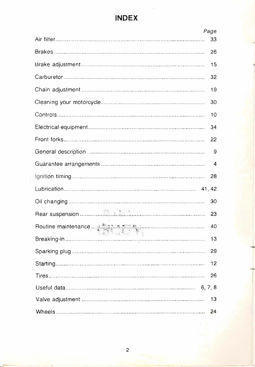
INDEX
............... .......
.....
.......
....
........................ 33
Page
Brakes............
8rake adjustment .
Carburetor .......... .
Chain adjustment.. ................. ............... .......
Cleaning your motorcycle........
Controls......
Electrical equipment....
Fron t forks............... .................................. ....................................... 22
General description
Guarantee arrangements ..... .................
Ignition timing... .................... .................. ...................
Lubrication
Oil changing............................ ....
Rear suspension .............
Routine maintenance
....................
...
...
......
.................
....
...
......................
......
...................
..
..........
... ... ...
.......... ... ............... .
.......
....... ..... ............. ................... ......
...
.......
..
.............................
...
....
..
.............
...
.....................................................................
......
................
...
............................
... ~ ... :
.. ~ ...
..
....
~~'.~~1
;.
...
~.r~'.~
.....
................................
...
.....................
.... .........
....
:....................... .....
..
.....
..... ................. .......
....
.......
...
....
.........
...
..................
..
................
.....
~~;~..
..........
...
.....
..........................
.....
. .
............. .........
....
...
..............
....
..............
...................
.....
..
26
15
....... .....
....
....... ........ 10
.............. 28
.......
.
.... .......
....
. 34
..
........
41,42
....
....
.......
32
19
30
30
23
40
9
4
Breaking-in .............
Sparking plug .........................
Starting.........................
Tires ...............
Useful data.. ........ ...............
Valve adjustment................. ... ........
Wheels
...
...
...................
...
...........................
............................. :........... ........... .............
.......
........ ...............
........
............................................................ 12
...
...................
...
......
.......
..............
...
.......
...........................................................
2
....
.................
...
..... ..................
....
.......
....
................. .......
....
........
........
.....
............. .. 13
...... 13
29
....
.
26
6,
7,
....
24
~
,
8
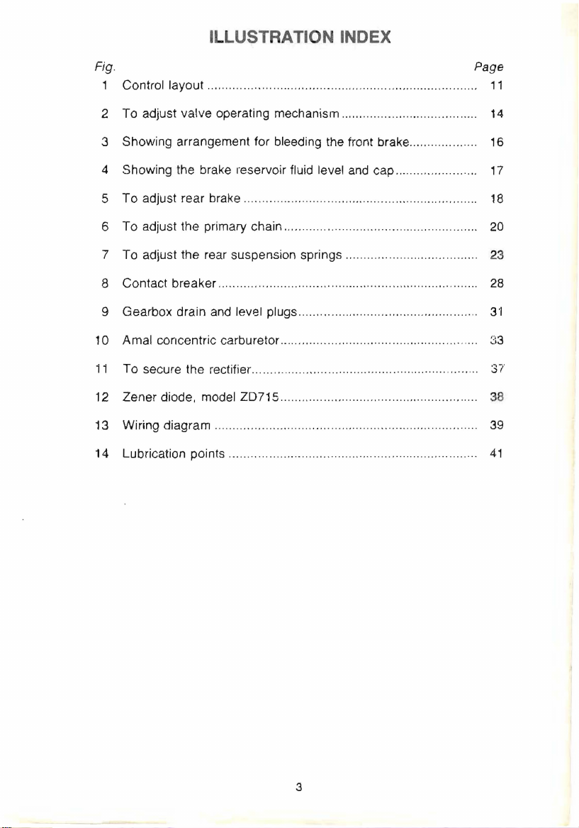
ILLUSTRATION INDEX
ClassicBike.biz
Fig. Page
1 Control layout ..................................
.............
...
...
"'.
.. ....
.....
........
11
2 To adjust valve operating mechanism ...................
3 Showing arrangement for bleeding the front brake....
............
......
4 Showing the brake reservoir fluid level and cap .................
5 To adjust rear brake..
6 To adjust the primary chain......
7 To adjust the rear suspension springs ........... . ..........
8 Contact breaker..................................
9 Gearbox drain and level plugs ...... ......
10 Amal concentric carburetor ................
11
To secure the rectifier............ .......
12
Zener diode, model ZD71S.. ........
13 Wiring diagram......................
14 Lubrication pOints .....
...
.....
....
........ ................... ........................
...
.........
............... .....
..
...............................
.....
...
...
.......... .......... .................
...
...
..................................
......
...
...........................
...
...
........
...
......
...
......... ..
....
................
...
....
.......
.....................................
....
............ .....
.. ..
.. .. ..
......
...
.........
...
.....
...
..... ....
..
........
...........
...
...
....
...
...
14
16
17
18
20
23
28
31
~13
37'
38
39
41
3
INTRODUCTION
ClassicBike.biz
The Owner's Handbook includes all the information that the majority of
owners
there is
having basic
Workshop
we
individual customers.
will require.
available a Workshop Manual but this is intended for those
mechnical knowledge and workshop facilities. To obtain the
Manual order from your local Triumph dealer or distributor as
do
not supply parts or service literature direct from the factory to
If
you require more information for major repairs
Where specialised advice is required beyond the
then you should write to your distributor who will act on our behalf. Unless
the full engine number is quoted it
motorcycle and give a
bearing on the subject
additions or alterati ons to the standard equipment.
Where a gu arantee
who may
be
claims in respect of prop
dealer to his distributor.
The terms of the
dealer.
be
able to provide a replacement to enable your motorcycle to
use
d whilst the defective part
helpful reply. Any information which may have a
should be included, particularly details of any
claim is involved, consul your dealer or distributor
ri
etary components should be forwarded by your
U.S. Triumph guarantee can be obtained from your
is
often difficult to identify the type of
is returned
ability of the dealer ,
to his distr ibutor. Guarantee
4
ClassicBike.biz
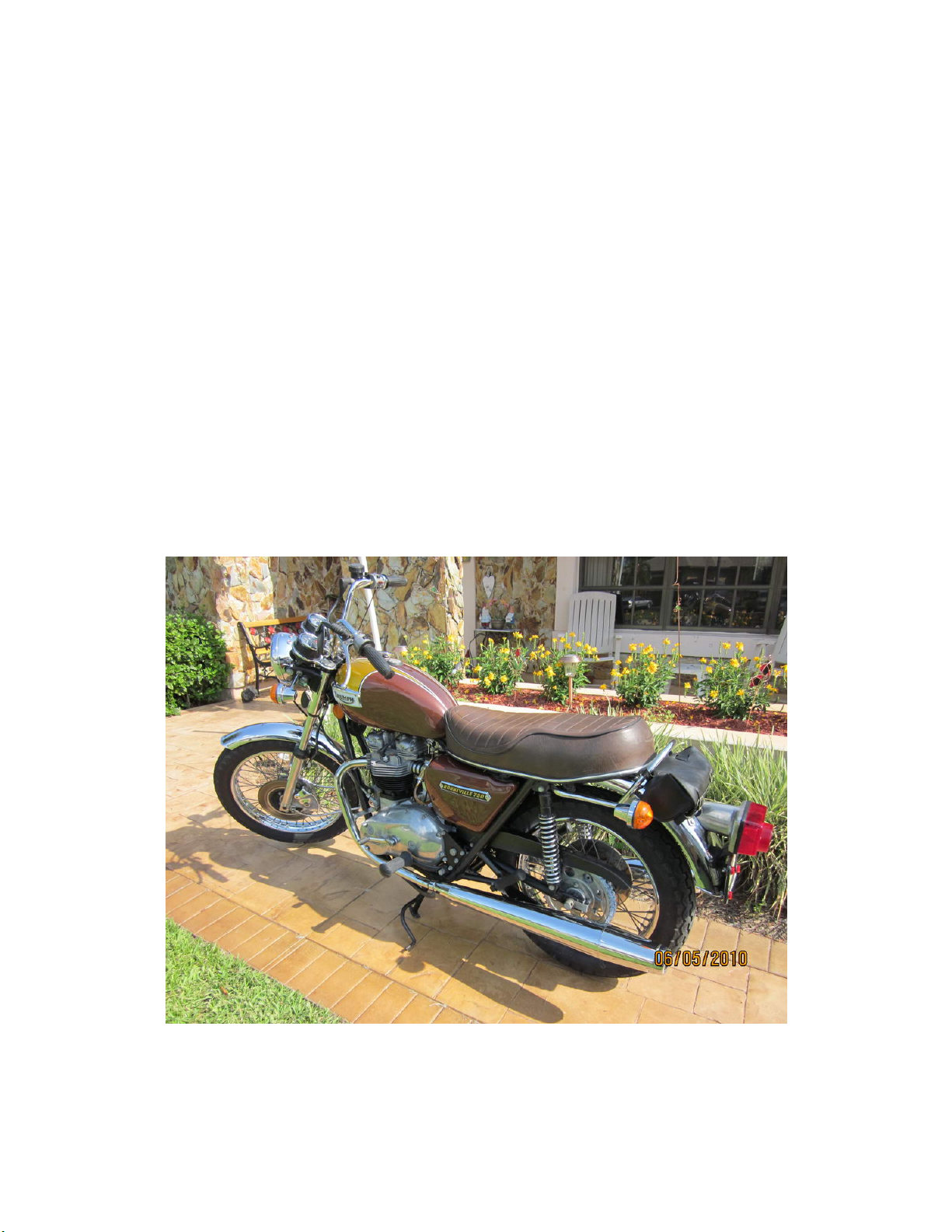
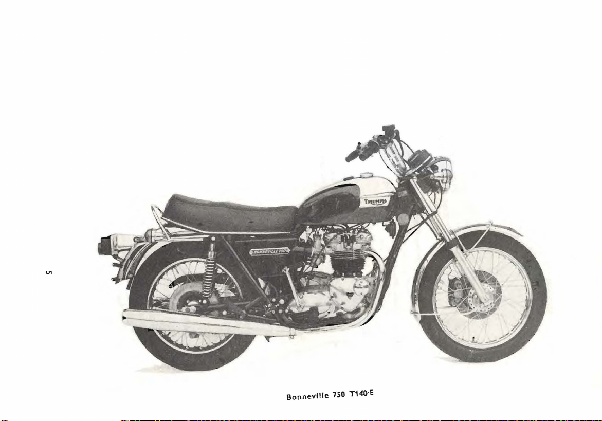
Bonneville
750 T140-E
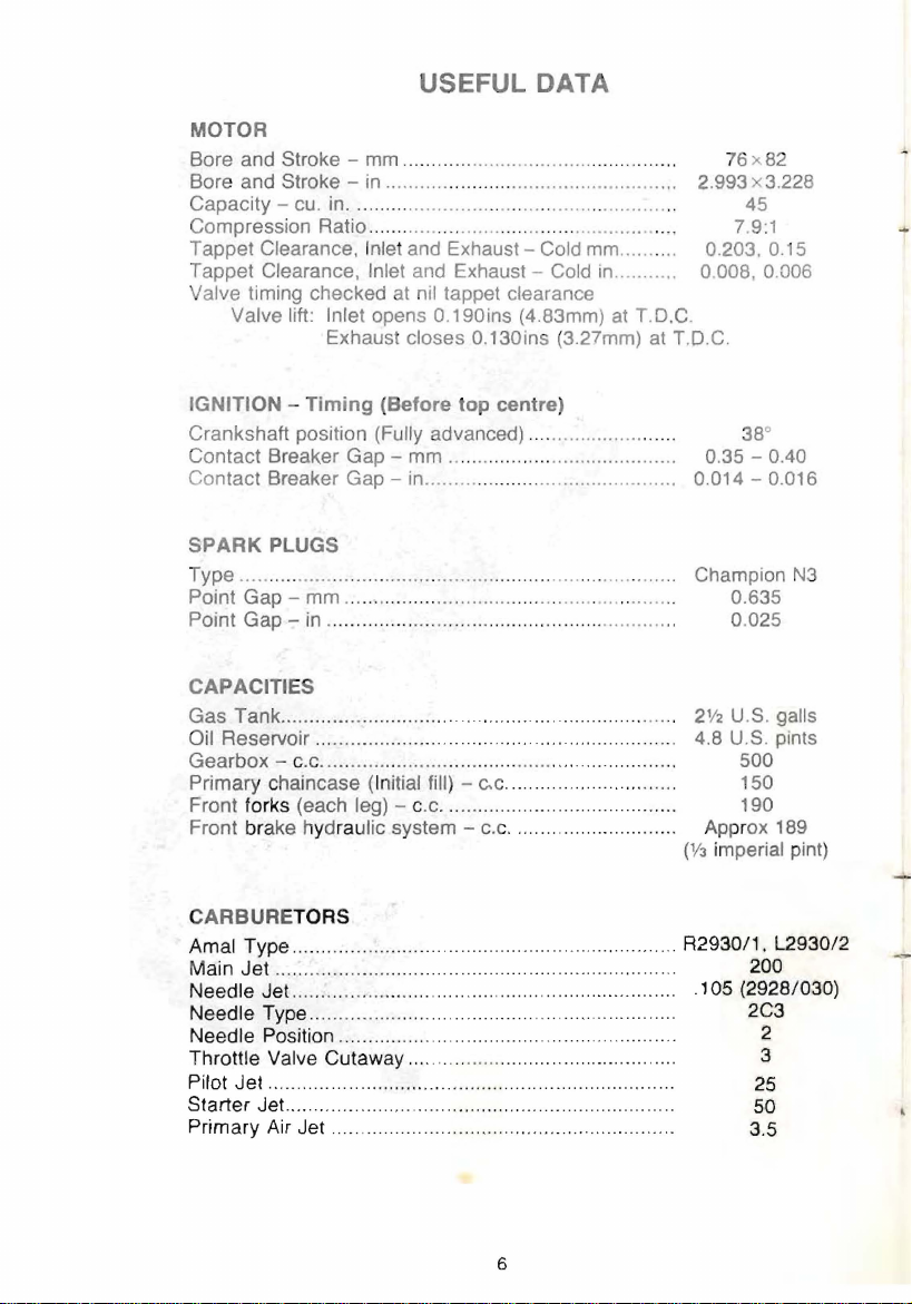
USEFUL DATA
ClassicBike.biz
MOTOR
Bore and Stroke - mm ..............................................
Bore and Stroke -
Capacity - cu. in .....
Compression Ratio .
Tappet Clearance,
Tappet Clearance,
Valve timing checked at nil tappet clearance
Valve lift: Inlet opens 0.190ins (4.83mm) at T.D.C.
in
......................
................
......
..................
Inlet and Exhaust - Cold mm .......
Inlet and Exhaust - Cold
Exhaust closes 0.130ins (3.27mm) at
...
......................
...
.. ..
........................... . .
............................ ,
in
.........
..
..
..
2.993 x3.228
..
.
0.203,0.15
..
o
T.O.C.
76 x
45
7.9:1
OOB,
82
0.006
IGNITION - Timing (Before top centre)
Crankshaft position (Fully advanced) .... ...................... 38
Contact Breaker Gap - mm ........... ............................. 0.35 - 0.40
Contact Breaker Gap - in.............
............................... 0.014 - 0.016
0
SPARK PLUGS
Type ............
Point Gap Point
...............................................
mm ... ....
Gap - in ......................... ...
....
...........................
........
................. Champion
..................
...
..
.......
...........
..
..
0.635
0.025
CAPACITIES
Gas Tank ........................ .......
Reservoir
Oil
Gearbox -c.
Primary
Front forks (each leg) - c.c.
Front brake hydraulic system -
...
... ......... ................
c. ..........
chaincase (Initial fill) - e.c..... .
.. ..
.. ..
.............
................... ...................
...
.. ..
.............
C.
c. ........................... .
.... ....
... .....
....
..............
.. .. ..
......
................ 150
.. ..
...................
..
2V2
U.
... ...
... 4.B U.S. pints
.......
..
Ap
prox 189
(1fJ
imperial pint)
S.
500
190
galls
CARBURETORS
Amal Type ....... ...................... ....................... ...........
Main
Jet....... ...... ................
Needle Jet .........
Needle Type.. .................
Needle Position..............
Throttle Valve Cutaway..........
Pilot Jet
Starter Jet.......... ....... ..... ..............................................
Primary Air
...
.......
............. ............................ ...... ..................
Jet..
........................ .................................. 3.5
..
.......
............ ...............
.. ..... ............
..................................... ........ 2C3
.....
.................. ... ..
.... ..................... .105 (2928/030)
...
....... ................... ...... 3
...
..
"
...
..
....
..
.. ..
...
....... 2
...
R2930/1,
200
L2930/2
25
50
N3
6
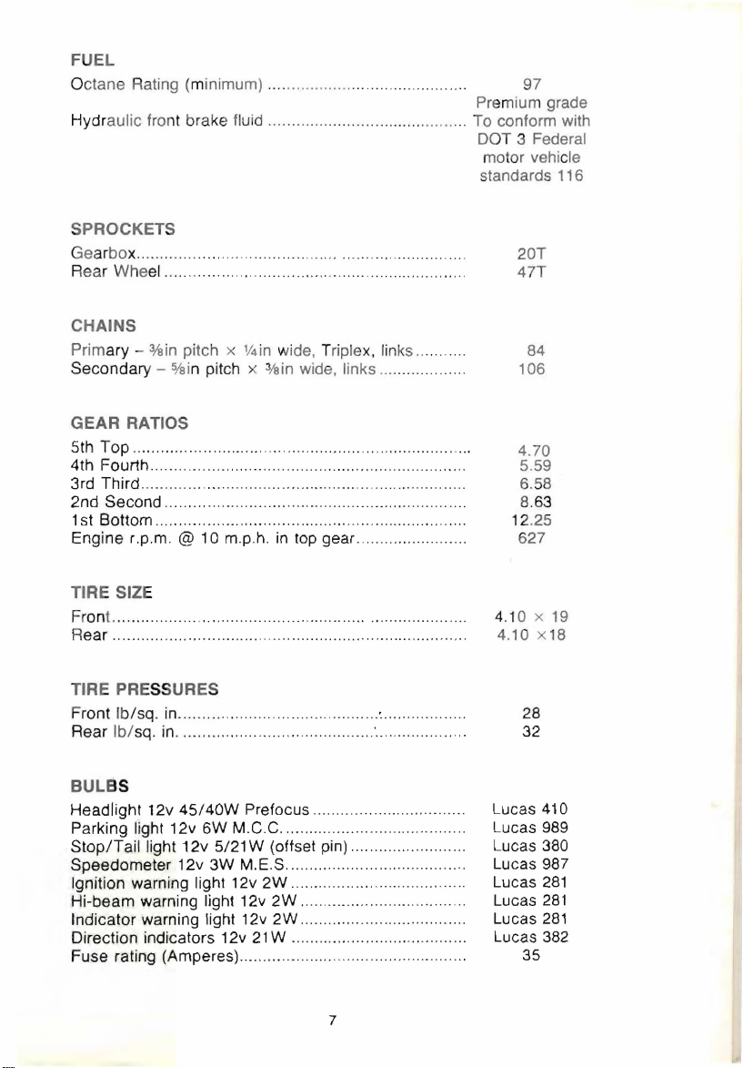
FUEL
ClassicBike.biz
Octane Rating (minimum)
Hydr
aulic fro nt brake fluid .
SPROCKETS
Ge
arbo x........ ..........
Rear
Wheel..
... ...
...........
................
CHAINS
Primary Secondary -o/ai
3/
in
pitch x V4in wide, Triplex, links
a
n pitch x
...
.................. ....
...
...............
..... .. ...... .......
...
........
......................
3/sin
wide, links ....
. ..........
...
.... 97
........................ To conform with
...
...
.........
.........
...
.. .. ..
Premium grade
DOT 3 Federal
motor vehic
standards 116
...
..
.. .. ..
.
..
...... 106
20T
47T
le
84
GEAR
5th
4th Fourth ..........
3rd Third
2nd
1 st Bottom..
Engine r.p.m. @
RATIOS
Top
................................... ...................................
...........
Second .......
...
.... ,........... ..............................
..
............ .... . ...........
..
...
......
..........................................
...................... .
10 m.p.h.
in
top gear
....
TIRE SIZE
Front...............
ear..
........ ...... ....
R
...
..................
.. ....
.......... ......
........ ......................................... 4.10 x
TIRE PRESSURE S
Front /b/sq
Rear
BUL
Headlight 12v
Parking light 12v 6W M.C.C ........
Stop/Tail
Speedometer 12v
Ignition warning light 12v
Hi-beam warning light 12v
Indicator warning light 12v
Direction indicators 12v
Fuse rating (Amperes) ...................
. in.....
..
Ib/
sq.
.............. .........
in
.......................
..................
BS
45/40W
light 12v 5/21 W (offset pin) ....... .......
Prefocus .............
3W
M.E.S ..................................
2W .......
2W
................................
2W
.........
21 W ..
................. ............
.........
.........
...........
.. ..
.. ..
..
.............
.'.........
..............................
..........................
...
..........
......... .................. .
......... 5.59
...
..
.......... .....
.......
.. ..
........ 12.25
....
.. .. .. ..
......
.....
....
.......... 4.10 x 19
....
...........
....
.. ..
...
....
.......
...
.. ..
.... .
...
...
............
...
..
4.70
.... 8.63
..
. 28
...
..
.
..
..
..
..
..
..
..
..
..
..
6.58
627
32
Lucas 410
Lucas 989
Lucas
Lucas 987
Lucas
Lucas
Lucas
Lucas 382
35
18
380
281
281
281
7

OVERALL
ClassicBike.biz
Length -in. ................................
Width - in ....... ..... .........
Seat
Weight -lb. (unladen) ......
DIMENSIONS
height -in. ".......
..
...... " ....................... .............. 33.0
............... ..... ...............
.................
......... ............. .... . .
...
..
....
.. ..
" .................
...
".
..
87.5
31.0
39 5
..:..
8
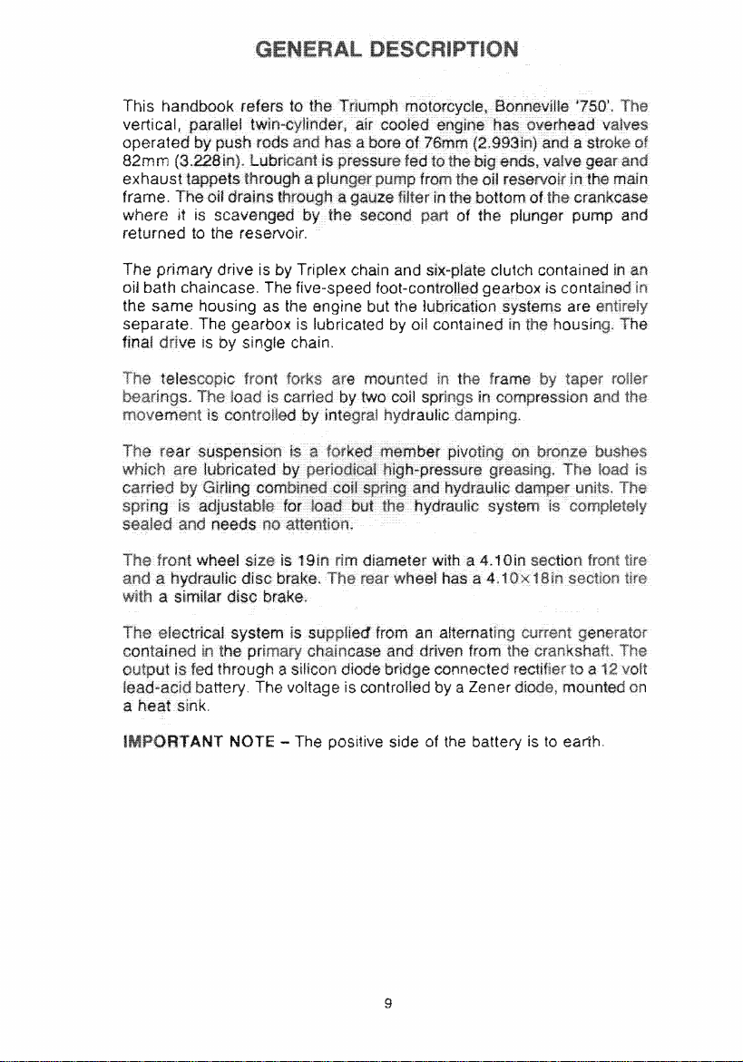
exhaust
ClassicBike.biz
frame.
where
returned
it
is
~f'~:\,U)nrlt:ll1
to
the reservoir.
NOTE - The
DO!:illl\I8
side of the is
9
to
earth.

LAYOUT OF CONTROLS
ClassicBike.biz
Clutch lever - On left handlebar. The clutch couples
the gearbox and rear wheel. Pull the leve towards the handlebar
disengage the clutch.
Kill button - On right handlebar. Depress
off the ignition and remove the key when parking.
Direction indicator switch -
operate the flashing indicators. Move right for right indication and left for
left indicatio n.
Front brake lever -
handlebar
to
apply the front brake.
On
On
right handlebar. Pull he lever toward ' the
to
stop engine. Always switch
left handlebar. Use the switch to
the
engine drive
to
to
Throttle control - Twist the right handlebar grip towards you to increase
to
the engine speed. Twist it away from you
reduce speed.
Horn push - On left handlebar. Press to sound the horn.
Dipper switch - On left handlebar. Use the lever to change the headlight
between
"high" and "Iow" beam.
peedometer - Indicates the speed and regist- 5 total and trip mileage.
To set the trip indicator to zero twist the knob clockwise.
knob as
Tachometer - Indicates the engine speed
lighting
position
second notch for
it
is
a snap fit
in
the speedometer.
in
revolutions per minute.
switch - Operated by a three position switch. From "off"
on
left, move
swi1ch
right to first notch for parking lights
full headlamp.
Do
not PUL the
and
to
Oil pressure warning light - (Red). Frtted into headlamp shell, it illumin-
is
ates as the ignition
running as oil pressure builds up.
beyond tiekover, stop the engine and investigate the cause.
switched
Hi-beam warning light -
selected.
on and should extinguish with the engine
If it fails
(G
reen). Shows as the headlight hi-beam is
to
extingui
sh
with the engine
Direction indicator warning light - (Amber). Illuminates when the
.e
tion indicators are operating.
dire
10
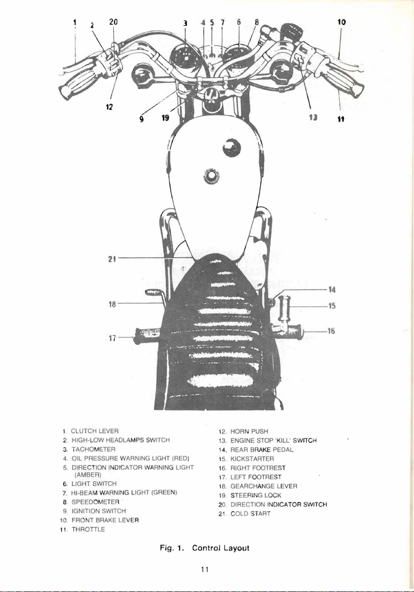
1 CLUTCH
ClassicBike.biz
2.
3.
4. OIL PRESSURE W
5.
6. LIGHT
7.
8
9. IGNITION SWITCH
10
. FRONT BRAKE LE
11 THROTILE
LEVER
HIGH-LOW
TACHOM
DIRECT
(AMBER)
HI-BEAM W
SPEEDOMETER
HEADLAMPS SWITCH
ETER
ION INDICATOR WARNIN
SWITCH
ARNING LI
P.RNING
GHT
VER
LIGHT (RED)
G LIGHT
(GREE
N)
12 HORN
13
1
15 KICKSTARTER
16. RIGHT FOOTREST
17 LEFT FOOTRE
' 8 , GEARCHAN
19
20 DIRECTION INDICATOR
21
PUSH
. ENGINE STOP 'KILL'
4.
REAR B
RAKE
PEDAL
ST
STEERING LOCK
COLD START
GE
SWITCH
LEVER
SWITCH
Fig. 1.
Control
11
Layout
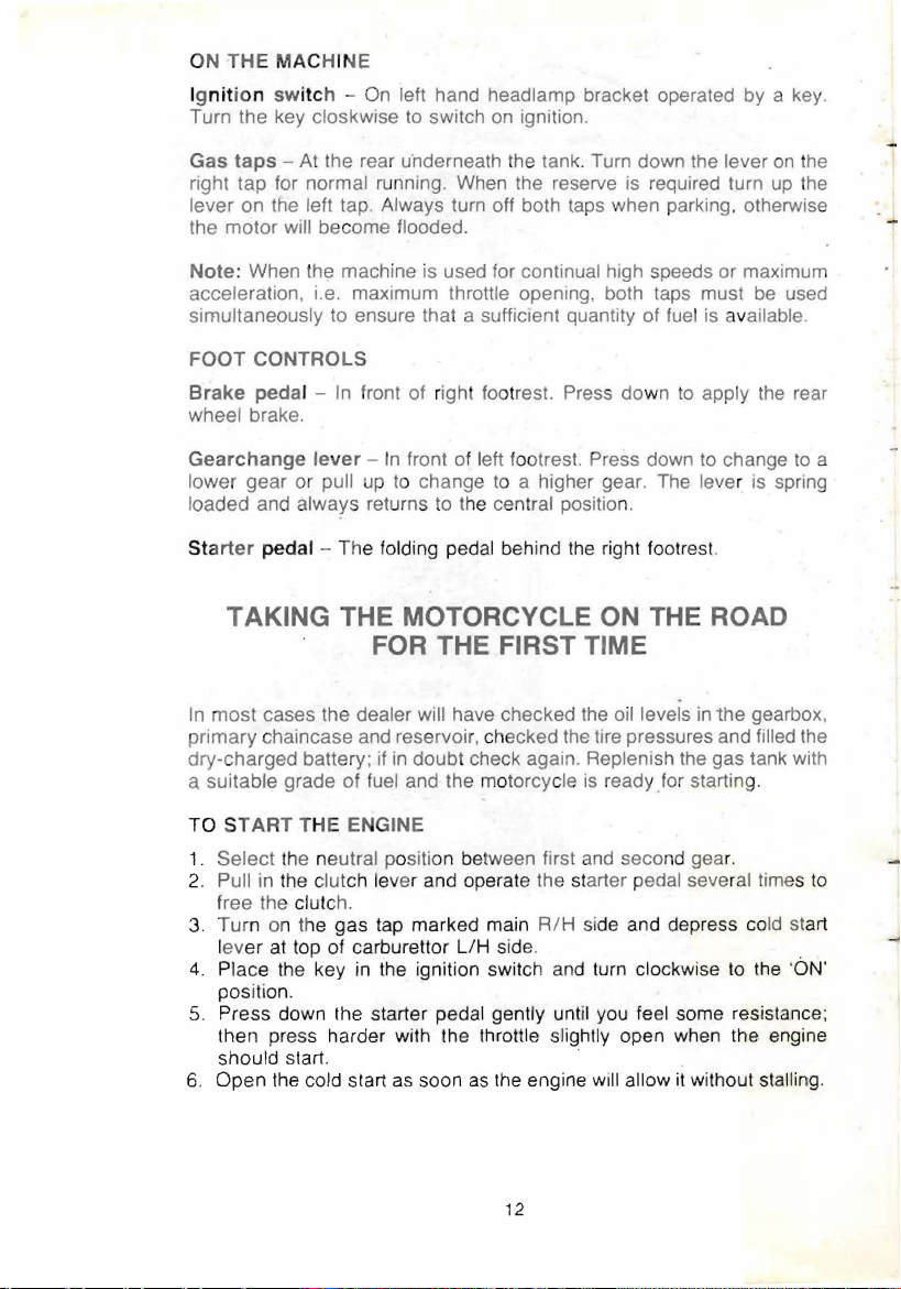
ON
ClassicBike.biz
THE
MACHINE
Ig
ni
tion sw
Turn the key closkwise to switch
Gas
taps
right tap for normal running. When the reserve is required turn up the
lever on the left tap. Always turn off both taps when parking. otherwise
the motor will become flooded.
Note
acceleration, i.e. maximum throttle opening both taps must be used
simultaneously to ensure that a sufficient quantity of fuel
FOOT
Brake
wheel brake.
itc
h -
On
lett hand headlamp bracket operated by a key.
- At the rear underneath the tank. Turn down the lever
: When the machine is used for continual high speeds or maximum
CONTROLS
pedal -
In
front of right footrest. Press down
on
ignition.
to
is
available.
apply
the
on
the
rear
Gearchange
lower gear or pull up to change to a higher gear. The lever is spring
loaded and
St
art
er
lever -In
always returns to t
front of left footrest. Press down
he
central positio
pedal - The folding pedal behind
n.
the
right footrest.
to
change
to
TAKING THE MOTORCYCLE ON THE ROAD
THE FIRST TIME
FOR
In
most
primary chaincase and reservoir,
dry-charged battery;
a suitable grade of fuel and the motorcycle
TO S
1. Select the neutral position between first and seco
2.
3. Turn
4.
5. Press down the starter pedal
6.
cases the dealer will have checked the oil levels
if
in
doubt check again. Replenish the gas tank with
TART
THE ENGINE
Pull
in
the clutch lever and operate the starter pedal sever
free the clutc
on
lev
er
Place the key
position.
then press harder with the throttle
should start. .
Open
h.
the
gas
tap marked main
at top of carburettor
the cold start as soon
in
the ignition switc h and turn clockwise
ch
ecked the tire pressures and filled the
is
R/H side and depress co
LlH
side.
genlly until you feel some resistance;
sl/ightly open when the engine
as
the engine will allow it without
ready for starting.
nd
in
the
gear.
gearbox,
al
times
ld start
to
the
staIHn:g.
-ON'
a
to
12
RUNNING IN YOUR NEW MOTORCYCLE
ClassicBike.biz
Al
though the new parts are machined
rt
moving pa
'·b roken~in".
s need to mate with ea
At a low constant speed this would take a considerable
age, therefore the ideal method of
as
accurately as possible the
ch
other or become what is known
breaking~in
gressively the load and length of time the load
machines
opening
throttle opening, even
will travel at 50m.p.h. (80Km/h) with only a small throttle
on
a level road without harm when new but any use of a large
in
a lower gear, other than for a very short time
may cause damage .
is
to increase pro-
is
maintained. These
as
mile~
Change gear frequently
neither pulling hard
extra use of the gearbox helps
difficult
to
quote a set mileage but provided that the running-in
intelligently it should
so
in
that the engine is always working easily,
a high gear nor revolving fast
to
run-in
all the transmission parts. It
be
possible
to use
maximum performance after
in
a low gear. The
is
done
1,500 miles (2.500Km). Whenever the maximum performance is used
is a good plan to snap shut the throttle for a moment occasionally
sucks a certain amount of
oil up the cylinders.
as
this
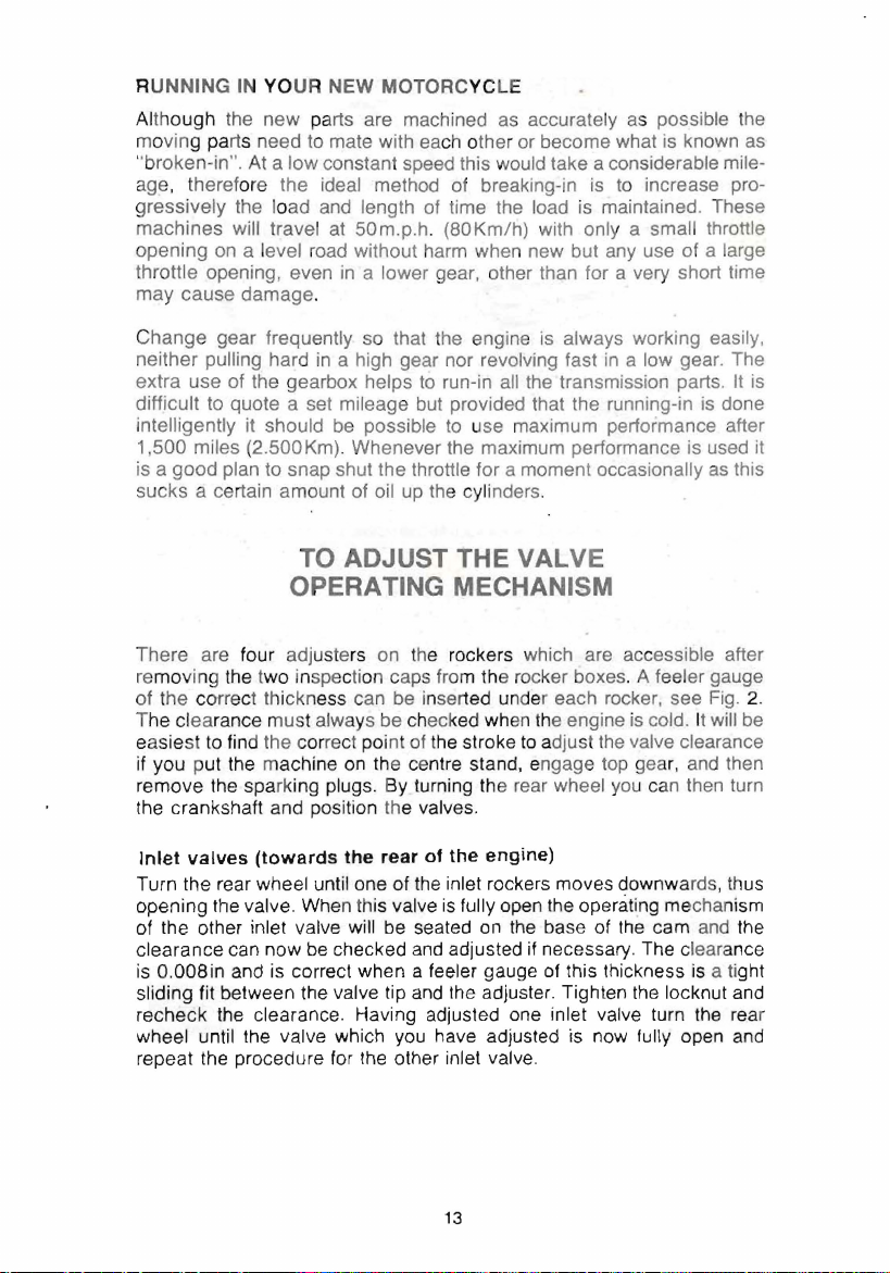
TO ADJUST THE VALVE
OPERATING MECHANISM
There are four adjuste
re
moving the two inspection ca
of the correct thickness can be inserted u
The clearance must always be chec
easiest
to
find the correct
if you put the machine
remove the spa rking plugs. By turning
the crankshaft and position the valves.
Inlet
valves
(towards
Turn the rear wheel until one of the inlet rockers moves downwards, thus
opening
the
valve. When this
of the other inlet valve
clearance can now
is
0.008in and is correct when a feeler gauge of this thickness
sliding fit between the valve tip and the adjuster. Tighten the locknut and
recheck
the
clearance. Having adjusted one inlet valve turn
wheel until the valve which you have adjusted is now
repeat the procedure
rs
on the rockers which are accessible after
ps fro
m the rocker boxes. A feeler gauge
nd
er each roc
ked when the engine
pOi
nt of t
he
stroke
to
adjust t
on the centre stand, engage top gea
th
e rear wheel you can then turn
the
rear
of
the
engine)
valve
is
will be seated
be
checked and adjusted
for
the other inlet valve.
fully open the operating mechanism
on
the
base of
if
necessary. The clearance
ker,
see
is
cold. It will be
he
valve clearance
r,
and then
the
cam and the
is a ti
the
fully open and
Fig. 2.
ght
rear
is
it
13
 Loading...