

Page 1
ars
Page 2
Complete Service Manuals published
by
Robert Bentley, Inc.
Volkswagen Beetle and Karmann Ghia Official Service Manual Type 1, Model Years
1966-1969. Volkswagen of America, Inc.
Volkswagen Super Beetle, Beetle and Karmann Ghia Official Service Manual Type 1,
Model Years 1970-1976. Volkswagen of America, Inc.
Volkswagen Station
WagonIBus Official Service Manual Type 2, Model Years 1968- 1976.
Volkswagen of America, Inc.
Volkswagen
Fastback and Squareback Official
Service Manual Type 3, Model Years
1968- 1973. Volkswagen of America, Inc.
Capri Complete Service Manual,
Model Years
1970- 1974. Robert Bentley, Inc.
Complete Official Triumph TR2
&
TR3,1953- 196 1-includes Driver's Instruction Book
and Service Instruction Manual. British Leyland Motors
Complete Official Triumph TR4
&
TR4A, 196
1
-
1968-includes Driver's Handbook,
Workshop Manual, Competition Preparation Manual. British Leyland Motors
Complete Official Triumph GT6, GT6
+
Mk 111, 1967- 1973-includes Driver's Hand-
book and Workshop Manual. British Leyland Motors
Complete Official Triumph TR6
&
TR250,1967- 1975-includes Driver's Handbook and
Workshop Manual. British Leyland Motors
Complete Official Triumph Spitfire Mk 111, Mk IV
&
15 00,1968 - 1976-includes Driver's
Handbook and Workshop Manual. British Leyland Motors
MG Workshop Manual: Complete Tuning and Maintenance Por All Models from
"M"
Type to TF 1500. W.E. Blower
Complete Official MGB, Model Years
1962- 1974-includes Driver's Handbook, Work-
shop
Manual, Special Tuning Manual. British Leyland Motors
Complete Official Jaguar "E-includes Driver's Handbook, Workshop Manual, Special
Tuning Manual. British Leyland Motors
Complete Official
948cc
&
1098cc SpriteIMidget-includes Driver's Handbook, Work-
shop Manual, Special Tuning Manual. British Motor Corp.
Complete Official
1275cc SpriteIMidget, 1967- 1974-includes Driver's Handbook,
Workshop Manual, Emission Control
Supplement. British Leyland Motors
Page 3
del
Years
Comprising
the
official
driver's instruct ion book
service instruct ion manual
Robert Bentley,
Inc.
872
Massachusetts Avenue
Cam bridge, Mass.
02139
Page 4

Library of Congress Catalog Card Number 75-42893
ISBN 0-8376-0125-8
Manufactured in the United States of America
Copyright
Q
1976 Robert Bentley, Inc.
All rights in this book are reserved.
No responsibility accepted for the accuracy of the contents.
Page 5
Taken as a whole, the Triumph TR2s and TR3s represent
one of the most successful sports car designs in history; so successful that, by the early nineteen-sixties, they had helped to
make Standard Triumph the second-best selling imported car
marque in the United States. During the late nineteen-fifties
and early nineteen-sixties, countless fledgling race drivers
gained their early experience in these machines. Among them
was three-time World Champion Jim
Clark, who owned one of
the first-if not the very first-TR3 in
Scotland.
Today, in the nineteen-seventies,
TR2s and TR3s are as
eagerly sought after as they were twenty years ago when the
cars were
in production. This should not be surprising since
there has never been a time during those twenty years when
TR2s and TR3s were not proving their worth. In 1965, fully ten
years after the TR2 was discontinued and almost five years
after the last TR3 had been built, the cars remained highly
competitive in racing. In that year, the Sports Car Club of
America's U.S. F-Production Championship was won by
Brian Fuerstenau in a TR3-with Lee Midgely's TR2 solidly in
second place.
Wise collectors began to acquire
TR2s and TR3s even before
their long and successful history had been written on the race
track.
(As recently as 1975 a TR3 made
the field for The Cham-
pion Spark Plug Road
~acin~ Classic-an event that deter-
mines the ultimate
standings in
U.S. amateur road racing.) In
1970, at a time when the newest TR3 was on the verge of
becoming a ten-year-old relic, well-maintained examples of its
predecessor, the TR2, were already being purchased by collectors for more than the cars had cost when new. The prices of
fully restored
TR3s have since begun to follow suit and will un-
doubtedly
continue to rise as fewer examples of the type
become
available on the open market.
This is as it should be; the
TIP2 and TR3 are landmarks in
the
evolution of the sports car. Before the TR2 arrived on the
automotive scene, enthusiasts of limited means had very few
cars from which to choose. The TR3 was a windfall particularly to sports car-starved Americans who, in buying a Triumph,
could acquire 100-mph capability at a cost little greater than
that required to obtain an 80-mph
MG.TF.
Because the value of TR2 and TR3 sports cars is increasing,
it is impossible to overstate the importance of correct
maintenance and repair.
Unfortunately, original workshop
manuals and owner's manuals have, since the assimilation of
Standard Triumph by British Leyland Motors, become virtual-
ly impossible to obtain. Indeed, original books are now
collec-
.
.
tor's items in their own right. No vintage Triumph enthusiast
would choose to risk one by placing it on an oil-stained
workbench or on a garage floor! A new, readily available and
easily replaceable manual that duplicates the orginal manuals'
This Manual has been compiled in order to meet that need,
thereby supplying complete, accurate, and comprehensive
maintenance and repair data to both car owners and professional mechanics. The
Driver's Instruction Book,
which comprises the first part of this Manual, is similar to the handbook
provided with every new TR3. The
Service Instruction Manual,
which comprises the second-and largest-portion of this
Manual, is the official factory manual and was originally intended for use by dealer service departments. Owners of
TR3s
and the so-called TR3A or TR3B model will find it informative
to read the Foreword to the TR3 Supplement, which appears
on page
419.
Assembly work on small, highly-tuned machines such as the
Triumph sports
cars must be carried out with greater precision
than is commonly practiced on large American cars. Particular
emphasis must be given to the proper use of torque wrenches
and to strict adherence to the tightening torque specifications
which are given in this Manual. A fastener that is too tight can
be worse than one that is too loose-especially on a lightweight
sports car. Stretched or broken bolts and distorted parts, which
result from overtightening by musclebound mechanics, become
a serious concern where the precision fitting of light alloy and
thin-wall iron castings is involved.
The importance of cleanliness cannot be overemphasized.
Under no circumstances should an engine or gearbox be
repaired on the ground or on a garage floor. Thoroughly clean
the exteriors of major components prior to disassembly in
order to keep road dirt and other grime out of the working
parts. No more than a pinch of abrasive dust in a gearbox can
cause rapid failure of the synchronizers and bearings.
During the final assembly of an engine or gearbox, the
cleaned parts should be laid out on a clean workbench that has
been covered with clean sheets of new cardboard or wrapping
paper. The engine or gearbox itself, if not mounted on a special
stand, should likewise be placed on a clean workbench. Sandpapering, valve grinding, or the use of bench grinders should
not be permitted near the area where final assembly is taking
place. If assembly cannot be completed in a day, enclose the
partially-assembled engine or gearbox in a large plastic
bag-such as a new trash bag or a dry cleaner's garment return
bag-so that dust and dirt will be excluded until assembly
work resumes.
By observing these precautions during the maintenance,
repair, or restoration of your TR2 or TR3, you will be preserving the value and the life of a car that is rapidly becoming one
of the classics among post-World War
I1
sports cars. If at any
time you lack the skills, special equipment, tools, or workshop
facilities for making repairs as they are described in this
Manual, we suggest you leave such repairs to an Authorized
contents is clearly needed.
Dealer or other qualified shop.
Page 6
Note on the Table of Contents
Both the
Driver's Instruction
Book
and the
Service In-
struction Manual
are presented here exactly as originally
published by the Standard Motor Co.-including the
original page numbers. (The small numbers in the
center
at the bottom of each page are the original page
numbers.) We
have added the large, bold page numbers
at the lower outside margin of each page.
It is these large
numbers that are referred to in the Table of Contents
starting on the next page.
Page 7
Contents
...............................................
Preface
5
1
OFFICIAL TRIUMPH TR2 & TR3 DRIVER'S INSTRUCTION BOOK
GENERAL DATA
..........................................................
12
Spare parts service, Licence data, General specification,
Road speed data
MANAGEMENT OF THE CAR
......................................
16
Controls, switches and instruments (clutch, bonnet locks,
choke control, gear lever, handbrake, radio controls,
overdrive control, petrol tap, seat adjustment, screen
washer, scuttle ventilator, brake light, direction indicators, head, tail and parking lamps, horn, ignition,
panel lights, starter motor, windscreen (windshield)
wiper, heater switch, ammeter, fuel gauge, oil pressure
gauge, speedometer, tachometer, ignition warning light,
water temperature gauge), Driving the car (to start the
engine,
driv~ng, new engines)
GENERAL UPKEEP
..........................................................
21
Regular inspection, Cooling system (filling, draining,
anti-freeze mixtures), Lubrication (engine, gearbox, rear
axle, brake and clutch operation, road wheel hubs, front
suspension and steering, propeller shaft, rear road
springs, hydraulic dampers, hinges, controls, door
Locks),
Tires (front wheel alignment, the jack)
BODYWORK
.....................................................................
33
Door adjustment, Soft top stowage, Soft top fasteners,
Spare wheel and tool stowage
RUNNING ADJUSTMENTS
............................................
35
Engine (decarbonizing and valve grinding, cylinder head
nuts, valve-rocker clearances, ignition timing, valve tim-
ing, sparking plugs, carburetors, fuel pump), Clutch,
Brakes (adjustment of brake shoes-lockheed brakes,
Girling brakes, handbrake adjustment, bleeding the
brake and clutch hydraulic system), Propeller shaft,
Hydraulic dampers, Loose bolts and nuts
ELECTRICAL SYSTEM
.................................................
46
Ignition, Battery, Dynamo (belt tightness), Starter motor
(cleaning and lubrication), Control box, Fuses, Lamps
(head lamps-bulb replacement, lamp alignment, to
check and adjust alignment, parking lamps (front) and
direction indicator flashing lamps, tail and
dnection m-
dicator flashing lamps, number plate
illuminator and
brake lamp, ignition warning light, direction indicator
warning light, high beam warning light, instrument panel
lights), Windscreen (windshield) wiper, Direction in-
dicators,
Windtone horns, Electrical component
specification chart
.......................................................
OPTIONAL EXTRAS 52
Radio, Heater, Overdrive (operation, lubrication, draining), Wire wheels
-,
RECOMMENDED LUBRICANTS
..............................
.....
57
Recommended lubricants chart-overseas, British Isles
OFFICIAL TRIUMPH TR2 & TR3 SERVICE INSTRUCTION MANUAL
GENERAL DATA
.......................................................
63
Chassis specification, Body dimensions, Car
we~ght, Tire
sizes and pressure, Water capacity, Oil
capacity, Petrol,
Body specification, Spire speed nuts (general notes,
description, tightening torques), Commission number,
Body number, Engine number, Gearbox number, Rear
axle number, Recommended lubricants (British Isles,
overseas countries), Lubrication chart, Nut tightening
torques, Fractional and metrical equivalents chart,
Stan-
C.
dard measure and metric equivalents
ENGINE
...........................................................................
81
Dimensions and tolerances, General description (engine,
cylinder block,
cyl~nder sleeves, connecting rods, aeroflex
compensating
pistons, crankshaft, valves, camshaft,
cooling system, fuel system, Hobourn-Eaton double
rotor oil pump, coil ignition, engine mountings, flywheel,
to fit replacement starter ring gear, crankcase
ventlla-
tion), Engine
lubrication, Oil pump, Crankshaft and
main bearings (main bearing clearance, crankshaft end
float), Connecting rod bearings, Piston assembly and
cylinder sleeves, Figure of eight joints, Camshaft and
timing gears, To remove camshaft, Refitting camshaft,
To set valve clearances, To set valve timing in the
absence of timing wheel markings, Ignition and dis-
tributor timing, To decarbonize, Valve grinding,
D.
Removal of carbon, Low compression Kit-part No.
502227, "Purolator Micronic" oil
filter-type,l7F.5102,
Removal of engine and gearbox as a unit, D~smantling
engine, Re-assembly
of
engme, Ignition system (notes on
sparking plugs), List
of distributors being serviced,
Engine noises (main bearing knock, crankshaft end float,
big end bearing knock, small end knocks, piston knock,
noisy valve rockers or tappets, ignition knock (pinking),
back firing into carburetor, excessive oil consumption,
low oil pressure, high oil pressure), Fault location chart
........................................................
COOLING SYSTEM 141
Description, To drain cooling system, Fan belt adjustment, Thermostat, To remove thermostat housing, To
replace thermostat housing, To remove thermostat only,
To replace thermostat, Testing thermostat, Water
temperature gauge, To test water temperature gauge,
Radiator, To remove radiator, To replace radiator, Flexible hose connections, Water pump assembly, To remove
water pump bearing housing, To replace water pump
bearing housing, To dismantle bearing housing assembly, To assemble bearing housing assembly,
Recut-
ting water pump sealing
face, To remove water pump
body, To replace water pump body, Fan assembly, To
remove fan assembly from engine unit, To fit fan assembly to engine unit, To assemble fan for balancing,
Anti-freeze precautions, Service diagnosis chart
.........................................................................
CLUTCH 155
General data, Tool data, Clutch operation, Twin bore
master cylinder, Clutch slave cylinder, Clutch operating
shaft, Release bearing, Cover assembly, Driven plate assembly, Maintenance, Bleeding hydraulic system,
Greas-
Page 8
ing clutch operating shaft, Adjusting clutch, Adjusting
master cylinder, Adjusting slave cylinder, To remove
flexible hose, To fit flexible hose, Removal of slave
cylinder (with fork-rod assembly), To replace slave
cylinder, Dismantling slave cylinder, Assembly of slave
cylinder, To remove release bearing and clutch operating
shaft, To replace clutch operating shaft and release bearing, Removal of clutch from flywheel with gearbox
removed, Replacement of clutch to flywheel, Dismantling cover assembly using Churchill fixture No.
99A, As-
sembly of
cover plate assembly using Churchill fixture
No.
99A, Dismantling cover assembly without
Churchill
fixture, To assemble cover assembly without Churchill
fixture, Inspection of cover assembly, Adjusting release
levers, Condition of clutch facings, Reconditioning of
driven plate assembly, Service diagnosis chart
.....................................................................
GEARBOX 173
Dimensions and tolerances, Operation, Ratios, Bearings,
Mounting, Oil capacity, Nut and bolt data and tightening torques, To remove gearbox leaving engine in position, To replace gearbox, To dismantle, To assemble, To
dismantle top cover assembly, To assemble, Installation
of overdrive (dismantling, assembly of gearbox, fitting
overdrive unit, valve checking, valve adjustment, fitting
isolator switch, operating switch), Supplementary instructions for incorporating overdrive on "second" and
"third" gears (overdrive unit, gearbox top cover assembly)
REAR AXLE
....................................................................
205
General discription, To remove hubs, To replace hubs,
To remove hubs
(center lock type), To replace hubs
(center lock type), To remove axle shaft, To replace axle
shaft, To remove axle, To replace axle, To dismantle, To
re-assemble,
Service diagnosis
......................
FRONT SUSPENSION AND STEERING 225
Front suspension data, Description, Maintenance, Front
wheel alignment, To adjust front wheel alignment, Steer-
ing lock stops, To set steering lock stops, To remove
front hub and stub axle, To replace front hub and stub
axle, To remove front shock absorber, To fit shock absorber, To remove front road spring, To fit road spring,
To remove and dismantle front suspension unit, To assemble and replace front suspension unit, Steering, Type
and description, Maintenance, Adjustment of steering
box, To remove control head from steering wheel, To fit
control head and stator tube to steering wheel, To
remove steering wheel, To fit steering wheel, To remove
steering unit, To fit steering unit, To dismantle steering
unit, To assemble steering unit, Removal and replacement of drop arm, To remove idler unit, To fit idler unit,
Steering column bracing, Telescopic (adjustable) steering
unit (description, steering unit, steering wheel, control
head), To fit telescopic steering unit and steering wheel,
To remove telescopic steering wheel and steering unit, To
remove control head from
center of telescopic steering
wheel, To fit control head and stator tube
to telescopic
steering wheel, Steering stiffness, Assessment of accidental damage
..............
ROAD SPRINGS AND SHOCK ABSORBERS
255
Front spring (description, maintenance, to remove or
replace), Rear road springs (description, maintenance, to
remove rear road spring, to fit, rear road spring
overhaul, to dismantle, to assemble), Front shock absorber (description, maintenance, operation of telescopic
shock absorber, to remove or replace front shock absorber), Rear shock absorber (description, maintenance,
valve operation, to remove rear shock absorber, to fit
rear shock absorber)
FRAME UNIT
..................................................................
265
Description, Assessment of accidental damage, preparation of car, Checking side members for twist, Checking
side members for cradling, Checking side members for
squareness, Checking side members for bowing
PROPELLER SHAFT
......................................................
275
Description, Lubrication, Maintenance instructions,
Removal of propeller shaft, To dismantle propeller shaft,
To examine and check for wear, To assemble, To fit
propeller shaft
L.
WHEELS AND TIRES
..................................................
281
Construction of tire, Tire pressures, Repair of injuries,
Factors affecting tire life and performance (inflation
pressures, effect of temperature, speed, braking, climatic
conditions, road surface, impact fractures), Special types
of irregular tread wear ("heel and toe" or "saw tooth"
wear, "spotty" wear), Wheel alignment and its association with road camber (precautions when measuring
wheel alignment), Camber, castor and king pin inclination, Tire and wheel balance (static balance, dynamic
balance), Changing position of tires, Pressed steel wheels,
Wire wheels (to remove, to replace, examination, wheel
building)
...................................
ELECTRICAL EQUIPMENT .....297
Batteries-models GTW7A/2, GTW9A12, GT9A/2,
and GTZ9A/2 (routing maintenance, service data, servicing, preparing new unfilled, uncharged
batteries for
service, preparing GTZ "dry-charged" batteries for service, battery cable connectors), Generator-model C.39
PV/2 (general, routine maintenance, performance data,
servicing), Starting motor-model
M418G (outboard
drive)
(general, routine maintenance,
performance data,
servicing, fault diagnosis chart), Starting motor drive
(general, routine maintenance, construction, dismantling, re-assembly), Distributor-model DM2 (general,
routine maintenance, design data, servicing),
Headlamps-model F700
MK/VI (general description,
bulb
replacement, setting,
renewal of light unit), Control
box-model
RB106-1 (general, setting data, servicing),
Windscreen
(windshield)
wiper
CRT15 (general, flashing
light direction
indicators), Electric
windtone horns--
models
WT614 and WT618 (general-adjustment, inter-
nal faults, both
horns fail to operate, one horn fails to
operate), Wiring diagram, Control box-model
RB106-2
(general, setting data, servicing)
.................................
....................................
N.
BODY
..
339
Body mounting points, To remove body, To fit body,
Battery box drain, To remove and dismantle front
bumper, To fit front bumpers, To remove rear
overriders and brackets, To fit rear over-riders, To remove
front wing, To fit front wing, To remove
rear wing, To fit
rear wing, To remove bonnet lid, To fit bonnet lid, To
remove front apron, To fit front apron, Adjustment of
bonnet locks, To remove windscreen (windshield), To fit
windscreen (windshield), To fit aero-windscreen, To
remove door, To
fit door, Front door water sealing, To
remove door lock, To fit door lock,
Removal of gearbox
tunnel, To fit gearbox tunnel, To remove hood and fit-
tings, To fit hood and fittings, Water sealing of hood
seams, Adjustment of side curtains, To prepare car for
fiberglass hard top canopy, To fit fiberglass hard top
canopy, To remove fiberglass hard top canopy, To
remove luggage boot lid, To fit luggage boot lid, To dismantle spare wheel lid, To assemble spare wheel lid, To
fit Smiths circular heater
C.H.S. 92014
FUEL SYSTEM
................................................................
357
Data and description (tank capacity, petrol stop tap,
petrol pump, carburetors, air cleaners), To remove petrol
tank, To fit petrol tank, Petrol gauge, Precaution when
carrying out tests, To test dash meter, To test tank unit,
Fuel gauge fault location chart, To remove flexible petrol
feed pipe, To fit flexible petrol feed hose, Petrol stop tap,
To remove petrol stop tap, To fit petrol stop tap, Servicing petrol stop tap, To dismantle petrol stop tap, To assemble petrol stop tap, AC fuel pump type
"UP, Petrol
pump oil seal, To clean pump filter, Testing while on
engine, To remove
petrol pump from engine, To fit
petrol pump to engine, To dismantle
petrol pump, To as-
semble petrol pump, Inspection of parts,
AC
air cleaners,
To remove air cleaners, To fit air cleaners to carburetors,
Servicing air cleaners, Disconnection of carburetor controls, To remove accelerator pedal, right hand side, To fit
accelerator pedal, right hand side, To remove accelerator
pedal, left hand side, To fit accelerator pedal, left hand
side, To remove carburetor from manifold, To fit
carburetors to manifold, S.U. carburetor (description, construction), Throttle
and mixture control interconnection,
Effect of altitude and climatic extremes on standard tuning, Carburetor jet needles, To remove jet needle, To fit
Page 9
needle, Centralization of jet, To assemble carburetor(s),
To adjust fuel level in float chamber,
Carburetor tuning,
Carburetor defects (pistons sticking, eccentricity of jet
and needle, flooding from float chamber or mouth of jet,
leakage from bottom of jet adjacent to adjustment nut,
dirt in carburetor, failure of fuel supply to float chamber,
sticking jet)
Q.
SPECIALIZED TOOLS
.................................................
385
Policy, Particulars of tools, Tool list
R.
BRAKES
.........................................................................
389
Description, Routine maintenance, Brake lining identifications, Data, Front brake shoe adjustment, Rear
brake shoe adjustment, Handbrake adjustment, To bleed
hydraulic system, Leakage of fluid from master cylinder,
Brake and clutch pedal adjustment, Adjusting brake
pedal, To remove front left-hand flexible hose, To fit
front left-hand flexible hose, To remove front right-hand
flexible hose, To fit front right-hand flexible hose, To
remove rear flexible hose, To fit rear flexible hose, Twin
bore master cylinder (description), To remove master
cylinder, To fit master cylinder, To dismantle master
cylinder, To assemble master cylinder, Front wheel
cylinders, To remove front wheel cylinders, To fit front
wheel cylinders, To dismantle front wheel cylinders, To
assemble front wheel cylinders, Rear wheel cylinder, To
remove rear wheel cylinder, To fit rear wheel cylinder, To
dismantle rear wheel cylinder, To assemble rear wheel
cylinder, To remove hydraulic pipe line from rear axle,
To fit hydraulic pipe line to rear axle, Fitting replace-
ment brake shoes, To remove pedal assembly, To fit
pedal assembly, To dismantle pedal assembly, To assemble pedals, To remove handbrake lever, To fit handbrake
lever, To dismantle handbrake assembly, To assemble
handbrake assembly, To remove handbrake cables, To
fit handbrake cables
................
....................................
S.
EXHAUST SYSTEM
....
411
Description, Maintenance, To remove and dismantle exhaust system, To fit exhaust system, To remove
manifolds. To fit manifolds
SUPPLEMENT FOR TR3 MODELS
..............................
417
Foreword, General data, Engine (cylinder block,
aluminum pedestals for rocker shaft, pistons, combustion head, engine oil filter, sump), Clutch (clutch driven
plate assembly, hydraulic operating mechanism), Rear
axle (general, lubrication of rear hub bearings, axle shaft,
wheel bearings and oil seals, differential and pinion as-
semblies, high speed and competition work), Front
suspension and steering (nylon bearings, lower inner
wishbone attachment), Body (specification, reveal
molding and grille, stainless steel wing beading, pas-
senger seat, occasional rear seat, to remove reveal
molding and grille, to refit reveal molding and grille, to
remove or fit wing beading, to remove passenger seat
squab, to fit passenger seat squab, to fit occasional seats,
to remove occasional seat, TR2
&
TR3 "hard top" installation-car preparation, hard top preparation,
windscreen (windshield) attachment brackets, bridge
pieces, rear
cappings, drip channels, sealing rubbers, to
fit hard
top, rear
window light), Fuel system (petrol tank,
flexible fuel pipes, carburetors, air cleaners, inlet
manifold, to remove flexible fuel hose assembly, to fit
flexible fuel hose assembly, carburetor details, air
cleaners, inlet manifold), Brakes (Girling brakes and
hydraulic clutch-from chassis No. TS.13101, front
brakes, discs, rear brakes, running adjustments,
hydraulic clutch operation, clutch slave cylinder, general
maintenance, general advice on hydraulic components),
Exhaust system
Page 10

Page 11
Issued
by
STANDARD-TRIUMPH SALES LTD.
Page 12
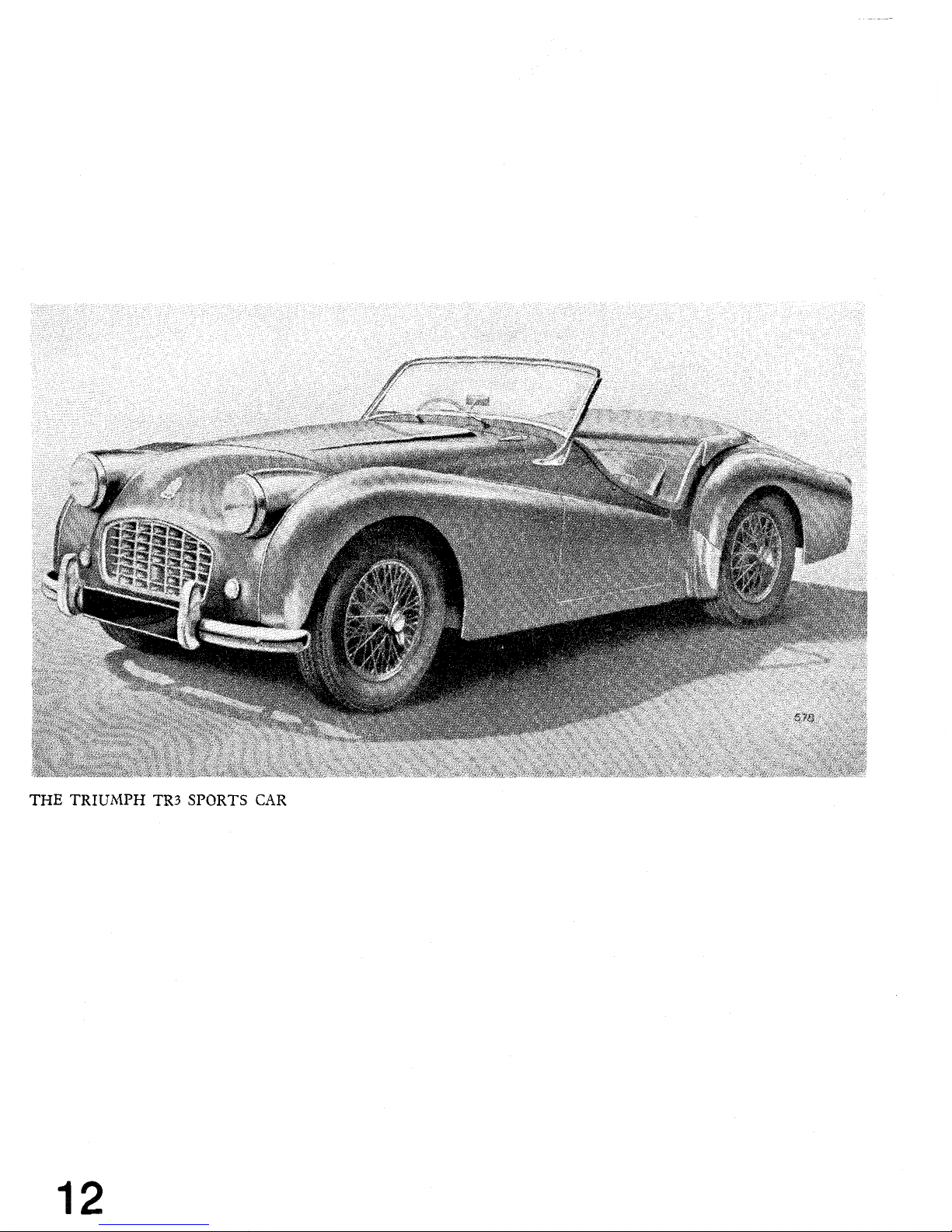
THE
TRIUMPH TR3 SPORTS
CAR
Page 13
FOREWORD
The vehicle has been designed so that a minimum of attention is required to
keep it in satisfactory running order. There are, however, certain maintenance
operations which must be undertaken regularly, and the object of this instruction
book is to assist even the non-technical owner to understand the various
operations required, and so ensure that the vehicle receives regular and correct
attention.
If in any doubt about the vehicle's performance the owner should at once
consult a Triumph dealer, preferably the one from whom the car was purchased.
Triumph dealers are very carefully selected and are suitably equipped to give
satisfactory and expert after sales service.
There is
a
Service School at the factory at which our dealers' representatives
acquire a first hand knowledge of up-to-date service procedure.
Valuable
information is given regarding special methods and equipment which greatly
assists in getting the various operations performed more expeditiously.
SPARE PARTS SERVICE
To ensure the best possible service on replacement parts it is important to
note the following points
:-
(a) The policy of the Triumph Motor Company is not to supply spare
parts direct to the general public, but
all supplies are directed
through
Distributors who, in turn, will supply their Dealers. The name and
address of the Distributors and Dealers can be obtained from the
Service and Spares Directory included with each motor vehicle.
(b) It is recommended that only
C6Stanparts
"
(i.e.,
genuine Standard/
Triumph spare parts)
are used, only these carry a guarantee.
Experience gained by the manufacturers ensures that only highest
quality material is used and the strictest accuracy maintained in
manufacture.
(c) If in doubt about a particular part required, it is always advisable to
give the vehicle commission number and engine number, in addition
to the fullest description possible.
THE STANDARD CAR REVIEW
is a journal published monthly which
gives authentic information regarding the activities and products of The
Standard
&
Triumph Motor Co. Ltd. It is obtainable from most Triumph
dealers. Please write to the Publicity Department
for a free specimen
COPY.
Owners of this model who wish to be kept informed of modifications and
competition tuning hints should register as
a
member of the Triumph Sports
Owners' Association
;
details are given in the booklet enclosed with this
literature, or apply to the Publicity Dept., Triumph Motor Co.
(1945)
Ltd.,
Canley, Coventry, for a copy of the book, together with
enrolment form.
The Company reserves the right, on the sale of any vehicle, to make before
delivery, without notice, alterations to or departures from the specification,
design or equipment, detailed, described or illustrated in this or other
Company publications.
3
SPORTS
CAR
Page 14
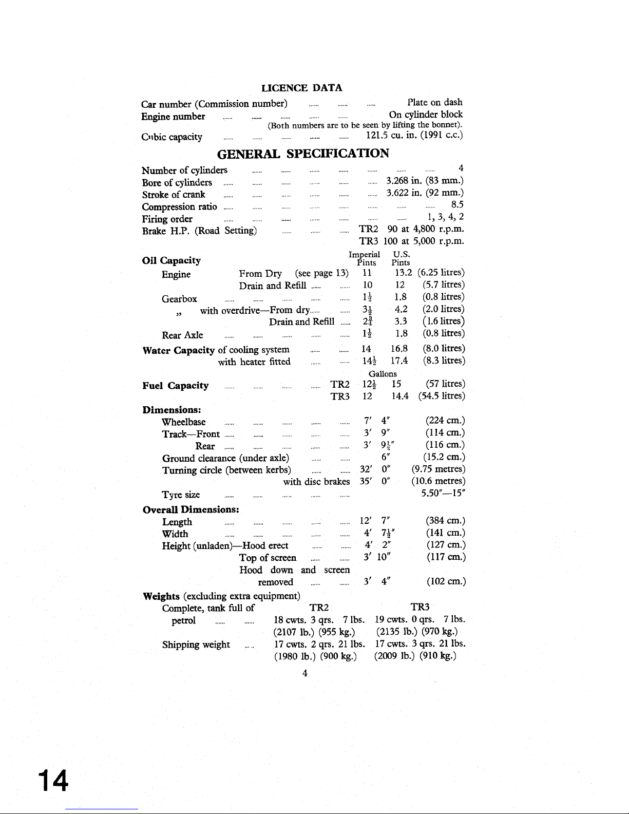
LICENCE
DATA
.....
......
Car number (Commission number)
......
Plate on dash
......
Engine number
........................
On cylinder block
(Both numbers are to be seen by lifting the bonnet).
..................
......
Cnbic capacity ...... 121.5 cu,
in.
(1991
CL.)
GENERAL SPECIFICATION
......
......
......
......
............
Number of cylinders
......
4
.....
......
......
Bore of cylinders ............
......
3.268 in. (83 mm.)
......
......
......
.....
......
Stroke of crank
......
3.622 in. (92 mm.)
......
......
......
......
......
......
......
Compression ratio
......
8.5
......
......
......
......
Firing order ..................
1,
3,
4,
2
......
......
Brake H.P. (Road Setting) ...... TR2 90 at 4,800 r.p.m.
TR3 100 at 5,000 r.p.m.
Imperial
U.S.
Oil Capacity
Pints Pints
Engine From
Dry
(see page 13) 11
13.2
(6.25 litres)
......
Drain and Refill ...,.. 10 12 (5.7 litres)
......
......
............
......
Gearbox
11 1.8 (0.8 litres)
,,
with overdrive-From dry ............ 34 4.2 (2.0 litres)
......
Drain and Refill 22 3.3 (1.6 litres)
......
......
......
......
Rear Axle
......
1i
1.8 (0.8 litres)
............
Water Capacity
of cooling system 14 16.8 (8.0 litres)
......
with heater fitted
......
14Q 17.4 (8.3litres)
Gallons
......
............
Fuel
Capacity
......
TR2 124 15 (57 litres)
TR3 12 14.4
(54.5 litres)
Dimensions:
......
......
......
......
Wheelbase
......
7' 4"
(224 cm.)
......
......
......
Track-Front ............ 3' 9" (1 14 cm.)
......
Rear
............
............
3' 9
$"
(116 cm.)
......
Ground clearance (under axle)
......
6" (15.2 cm.)
......
Turning circle (between kerbs)
......
32'
0"
(9.75 metres)
with disc brakes
35'
0"
(10.6 metres)
......
......
......
......
Tyre size
......
5.50"-15"
Overall Dimensions:
......
......
......
......
......
Length 12' 7" (384 cm.)
......
......
......
......
......
Width
4'
7;" (141 cm.)
......
Height (un1aden)-Hood erect ...... 4' 2" (127 cm.)
......
Top of screen
......
3'
10" (117 cm.)
Hood down and screen
removed
......
...... 3'
4"
(102 cm.)
Weights
(excluding extra equipment)
Complete, tank full of
TR2
TR3
......
petrol
......
18
cwts.
3
qrs. 7 lbs. 19 cwts. 0 qrs. 7 lbs.
(21071b.)(955kg.) (21351b.)(970kg.)
.....
Shipping weight
17
cwts. 2 qrs. 21 lbs.
17
cwts.
3 qrs. 21 lbs.
(1980 lb.) (900 kg.)
(2009 lb.) (910 kg.)
4
Page 15
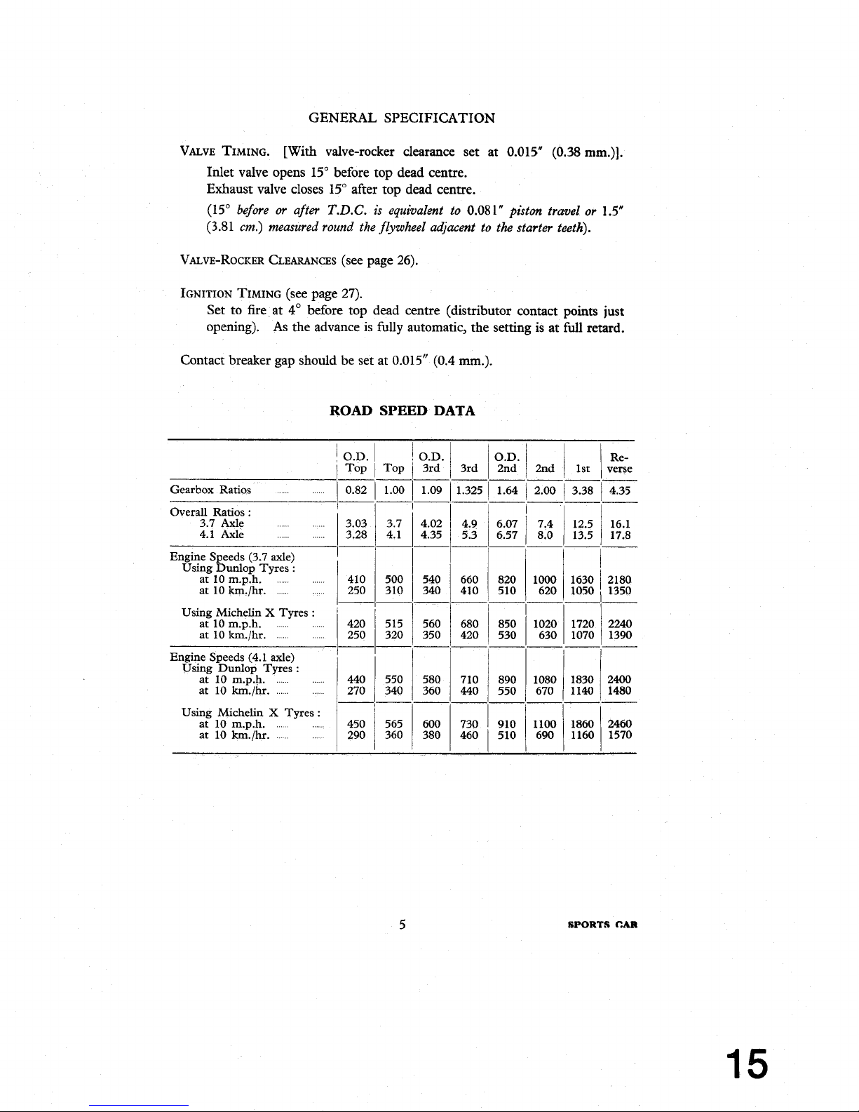
GENERAL SPECIFICATION
VALVE
TIMING.
[With
valve-rocker clearance set at 0.015" (0.38 mm.)].
Inlet valve opens 15" before top dead centre.
Exhaust valve closes 15" after top dead centre.
(15"
before or after
T.D.C.
is equivalent to
0.08
1"
piston travel or
1
S"
(3.81
cm.)
measured round the flywheel adjacent to the starter teeth).
VALVE-ROCKER CLEARANCES (see page 26).
IGNITION
TIMING
(see page 27).
Set to fire at
4' before top dead centre (distributor contact
points just
opening). As the advance is fully automatic, the semng is at
full
retard.
Contact breaker gap should be set at 0.015" (0.4
mm.).
ROAD
SPEED
DATA
1
O.D.
Gearbox Ratios
-
O.D.
3rd
1
.O9
Re-
verse
4.35
-
16.1
17.8
2180
1350
O.D.
3rd
/
2nd
1
2nd
--p
1.325 1 1.64 / 2.00
---
4.9
/
6.07
1
7.4
5.3
6.57 8.0
Overall Ratios
:
3.7 Axle
.
. .
. . . . . . . .
4.1
Axle
.
. . .
. . . . . . . .
l
-1-
l
Engine Speeds (3.7 axle)
Using
Dunlop Tyres
:
at 10 m.p.h.
at 10
!un./hr.
Using Michelin
X
Tyres
:
at 10 m.p.h.
at 10
km./hr.
Engine Speeds (4.1 axle)
Using
Dunlop Tyres
:
at 10 m.p.h.
at 10
km./hr.
Using Michelin
X
Tyres
:
at l0 m.p.h.
...
....,.
at 10 km./hr.
.....
....
SPORTS
CAR
Page 16
MANAGEMENT
OF
CAR
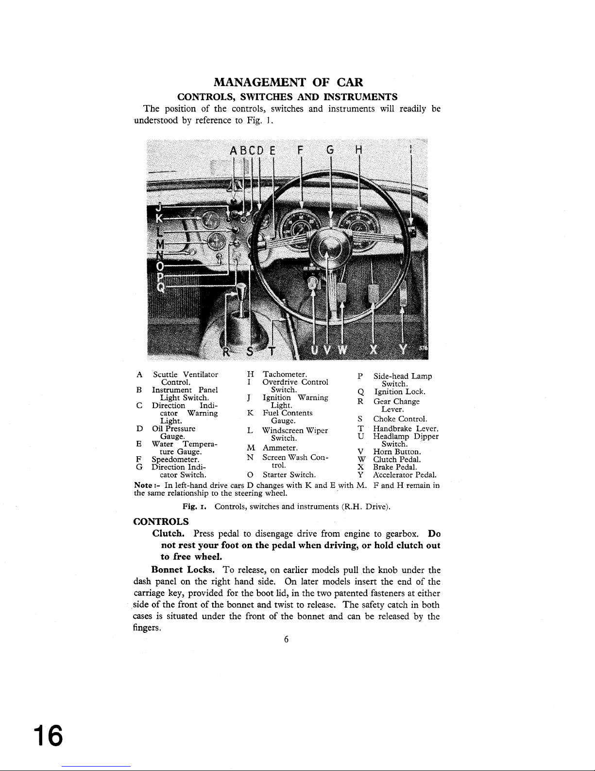
CONTROLS, SWITCHES AND INSTRUMENTS
The position of the controls, switches and instruments will readily be
understood by reference
to
Fig.
l.
Scuttle Ventilator
Control.
Instrument Panel
Light Switch.
Direction Indi-
cator Warning
Light.
Oil Pressure
Gauge.
Water Tempera-
ture Gauge.
Speedometer.
Direction Indi-
cator Switch.
Note
:-
the same relationship to the steering wheel.
In left-hand drive cars D changes with K and E with
Fig.
Controls, switches and instruments (R.H. Drive).
I.
Tachometer.
Overdrive Control
Switch.
Ignition Warning
Light.
Fuel Contents
Gauge.
windscreen Wiper
Switch.
Ammeter.
Wash Con-
Screen
trol.
Starter Switch.
Side-head Lamp
Switch.
Ignition Lock.
Gear Change
Lever.
Choke
Control.
Handbrake Lever.
Headlamp Dipper
Switch.
Horn Button.
Clutch Pedal.
Brake Pedal.
Accelerator Pedal.
M.
F and H remain in
CONTROLS
Clutch.
Press pedal to disengage drive from engine to gearbox.
Do
not rest your foot on the pedal when driving, or hold clutch out
to free wheel.
Bonnet Locks.
To relezse, on earlier models pull the knob under the
dash panel on the right hand side. On later models insert the end of the
carriage key, provided for the boot lid, in the two patented fasteners at either
side of the front of the bonnet and twist to release. The safety catch in both
cases is situated under the front of the bonnet and can be released by the
fingers.
6
Page 17
MANAGEMENT OF
CAR-Controls, Switches and Instruments
Choke Control.
See page 9 for full instructions.
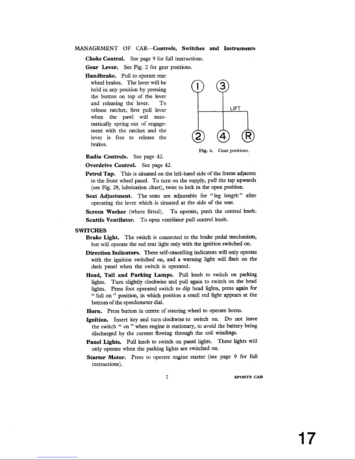
Gear Lever.
See Fig. 2 for gear positions.
Overdrive Control.
See page 42.
Handbrake.
Pull to operate rear
wheel brakes. The lever will be
held in any position
by pressing
Petrol Tap.
This is situated on the left-hand side of thc frame adjacent
to the front wheel panel. To turn on the supply, pull the tap upwards
(see Fig. 29, lubrication chart), twist to lock in the open position.
the button on top of the lever
and releasing the lever. To
release ratchet, first pull lever
when the pawl will
aulo-
matically spring out of engage-
Seat Adjustment.
The seats are adjustable for "leg length" after
operating the lever which is situated at the side of the seat.
LIFT
Screen Washer
(where fitted).
To operate, push the control knob.
Scuttle Ventilator.
To open ventilator pull control knob.
ment with the ratchet and the
lever is free to release the
brakes.
@ @
Fig.
2.
Gear
positions.
Radio Controls.
See page 42.
S
WITCHES
Brake Light.
The switch is connected to the brake pedal mechanism,
but will operate the red rear light only with the ignition switched on.
Direction Indicators.
These self-cancelling indicators will only operate
with the ignition switched on, and a warning light will flash on the
dash panel when the switch is operated.
Head, Tail and Parking Lamps.
Pull knob to switch on parking
lights.
Turn slightly clockwise and pull again to switch on the
head
lights. Press
foot operated switch to dip head lights, press again for
cc
full on " position, in which position a small red light appears at the
bottom of the speedometer dial.
Horn.
Press button in centre of steering wheel to operate horns.
Ignition.
Insert key and turn clockwise to switch on. Do not leave
the switch
cc
on " when engine is stationary, to avoid the battery being
discharged by the current flowing through the coil windings.
Panel Lights.
Pull knob to switch on panel lights. These lights will
only operate when the parking lights are switched on.
Starter Motor.
Press to operate engine starter (see page 9 for full
instructions).
7
SPORTS
CAR
Page 18
MANAGEMENT
OF CAR-Controls, Switches and Instruments
Windscreen Wiper.
Pull
to operate wipers ; they will only function
when the ignition is switched on. Push to stop when arms are in the
desired parking position.
Heater Switch. See page
42.
INSTRUMENTS
Ammeter. Indicates the flow of current into or out of the battery.
Fuel Gauge. Registers the amount of fuel in the tank.
It
operates
automatically when the ignition is switched on.
Oil
Pressure Gauge. Indicates pressure of oil being pumped to the
bearings.
The gauge should read
70
Ib./sq. in. (4.9 kg./sq. cm.) minimum
when the car is
travelling at normal speeds and the oil is hot. Only
a low pressure may be registered when the engine is idling or running
at low speeds
;
this is quite normal.
Speedometer. Registers vehicle's speed and total distance covered,
and is fitted with a trip which is cancelled by pushing up the serrated
knob (situated under the instrument) and turning anti-clockwise.
Tachometer. Indicates the speed of rotation of the engine in revo-
lutions per minute. (See page
10).
Ignition
Warning Light. Glows red when ignition is switched on
with the engine idling or stopped.
It is
an indication that current is
being drawn from the battery for the ignition circuit, or other purposes
that are controlled
by
the ignition switch.
Water Temperature Gauge. The gauge shows the temperature of
the cooling water at the thermostat. Under normal motoring conditions the water temperature should not exceed
185".
Page 19
MANAGEMENT
OF
CAR.
DRIVING
THE
CAR
TO
START THE ENGINE
IMPORTANT-When starting the engine at any time
:
If the engine does not start when the starter is operated,
do not re-
operate until both starter motor and engine have come to rest.
This is to avoid damage to the starter pinion.
Starting when Engine is Cold
Place the gear lever in the neutral position and see that the handbrake is
on. Pull the carburettor choke control out to the stop, switch on the
ignition and press the starter switch button. When the engine has become
sufficiently warmed up, turn the choke control and allow the control
to spring back to the
half-out
position and turn to lock in this position.
After one or two minutes driving, as the engine warms up, it will be
possible to permit the control to return home without causing the engine
to run with undue hesitation. If the battery has been allowed to get
into a run-down condition, it is better to use the starting handle. When
the engine fails to start, do not keep the choke control out too long or the
sparking plugs will become wet with petrol and it will be necessary to
remove and dry them. When the car has been left standing for some
considerable time, the fuel level in the carburettor float chambers may
have become rather low, due to evaporation. The hand primer on the fuel
pump can be used under such circumstances, before the starter is operated,
(see page
29).
When starting in very cold conditions, the clutch pedal may be depressed
when operating the starter to relieve the motor of the considerable drag
in the gearbox.
Starting with Engine Warm or Hot
When restarting the engine while it is
still
hot the accelerator pedal should
be depressed to about one-third of its travel before pressing the starter
button, the choke control should not be used.
Warming
up
In order to minimise cylinder wear the engine should be warmed up
quickly when starting from cold in winter
;
the engine may be " idled
"
for a minute to let the oil circulate, but it should not be allowed to idle for
long periods, neither should the engine be raced up to high speeds.
An engine speed of approx.
1,500
r.p.m. may be regarded as a desirable
warming up speed.
9
SPORTS
CAR
Page 20
DRIVING THE
CAR-The Engine
DRIVING
Gear Changing
For a smooth gear change into a synchronised gear (4th, 3rd & 2nd) the
movement should be slow and deliberate. The gear lever must always be
moved right home to secure full engagement. First and reverse gears are
not synchromesh, gear engagement being achieved by sliding the
respective gear into mesh. To avoid a noisy change do not engage
first gear with the car stationary and the engine revving at a speed greater
than 800
r.p.m., or when
travelling in access of
15
m.p.h.
Do not attempt to engage reverse gear whilst the car is travelling forward,
Desirable Speed Limits (Particularly in gears lower than top)
The engine is capable of" revving " very fast, yet the driver should avoid
continued
"
over-revving," which is most likely to occur in the lower gears.
We strongly recommend that in all gears the driver shall not drive
the car continuously at engine speeds above
4,500 r.p.m. How-
ever, during acceleration in the gears it is permissible to
attain
5,000 r.p.m. for short periods, which speed is indicated
by the red mark on the tachometer.
NEW ENGINES (see running adjustments)
During the early stages of a new vehicle's life, for at least the first 500 miles
(800
km.), the working surfaces of the engine will be bedding down. The
power and performance will improve only if during the running-in period
the vehicle is carefully driven at moderate speeds.
We recommend that the engine should be driven at speeds not exceeding 3,500
engine
r.p.m. during this period, and suggest that
"
running-in " should be
progressive. No harm is done if the engine is allowed to
"
rev " fairly fast
so long as it is thoroughly warm and provided it is not
pulling hard.
Do not
let the engine pull hard at low speeds, always select a lower gear.
Page 21
GENERAL UPKEEP
REGULAR INSPECTION
Every
250
miles
(400
km.)
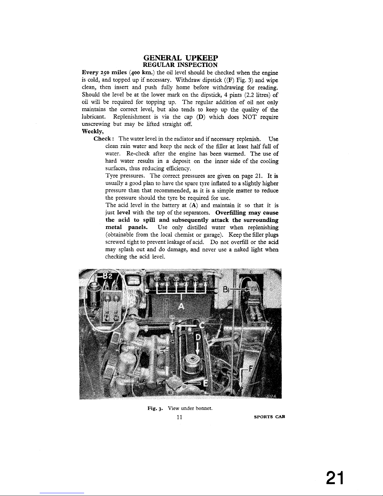
the oil level should be checked when the engine
is cold, and topped up if necessary. Withdraw dipstick
((F)
Fig.
3)
and wipe
clean, then insert and push fully home before withdrawing for reading.
Should the level be at the lower mark on the dipstick,
4
pints
(2.2
litres) of
oil
will
be required for topping up. The regular addition of oil not only
maintains the correct level, but also tends to keep up the quality of the
lubricant. Replenishment is via the cap
(D)
which does
NOT
require
unscrewing but may be lifted straight off.
Weekly,
Check
:
The water level in the radiator and if necessary replenish.
Use
clean rain water and keep the neck of the filler at least half full of
water.
Re-check after the engine has been warmed. The use of
hard water results in a deposit on the inner side of the cooling
surfaces, thus reducing efficiency.
Tyre pressures. The correct pressures are given on page
21.
It
is
usually a good plan to have the spare tyre inflated to a slightly higher
pressure than that recommended, as it is a simple matter to reduce
the pressure should the tyre be required for use.
The acid level in the battery at
(A)
and maintain
it
so that it is
just
level
with the top of the separators.
Overfilling may cause
the acid to spill and subsequently attack the surrounding
metal panels.
Use only distilled water when replenishing
(obtainable from the local chemist or garage).
Keep the filler plugs
screwed tight to prevent leakage of acid. Do not
overfill or the
acid
may splash out and do damage, and never use a naked light when
checking the acid level.
Fig.
3.
View
under
bonnet.
11
SPORTS
CAR
Page 22
GENERAL
UPKEEP-Cooling System and Lubrication
COOLING
SYSTEM
Filling
(see page 11).
Draining
For the purpose of draining, taps are provided in the bottom tank of the
radiator and at the rear of the cylinder block on the right-hand side. As
the cooling system is pressurised it will be necessary, when draining, to
remove the radiator
cap
(E),
Fig.
3.
If a heater is fitted, ensure that the cock is open before draining.
Anti-Freeze Mixtures
We recommend the use of Smith's " Bluecol," Duckham's Anti-freeze,
Esso Anti-freeze or Shell
"
Snowflake " Anti-freeze (inhibited Glycol
base compound) in order to protect the cooling system during frosty
weather and reduce corrosion to a minimum. The cooling system is
fitted with a thermostat and there is a risk of the radiator block freezing
while the engine is running during the warming up period when the
thermostat is shut, even though the car has been left in a warm garage
and water is not frozen at the start of the
run.
We recommend that you provide for the cooling system ample protection
against a sudden fall in temperature down to
0"
F.
(-18"
C.)
during
frosty weather by using
3
pints of anti-freeze.
In countries where sub-zero temperatures prevail, consult your Triumph
dealer regarding the quantity of anti-freeze required.
It is inadvisable to use anti-freeze for more than one season since
the inhibitor becomes exhausted and the components in contact
with the cooling water may corrode.
LUBRICATION
This
is
one of the most important subjects
in
connection with the upkeep of
a
car, and careful attention to the following instructions will be amply repaid by
the results obtained
For the recommended periods of lubrication, see the lubrication chart
folded inside the rear cover of this book.
The
correct lubricants to be
used are given on pages
51
and
52.
Page 23
GENERAL UPKEEP-Lubrication
Draining
To drain the engine, gearbox and rear axle, remove the plug provided
beneath each unit. This process is assisted by opening the filler to allow
ingress of air and by draining when the oil is hot,
i.e.,
immediately after
a run.
ENGINE
Only first quality oils are recommended for use in the engine sump. These are
each of the correct viscosity and character to
afford complete
lubrication
protection.
Additives which dilute the oil or otherwise impair this protection
must not be used.
After many thousands of
miles
running the rate of oil
consumption
will increase. When the rate becomes higher than 1 gallon per
1,000 miles
(1
litre per 400 km.), it will be desirable to use the next heavier
grade of the brand of oil you normally employ.
Engine
Oil
Drain Period
The frequency of the drain period should be related to the driving
conditions to which the vehicle is subjected. A period of
3,000
miles
(5,000 km.) is recommended as the interval for average driving conditions
as defined below.
It
should be reduced for unfavourable conditions
and may
be
extended for definitely favourable conditions.
Favourable
Long distance journeys,
with
little or no engine idling, on well surfaced
roads, reasonably free from dust.
Average
Medium length journeys on well surfaced roads with a small
proportion
of stop/start operation.
Unfavourable
Any of the following
:
(a)
Frequent stop/start driving.
(b)
Operation during cold weather, especially when appreciable
engine idling is involved.
(c)
Where much driving is done under dusty conditions.
We have found the use of an upper cylinder lubricant to be an advantage,
particularly in new engines, and recommend the use of such
a
lubricant,
particularly
until
the engine is thoroughly
cc
run-in." The lubricant should
be mixed with the fuel in the proportions given on the container. Such
lubricants
may
be used with advantage throughout the life of the vehicle,
particularly during wintry weather.
13
SPORTS
CAR
Page 24

GENERAL UPKEEP-Lubrication
Carburettors
Every 6,000 miles (10,000
km.)
unscrew the brass hexagon plug
in the top of each of the carburettors and top up with current
engine oil to the level of the
inner hollow shaft. Apply oil
also to the throttle linkages on
the engine, do not oil the bearings of the transverse rod attached to the scuttle as this will
seriously deteriorate the sealing
composition.
The
Oil Cleaner
The oil cleaner has been designed to filter the oil to a very
fine degree and the only attention it requires is to see that the
filtering cartridge
(B)
is removed and that a new replacement cartridge is fitted at periods
not exceeding 6,000 miles
(10,000
km.).
Later models
employ a
"
full-flow " cleaner,
and since a very
"fine"
filter
Fig.
4.
Oil
Cleaner
"
full-flow"
type.
cartridge is fitted it is important that this operation is carried out,
otherwise, as the filter becomes choked,
unfiltered oil will be passed to
the engine via the balance valve in
the cleaner. To renew the cartridge,
unscrew the securing
bolt and remove the container, the cartridge can
then be withdrawn. On some models it may be necessary to unclip and
swing the crankcase breather tube rearwards to provide sufficient room
for container removal.
Wipe out the container to remove foreign matter trapped by the filter,
using a non-fluffy cloth, and inspect afterwards to make certain that no
cloth fibres remain.
It may be desirable to discard the old container washer
(A),
replacing it
with a new one each time the cartridge is renewed. When re-assembling
the container, ensure that the washer is correctly positioned in the groove
in the filter body. Do not tighten the bolt
(C)
more than is necessary
to obtain an oil-tight joint.
Approximately one pint of oil will be lost due to the removal of the con-
tainer, and the sump should be topped up with new oil after assembly.
Page 25
GENERAL UPKEEP-Lubrication
The container should not be disturbed until cartridge renewal is required
;
as the accumulated dirt on the outside of the container may fall inside
and thus be carried into the bearings when the engine is re-started.
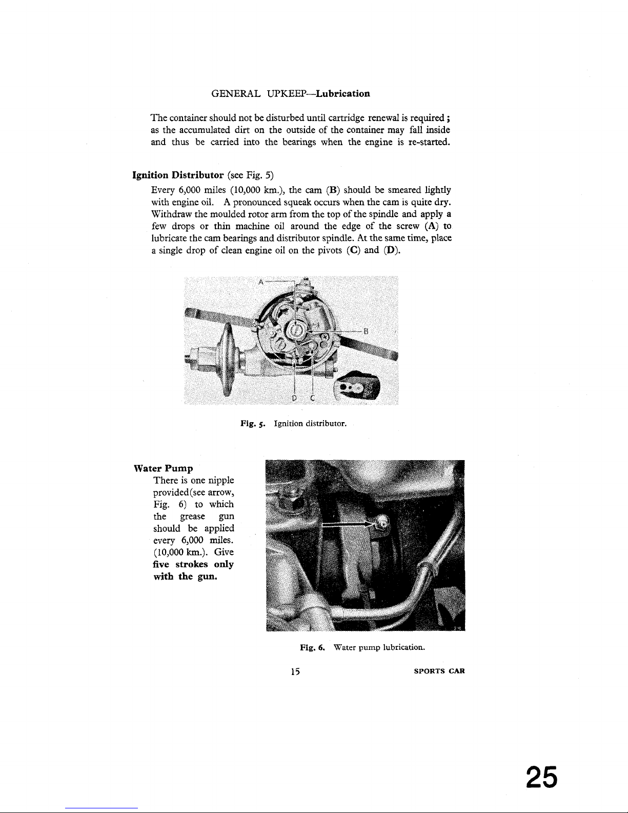
Ignition Distributor
(see Fig.
5)
Every 6,000 miles (10,000 km.), the cam
(B)
should be smeared lightly
with engine oil.
A
pronounced squeak occurs when the cam is quite dry.
Withdraw the moulded rotor arm from the top of the spindle and apply a
few drops or
thin
machine oil around the edge of the screw
(A)
to
lubricate the cam bearings and distributor spindle.
At
the same time, place
a single drop of clean engine oil on the pivots
(C)
and
(D).
Fig.
5.
Ignition distributor.
Water
Pump
There is one nipple
provided (see arrow,
Fig. 6) to which
the grease gun
should be applied
every 6,000 miles.
(10,000
km.).
Give
five strokes only
with
the
gun.
Fig.
6.
Water
pump
lubrication.
15
SPORTS
CAR
Page 26
GENERAL UPKEEP-Lubrication
Dynamo and Starter
The dynamo front bearing is packed with grease before leaving the works,
and after a considerable mileage the dynamo should be removed for cleaning, adjustment and repacking of the bearing with grease. This
should
be done preferably by the nearest Triumph or Lucas Service Depot. Every
12,000 miles (20,000 km.) pour a few drops of engine oil through the hole
in the centre of the rear end cap. The hole
is sealed from dust with a
small rubber plug.
The Starter is fitted with special bearings which require no lubrication.
Air
Cleaners. Every 6,000 miles (10,000 km.) it is advisable to remove the
air cleaners and wash in petrol, particularly the gauzes, after which soak
the gauzes in oil and allow to drain before finally wiping over
and refitting.
It
is very important to refit the air cleaners in the correct manner. Ensure
that the holes immediately above the setscrew holes in the carburettor
are lined up with the similarly positioned holes in the cleaner.
Oil
Filler Cap. Every 6,000 miles (10,000 km.) remove and swill the cap
in fuel, dry off and re-fit.
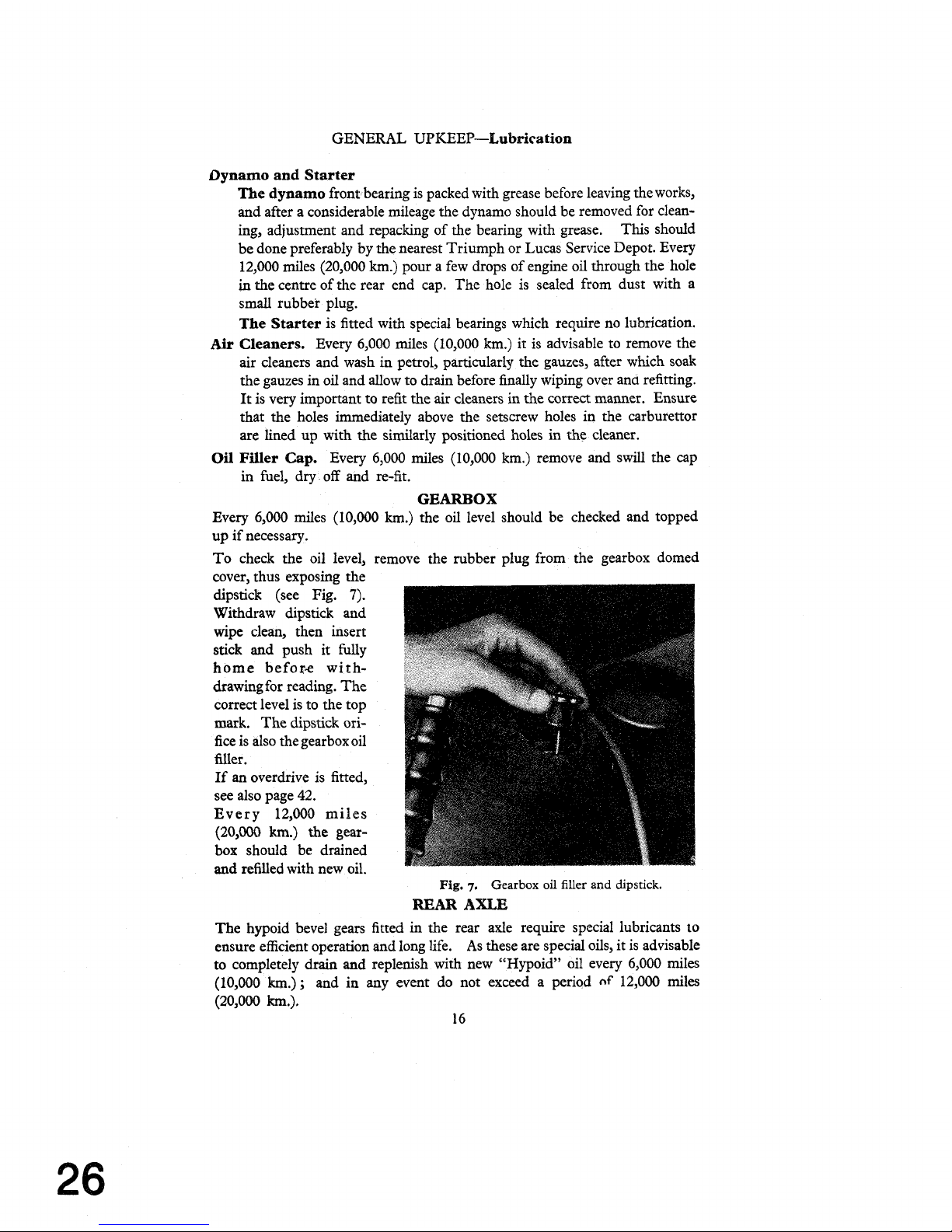
GEARBOX
Every 6,000 miles (10,000 km.) the oil level should be checked and topped
up if necessary.
To check the oil level, remove the rubber plug from the gearbox domed
cover, thus exposing the
dipstick (see Fig.
7).
Withdraw dipstick and
wipe clean, then insert
stick
and push it fully
home before withdrawing
for
reading. The
correct level is to the top
mark. The dipstick orifice is also the gearbox oil
filler.
If
an overdrive is fitted,
see also page 42.
Every 12,000 miles
(20,000
km.)
the gear-
box should be drained
and
refilled with new oil.
Fig.
7.
Gearbox oil filler and
dipstick.
REAR
AXLE
The hypoid bevel gears fitted in the rear axle require special lubricants to
ensure efficient operation and long life.
As these are special oils, it is advisable
to completely drain and replenish with new
"Hypoid" oil every 6,000
miles
(10,000
km.);
and in any event do not exceed a period
nf
12,000 miles
(20,000
km.).
16
Page 27
GENERAL UPKEEP-Lubrication
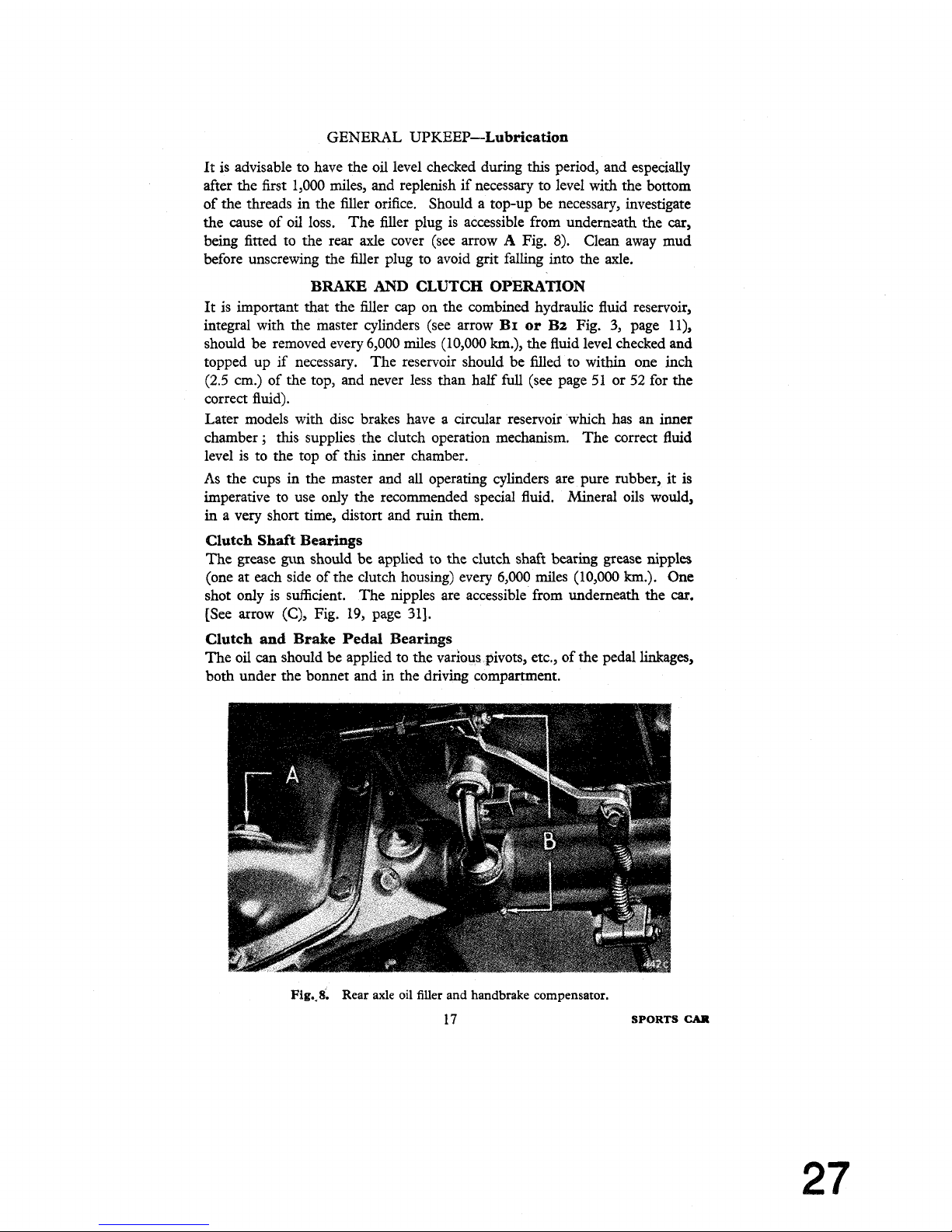
It is advisable to have the oil level checked during this period, and especially
after the first 1,000 miles, and replenish if necessary to level with the bottom
of the threads in the filler orifice. Should a top-up be necessary, investigate
the cause of
oil
loss. The filler plug is accessible from underneath the
car,
being fitted to the rear axle cover (see arrow A Fig.
8).
Clean away mud
before unscrewing the filler plug to avoid grit
falling
into the axle.
BRAKE
AND
CLUTCH OPERATION
It is important that the filler cap on the combined hydraulic fluid reservoir,
integral with the master cylinders (see arrow BI or B2 Fig.
3,
page ll),
should be removed every 6,000 miles (10,000
km.),
the fluid level checked and
topped up
if
necessary. The reservoir should be filled to within one inch
(2.5
cm.) of the top, and never less than half
full
(see page 51 or 52 for the
correct fluid).
Later models with disc brakes have a circular reservoir which has an inner
chamber
;
this supplies the clutch operation mechanism. The correct fluid
level is to the top of this
inner chamber.
As
the cups in the master and all operating cylinders are pure rubber, it is
imperative to use only the recommended special fluid. Mineral oils would,
in
a very short time, distort and ruin them.
Clutch Shaft Bearings
The grease
gun
should be applied to the clutch shaft bearing grease nipples
(one at each side of the clutch housing) every 6,000 miles (10,000
km.).
One
shot only is sufficient. The nipples are accessible from underneath the
car.
[See arrow
(C),
Fig.
19,
page
311.
Clutch
and
Brake Pedal Bearings
The oil
can
should be applied to the various pivots, etc., of the pedal linkages,
both under the
bowet and
in
the driving compartment.
Fig,$.
Rear
axle
oil filler and handbrake compensator.
17
SPORTS
CAR
Page 28
GENERAL
UPKEEP-Lubrication
Handbrake Cable Conduit
A
grease nipple is fitted in the conduit, as shown in the lubrication chart, to
which the grease gun should be applied every 6,000
miles (10,000 km.).
During the winter
months it is very important to keep the cable regularly
lubricated, as this prevents the entry of water which on cold nights will freeze,
thus locking the brake cable.
When lubricating the cable, grease is forced both ways and the gun should be
pumped until grease exudes at the end of the conduit.
Handbrake Compensator
Two grease nipples are provided on the compensator which is situated on
the rear axle casing (see arrow
B,
Fig.
8).
Front
ROAD
WHEEL HUBS
Recharging the hubs with grease on later models involves removing
the hubs, washing the bearings to remove all traces of the old grease
before liberally coating the rollers and races with new grease. This
should be carried out every 12,000 miles (20,000 km.). Where disc
brakes are fitted do not disturb the pipe unions but unbolt and move
the complete caliper, to
allow the hub and
disc to be removed, taking
care not to loose shims which may be fitted between the caliper and
the vertical link.
When replacing, ensure that the
inner race is tight against its shoulder.
Tighten the hub
nut until resistance is felt to hub rotation, then slacken
off
the nut by one flat of the hexagon and fit the split pin. This work
should
be preferably undertaken by your local Triumph agent who has
the necessary equipment for the task.
If
disc brakes are fitted
and the car is being used in competitions,
slacken off the hub nut one half flat and insert the split pin through one of
the two holes provided.
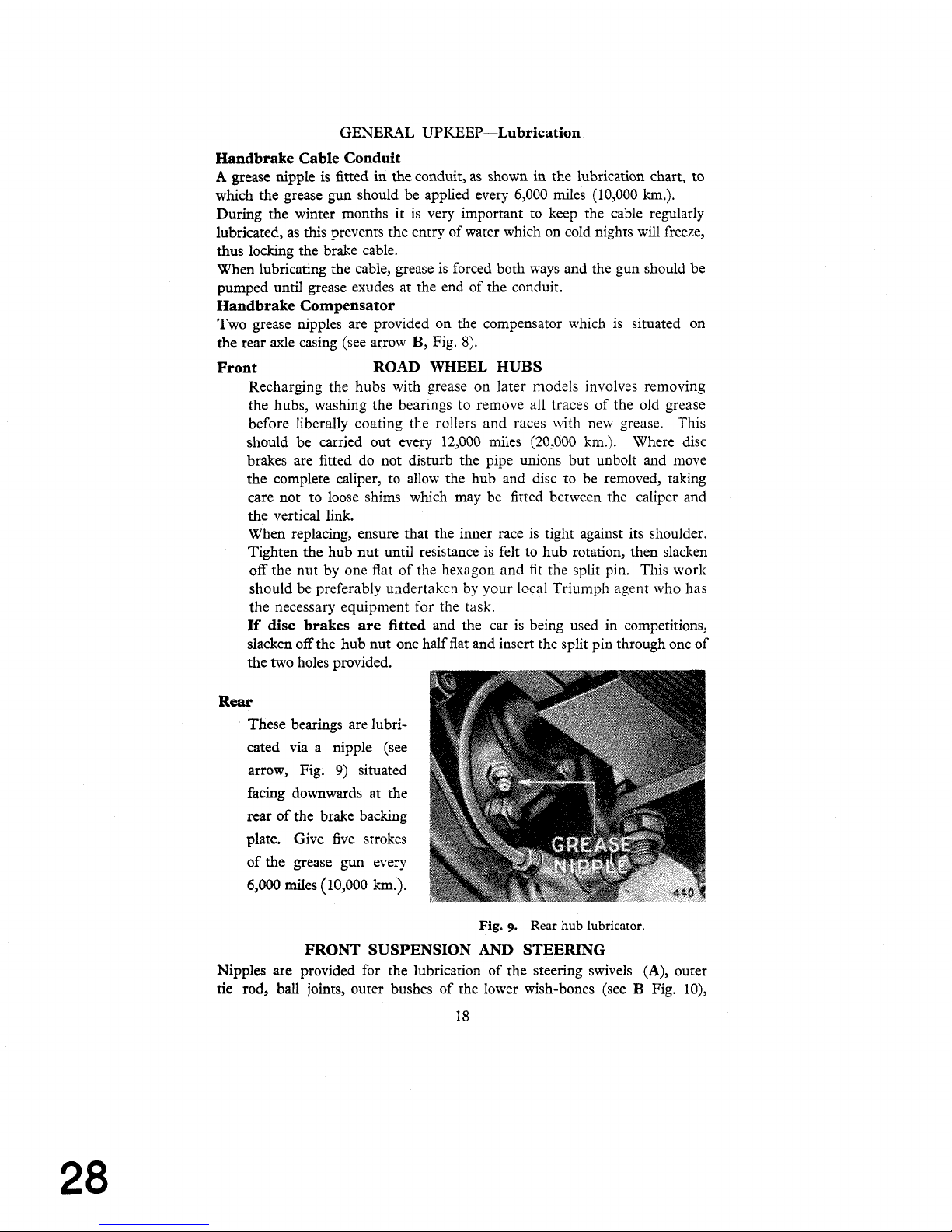
Rear
These bearings are lubricated via a nipple (see
arrow, Fig.
9)
situated
facing downwards at the
rear of the brake backing
plate. Give five strokes
of the grease
gun
every
6,000
miles
(10,000
km.).
Fig.
9.
Rear hub lubricator.
FRONT SUSPENSION
AND
STEERING
Nipples are provided for the lubrication of the steering swivels (A), outer
tie rod, ball joints, outer bushes of the lower wish-bones (see
B
Fig. 10),
Page 29
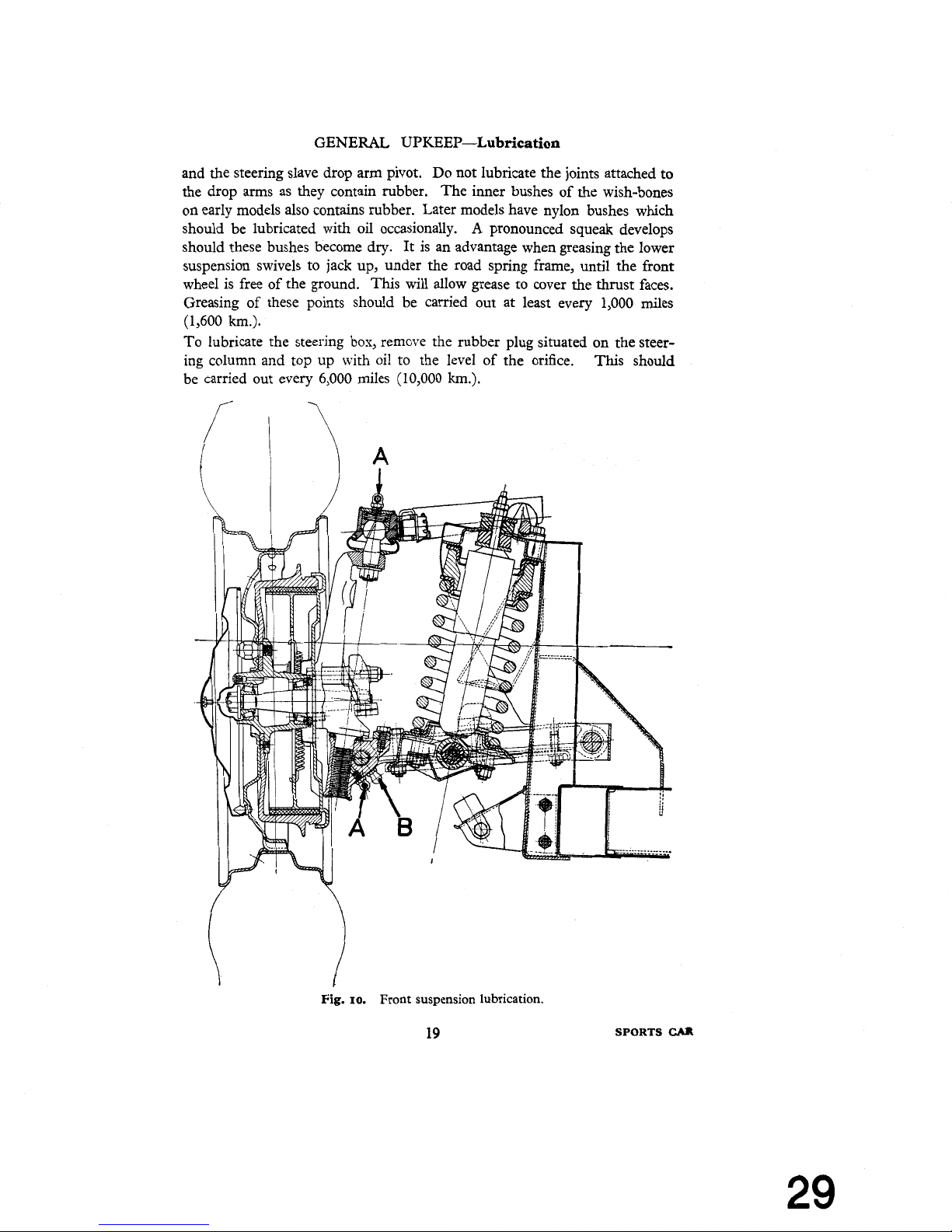
GENERAL UPKEEP-Lubrication
and the steering slave drop arm pivot. Do not lubricate the joints attached to
the drop arms as they contain rubber. The inner bushes of the wish-bones
on early models also contains rubber. Later models have nylon bushes which
should be lubricated with oil occasionally.
A
pronounced squeak develops
should these bushes become dry. It is an advantage when greasing the lower
suspension swivels to jack up, under the road spring frame, until the front
wheel is free of the ground. This will allow grease to cover the thrust faces.
Greasing of these points should be carried out at least every 1,000 miles
(1,600 km.).
To lubricate the steering box, remove the rubber plug situated on the steering column and top up with oil to the level of the orifice. This should
be carried out every 6,000 miles (10,000
km.).
Fig.
1
10.
Front suspension
lubrication.
SPORTS
CAR
Page 30
GENERAL UPKEEP-Lubrication
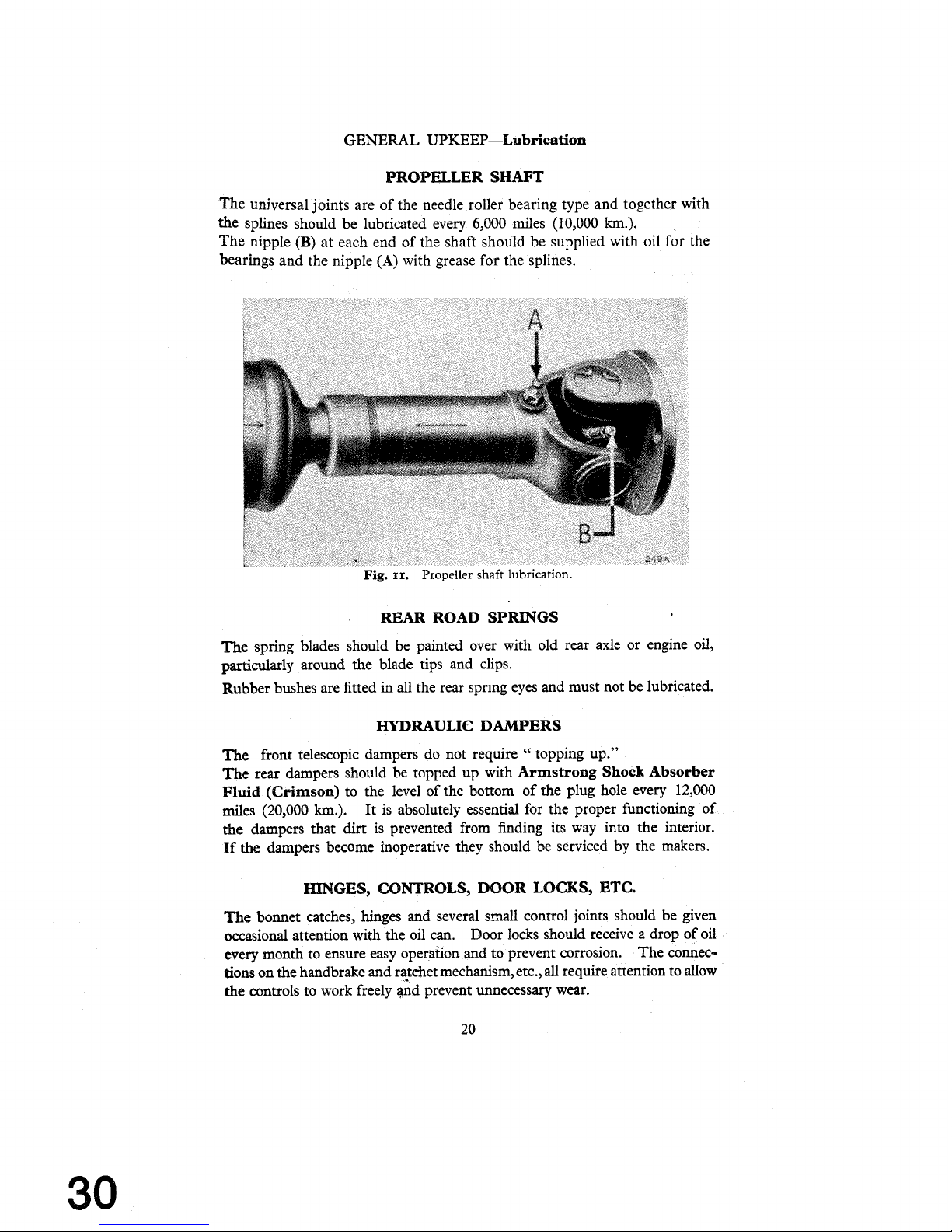
PROPELLER SHAFT
The universal joints are of the needle roller bearing type and together with
splines should be
the
The nipple
bearings and the nipple
(B)
at each end of the shaft should be supplied with oil for the
lubricated every 6,000 miles (10,000
(A)
with grease for the splines.
km.).
REAR
The spring blades should be painted over with old rear axle or engine oil,
particularly around the blade tips and clips.
Rubber bushes are fitted in all the rear spring eyes and must not be lubricated.
ROAD SPRINGS
HYDRAULIC DAMPERS
The
front telescopic dampers do not require " topping up."
The rear dampers should be topped up with
Fluid
(Crimson)
miles (20,000
the dampers that
If
the dampers become inoperative they should be serviced by the makers.
to the level of the bottom of the plug hole every
km.).
It is absolutely essential for the proper functioning of
dirt
is prevented from finding its way into the interior.
Armstrong Shock Absorber
12,000
HINGES, CONTROLS, DOOR LOCKS, ETC.
The bonnet catches, hinges and several S-all control joints should be given
occasional attention with the oil
every month to ensure easy operation and to prevent corrosion. The connections on the handbrake and
the controls to work freely
can.
Door locks should receive a drop of oil
r+&et mechanism, etc., all require
pd prevent unnecessary wear.
attention to allow
Page 31

GENERAL UPKEEP-Tyres
TYRES
The maintenance of correct tyre pressure is a large factor in tyre life and the
steering and suspension of the
car.
Examine the tyres occasionally for flints or other road matter which may
have become embedded
in
the tread. Clean off any oil which may have got
on the tyres by using fuel sparingly. Driving into or over sharp edged
kerbs is liable to fracture the walls of the tyres and should be avoided where
possible.
Tyre Pressures
Dunlop
:
Front
......
22
lb.'sq. in. (1.55 kg./sq. cm.).
Rear
.
.
24 lb./sq. in. (1.7 kg./sq. cm.).
These recommendations listed below apply to cars used under ordinary road
conditions either
inae
U.K.
or Overseas. Where cars are to be used for racing
or special high
spec$
testing where a sustained speed of more than 110 miles
per hour is anticipated, it is desirable that the
Dunlop Rubber Company
should
be consulted as to
the need for tyres of full racing construction.
I
OPERATING CONDITIONS
100/105 m.p.h.
elsewhere.
(a) Normal motoring in G.B. and under
similar road and traffic conditions
(b)
Continental type touring with lengthy
N.E.
periods at sustained speeds in excess
+
6
lb./sq.in.
of 85/90
m.p.h.
(0.42kg./sq.cm.:
(c) Motoring which is predominantly
and R.S.
regularly of the high speed Continental
touring type.
Over
100/105 m.p.h.
R.S.
R.S.
+
6
Ib./sq.
in.
:O.42 kg./sq.cm.)
R.S.
+
8 lb./sq.
in.
10.56
kg./sq.cm.)
Key:-
N.E.
Normal equipment,
i.e.
Dunlop or Dunlop Fort, as case may
be, at regular inflation pressures.
R.S.
Road Speed tyres at regular inflation pregures.
Michelin
X
Tyres : Front
.
24
1b.Isq.
in.
(1.7 kg./sq. cm.).
Rear
. .
28 1b.kq. in. (1.97 kg./sq. cm.).
These pressures should be increased by
3
@./sq. in. (0.35 kg./sq.
cm.).
if the car is driven consistently hard and fast.
2
1
SPORTS
CAR
Page 32

GENERAL UPKEEP-Tyres
Changing Position of Tyres
It is recommended that front tyres be interchanged with rear tyres at least
every 3,000 miles (5,000
km.).
Diagonal interchanging between left front and
right rear and between right front and left rear provides the most satisfactory
first change, because it reverses the direction of rotation and keeps the wear
of the tyres even and uniform.
FRONT
WHEEL
ALIGNMENT
The alignment of the front wheels is most important in its
eRect on tyre wear
and good steering.
Escessive toe-in will lead to severe tyre wear, particularly
on the
"
kerb side " front tyre.
Correct Wheel Alignment. The wheels should Toe-in
9".
When using Michelin X tyres set Parallel to Toe-in
#.
To Check and Adjust Wheel Alignment
If
adjusrment is found necessary it should be carried
out equally on the
two outer tie-rods. When adjustment is complete ensure that the ball
joints are in the centre of
"
swing " before securely tightening the tie-
rod locking nuts.
THE
JACK
A
screw jack is provided which
is adapted to lift either side of the
car as required.
To fit the jack
in
position shown,
turn
up the carpet and remove
the small cover plate situated
just in front of the seat.
Engage the lower lip of the boss
with the bottom edge of the
square hole, then swing the jack
into a vertical position and lift to
ensure correct engagement, making sure that it is right home in its
socket. Apply the handbrake or
chock the wheels which will
remain on the ground before
operating the
jah handle.
If a jack
is
used under the rear
axle case, take care to ensure
that the jack pad does not touch
the rear cover plate when
lifting,
Fig.
12.
Jacking
the
car.
otherwise there is a risk of damage and consequent oil leak.
Page 33

Dust may be removed from the exterior using a soft cloth only, but if it has
been wet at any time
it
is advisable to use a sponge and water. Always use
water when removing mud and when the car is clean finally wipe over with
an almost dry chamois leather. Washing alone will not keep up the brilliance
of the paintwork ofer an indefinite period and
it
may become necessary to
use a
cleaner to remove all
grease and dirt. It is advisable to acquire the
cleaner from a reputable dealer who will be able to advise you on the best
cleaner to suit the particular
paintwork of your car,
afterwards polishing
with some suitable preparation.
Special cleaners are available for removing traffic film and tar. Chromium
plated parts need cleaning with soap and water, and wax polishing is beneficial.
If,
due to neglect, the plate becomes spotted, it may be necessary to use a
chromium plate cleaner.
The interior of the car should be dusted occasionally and the carpets brushed
with a stiff brush. The upholstery may be cleaned by the application of a
little soap and damp cloth, followed by a final wipe down with an almost dry
sponge or wash leather. When a vacuum cleaner is available
it
can be used
with advantage to help
clem the interior.
DOOR ADJUSTME
The doors are provided
with
special locks which, when correctly adjusted,
prevent any movement of the closed door.
Only the str
repositioning
when
adjustment becomes necessary.
This adjustment should preferably
be
carried out by a coach fitter.
SOFT TOP STOWAGE
It is necessary to remove the soft top altoge~her when the car is required to
run in the open
condition. Take care not to fold the material too sharply.
The supports
may then be
hinged down flat behind the seats. When
refitting the soft top after erecting the supports always fasten it to
the body first and then pull
it
over the supports to fasten to the screen. When
fastened down the rubber backed roll of material attached to the top and
Nnning along the top edge of the
windscreen should be opened out and fitted
over the top lip of the windscreen frame to complete the sealing.
OPT TOP
FASTENERS
Two types of fasteners are used, " Lift the Dot " and " Tenax " (early
models only had
"
Tenax
").
When fitting either type& is only necessary
to push the fasteners over the securing stud as
showcin Fig.
13.
With
the
"
Tenax " type (as illustrated) do not press or pull the small knob before
engagement as there
will
be a risk of damage to the inner prongs. After
fitting, the knob may be pressed to ensure correct engagement.
To remove the fasteners, either
pull the small knob or in the case of the
"
Lift the Dot," do as its title suggests, lift the outer edge.
23
SPORTS
CAR
Page 34

BODYWORK
Fig.
13.
"Tenax" soft top fasteners.
It may be found advantageous when removing the fasteners from the screen,
to relieve the tension on the fasteners by applying a slight hand pressure, in
the forward direction, to the
corrier of the soft top where it passes over its
supports.
SPARE WHEEL
AND
TOOL STOWAGE
The spare wheel is housed in a compartment under the luggage locker. A key
is provided for the panel locks and to open, insert the key and give a half
turn
towards the centre of the car to release each catch. The tools are stowed as
shown
in
Fig.
14.
To place them
in
position the spare wheel should be
withdrawn about six inches
(15
cm.).
Fig.
14.
Tool stowage.
Page 35

RUNNING
Various adjustments are necessary from time to time in order to keep the
mechanism in efficient running order. The periods between depend largely
upon the manner in which the car is used and no definite time
for carrying out these corrections. The car should be examined however
every 6,000
can then be made (see page
miles (10,000
km.)
ADJUSTMENTS
can
be given here
and any adjustments which appear necessary
35).
ENGINE
Decarbonising and
It is recommended that the cylinder head be removed for decarbonising and
valve grinding after the first
attention to the valve seats, the metal of which becomes stabilised during
period. Thereafter it will be found that decarbonisation will be required
only after a period of about
gine is running satisfactorily after this period and that
normal compression, showing that the valves are seating reasonably well, it
much better to leave it alone.
The grinding of the valves becomes necessary in order not
the efficiency of the engine, but
and getting burnt.
We recommend that the work should be carried out by the skilled
at your nearest Triumph Dealer. For those who desire to do this work them-
selves, the main points to watch are
The procedure of turning the crankshaft in o
will
"
break " the seal of the cylinder head sh
this design of engine.
Once the cylinder head has been removed it is important that the
shaft is not rotated unless the cylinder sleeves are firmly clamped down
against their
washers fitted over the cylinder head studs marked
to overlap the adjoining cylinder liners, each being secured with a
cylinder head nut. If this precaution is not observed the sleeves may
rise, with consequent risk of water leaking into the crankcase after
assembly. On removal of the head and withdrawal of the push rods,
the passage ways in the
crankcase and sump must be sealed off with a clean sag or
The same applies to the rocker shaft
to prevent the entry of carbon particles which could do serious harm
the engine.
A
stick of soft solder is the most suitable tool for removing the carbon. On
no account should emery cloth or sandpaper be used.
It has been found advantageous to remove the tappets and clean the insides
just prior to refitting the cylinder head to
may
which
seatings.
Valve
seatings. This
have fallen into the chamber
Grinding
5,000
miles
(8,000
20,000 miles (32,000
to prevent a badly seating valve becoming worse
outlined below:
can
be accomplished by using two tubes and
block
leading to the camshaft and thence to the
oilway, both in the head
25
h.).
This is chiefly to give
this
km.).
Providing that the en-
each cylinder gives
is
only to increase
mechanics
crank-
4
and
5,
Fig.
15,
masking tape.
and the block,
to
ensure that any chips of carbon
are removed from the push-rod
a
Page 36

RUNNING ADJUSTMENTS-Engine
A
new gasket must be fitted each time the cylinder head is removed.
The plain side of the gasket must be downwards against the cylinder
block and should be coated on both sides
with
cc
WELLSEAL" or
similar non-setting sealing compound.
When replacing the cylinder head nuts, tighten them gradually in the
sequence shown in Fig.
15,
in
order to produce
an
even pressure on the
gasket and prevent undue strain in the cylinder head casting.
It
will
be necessary to
recheck
the nut tightness when cold to
loo-105
lb.
ft.
The valve springs are close-coiled at one end and should have the closecoiled end towards the cylinder head when refitting. Before tightening
down the rocker
pedestals, screw back each adjusting screw and ensure
that the ball ends of these screws engage correctly with the push-rods.
Failure to attend to these items may result in damage to the push-rods.
The
adary her valve springs must
be fitted to the exhaust valves.
Smother the rocker gear with oil, particularly where the rockers bear on
to
the valves before replacing the rocker cover. Ensure that the cork
washer is undamaged and
shellaced to the cover, otherwise oil may leak
through the joint.
After the first 1,000 miles (1,600
km.) the cylinder head nuts should be
checked for tightness, with engine hot, in the order shown in Fig.
15.
Fig.
15.
Order
of
tightening cylinder
head
nuts.
Valve-Rocker Clearances (measured cold)
On
earlier models the running clearances are .010" (0.25 mm.) inlet and
.012" (0.3
mm.) exhaust. Where aluminium rocker pedestals are fitted
(later models) the valve-rocker clearances should be set at 0.010"
(0.25
mm.) inlet and exhaust for both normal and high speed motoring.
Page 37

RUNNING
AD
JUSTMENTS-Engine
Adjustment
Remove the roeker cover and
turn
the engine crank with the aid of
the starting handle for half a revolution after the valve to be
adjusted has closed. It is easier to do this if the sparking plugs are
removed. This also provides an opportunity for inspecting
checking the sparking plug gaps.
Slacken the lock nut and adjust the rocker screw with a screwdriver
until the gauge is a sliding fit between the top of the valve stem and
the rocker face.
Now tighten the lock nut and check that the clearance has not
altered.
and
Ignition
Timing
On initial assembly the ignition is set as stated on page
Fig.
16.
Premium grade fuels of
Ignition
95
octane (research method) or higher must be
leads.
used for these engines, and with this fuel a
"
pink." However, with a substantial amount of carbon build up, it may
be necessary to retard the ignition slightly so that
just audible when pulling hard with the engine speed above
To advance ignition, rotate the knurled screw as indicated.
2"
on the distributor vernier scale represents
of the distributor,
5.
"
clean " engine will not
"
pinking " is only
1,500
Each division
the crankshaft.
The firing order is
1,
3,
4,
2.
To obtain T.D.C. position turn the crankshaft until the small hole in
the belt pulley is
Fourdegreesis equivalent to
in
line with the pointer attached to the timing cover.
&
(4.7
mm.) measured on the circumference
of the crankshaft fan pulley.
i.e.,
r.p.m.
4" on
Valve
Timing
5
See page
for correct valve timing.
27
SPORTS
CAR
Page 38

RUNNING
AD
JUSTMENTS-Engine
Sparking
Plugs
The sparking plugs were adopted for original equipment after lengthy
tests and as sparking plug types vary in suitability for different engines,
it is important that the correct type of plug be fitted when making
replacements, this is
:
Champion No. LlOS-$" reach.
In countries where the octane rating of the fuel is low, making it
necessary to use the lower compression ratio, it
Champion
L10
plugs.
For high speed touring however, use Champion No.
The gaps
(i.e.,
the width between the firing point of the centre electrode
and earth point) are originally set and should
(0.62
mm.).
Incorrect gap settings may cause misfiring or erratic slow
may
be desirable to use
L11S-y reach.
he
maintained at 0.025"
running. Faulty plug leads or cracked porcelain insulation in the sparking
plug
will also cause faulty
ignition, see also page
9.
Sparking plugs should be thoroughly cleaned, checked and adjusted (if
necessary) for gap setting after 6,000 miles (10,000 km.) use and at
12,000 miles (20,000 km.) should be replaced by new plugs.
Carburettors (Twin S.U.)
TR2
:
Type H4, Standard Needle
F.V.
For high speed and competition work use G.C. needles.
When
carburettors are fitted with oil bath air cleaners use
needles.
TR3
:
Type H6, correct needle for normal and competition work
When carburettors are fitted with oil bath air cleaners use CIW
needles.
AH
S.M.
Fig.
17.
Carburettors.
Page 39

Adjustment
As the needle size is determined during engine development, adjustment
of the carburettors is confined to correct idling adjustment. Remove the
air cleaners and
run
the engine
until
it has attained its normal running
temperature slacken one of the clamping bolts
(B)
on the throttle spindle
connection and disconnect the mixture control link
(G)
by removing one
of the fork swivel pins. Adjust the idling speed to approximately
500
r.p.m. by moving each throttle adjusting screw
(A)
&
(C)
an equal
amount. By listening to the hiss in the intakes, adjust the throttle adjusting
screws
until
the intensity of the hiss is similar on both intakes. This
will
synchronise the throttles. When this is satisfactory, the mixture should
be adjusted by screwing both the jet adjusting nuts
(E)
up or down to
exactly the same extent, at the same time keeping the jet levers
(F)
pressed forward to ensure that the jets are hard up against the nuts, until
even running is obtained. As these are adjusted, the engine will probably
m
faster, and it may therefore be necessary to unscrew the throttle
adjusting screws a little, each by the same amount,
in
order to reduce the
speed. When the mixture is correct on both carburettors, lifting the piston
of one of them with a penknife blade should make the engine beat become
irregular from excessive weakness. If lifting the piston about
3"
(3
mm.)
on one carburettor stops the engine and lifting the other about
Q'"
increases the engine speed, this indicates that the mixture on the
first
carburettor is set weak and the second is set rich. The first one should,
therefore, be enriched by unscrewing the jet adjusting nut one flat at
a
time and the second should be weakened off by screwing up the jet
adjusting nut in a similar manner. When the mixture is correct, the
exhaust beat should be regular and even.
If it is irregular, with the splashy type of misfire and a colourless exhaust,
the mixture is too weak. If there is a regular or
rythmical type of misfire in
the exhaust
beat, together with a blackish exhaust, then the mixture is too
rich. This should be noted when the air cleaners are again in position.
When reconnecting the mixture control link, make sure that the jet levers
are pressed
forward and the control rod
adjusted correctly for length so
that the clevis pins may be inserted freely while the jets are in this position.
The throttle spindle interconnection clamping bolts
(B)
should now be
tightened.
The desired fast idle necessary when the choke is in operation is controlled by adjusting screw
(D).
For further information on the tuning, adjustment and maintenance of
S.U. carburettors, you are advised to get in touch with the S.U.
Car-
burettor Co. Ltd., Wood Lane, Erdingron, Birmingham
24,
from whom
the necessary literature may be obtained.
Fuel
Pump
The mechanically operated fuel pump, mounted on the left-hand side of
the crankcase, provides a constant pressure of fuel
to
the carburettor.
A
hand primer is fitted, which can be used to pump fuel to the carburettors
29
SPORTS
CAR
Page 40

RUNNING
AD
JUSTMENTS-Engine
if
the float chamber is not already
full,
under which condition a slight
pumping resistance is felt before the lever reaches its stop. This resistance
ceases when the chamber is
full.
Fig.
18.
Fuel
pump.
The glass bowl acts as a sediment chamber for the petrol passing to the
pump. The foreign matter collects
on
the underside of the gauze and,
being washed off by petrol, sinks to the bottom of the bowl. To remove
the sediment, detach the bowl by unscrewing the
nut
at its base and wash
out the
bowl with the fuel that will be
in
it. When refitting the bowl,
tighten the nut just sufficient to ensure a fuel-tight joint, as over-tightening
may result in damage.
If
the pump
fails
to supply fuel to the carburett~rs
it
is advisable to attend
to the following points
:
(a) inspect the fuel pipe unions, which (if any are
loose) should be tightened up, (b) a blockage may have been caused
in
the fuel pipe, which may be removed by blowing through the pipe with
the aid
of
a tyre pump.
If,
after attending to the above points, the pump still fails to operate,
it
should be renewed and the old pump sent to the nearest
A.C.
or Triumph
Service Station.
Before doing any work on the carburettors or fuel pump which involves
disconnecting a fuel pipe it is important to turn off the fuel supply at the
tap on
the
chassis end of the flexible pipe. Failure
to
do this will allow the
petrol to drain away from the tank.
Page 41

RUNNING ADJUSTMENTS-Clutch
CLUTCH
A
Borg & Beck single dry plate hydraulically operated clutch is fitted and as
it is
correctly set before leaving the works,
it will be some considerable time
before it requires re-adjustment. The hydraulic master cylinder for the clutch
has a
conamon filler with the brake
Fig.
system. (See arrow
19.
Clutch
adjustment.
(B)
Fig.
3,
page
11.)
There is, however, a partition in the container to ensure that any possible
defect in one system does not affect the other.
Adjustment of the mechanism can normally only be judged as necessary at the
connecting rod between the operating cylinder and the shaft operating lever end,
see
Fig.19. The correct setting is when there is
.075"
(1.9 mm.) end float of
the
rod between operating cylinder and lever, in the " foot off" condition. To
achieve the correct setting, measure the total movement of the operating lever
by hand and
if
different from the specified amount release the locknut
(B,
Fig. 19) and adjus7the length of the connecting rod to the correct figure. The
adjustable connection between pedal and master cylinder is set on initial
bly and
If
MUST
a pipe has been disconnected, it will be necessary to bleed the system.
bleeder nipple
ing the system, see page
NOT
be tampered with as it wili never require adjustment.
is
shown by the arrow
34.
(A
fig. 19). For instruction on bleed-
assern-
A
BRAKES
The pedal operates the brakes on
all
four wheels hydraulically, whilst
the
handbrake control operates the brakes on the rear wheels by means of cables.
3
1
SPORTS
CAR
Page 42

RUNNING
AD
JUSTMENTS-Brakes
See page
17
for checking level of fluid
in
reservoir.
If it is found to be par-
ticularly low, it is an
indication that a leak has developed somewhere in the
system and it should be traced and rectified without delay.
It must be remembered that the presence of oil, grease or
sidar foreign
matter
on a drum brake shoe will seriously affect the coefficient of friction and in
Fig.
2oA.
Front
assembly.
Fig.
20B.
Rear
assembly.
Lockheed
Brakes.
consequence the retarding effect of that particular brake, in spite of the fact
that it is being applied with the same force as the others.
In such cases the
brake drum should be thoroughly cleaned with fuel and the brake shoes
replaced by new replacement shoes. Cleaning the
biake shoe is not satisfactory.
Do not re-line the shoes but fit either genuine
Lockheed or Girling replacement
shoes, depending
upon the installation. These shoes
have the right type of
lining machined to the
correct radii.
Should the shoes be removed,
care must be exercised to ensure that the pull-off
springs are located behind the shoes and hooked through the correct holes,
as
shown.
Adjustment of Brake Shoes
Lockheed Brakes (fitted on earlier models)
After a considerable mileage it may be found necessary to adjust the brakes.
Ths is evident
when the brake pedal has to be depressed to within
1"
of
the floor before the brakes operate. There are TWO adjusters to each
frmt wheel and
ONE
to each rear wheel as shown.
Page 43

RUNNING AD JUSTMENTS-Brakes
The following procedure should be followed to correctly adjust
the brakes:
1.
Apply the brakes hard, with the car stationary, to position the shoes
in
the drum, then release brake.
2.
Jack up the car, remove the nave plates and road wheels.
3.
Rotate hub until hole provided in the brake drum coincides with
screwdriver slot in
rnicram adiuster.
4.
Insert a screwdriver and turn the adjuster clockwise
until
the shoe
contacts the brake drum, then
turn
adjuster back one notch. There
is a constant drag on the rear wheels due to the action of the differ-
ential and the axle oil.
Do not confuse this with the brake drag.
5.
Replace wheels and nave plates, then remove jack.
Girling
Brakes (fitted on later models)
The disc brakes, fitted to the front axles, are self-adjusting and should
only need replacing when the shoe pads are reduced to approximately
4"
(3
mm.)
thickness.
Fig.
21A
Front
Assembly.
Fig.
ZIB
Rear Assembly.
Girling Brakes.
The rear brakes are provided with a small adjuster which is positioned
on the backing plate, above the axle case, and easily accessible with the
road wheel removed. To correctly adjust the shoes,
turn
the adjuster
clockwise
until
the shoes are hard against the drum, then slacken off
adjuster by one notch. The general precautionary remarks as mentioned
for the
Lockheed brakes applies
equally to the Girling assemblies.
33
SPORTS
CAR
Page 44

RUNNING
ADJUSTMENTS
Handbrake Adjustment (both makes)
Adjustment of the rear brake shoes as previously described automatically
readjusts the handbrake mechanism. The cables are correctly set before
leaving the works, and only maladjustment will result from tampering with
the mechanism.
Bleeding the Brake and Clutch Hydraulic System
If a pipe joint is uncoupled, the wheel cylinder cups or clutch operating cyl-
inder are inspected or replaced, the system must be bled in order to expel any
air which may have been admitted.
Air is
comprcssible, and its presence
in
the system will affect the working
of the brakes and clutch.
Whilst the majority or owners will prefer to have these operations carried
out by a Triumph Agent, for the benefit of those desiring to carry out
their own running adjustments, the procedure is as follows
:
1.
Wipe clean the bleeder nipple and fit a piece of rubber tube over ir,
allowing the tube to
hang in a clean container partially filled with
fluid,
so that the end of the pipe is below the level of the fluid.
2.
Unscrew the bleeder nipple one complete turn with a suitable spanner.
There is only one bleeder nipple to each wheel and one nipple on the
clutch operating cylinder.
3.
The fluid reservoir should be filled before commencing the bleeding
operation, and must be kept at least half-filled during the whole
operation, otherwise more air will be drawn into the system via the
master cylinder. Always clean the area around the plug before
removing it; this will lessen the risk of
grit falling into the chamber
after removal of the plug.
4.
Depress the pedal quickly and allow it to return without assistance.
Repeat this pumping operation with a slight pause between each
depression of the pedal. Observe the flow of fluid being discharged
into the glass jar and when all air bubbles cease to appear, hold the
pedal firmly down and securely tighten the bleeder nipple.
NOTE.-Depending upon the position at which a pipe joint in the brake
system has been uncoupled, it will be necessary to bleed the system at
either both front or both rear wheels. If the pipe was uncoupled at the
master
cylinder, then the system must be bled at all four wheels.
PROPELLER
S
If the propeller shaft has been taken apart for any resaon
it
is essential when
re-assembling the front end
splines to see that the arrows on the universal joint
and
propeller shaft end are in line (see Fig.
11,
page 20), so that the propeller
shaft
will
transmit uniform motion.
Page 45

RUNNING ADJUSTMENTS
The front telescopic dampers fitted do not require any adjustment or topping
up. If the dampers are removed, or for some reason new ones are fitted, it is
advisable to hold them the right way up (in the case of the rear dampers
check the level of the fluid and replenish if necessary), then pump the pistons
to
each end of the stroke. This pumping action dispels any air which may
have entered the chambers. After this operation check the fluid level in the
rear dampers, and in both cases keep the dampers the right way up until
they are fitted into place.
LOOSE
BOLTS
AND
NUTS
All the vital nuts are locked in position by split pins, locking wire, or by an
additional lock nut or lock washer.
It
is, however, desirabIe that the car should
be examined
every
6,000
miles
(10,000
km.) so that if any nut is found to be
loose it may be tightened. The wheel nuts can periodically be checked by
the owner himself and occasionally removed,
oiled and refitted.
The general
examination of the chassis is a mechanic's job.
SPORTS
CAR
Page 46

ELECTRICAL
SYSTEM
A
12
volt earth return (or one wire) lighting and starting set is fitted.
One
cable should be disconnected from the battery terminal before
removing any electrical unit, otherwise there is a risk of a serious
"
short."
A
list of the maker's numbers and descriptions of all electrical equipment
will be found on page 41.
IGNITION
Failure of the red warning light will not affect the ignition system, but the
bulb should be replaced at the earliest opportunity. The high tension leads
should be examined occasionally and if they are perished or worn through,
replace with the correct ignition cable, which should be obtained only from
your dealer, and should be of the correct length.
The moulded distributor cover should be removed occasionally and wiped all
over with a soft cloth. See that the carbon brush on
the
inside of the moulding
works freely in its holder. Clean away any trace of dirt or dust around the
contact breaker points. The points should be adjusted to give a maximum
gap of 0.015" (0.5 mm.). The distributor fitted to this vehicle has the radio
suppressor built into
the distributor head. This, of course,
means that an
outward inspection of the ignition and coil leads a suppressor will not be
apparent.
If a replacement or spare distributor head is required,
take care to ensure that it is of the correct type with the long carbon
pick-up, which is,
in
fact, the suppressor.
THE
BATTERY
Keep the terminals clean and well covered with petroleum jelly. If they are
corroded, scrape them clean, assemble and cover with petroleum jelly. Wipe
away all
dirt
and moisture from the top of the battery, and make sure that
the connections are clean. Do not over-tighten the wing nuts securing the
battery as this may result in the case becoming cracked.
THE
DYNAMO
The dynamo is of the compensated voltage type
and
operates in conjunction with
the
regulator unit which is housed alongside the cut-out in the control box.
The regulator unit ensures that the dynamo charges the battery
at
the rate
best suited to its condition. It automatically provides a large charging
Page 47

ELECTRICAL SYSTEM-Dynamo,
Control Box and Fuses
current for a discharged battery and a low trickle charge for a battery in
the fully charged state. The cut-out, operated by dynamo voltage, prevents
discharge of the battery through the dynamo when the dynamo is not
charging, in which condition the ignition warning light will be glowing.
Belt Tightness
It is important that the belt is sufficiently tight to drive the dynamo
but not too tight as would put undue load on the dynamo and water pump
bearings. The correct tension is achieved when the belt can be pressed
inwards
&"--;"
(13-19
mm.) on the longest run,
i.e.,
from the dynamo
pulley to the crank pulley.
It is essential after adjustment has been
made to securely tighten the fixing bolts.
THE STARTER MOTOR
Cleaning and Lubrication
The starter brush gear and commutator will not normally require attention.
After 48,000 miles (80,000
km.)
however, it is advisable to have the
unit
serviced at a Triumph or Lucas Service Depot.
Should the starter pinion become jammed
in
mesh with the flywheel,
then it
can
be released by turning the crankshaft with the starting handle
in
the normal manner, or select top gear and rock the car backwards and
forwards until the pinion releases itself. Do not forget to switch off
the
ignition when carrying out this operation.
CONTROL BOX
The control box, mounted on the scuttle, houses the voltage regulator and cutout. These units are carefully and accurately set before leaving the works and
must not be tampered with.
FUSES
The fuse carrier is located forward of the control box and houses two operating
and two spare fuses. The top fuse
(50
amp.) protects the horn, while the other
fuse
(35
amp.) protects those items which
can
only operate when the ignition
is switched on,
i.e.,
direction indicators, windscreen wipers, brake light,
petrol gauge and heater
(if fitted).
When replacing a fuse, it is important to use the correct replacement; the fusing value is marked on a
coloured paper slip inside the tube.
A
blown fuse will be indicated by the failure of all the units protected by it
and is confirmed by examination of the fuse. If it is not possible to locate
the
cause of the trouble and the new fuse blows immediately, the equipment
should
be
examined
by
a Triumph or Lucas Agent or Service Depot.
37
SPORTS
CAR
Page 48

ELECTRICAL
SYSTEM-Dynamo, Control Box and Fuses
current for a discharged battery and a low trickle charge for a battery in
the fully charged state. The cut-out, operated by dynamo voltage, prevents
discharge of the battery through the dynamo when the dynamo is not
charging, in which condition the ignition warning light will be glowing.
Belt Tightness
It is important that the belt is sufficiently tight to drive the dynamo
but not too
tighc as would put undue load on the dynamo and water pump
bearings. The correct
tension is achieved when the belt can be pressed
inwards
&"--2"
(15-19
mm.) on the longest run,
i.e.,
from the dynamo
pulley to the crank pulley,
It is essential after adjustment has been
made to securely tighten the fixing bolts.
THE
STARTER MOTOR
Cleaning and Lubrication
The starter brush gear and commutator will not normally require attention.
After 48,000 miles (80,000
km.)
however, it is advisable to have the unit
serviced at a Triumph or
Lucas Service Depot.
Should the starter pinion become jammed
in
mesh with the flywheel,
then it
can
be released by turning the crankshaft with the starting handle
in
the normal manner, or select top gear and rock the car backwards
and
forwards until the pinion releases itself. Do not forget to switch off the
ignition when carrying out this operation.
CONTROL BOX
The control box, mounted on the scuttle, houses the voltage regulator and cutout. These units are carefully and accurately set before leaving the works and
must not be tampered with.
FUSES
The fuse carrier is located forward of the control box and houses two operating
and two spare fuses. The top fuse
(50
amp.) protects the horn, while the other
fuse
(35 amp.) protects those items which can only operate when the ignition
is switched on,
i.e.,
direction indicators, windscreen wipers, brake light,
petrol gauge and heater
(if fitted).
When replacing a fuse, it is im-
portant to use the correct replacement; the fusing value is marked on a
coloured paper slip inside the tube.
A blown fuse will be indicated by the failure of all the units protected by it
and is confirmed by
examination of the fuse. If it is not possible to
locate the
cause of the trouble and the new fuse blows immediately, the equipment
should
be
examined by a Triumph or Lucas Agent or Service Depot.
37
SPORTS
CAR
Page 49

ELECTRICAL
To
CHECK
AND
ADJUST
ALIGNMENT
Park the car in front of a garage door or
SYSTEM-Lamp
wall
and square to
must stand on level ground and the front of the lamps should be
irnztely
25
ft.
(7.5
m.) from the " screen." The car should
the tyres at the correct pressures.
A
paint
should
bomet,
above the ground level as indicated
(A),
measured equally about the centre
oil
ehc
head lamps and adjust the lamps,
of each
circle of light coificides
be marked on the screen in fine
Two
crosses should
be
drawn
with
by
on
(B),
the
the
and
point
if
necessary,
cenxre
with
"
xsrcn
35i"
(see
of
Fig.
its
it.
The car
approx-
be
unladen and
the centre
"
27"
(1,150 mm.)
231,
until
of
(680
warn.)
apart
Switch
the centre
respective cross.
he
Page 50

ELECTRICAL SY
STEM-Lamps, etc.
If adjustment is necessary, proceed as follows
:
Withdraw the front rim after removing the securing screw.
Remove
the dust-excluding rubber. This will reveal three screws (see arrows,
Fig.
24),
which can be adjusted to align the reflector correctly. When
the correct alignment has been obtained, replace the rubber and rim.
It is advisable to start adjustment with each screw screwed out half-way
;
this will ensure correct fitting of the rim when assembled.
Parking Lamps (Front) and Direction Indicator Flashing Lamps
To remove bulb, peel back the rubber ring and remove rim, then the bulb
can be withdrawn. When replacing rim, first slip the edge over the two
small lugs, then peel back rubber as rim is fitted. Ensure that the rubber
is located correctly over the rim edge, otherwise vibration may cause the
rim to become detached.
Tail and Direction Indicator Flashing Lamps
To gain access to the bulb, remove the cover, which is secured by two
screws.
Number Plate Illuminator and Brake Lamp
To gain access to the bulbs, remove the securing screw and withdraw
the cover.
Ignition Warning Light
Each bulb holder can easily be
Direction Indicator Warning Light
withdrawn from the rear of the
High Beam Warning Light
panel for bulb renewal.
Instrument Panel Lights
Replacing these bulbs is best left to the safe hands of a Service Station.
WINDSCREEN WIPER
For operation, see page
8.
DIRECTION INDICATORS
These are of
the
flashing type operating in the dual filament bulbs
in
the
parking lamps at the front and the tail lights at the rear. The flasher
unit
is
situated close to the control box underneath the
bonnet.
WINDTONE HORNS
Each electric horn, before being passed out of the works, is adjusted to give
its best performance and
will
give long periods of service without any attention.
No adjustment is required in service.
If for any reason the note is unsatisfactory, do not attempt to dismantle the
horn, but return it to a Lucas Service Depot for examination.
Page 51

ELECTRICAL SYSTEM-Spedication
ELECTRICAL COMPONENT SPECIFICATION
1
Model Service ~ucas 1 volt-
l
Battery
Control Box
Coil
Dynamo
Distributor
Starter
Fuse Box
Flasher Unit
Horns
Windscreen
Wiper Motor
petrol Gauge Jaeger
Tank Unit
GTW9A/2 4011557 Head Lamps
......
1
RB106/2
......
B12 type L (home model)
......
C39PvL,21
type
DM2 type
1
V167 or 40480A
......
~418~ 25541F Front Parking Lamps
type V164 Tail Lamps
......
S.F.6
F.L.3
......
l
I
DR2 (-73105 Indicator Warning Lights
......
'
TA l&
I
No. No. age Watt.
---
1
37182 Left-hand dip, both lamps
Left-hand dip, both
L0
1
40403A
l
033240 Number Plate Illumina-
35003A
(export model)
Fght-hand
Vertical dip
tion and Brake Lamp
Lights and Direction l 987 12 2.2
~0.i
Fuses
~
......
di~
.. . . . .
1
>,
l
'
I
....
. .
50 amp. l 188219
I
35 amv. I 188218
I
Servrce
I
No
SPORTS
CAR
Page 52

RADIO
For operating instructions, see the radio leaflet provided with the set. The
set is protected against possible electrical damage due to a short by a
5
amp.
fuse housed in the main lead union. The aerial mast should always be
lowered when the set is not operating.
HEATER
The heater is of the re-circulating type, with a combined rheostat and
ON/OFF switch on the dash panel to regulate the speed of the fan. At
the right-hand rear end of the cylinder
head, under the bonnet, a screwed
cock can be turned to vary the amount of hot water which is to be fed
to the heater unit from nil to maximum flow. Shutters on the underside
of the heater unit control the downward flow of air from the heater into
the car. Closing the shutters will not
affect the air flow to the demister slots.
Operation
The Laycock de Normanville overdrive unit effects a reduction in overall
gear ratio by means of a train of epicyclic gears which are brought
into action by a hydraulically operated cone clutch. Movement of the
electrical switch mounted on the outside of the dash panel will bring the
overdrive into operation. To
tzke the overdrive out of operation, return
the switch to its original position. The electrical circuit is
only complete
when the gear
lever is in
the position of top gear on earlier models and top,
3rd or 2nd gears on later models. Care should be taken on the earlier models
not to move the gear lever out of the position of top gear at road speeds
in
excess of
75
m.p.h.
(120
k.p.h.), and
it
should be remembered also that if
the overdrive switch
is
made, returning the gear lever from third to top
gear will automatically re-engage the overdrive unit.
Lubrication
The oil used for both lubrication and for the hydraulic pump
is
the same
as and connected with that of the gearbox. The two units also having a
common filler orifice in the gearbox top cover. With an overdrive fitted it
is inadvisable to use
hypoid gear oils as these may be detrimental to
the
operation of the unit.
Draining
There
is
a drain plug fitted to the overdrive unit, and when draining the
gearbox it is necessary to remove both the drain plug on the gearbox and
the drain plug on the overdrive unit.
WIRE
WHEELS
Cars fitted with disc brakes have detachable hub extensions each secured by
four nuts. This should be checked occasionally for tightness and especially
after the first
500
miles from new or when replacement parts are fitted.
The correct tightness is
60-65
ft. lb.
Page 53

Fig.
25
Engine cross section.
43
SPORTS
CAR
Page 54

Page 55

SPORTS
CAR
Page 56

Page 57

710 9N19N3
80
37XV XVXX
(170
HLIA LNI
Page 58

RECOMMENDED LUBRICANTS-BRITISH ISLES
MOBIL
Mobiloil
A
WAKEFIELD
I
B.P.
Esso
ENGINE
Summer
3uckham's NOL
"
Thirty
Castrol Energol
XL
I
S.A.E. 30
Shell X-100
30 Esso Extra
Motor Oil
2owi30
Winter
Duckham's
NPL
"
Twenty
Mobiloil
Arctic
Mobil
Upperlube
Castrolite
I
Energol
S.A.E.20W
Shell X-100
20/20w
Esso
U.C.L.
Upper Cylinder
Lubricant
......
Duckham's
Adcoids
Castrollo Energol Shell
Donax U
GEARBOX
3uckham7s NOL
"
Thirty
Mobiloil
A
Castrol Energol
XL
I
S.A.E. 30
Shell X-100
30
Essolube
30
REAR AXLE
STEERING GEARBOX
:
PROPELLER
SHAFT JOINTS
. ..
Duckham's
Hypoid 90
Mobilube
G.X. 90
Castrol
I
Energol
HYPY
EP
S.A.E. 90
Esso Expee
Compound 90
Shell Spirax
90 E.P.
Duckham's
NOL EP 140
Mobilube
G.X. 140
Castrol
Energol
Hi-Press
I
E.P. S.A.E. 140
Shell Spirax
140 E.P.
Esso Expee
Compound 140
FRONT WHEEL HUBS
Castrolease
Castrolease
Wakefield
Everyman Oil
REAR WHEEL HUBS and
ENGINE WATER PUMP
Duckham's
LBlO
Mobilgrease
M.P.
Energrease
C3
Shell
Retinax
A
Esso
Multi-purpose
Grease
H.
(Hand Gun)
CHASSIS. Grease Nipples
(Hand
or
Pressure Gun:
Oil Points
(Oil
Can)
Body and Chassis
.
.
E4obil Handy
Oil
Energol
S.A.E. 20W
Shell X-100
20/20W
Esso Handy
Oil
REAR ROAD SPRINGS
PAINT WITH OLD REAR AXLE OR ENGINE OIL
HANDBRAKE CABLES
Duckham's Mobilgrease Castrolease
Brake Energrease Shell
Keen01 KG 16 M.P.
I
Cable Grease
(
C3G
I
Retinax A
Esso Graphite
Grease
BRAKE AND
CLUTCH
Lockheed
RESERVOIR
Girling
GENUINE
LOCKHEED HYDRAULIC BRAKE FLUID
WAKEFIELD GIRLING BRAKE AND CLUTCH FLUID
Page 59

TRIUMPH
TR2
&
TR3
SERVICE INSTRUCTION MANUAL
PART
2
Issued
by
STANDARD-TRIUMPH SALES
LTD.
Page 60

This Manual has been prepared with a view to assisting
Standard Distributors and Dealers, at Home and Overseas, to give an efficient repair and maintenance service
to owners of this Model.
The book is divided into seventeen sections, which are
separately indexed and indicated alphabetically. These
sections deal with the main components, equipment,
specialised tools and general data.
Dimensions and working clearances, together with other
useful data, are summarised at the beginning of various
sections with a view to facilitating reference by
repairers.
The Manual covers the specification of this Model
existing at the time of printing. Revised editions or
supplements will be made available as developments are
considered to justify such issues. In the meantime all
our Agents are kept fully up-to-date on Service matters
by the monthly issue of Service Information Sheets.
Although this Manual is primarily intended for the use
and guidance of Standard Distributors and Dealers and
other members of the Motor Trade, owners of this
Model can purchase copies through their local Standard
Distributor, but such orders will not be accepted direct
by Standard -Triumph Sales Ltd.
Page 61

NDE
General Dat
...
Front Suspension
an
Steering
...
Bend back pages to
disclose black indicators
in line with markers.
SECTION
PAGE
63
81
141
155
173
25
255
265
275
281
297
33
357
385
411.
417
Page 62

Page 63

Service
Instruction
AI
Manual
GENERAL
DATA
SECTION
A
Page 64

......
......
......
......
...... ......
......
......
......
......
......
,..,..
......
......
......
......
......
......
Tyres
......
......
......
......
......
Page 65

GENERAL
DATA
GENERAL
DATA
Summaries of dimensions and tolerances,
relative to various components are given at the
commencement of the respective sections to
which they refer.
instances, in
the body of
ths manual, such
Whlst data given, in some
ths section appears elsewhere in
information being
frequently required, it is considered desirable
that it should be summarised in this section for
easy reference.
For the convenience of overseas readers, a
table of metric equivalents is included in this
section.
CHASSIS SPECIFICATION
Engine Details
Type
......
O.H.V. Push
Rod
Operated.
Bore of Cylinder
Stroke of Crank
3.268" (83
......
3.622" (92 mm.)
....
mm.)
Cubic Capacity
121.5 cu ins.
(Swept Volume)
Compression Ratio
Firing Order
......
.....
......
(1,991
c.cs.)
8.5
1, 3,4, 2
Compression Pressure
(With three Sparking Plugs fitted and
com ression gauge
F
ourth cylinder
in
engine warm, throttle set at tick
using 20 SAE oil
and operating the
starter)
......
over,
......
Average
120 lbs. per sq.
realng
in.
(8.4 kgs. per sq. cm.)
Sparking Plug
Make and Type
Champion No.
......
LlOS
High speed work No.
L1 1s.
g''
Sparking Plug Reach
Sparking Plug Gap
Distributor
............
......
Distributor Break Gap
(12.700 mm.)
.032" (.S
mm.)
Lucas DM2 P.4
.015" (.4 mm.)
Ignition Setting
4" B.T.D.C. (Based
(Full Retard)
......
on the use of
he1
with a minimum Octane value of
80).
Vacuum Advance Basic setting 4 divi-
......
sions.
Inlet Rocker Clearance
Touring,
.O1ol'- (.25 mm.)
High Speed
Motoring
.013" (.33 mm,)
Exhaust Rocker Clear-
......
ance
......
Touring
.012" f.30 mm.)
High
spe;d ~otohn~
.013" (.33
mm.)
The above measurements are based on a cold
engine.
Crankshaft
......
Three journal molyb-
......
denum manganese
steel stamping with
integral balance
weights.
Crankshaft Bearings
Vandervell bi-metal
....
shell bearings.
Crankshaft Thrust
Four half semi-
......
circular white metal
faced washers fitted
in pairs either side of
the centre bearing.
60-ton molybdenum
Connecting Rods
......
manganese steel
stamping with big
end caps offset to
camshaft side.
Floating gudgeon pin
secured by circlips.
Connecting Rod Bear-
ings, Big End
......
Lead
indium bronze
bearings.
......
Small End
Pistons
......
......
Clevite Bush.
......
Aluminium alloy split
skirt
compensatmg
type, graded
F.
G or
H.
......
All
Piston Rings
fitted above gud-
geon pin.
Compression Rings
Scraper Ring
Camshaft
......
Cast iron,
Cast iron,
......
......
Special cast iron with
.062" wide.
,156" wide.
four bearings and
silent
cont6ur symmetrical cams.
Driven by Duplex
chain.
Page 66

GENERAL
DATA
Camshaft Bearings
......
Lubricating System
......
OilPump
......
......
Oil Pressure
......
......
Oil Cleaner
......
......
Carburettors
......
Valve Timing
......
Cooling System
......
Pressurised Radiator
Radiator Temperature
Front Bearing--cast
iron sleeve
;
2nd,
3rd and 4th
direct in crankcase.
After Engine No. TS
9095E engines will be
fitted with replaceable Vandervell
shell bearings, See
TR3 Supplement
Engine
Section
"B".
Wet Sump. Capacity
11 pints.
Hobourn Eaton high
capacity double eccentric rotor.
Feed
to
main bearings, big
end bearings and all
camshaft bearings
under pressure.
70 lbs. sq. in. at 2,000
r.p.m. (4.9 kg. sq.cm.)
Purolator by-pass flow
system with
re-
placeable cartridge.
Twin
S.U. H.4.
Standard needles FV.
For high speed
motoring
G.C.
needles.
With valve rocker
clearance set at
.015"
(.38
mm.)
Inlet Valve opens at
15"
B.T.D.C.
Exhaust Valve
closes at
15" A.T.D.C.
15" is equivalent to
.O8l" piston travel
or
1.5" (3.81
cms.),
measured round the
flywheel adjacent to
the starter teeth.
Dims. on fan pulley
=
.72".
Thermostatically con-
trolled.
Pressure release at
3-f lbs.
Normal running should
not exceed 185°F.
(85°C.).
Capacity of Cooling
System
......
......
13 pints
(7.4
litres).
With Heater
......
14 pints
(8
litres).
Thermostat
............
Frost Precautions
......
Degrees of Frost
(Fahrenheit)
......
Proportion
......
......
Amount of " Bluecol
"
(Pints)
......
......
Piston Speed
............
Flywheel
......
......
Commences to open
at 150°F. (70°C.).
Fully open at 197°F.
(92°C.).
With
"
Smith's Blue-
col
"
anti-freeze mixture. Other brands
as recommended by
their manufacturers.
1.5 2.5
3
2,850
fc./m.in.
at 4,800
r.p.m. (This speed
is equivalent to 100
m.p.h. in
"
Normal
"
top gear.)
Cast Iron with induc-
tion hardened
shrunk-on steel
starter ring gear.
Clutch
......
......
Borg and Beck 9"
single dry plate. Hydraulically operated.
Ball bearing clutch
throw out.
Gearbox
......
......
Four forward ratios and
reverse. Synchromesh on
2nd, 3rd and
top forward ratios.
Silent helical gears.
Oil
filler combined
with
dipstick.
Ratios
Overdrive
Top Top 3rd 2nd 1st Rev.
Gearbox .82 1.00 1.325 2.00 3.38 4.28
Overall 3.03 3.7 4.9 7.4 12.5 15.8
RearAxle
......
......
Hypoid Bevel Gears.
Taper roller bear-
ings on differential
and
for Hypoid
Pin-
ion Shaft. Ball bear-
ings for road wheels.
Shim adjustment for
Pinion
and
Crown
Wheel
adjustment.
Page 67

GENERAL
DATA
Rear Axle Ratio
......
Wheels
......
Suspension
Brakes
......
......
Steering
......
Battery
......
Steel Disc Type with
chrome nave plates
(wire wheels optional extra.).
......
Coil springs for
independent front suspension with telescopic dampers
Wide semi-elliptic
springs at rear,
controlled by piston
type dampers.
......
Lockheed Hydraulic
10"
X
2%" front,
9"
X
12" rear. (After
Commission No.
TS.5481 10"
X
2i"
front
and rear.) Two
leading
shoe type
used on
front
wheels, leading
and
trailing shoe type on
rear wheels. Alloy
cast iron brake
drums. Foot operation hydraulic on all
four wheels. Hand
operation mechani-
cal
on rear wheels
only.
......
High Gear
Cam
and
Lever
typc
unit. Optional or use on
right or
left hand
drive. 17"
(431
mm.)
steering wheel
with
three spoke spring
we.
......
12 volt, 5 1 amp. hour
capacity, located under bonnet.
Performance
Data
B.H.P. (Road Setting):
90 at 4,800
r.p.m.
Maximum torque
:
1,400
Ib./ins. at
3,000
r.p.m., equivalent
to 145
lbs./sq.ins.
.
B.M.E.P.
(See
also
Fig.
1).
Maximum Speeds
(Touring Trim)
......
TopGear
110m.p.h.
175km.p.h.
3rd
Gear
......
75 120
......
2nd Gear 45 75
......
1st Gear 25 40
AI
Engine R.P.M.at 10 m.p.h. 10 lun.p.h.
Top Gear
......
500 310
3rd Gear
......
660 410
2ndGear
......
1,000 620
1st Gear
......
1,680 1,050
Rev. Gear
......
2,130 1,325
Acceleration Two
Up
Gear Speed Time
TOP
20-40
M.P.H.
9 secs.
(32-44 Km.P.H.)
30-50 M.P.H. 9
secs.
(48-80
Km.P.H.)
Through 0-50 M.P.H. 8 secs.
Gears (0-80
Km.P.H.)
0-40
M.P.H. 12 secs.
(0-96
Km.P.H.)
Fuel Consumption
......
......
Petrol 26-32 m.p.g. (10.87
-8.83 litres per
100
km.).
Oil
......
......
......
3,000 m.p.g. (1,100
km.
per litre.)
Car Dimensions
......
Wheelbase
......
7' 4" 224 cms.
......
Track-Front
3'
9"
1 14 cms.
......
Rear
......
3'
9i" 1 16 cms.
Front wheel
alignment
......
"
Toein"
3".
Ground clearance
(underaxle)
......
6" 15.2 cms.
T&g
Circle
......
(between Kerbs)
32'
0" 9.75 metres
Overall Dimensions
......
Length
......
12' 7" 384cms.
Width
..-..
4' 74" 141cms.
Height (unladcn)
.....
Hood erect 4'
2"
127 cms.
Top of Screen
......
3'
10" 117 cms.
Hood down and
Screen removed
......
3' 4" 102 cms.
......
Luggage
Space
See
page 5
of
this
section.
Page 68

GENERAL
DATA
R.
l?
M.
Fig.
I
Power
Curve.
4
Page 69

GENERAL
DATA
Body Dimensions
Hood erect
......
Top of Windscreen
Top of Steering Wheel
(See Fig.
......
50"
46"
......
40"
2).
Road to Top of
Scuttle
Pedal to squab."
......
......
37"
324"
to
428"
Seat to Hood
......
36"
Squab to Steering
Wheel
......
......
8"
to
18"
Seat to Steering
Wheel
......
Seat to Floor
Squab Height
Sidescreen Width
......
......
......
......
6"
app.
19"
31+"
Fig.
2
1,,270
1,168
1,016
940
825
1,079
914
203
457
152
216
482
8QO
Body
mm.
mm.
mm.
mm.
to
mm.
mm.
to
mm.
mm.
mm.
mm.
mm.
Dimensions.
Boot
Height at Hinges
Height at Locks
Length of Opening
Width of Opening
Luggage Space Behind Seats
Depth of Space
Length of Space
Width of Space
Width at Elbows
Width of Seat
Space between Seats
Passenger Leg Room
......
144" 368
......
7"
......
Max. 262" 679
Min.
......
Max. 45" 1,143
Min.
......
Max. 23" 584
Min.
......
Max. 20" 508
Min.
......
344" 876
......
45" 1,143
......
......
.....
183" 476
414" 1,054
139" 342
15" 381
18" 457
54"
Max. 34" 863
Min.
24
177
139
609
mm.
mm.
mm.
mm.
mm.
mm.
mm.
mm.
mm.
mm.
mm.
mm.
mm.
mm.
mm.
mm.
Page 70

GENERAL DATA
Car Weight
Complete Car with
Tools, Fuel and
Water
18 cwts. 3 qrs. 7 lbs.
Shipping Weight
17 cwts. 2 qrs. 21 lbs.
Tyre Sizes and Pressure
......
Tyre Size
......
5.50"-15".
Tvre Pressures
Although no particular
skill is required
in
their application, an elementary knowledge of the correct way to fit them is
necessary. It is not intended to refer to
(955 kg.)
each type of speed nut in detail and, in any
case, the types at present in use are likely to
(902 kg.)
be increased as production proceeds and the
desirability of their employment becomes
apparent.
2.
DESCRIPTION
Front
. .
22 lbs./sq. in. 1.55 kgsq./.cm.
Rear
.
24 lbs./sq. in. 1.7 kg./sq. cm.
Where cars are to be used for racing or special
high testing it is desirable that the
Dunlop
Rubber
Company be consulted
for special tyres.
Water Capacity
Cooling System
......
13 pints 7.4 litres
With Heater Fitted
.......
14 pints 8 litres
Oil Capacity
Engine-From Dry 11 pints 6.25 litres
Drain and
....
Refill 10pints 5.7litres
......
Gearbox
......
l$ pints .85 litres
,,
with Overdrive
3+
pints 2.0 litres
From Dry
......
Rear Axle
......
l+
pints .85 litres
Petrol
Petrol Tank capacity 124 galls. 57 litres
Body Specification
Two seater open sports, all weather equipment.
Detachable windscreen of Triplex safety glass.
Provision for fitting aero screens.
Steel body rust-proofed.
Front wings, rear wings and complete front
panel are bolted on detachable type.
Door hinged at front.
SPIRE SPEED NUTS
I.
GENERAL NOTES
These speed nuts are being used in increasing numbers on our products at the
present time
in
the place of nuts and lock
washers, as, in many instances, they
sim-
plfy
manufacturing processes and speed up
assembly work.
Spire speed nuts provide a compensating
thread lock. As the screw
is tightened, the
two arched prongs move inwards to engage
and lock against the flanks of the screw
thread. The prongs compensate for tolerance variations in the screw.
A
spring
locking action is provided by compression
of the arch in both prongs and base as the
screw is tightened. The combined forces
of the threaded lock and that provided by
the spring prevent loosening due to vibration.
3.
TIGHTENING TORQUES
Unlike normal threaded nuts, spire speed
nuts do not require a
great
deal of torque
when tightening the screw. The retention
of the screw by the nut depends on spring
tension alone. When tightening a screw
into
a
speed nut, only sufficient torque
should be used to produce the thread and
spring lock shown in Fig. 3. Excessive
Fig.
3
Showing an Untightened Spire Nut on the
left of the illustration and on the other
side a fully tightened one.
torque will only distort the ends of the
prongs and affect their spring tension and
may even break them.
Spire speed nuts
can
be used indefinitely
providing they have not been damaged by
over-tightening.
Page 71

GENERAIL
DATA
REAR
ARBOX
AXLE
NUMBER
NUMBER
-
COMM!SSION
NUMBER
'
Page 72

GENERAL
DATA
MENDED
LU
RICANTS
BRITISH ISLES
SHELL Esso DUCKHAM'S
VACL'UM
l
ENGINE
Summer
Shell X-100 Essolube Duckham's
1
Mobiloil
1
NOL
1
30
"
Thirty
"
'
I
A
Castrol
XL
Energol
S.A.E. 30
Shell X-100 Essolnbe Duckham's
l
Mobiloil
NOL
20/20W 20
"
Twenty
"
Arctic
Energol
S.A.E. 20
Castrolite
Winter
Upper Cylinder
Lubricant
.
....
Castrollo
!
Essomix Mobil
Donax U
I
Adcoids
Duckham's
1
Upperlube
Energol
U.C.L.
P
GEARBOX
Shell X-100 Essolube
Mobiloil
30 30
A
l
Castrol
XL
Energol
S.A.E. 30
REAR
AXLE
......
.....
STEERING GEARBOX
..
...
'ROPELLER SHAFT JOINTS
Shell Spirax Esso Expee
I
Duckham's
I
Mobilube
Castrol
HYP~Y
Castrol
Hi-Press
Energol
90
E.P.
I
Compound 90
I
Hypoid 90 G.X. 90
EP S.A.E. 90
Shell
Spirax Esso Expee Duckham's NOL
140
E.P.
I
Compound 140
1
EPT 140
1
~??&
Energol
E.P. S.A.E. 140
FRONT
WHEEL
HUBS
Esso High Temperature
Grease
Castrolease
W.B.
REAR WWEEL HUBS
and
ENGINE
WATER PUMP
(Hand
Gun)
Shell Mobil
Retinax
A
Hub Grease
Esso
Grease Mobilgrease
Larninoid Soft No. 4
Castrolease
Heavy
Energrease
C3
CHASSIS. Grease Nipples
(Hand
or Pressure
Gun)
Castrolease
CL
Oil
Points
(Oil
Can)
Body and Chassis
....
.
Shell X-100
/
Essolube Duckham's NPL Mobil
20/20W
20
l
"
Twenty Handy Oil
Shell Duckham's
Mobil
Penetrating Laminoid Spring Oil
Oil Liquid
Casuolite Energol
S.A.E. 20
REAR
ROAD SPRINGS
Castrol
Penetrating
Oil
Energolb
Penetrating
Oil
L
ALTERNATIVELY USE
REAR
AXLE OR ENGINE OIL
HANDBRAKE CABLES
......
BRAKE
RESERVOIR
......
GENUINE LOCKHEED HYDRAULIC
BRAKE
FLUID
!
Duckham's Mobil Castrolease
Retinax
A
Graphite Keen01 Graphited
1
Brake Cable
1
KG
L6
Grease Grease Grease
Energrease
C3G
Page 73

GENERAL
DATA
RECOMMENDED
LUBR
OVERSEAS COUNTRIES
Esso
Energol Motor
Oil S.A.E. 40
Shell X-100
40
Essolube
40
ENGINE
Air Temp. "F. Ducf?lam's NOL
Over
70'
.
1
Forty
''
Mobiloil Castrol
"
AF
"
l
XXL
40" to 70"
....
Du$ham's NOL
)
Thirty"
Mobiloil Castrol
Energol Motor
Oil S.A.E. 30
Shell X-100
30
Essolube
30
10" to
40"
..
.
Duckham's NOL
"
Twenty
"
Mobiloil Castrolite
Arctic
Energol Motor
Oil S.A.E. 20W
Shell X- 100
20i20W
Essolube
20
Essolube
10
-10" to 10"
..
.
Duck$am's NOL
1
Ten"
Mobiloil Castrol
Energol Motor
Oil S.A.E.
10W
Shell X-100
low
"
Five
"
Mobiloil Castrol
Castrollo
Upperlube
Energol Motor
Oil S.A.E. 5R'
Shell X-100
5W
Esso Extra
My,tor
Oil
"
Zero
Shell
Donax
U
Esso Upper
Motor Lubricant
Energol
U.C.L.
Ducljfiam's NOL
Over
70"
...
1
Fifty
"
Mobiloil
BB
1
CastrO1
Energol Motor
Oil S.A.E. 50
Shell
X-
100
50
Essolube 50
Mobiloil Castrol
A XL
Energol Motor
Oil S.A.E. 30
Shell X-100
30
Essolube 30
Duckham's NOL
Over 10" to 70"
"
Thirty
"
GEARBOX
Duckham's NOL
i
Mobiloil Castrolite
Arctic
Energol Motor
Oil S.A.E. 20W
Shell X-100
20/20W
Essolube
20
"
Twenty
"
Below 10"
....
STEERING GEARBOX
Duckham's
Over
10"
. ..
Hypoid 90
Energol
EP S.A.E. 90
S hell
Sgirax
90EP
Esso
XP
Compound 90
Esso
XP
Compound 80
REAR
AXLE
Duckham's
Below
iG
Hypoid 80
Castrol
GX 80 Hypoy 80
Energol
EP S.A.E. 80
Shell
Spirax 80EP
Mobilube Castrol
GX 140 Hi-Press
Energol
EP S.A.E. 140
S hell
Spirax
140EP
Esso
XP
Compound 140
PROPELLOR SHAFT
Duckham's NOL
jOINTS
.. . .
.
/
EPTl40
Esso
Bearing
Grease
FRONT
WHEEL
HUBS
D.uckham7s
1
LBlO
Castrolease
1
W.B.
REAR
WHEEL HUBS
Duckham's
and
ENGINE
WATER
H.B.B.
PUMP
(Hand
Gun)
Castrolease
Mobilgrease
MP
Castrolease
Energrease
C3
Shell
Retinax
A
Esso
Chassis Grease
CHASSIS
......
......
....,
Duckham's
Grease Nipples
Laminoid Soft
(Hand
m
Pressure
Gun)
Oil
Points
Duckham's
NOL
(Oil
Can)
"
Twenty
"
Body & Chassis
Castrolite
Energol Motor
Oil S.A.E. 20W
Shell X-100
2012ow
Esso Handy
Oil
Energol
Penerrating
Oil
Duckham's
REAR
ROAD
SPRINGS
Laminoid
Liquid
Mobilgrease
Castrol
MP.
I
Penetrating
oil
Shell
Donax P
Esso
Penetrating
Oil
I
ALTERNATIVELY USE
REAR
AXLE OR ENGINE OIL
Duckham's Mobilgrease Castrolease Energrease Shell Esso
HANDBRAKE
CABLES
Keen01 M.P. Brake Cable C3G
Retinax A Spring
KG16 Grease Grease
GENUINE
LOCKHEED HYDRAULIC BRAKE FLUID
Page 74

Page 75

-
Ref
A
GENERAL
DATA
ITEMS
1
DETAILS
Steering Swivels
......
. (4 nipples)
I
Outer Tie Rod Ball
Joints
............
......
(4
nipples)
Steering
Slave Drop
Amt
Pivot
(1
nipple) I STROKES
Lower Wishbone Outer Bushes
(4 nipples)
(
...........
Cable
......
(!
nipple)
Handbrake
Compensator
......
(2
nipples)
Clutch Shaft Bearings
...........
(2 nipples)
31
Engine Water Pump
......
Sz:iES
.....
.....
(2
nipples)
......
Front
......
......
(2
nipples)
Fitted up to
Commission No. TS.
5348
only
Ignition Distributor
Handbrake Lever
Carburettor
Dashpots and Control Linkages
AS
RECOM-
Door Locks, Hinges, Bonnet Safety Catch,
MENDED
Boot and Spare
Wheel Locks
....
Dynamo
........
......
......
.....
/
TOP UP OIL
LEVEE
Engine Sump-------
DRAIN & REFILL
WITH NEW OIL
......
......
Oil
Filler Cap ............
......
WASH
TOP UP OIL
LEVEL
Gearbox
DRAIN & REFILL
WITH NEW OIL
......
.....
Rear Axle
.....
......
....
Steering Gearbox
.....
.....
......
...
,
LEVEL
1
TOP UP OIL
THREE OR
Propeller Shaft
FOUR
STROKES
WITH OIL GUN
Universal Joints (2 nipples)
.....
Road Springs
......
.
.
.....
....
CLEAN
AND
OIL
......
....
......
Air Cleaners
....
......
OIL AS
RECOMMENDED
Hydraulic Blslke and Clutch Reservoir
TOP UP FLUID
......
LEVEL
Mileage
Interval
Thousam
of
Miles:
1
1
1
]h
14
5
5
5
5
Page 76

GENERAL
DATA
ENGINE
NUT TIGHTENING TORQUES
Operation
I
CONNECTING ROD CAPS
I
1',"
UNF Bolt
1
105312
1
55-60
1
CYLINDER HEAD
1
MAIN BEARING CAPS
/
4"
X
13
NC Setscrew
1
57121
1
85-90
1
Description
I
FLYWHEEL ATTACHMENT
P
CRANKSHAFT
/
3"
::
24 NF Setscrew
1006
1
4246
1
4''
UNF and UNC Stud
I
TIMING CHAIN WHEEL TO CAM-
SHAFT
&"
x
18 NC Setscrew
1
56370
1
2&26
/
Der.ail
No.
106960
106959
I
OIL PUMP ATTACHMENTS
I
h"
X
24 UNF Stud
I
HN.2008 1 12-14
1
Specified
Torque
Range
lb./ft.
MANIFOLD ATTACHMENT
I
REAR OIL SEAL ATTACHMENT
I
f"
x
20 UNC Setscrew
I
UN.0755
1
8-10
1
Remarks
100-105
3"
NC Stud
Tighten nuts with engine cold.
-
CLUTCH ATTACHMENT
ATTACHMENT OF END PLATES
I
SUMP ATTACHMENT
I
h"
x
18 NC Setscrew
1
100749
1
16-18
1
ATTACHMENT OF OIL FILTERS
I
PULLEY TO WATER PUMP SPINDLE
h
fl
n
24 UNF
I
TN.3208
1
16-18
1
/
Sirnrnonds Nyloc Nut
h''
l8 UNC Setscrew
x
18 UNC Bolt
h''
x
18 x 24 UNC
1{~~.0874
1
18-20
1
Bolts HB.0882
Cap Nut DN.3408
Bolt HB.0856
1
DYNAMO BRACKET TO BLOCK
1
h"
X
18 UNC Setscrew
1
HU.0856 1 16-18
1
I
DYNAMO TO BRACKET
AND
PEDES-
R''
x
24 UNF
TAL Setscrew and Bolt
-
HU.0856
HU.0856
ROCKER PEDESTAL
#"
NF and NC
Stud
108205 24--26
I
OIL GALLERY PLUGS
20
14--16
102785 32-36 Tighten on to copper
I
HU.0954
1
24--26
1
washer.
Tapped into
Aluminium
I
ATTACHMENT OF STARTER MOTOR
I
9"
x
24 NF Bolt
I
NB.0915
1
2628
[
I
I
I
l
WATER PUMP ATTACHMENT
#"
X
16 UNC Bolt HB.0971 2628
X
16 UNC Bolt HB.0968 26-28
I
PETROL PUMP ATTACHMENT
I
ha
NF and NC Stud 31ST 12-14
I
131CO56
I
I
THERMOSTAT ASSEMBLY TO CYL-
h"
X
18 UNC Bolt HB.0878 16-18
INDER HEAD
fk"
X
18 UNC Bolt HB.0866 16-18
INLET TO EXHAUST MANIFOLD
fk"
X
24 UNF Stud
100419 12-14
I
DYNAMO TO PEDESTAL FRONT
I
fk"
X
24 UNF Bolt
1
59115
1
1618
1
Page 77

GENERAL DATA
NUT
Operation Description
GEARBOX
I
FRONT COVER TO GEARBOX
EXTENSION TO GEARBOX
I
TOP COVER TO GEARBOX
/
ATTACHMENT OF ENGINE TO
GEARBOX
I
REAR MOUNTING TO GEARBOX
EXTENSION
FRONT SUSPENSION
BACK PLATE AND TIE ROD LEVERS
TO VERTICAL LINKS Setscrews and Bolts
WHEEL STUDS AND NUTS
I
/
BALL PIN TO VERTICAL LINK
r
TOP
\YrISHRONE TO FULCRUM PIN
/
SPRING PAN TO WISHBONE
l
TIE ROD TO IDLER LEVER AND
DROP-ARM
/
TOP INNER FULCRUM PIN TO
CHASSIS
I
LOYJZR FULCRUM BRACKET TO
CHASSIS
I
LOWER WISHBONE TO FULCRUM
PIN Nyloc Nut
FRONT HUB TO STUB AXLE
TIGHTENING TORQUES
I
A"
X
18 NC Setscrew
I
X
18 UNC Bolt
A"
X
18
Bolts and Setscrews
ha
X
/
1
/
/
/
/
/
l8 NC and NF
Bolt and Stud
4.
Y
20 UNF Bolt
4"
X
24 UNF
&"NF
Nut-Slotted
h"
X
20 UNF
Nut-Slotted
3"
X
24 UNF Stud
in
1:
24 UNF Bolt
4"
r
24 UNF
Simmonds Nyloc Nut
3''
X
24 UNF Bolt
8"
X
24 UNF Setscrew
h
"
,<
24 UNF Bolt
h''
x
20 UNF
3"
X
20 UNF
Nut-Slotted
(continued)
Specified
Detail
No.
Torque
Range
Ib./ft.
55-65 To suit pin hole.
2640 To suit pin hole.
Tighten
unscrew
one flat.
Remarks
REAR AXLE
I
BEARING CAPS TO HOUSING
-
-
HYPOID PINION FLANGE
CROWN WHEEL TO DIFFERENTIAL
CASE
I
1
+"
x
24 UNF Setscrew
8"
X
18 UNF
h"
X
24 UNF
)"
X
24 UNF
85-100
22-24
3540 Fitted from Commission
To suit split pin holes.
/
/
No. TS.2181.
Page 78

GENERAL
DATA
NUT
TIGHTENING
TORQUES
(continued)
Operation
REAR COVER ATTACHMENT
I
BACKING PLATE ATTACHMENT
/
3"
X
24 UNF Setscrew
/
HU.0908 / 26-28
1
I
SPRING FRONT END TO FRAME
1
4"
X
20 UNF Bolt
/
106251
)
28-30
1
I
HUB TO AXLE SHAFT
REAR
SUSPENSION
I
ROAD SPRING TO REAR AXLE
Nyloc Nut
#"
X
24 UNF
8"
X
18 UNF
Nut-Slotted
SPRING SHACKLE (NUT TO PIN)
4"
X
24 UNF Nut
Shackle Pin 104953
100892
112635
SHOCK ABSORBER TO FRAME
BRACKET
110-125
125-145
$"
X
24 UNF Setscrew
4"
X
24 UNF Nyloc Nut
From axle No. TS.8039
HU.0908
TN.3209
26-28
Page 79

GENERAL
DATA
FRACTIONAL
AND
METRICAL EQUIVALENTS
Inches
Frac. Dec.
mm.
Inches
Frac. Dec.
mm.
Inches
Frac. Dec.
mm.
STAND MEASURE AND METRIC
EQUIVaLENTS
English to Metric (linear)
l
inch
=
2.54 centimetres
l
foot
=
30.4799 centimetres
1 yard
=
0.914399 metre
1 mile
=
1.6093 kilometre
10 miles
=
16.093 kilometres
Metric to English (linear)
1 centimetre
=
0.3937 inch
1 metre
=
39.3702 inches
=
1.0936 yard
1 kilometre
=
0.62137 mile
English to Metric (square measure)
1
square inch
=
6.4516 square
centimetres
1 square foot
=
9.203 square decimetres
1 square yard
=
836126 square metre
Metric to English (square measure)
1
square centimetre= .l5500 square inch
1 square metre
=
1550.01 square inches
=
10.7639 square feet
=
1.196 square yard
Page 80

GENERAL
DATA
English to Metric (cubic measure)
1 cubic inch
=
16.387 cubic
centimetres
1 cubic foot
=
28.317 litres
l gallon
(0.1605 cu. ft.)
=
4.546 litres
Metric to English (cubic measure)
1 litre
=
0.22 gallons, or
(1,000 cu. cms.) 1.7598 pints
1 cubic centimetre
=
0.61 cubic inches
English to Metric (weight)
1 pound
(Avoirdupois)
=
0.45359 kilogrammes
1 cwt. (1 12 pounds)= 50.8 kilogrammes
l
ton
(2,240 pounds)
=
1,016 kilogrammes
Metric to English (weight)
1 kilogramme
=
2.20462 pounds
100 kilogrammes
=
1.968 cwt.
1,000 kilogrammes
=
0.9842 tons
Page 81

Service Instruction
Manual
ENGINE
SECTION
B
Page 82

Page 83

......
Engine Dimensions
......
General Description
......
The Cylinder Block
......
The Cylinder Sleeves
......
The Connecting Rods
Aeroflex compensating Pistons
......
The Crankshaft
......
......
......
The Valves
......
......
The Camshaft
......
The Cooling System
......
The Fuel System
......
The Hobourn Eaton Oil Pump
......
......
Coil Ignition
......
The Engine Mountings
......
......
The Flywheel
To
fit
replacement Starter Ring Gear
......
Crankcase Ventilation
......
......
......
Engine Lubrication
......
......
Description
............
......
......
The Oil Pump
......
INDEX
Page
To remove the
Oil
Pump from the Engine
......
......
To dismantle Oil Pump
......
......
......
Servicing the Oil Pump
......
Engagement of Oil Pump and Distributor
......
......
Driving Gear
............
.....
The Crankshafl and
Main
Bearings
......
......
Main
Bearing Clearance
......
......
......
Crankshaft End Float
......
......
......
Connecting Rod Bearings
......
......
Piston Assemblies and Cylinder Sleeves
.....
......
Fibre
of Eight Joints
......
......
Camshaft and Timing Gears
......
......
......
......
To
remove Camshaft
Page
......
......
Refitting Camshaft
............
21
......
......
To set Valve Clearances
......
22
To set Valve Timing in the absence of
Timing Wheel Markings
......
......
22
Ignition and Distributor timing
......
......
24
......
......
To Decarbonise
......
......
25
.....
......
Valve Grinding
......
.....
25
...
.....
....
Removal of Carbon 26
......
Low Compression Kit
.....
......
27
...
The Purolator Oil Filter
.....
......
27
Removal of Engine and Gearbox
.
......
28
...
.....
Dismantling Engine
......
30
Re-assembly of Engine
......
31
Notes on Sparking Plugs
....
37
List of Champion Spark Plug
CO
.
Ltd
.
...
Distributors
.
.
......
42
...
Engine Noises
.
.
46
Main Bearing Knock
. .
.....
46
Crankshaft End Float
......
...
46
......
Big End Bearing Knock
......
......
46
......
Small End Knock
............
......
46
......
Piston Knock (Piston Slap)
......
46
..........
Noisy Valve Rockers or Tappets
47
Ignition Knock (Pinking)
............
......
47
......
Backfiring into Carburettor
......
47
......
Excessive Oil Consumption
......
48
......
......
Low Oil Pressure
......
......
48
......
......
High Oil Pressure
......
......
49
Notation for Fig
.
49
(Exploded view of
......
Cylinder Block Details)
.....
51
Notation for Fig
.
50
(Exploded view of
......
Crankshaft Details)
.....
......
53
......
......
Fault Location
......
.....
54
Page 84

ENGINE
ILLUSTRATIONS
Fig. 1
Fig.
2
Fig.
3
Fig.
4
Fig. 5
Fig. 6
Fig.
7
Fig. 8
Fig. 9
Fig. 10
Fig.
l1
Fig.
12
Fig. 13
Fig.
14
Fig. 15
Fig. 16
Fig. 17
Fig. 18
Fig. 19
Fig. 20
Fig.
21
Fig. 22
Fig. 23
Fig. 24
Page Page
Longitudinal view of Engine
......
6 Fig. 25 The TR2 Valve Timing Diagram
23
......
Cross section view of Engine
7
Fig. 26 Plug Lead Attachment Sequence 25
......
Cylinder Sleeve and Dimensions 8 Fig. 27
A " Pocketed " Valve Seating 26
Figure of Eight Joints
............
8
Fig. 28 Cylinder Head Nut Tightening
Sequence
......
......
......
27
Checking Cylinder Sleeve pro-
......
jection
......
......
.....
9
Fig. 29 The Purolator Oil Filter 28
The Piston and Connecting Rod
Fig. 30 The front of Car prepared for
Assemblv in
ex~loded form 9 Engine and
Gearbox Removal 29
I
~
---
The Piston and Connecting Rod
Fig. 31 The Engine and Gearbox being
......
Assembly
......
......
......
9
removed from the Chassis 30
......
Crankshaft, Bearings and Thrust
Fig. 32 Rear Oil Seal for Crankshaft 32
......
......
Washers
......
10 Fig. 33 Crankshaft Mandrel for Centring
............
Exploded view of Valve Operat-
the Rear Oil Seal 32
......
ing Gear
......
,
10
Fig.
34
Fitting the Lower Thrust Washer 32
Fitting a Replacement Starter Fig. 35 Sealing Rear Main Bearing Cap 33
Ring
............
......
......
12 Fig. 36 The Rocker Gear Assembly
35
......
A
diagrammatic view of Crank-
Fig. 37 Setting the Starter Dog at
"
ten
......
shaft Ventilation
......
12 minutes to four
"
......
......
36
Longitudinal view of Oil
Circula-
Fig. 38 Sparking Plugs in a tray ready
tion
......
......
......
......
14
for comparison
......
......
38
Cross section view of Oil Circula-
Fig. 39 Oil fouling indicated by a wet
tion
............
......
......
15 Shiny Black Deposit on the
Exploded view of Oil Pump
......
16
Insulator
......
......
......
38
Exploded view of Distributor
Fig.
40
Petrol fouling indicated by a dry
and Tachometer Drive details 17
flu* black deposit on the
Insulator
......
......
......
38
Position of Slot
in
Distributor
Boss
............
......
......
17
Fig.
41
Sparking Plug Gaskets in various
......
conditions
......
......
39
Measuring Crankshaft
End
Fig.
42
A
Blistered Insulator
......
......
39
Reducing the thickness of a Thrust
......
......
......
......
Fig.
43
Champion " 700 " Tester Unit 39
Washer
18
Fig.
44
The Champion Gap Setting Tool
40
The Churchill Fixture No. 335 19
Fig,
45
Teshg
for
Leaks
......
......
40
The Identification Letters on the
Fig. 46 Sparking Plugs ready to fit to
Piston Crown and the Cylin- engine. Note the new Gas-
......
der Sleeve
......
......
19 kets and the use of the Stand
40
Showing Wheel Markings for
Valve Timing
......
......
Showing Cylinder Sleeve Re-
tainer
......
......
......
Tappet on Base of Concentric
......
Portion of
Cam
......
The Valve Tappet is at Point of
Balance
......
......
......
Fig.
47
20
Fig. 48
2
1
Fig. 49
22
Fig.
50
23
Sparking Plugs in various con-
ditions
......
......
......
41
Comparison of two
Sparking
Plugs
......
......
......
......
41
Exploded view of Engine. Cylin-
......
der Block Details
......
50
Exploded view of Engine. Crank-
shaft
Details
......
......
52
Page 85

--
-
PART AND DESCRIPTION DIMENSIONS CLEARANCE REMARKS
Crankshaft
Journal diameter
ENGINE-Dimensions and Tolerances
NEW NEW
Bearing Internal Diameter
2.4815"
2.4805"
Bearing Housing Internal
Diameter
2.6255"
2.6250"
Undersize bearings are available in the following sizes
Crankshaft End Float
Intermediate Journal Length
1.7507"
1.7498" .0048"
1
Intermediate Bearing Cap Width.
(Plus thickness of two Thrust
.745OU .0117"
1.7390"
Washers.)
Main
Bearing Cap Width
Big End
Crank Pin Diameter
2.0866"
2.0860"
Bearing Internal Diameter
2.0895" .0035"
2.0882"
:-.010", -.020", --.030", -.040".
Clearance of
.004"
is specified and obtained
to by selective assembly of
Thrust Washers.
.0016"
to
to
.006"
Internal Diameter of Bearing
Housing
Bearing Width
Undersize bearings are available
Big End Float
Crankpin Width
Con. Rod Width
Ovality
and
Taper
Journals and Crankpins
2.2335"
2.2327"
in
the following sizes
Should not exceed
1
:-.01OV, -.020", -.03OU, -.040".
.002"
Page 86

ENGINE-Dimensions and Tolerances
PART AND DESCRIPTION DIMENSIONS CLEARANCE
Small End
Bore for Bush
Bush External Diameter
Internal Diameter of Bush
Gudgeon Pin Diameter
Piston Rings
Compression
Groove Width
Ring
Width
NEW NEW
1
.OOOO"
.995OU
1.0005"
.995"
Press Fit in Con.
REMARKS
Rod.
Ring
Scraper
Groove Width
Ring Gap
Piston Rings are obtainable
Pistons and Cylinder Sleeves
Bore Diameter
Top Diameter of Piston Skirt
Bottom Diameter of Piston Skirt
Top-Skirt Clearance
Bottom-Skirt Clearance
Width
in
Cylinder Sleeves
in
the following oversizes
F
3.2676" 3.2680" 3.2684"
3.2673" 3.2677" 3.2681"
3.2626" 3.2630" 3.2634"
3.2622" 3.2626" 3.2630"
3.2641" 3.2645" 3.2649"
3.2637" 3.2641" 3.2645"
.0054"
.0047"
.0039"
.0032"
:
+
.010", + .02OV, + .03OW, + ,040".
G
Applicable to
H
"
F,"
Pistons
"
l
G
"
&
" H "
Page 87

ENGINE-Dimensions and Tolerances
PART AND DESCRIPTION DIMENSIONS CLEARANCE
REMARKS
NEW NEW
Height of Cylinder Sleeves above
face of Cylinder Block
Pistons are available in the following oversizes
:
+.020",
+
030", $040".
Camshaft
Front Journal Diameter
Front Journal Bearing Bore
External Diameter of Front 2.2498" Push Fit
in
Bearing 2.2493" Cylinder Block.
Bore
in
Block for Front Bearing
2.2507"
2.2498"
Diameter of
2nd, 3rd and Rear
1.7157"
Camshaft Journal 1.7152" .0026"
to
Bore
in
Cylinder Block for 2nd, 1.7198" .0046"
3rd
and Rear
Journals 1.7183"
End Float
Valves and Valve Guides
Inlet Stem Diameter
Inlet Guide Diameter
Exhaust Stem Diameter
Exhaust Guide Diameter
Included Angle of Valve Faces
Inlet Valve Head Diameter
Width of Inlet Valve Seating
.0469"
approx.
Page 88

ENGINE-Dimensions
PART AND DESCRIPTION DIMENSIONS CLEARANCE REMARKS
NEW NEW
and
Tolerances
Exhaust Valve Head Diameter
Width of Exhaust Valve Seating
Oil
Pump
Outer Rotor Outside Diameter
Housing Internal Diameter
Depth of Rotor
Housing Depth
in
Bush
Cylinder Block
Distributor Driving Shaft
End
Float of Distributor and
Tachometer Gear Assembly
.0469"
approx.
Inner
Rotor
Major Diameter
Minor Diameter
Rotor Depth
Housing Depth
Clearance
on Rotors Min.
m.
Page 89

ENGINE-Dimensions and Tolerances
PART AND DESCRIPTION DIMENSIONS CLEARANCE
REMARKS
NEW NEW
iete
1.560"
38
lbs.
1.980"
1.140"
10
lbs.
Page 90

ENGINE
Fig.
I
Longitudinal view of Engine. For illustration purposes the sump
oil
filter has been omitted.
Page 91

ENGINE
Fig.
2
Cross section view of Engine.
For illustration purposes
the
sump oil filter
has
been omitted.
Page 92

I.
GENERAL DESCRIPTION
(Figs.
I
and
2)
The Engine
the overhead valves are push rod
operated, the 83
stroke give a capacity of 1,991 cubic
centimetres. The compression is 8.5
to 1.
A low compression kit (see page 27)
is available and reduces the com-
pression ratio to 7.5 to
has four cylinders and
mm.
The Cylinder Block
casting in cast iron, the abutments for
the cylinder sleeves, the three rear
camshaft bearings and the crankshaft
bearing housings are machined in a
single unit. The main bearing housings
are line bore machined
caps are not interchangeable and are
stamped together with the casting to
assist identification.
After Engine No.
vel bi-metal
to accommodate the camshaft. A
recognition feature of engines so fitted
with these bearings will be that three
setscrews retaining the three rearmost
bearings will clearly be seen on the lefthand side of the cylinder block. See
TR3 Supplement Engine Section
bearings
ENGINE
bore and 92
1.
is an integral
;
the bearing
9095E four Vander-
were fitted
mm.
"B".
Fig.
These two pairs of flats provide alternative fitting positions to deal with
piston slap which normally occurs due
to wear along the axis of thrust.
The sleeves are machined all over and
ground on their upper faces. The lower
portion of each liner is provided
externally with a reduced diameter,
surmounted by a flanged face for
spigoting into machined recesses in the
cylinder block and a water seal provided by a plastic covered steel joint.
A
4
Figure of Eight Joint.
Fig.
3
The Cylinder Sleeves
(c)
the wet type, being centrifugally cast
in nickel chrome iron and provided
with flanged upper faces, having two
pairs of flats at
Cylinder Sleeves and Dimensions.
(Fig.
90"
to one another.
3)
are of
The Figure of Eight joint (Fig.
made of steel and is plastic coated to
provide the necessary sealing properties. Care must be exercised when
handling or storing these joints and
they should always be examined for
chipping or peeling of the plastic coat
before use.
If doubt exists as to the condition of
the plastic coat the joint should be
discarded. Only in the cases of extreme emergency should they be used
and then with a liberal application of a
sealing compound.
sleevei are spigot mounted and
The
held in position by the combustion
head, the initial position of the sleeve
allowing this
cylinder block
,0055" maximum (Fig. 5). The bores
are graded
propriate symbol is engraved on the
upper face of each sleeve. (See page
to stand proud of the
.003" minimum to
F,
G
or
H,
and the ap-
4)
is
2.)
92
Page 93

ENGINE
Fig.
5
Checking Cylinder Sleeve projection
above Cylinder Block.
Fig.
6
The Piston and Connecting Rod Assembly
in exploded form.
(d)
The Connecting Rods
(Fig.
6)
are
molybdenum manganese steel stamp-
ings being provided with phosphor
bronze small end bushes and precision type big end bearings. The rod
is drilled from the big end bearing end
to the small end bearing to provide for
the passage of oil under pressure from
angle to the centre line of the connecting rod. The caps are dowelled to
the connecting rods and located by
these
dowels. This form of cap pro-
vides a more convenient
position for
tightening and loosening bolts, and also
has the added
virtue of allowing the
bearing caps to be removed progressively from below without the danger
of their dropping into the repair pit
immediately the bolts have been withdrawn. This connecting rod design
permits the piston and connecting
rod assembly to pass upward through
the sleeve bores and also has an
im-
portant advantage in reducing the
stresses in the connecting rod bolts.
The bolts themselves are secured by a
locking plate made from 20-gauge
material.
With the bearing cap removed, it is
possible to examine and replace the
bearings without removing the piston
assembly from the engine.
the
The
end
bearing
Fig.
7
The Piston and Connecting Rod Assembly.
cap is of a special design, the cap
Note position of cap
in
relation to split
securing bolts being inclined at
an
in
piston
skirt.
Page 94

ENGINE
Aeroflex Compensating Pistons
(Fig
6)
are employed, which are made
from a special aluminium alloy and
each provided with two compression
rings and one oil scraper ring.
F,
G
or
The pistons are graded
(dimensions on page
2)
and this symbol
H
is stamped on the crowns. The piston
&
"
skirt has a
slot on the non-pressure
side and is fitted to the connecting rod
so that this slot is away from the point
7
of maximum thrust, Fig.
(facing the
camshaft side of the engine).
be taken when replacing the front
and rear oil seals. This operation is
32
and
described on page
The Valves
are overhead, push rod
33.
operated. The push rods themselves
are tubular being fitted with a ball at
one end and a cup at the other, both
being spot welded into position.
All valves are made from a chrome
nickel silicon valve steel stamping,
the inlet valve having a larger head and
a smaller stem than the exhaust valve.
The stems have a hardened tip. The
481
*engines
E were
exhaust valves fitted to
after Engine
No. TS.
made from a high nickel chromium
tungsten valve steel stamping, and the
stem was stellite tipped.
Fig.
8
Crankshaft, Bearings and Thrust
Washers.
(f) The Crankshaft
from molybdenum manganese steel,
being provided with balance weights
which are an integral part of the crankshaft throws, adjacent to the three main
bearings.
Thls shaft is accommodated in three
precision type white
bearings, which are housed in the
cylinder block, being secured in
position by bearing caps and two bolts
and spring washers per journal. Crankshaft thrust is taken by steel white
metal covered washers which are fitted
in two halves on either side of the
centre main bearing housing, being
located circumferentially by means of
projections on the lower half of each
pair of washers.
In the case of extreme necessity and
knowing that the crankshaft is in good
condition, it is possible to change the
bearings without first removing
main
the engine from the chassis. It is
essential however that extreme care
(Fig.
8)
is forged
metal steel back
Fig.
Exploded view of Valve Operating Gear.
9
Inlet valves are provided with two
springs. Three springs are used on the
exhaust valves only (Fig.
9).
springs are located by a valve collar and
held in position by split taper collars.
The close coil of the valve springs must
always be fitted to the cylinder head.
The Camshaft
(Fig
9)
is of special
iron alloy having chilled cam faces and
is provided with four journals. The
front journal is accommodated in a
flanged cast iron bearing, whilst the
other journals are mounted direct in
cvlinder block.
the
th; near future it is proposed to fit
In
Vandervel bi-metal bearings to
four
accommodate the camshaft.
A
nition feature of engines so fitted with
Valve
recog-
Page 95

ENGINE
these bearings will be that three setscrews retaining the three rearmost
bearings will clearly be seen on
hand side of the cylinder block. The
front bearing is pressed into the front
bearing sleeve.
The camshaft
based hollow cylindrical chilled cast
iron tappets which in turn engage
hardened spherical-ended push rods,
the upper extremities of which are
hardened and cup-shaped, accommodating hardened ball ended screws,
which are mounted on the outer ends
of the respective rockers. Camshaft
end thrust is taken by the
bearing,
shoulder on the shaft
is measured by a feeler
-4cca:amshaftcliaiii wheel and the front
bearing housing or by
To reduce the end float a replacement
bearing of increased length must be
fitted. To increase the end float it will
be necessary to rub the bearing down
on a sheet of emery cloth placed on a
surface plate to reduce its length.
The rockers are of case hardened steel
and provided with phosphor bronze
bushes which are lubricated under
pressure from the main oil supply.
The eight rockers themselves are carried on a hollow rocker shaft which is
in turn mounted on four pedestal
brackets, the oil being fed along the
rocker shaft to the various rockers.
(i)
The Cooling System.
"C")
pressurised
utilised to assist the circulation of the
cooling
A
four-bladed 124" fan is mounted on
rubber bushes and is attached to the
crankshaft. The fan pulley is drilled
in its outer periphery and aligning
hole with a
timing chain cover sets Nos.
pistons at T.D.C. (see Fig. 37).
The radiator is attached to the body at
the upper corners and secured to the
chassis at its sides.
(j)
The Fuel System
incorporates a petrol shut off cock in
the pipe line from the tank to the pump,
this is situated on the left-hand chassis
member adjacent to the engine. Petrol
against the timing wheel and
is thermostatically controlled and
fluid.
operates directly on flat
itself. End float
~augdxwcen
a
dial indicator.
;
an impeIler pump is
pointer welded to the
(see Section
theleft-
flange$ front
(see Section
this
1
and
"P")
a
4
is supplied by an A.C. Type
S.U.
Type
to the twin
Each carburettor has its individual
A.C. air cleaner. The vacuum pipe to
the distributor is taken from the front
carburettor.
(k)
The Hobourn-Eaton Double Rotor
Oil
Pum~
merged
drawn from the engine sump through
a gauze filter. The oil is fed to the oil
gdlery and to the Purolator oil
(1)
Coil Ignition
distributor (Eucas
has a vacuum and centrifugal auto-
matic advance incorporated. It is
suppressed for radio and television.
(m)
The Engine Mountings
flexible type, the front bearer being
assembled on the rubber blocks on
either side of the chassis frame, the
gearbox itself being supported on a
rubber pad secured to a cross member
of the chassis frame.
(Fig.
type an&is self priming
(n) The Flywheel
cast iron and is fitted with a shrunken
starter ring of heat treated steel. It is
located on the crankshaft by a dowel
and secured by four bolts with lock
plates. The flywheel is marked by an
arrow which, when aligned with a
scribe line on the cylinder block, sets
1
Nos.
When fitting the
crankshaft ensure that both components are free
the run-out should be checked by a
D.T.I. to ensure the run-out does not
exceed
point may
and vibration.
There are two dowel holes in the flywheel 90" removed from one
this will enable the flywheel to be
turned 90" should the teeth of the
starter ring gear become increasingly
worn and a replacement not be readily
available. It must be remember'ed that
the timing mark must be obliterated
and a second stamped on the flywheel.
(0)
To Fit Replacement Starter Ring
Gear.
placement ring gear, certain precautions should be taken to ensure its
future life. The installation can be
and 4 pistons at T.D.C.
from burrs. After fitting,
.003". Failure to observe this
lead to clutch disorders
When it is necessary to fit a re-
H4
14)
is employed and the
DM.2 Type
is manufactured from
flqwheel to the
UE
carburettors.
is of the sub-
are of the
Pump
;
oil is
filter.
V.
167)
another
;
Page 96

ENGINE
carried out whilst the flywheel is still
cold. The ring should be immersed in
boiling water or its temperature raised
by
sQme other means ; a temperature
higher than boiling water is not recommended for the heat properties of
the ring may be destroyed. The ring
must be fitted with the leading edges
of the teeth toward the starter motor.
Should a press not be available, fitting
of the ring gear can be carried out
"G"
using four
clamps and tapping the
ring into position with a brass rod
(Fig. 10).
Fig.
~ndicatin~ the use
10
fitting a Replacement Starter Ring.
(p)
Crankcase Ventilation
effected bv
~ermitting: air to be drawn
of
" G "
V
out of the'engine. To enable this
ejection a large bore pipe in the form of
"U"
an inverted
is fitted into the lefthand side of the cylinder block by
means of an adapter welded to its end.
The exposed end is cut away at an
angle to provide a wider opening
facing away from the slipstream.
The passage of air (the slipstream)
created by the cooling fan or the
movement of the car causes a depression at the angle opening of the in-
"U"
verted
pipe and air is drawn out
of the cylinder block.
Fresh air is taken in through the rocker
cover oil filler cap, circulating round
the valve springs and rockers before
passing down the push rod tubes into
the cylinder block to replace air which
is being drawn out. It is essential
therefore that the filler cap is kept
as clean as possible to allow free passage
of air.
This
cap,
which
96
Clamps when
(Fig. 11) is
has a
gauze
1
Q
Fig.
11
A
diagrammatic
view
of
Crankcase Ventilation.
Page 97

ENG
filter incorporated in
it,
should be
h
petrol and drained on each
asion when t
e engine oil is
2.
into the cylinder block, and is provided
The oil is prevented from escaping by the
rocker cover and after lubricating the
valve springs and ball pins, returns down-
wards through the push
rod tubes lubri-
cating the push rod
tappets before entering
the
sump.
Oil from the front camshaft bearing lubricates the timing
chain where four slots cut
1
at
90"
to each other on the face
flange adjacent to the camshaft
wheel allow oil to escape on to the timing
wheel. The oil is thrown out by
centrihgd
force on to the underside of the flanged
rtion of the wheel on which the teeth are
IX
holes are drilled obliquely, alternatey,
from the back and the front of the
wheel1
at
equal intervals from the underside of
the
flange into the s pace between the two toothed
rings. These holes allow the oil to be thrown
on to the underside of the timing chain,
ensuring its lubrication.
is of the double rotor type as
shown in Fig. 14.
The smaller centre rotor is driven
by
a
short
shaft on which it is pressed and pegged
in position. The two rotors are contained
in a housing
at the base of the oil pump
casting,
whch is provided with a cover
plate having a ground face, allowing
only
sufficient clearance on
the two rotors to
provide for
lubrication. The centres of the
rotor shaft has at its upper extremity
a recess
which engages a tongue on
the
drive shaft. The driving
nted in a phosphor
bush which is pressed into
the c
g to the difference
Page 98

ENGINE
Fig.
12
Longitudinal
view
of
Oil
Circulation.
Page 99

ENGINE
Fig.
I3
Cross section
view
of
Oil
Circulation.
Page 100

Fig.
14
Exploded
view
of
Oil
Pump.
distributor drive shaft. From this annular
space oil is circulated round the engine as
described in
'Tngine Lubrication."
To
Remove
Oil
Pump from
t
Engine
(i)
Drain the oil from the sump
(preferably when the engine is
warm) and jack up the car.
(ii)
Remove the sump securing bolts
and, lowering it at the front, first
manoeuvre the sump and tray
past the
oil pump gauze filter.
(iii)
Remove the three pump securing
bolts and remove the pump and
filter as a
unit.
To
Dismantle Oil Pum
Remove the two bolts securing the
primary filter to the flange on the oil
pump elbow. Take note of the position
of the filter in relation to the elbow for
re-assembly,
i.e.,
the tube projecting
inwards should be as near as possible
to the bottom of the sump, thus ensuring there is a clearance between the
filter and the sump bottom.
To complete
the dis
antling it is now
only necessary to move the four
setscrcws. The inner rotor and
shaft
and the outer rotor can now be removed
and the dismantling is com
mote possibility of failures due to
defective
materials, no adjustments
are
Uely to be required until
approximately 200,000 miles have been
covered, and then it is only likely to be
limited to the elimination of end float
in the rotors, and can be satisfactorily
dealt with by lapping the joint
faces of
the
pump body and cover. The
clearance new between the rotors
and
cover plate should e from
.0005"-
.0025"
and where a serious drop in oil
delivery from the pump is associated
with development of
excessive end
float, steps should be taken to lap the
cover plate and body.
(4
Thas drive is taken from the helical
gear on the camshaft through a similar
gear unit mounted on the oil pump
driving shaft
,
The shaft has a tongue at the lowermost end whch engages the oil pump
mounted in the sump.
The helical gear unit is
secured to the
shaft by
a
Woo ruffe key.
The upper
ear of this unit drives the tachometer
nd the boss-like extension is fitted
with a mills pin to prevent the gear and
shaft from rising. The head has an
offset recess into which the distributor shaft will seat.
When correctly eng
distributor driving
cylinder at T.D.C.
stroke, should assume a position approximately
'3ve minutes to five
"
with the offset towards the rear of the
engine (Fig.
16).
In this
slot will point directly
exhaust valve rod sealing tube for
No.
1
cylinder,
e
distributor rotor
will face No.
1
S
king plug, and the
in the helical
with the
oil
d
See also
"13
Ignition and Distributor
Timing." Page
24.
 Loading...