

Page 1
Installation Instructions
CORE REPLACEMENT LOCK
R
O
R
O
TM
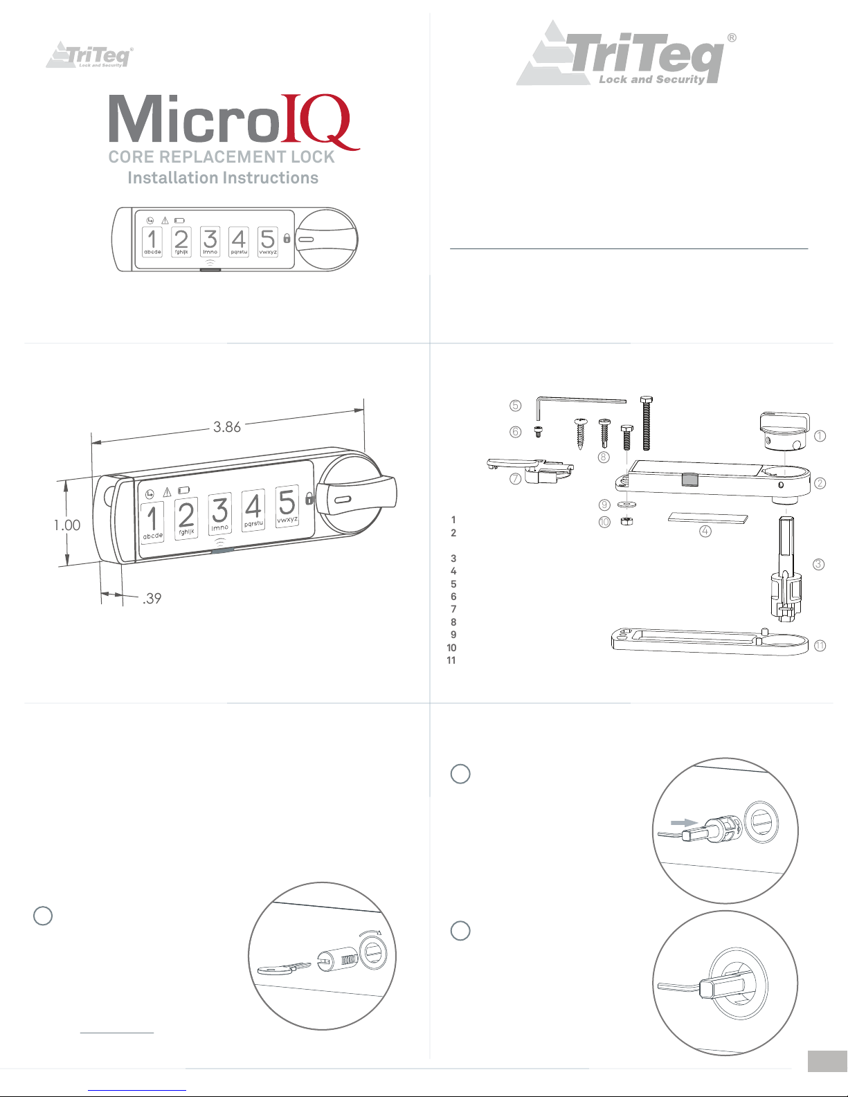
.39
1.00
3.86
11
1
2
3
4
5
6
7
8
9
10
11
1
9
10
4
2
3
5
6
7
8
www.microiqlock.com
Steelcase
FOR OFFICE FURNITURE, STORAGE CABINETS, LOCKERS, SAFES, VAULTS, SECURED ENCLOSURES
General dimensions
TriTeq Lock and Security
701 Gullo Ave
Elk Grove Village, IL 60007
© Copyright 2014 TriTeq Lock and Security. All rights reserved062415 - Rev. 6
#4 #4
M2
Knob
Lock Housing with keypad
and infrared receiver
Spindle
3M - VHB 4952 Foam tape ( optional )
Hex tool (1.5 mm)
Temper proof battery holder screw
CR2032 - 3 Volt Lithium Battery and battery holder
Mounting screws ( select one )
Mounting washer
Mounting nut
0.1” or 0.187” Spacers ( optional )
M3
Email: [email protected]
M3
Phone: (847) 640-7002
Toll Free: (888) 603-5625
Fig. 1
Installation
See Figure 1 for available mounting hardware for the MicroIQ. When mounting the MicroIQ to a
cabinet door or drawer, the existing handle should be used to operate, open and close the door
or drawer.
Additional mounting fasteners ( item 10 ) are provided and must be added through the battery
extremity of the housing. Select the fasteners that best fit your panel material and thickness.
If drilling is required for thick panels use the drilling template provided at the end of this
manual. Double sided tape is also provided.
1
Using your change key, turn the lock to
the extreme CW position and remove the
lock core.
Note the position of the retaining
tumbler on the lock core removed
i.e.: 12 o`clock, 3, 6 or 9 o`clock position.
You can purchase the change key online
at :
www.easykeys.com
Example:
3 o`clock position
Rotate CW
Push the hex tool into the spindle
2
slot and move the tool toward the
spindle shaft until the upper edge
of the retaining tumbler is retracted.
Insert the spindle with the retaining
tumbler at the same orientation as
the lock core that was removed,
such as 3 o’clock in this example.
While holding the spindle in,
3
remove the hex tool.
Confirm that the spindle is
engaged into the lock shell.
1
Page 2
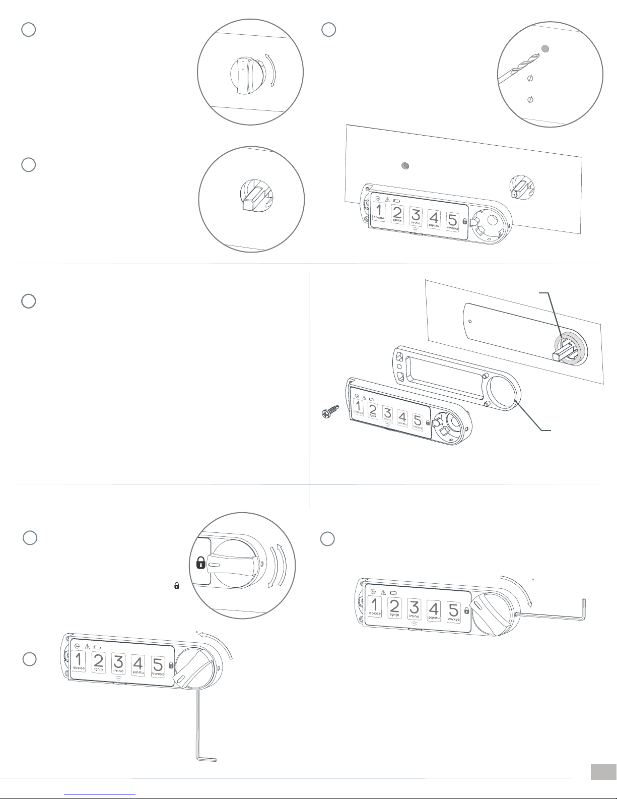
Insert the knob. Exercise the knob and verify
4
that the spindle is engaged and operates
your locking mechanism as intended.
Remove the knob from the spindle with
5
the mechanism in the locked position.
6
The MicroIQ can be mounted with the
enclosed screw or double stick tape or both.
The installation template at the end of this
manual can be used to drill the mounting hole
for the MicroIQ. A wood screw and a
self-tapping metal screw are provided.
Fig. 2
1/8” diameter hole
for metal
3/32” diameter
hole for wood
If the lock shell has a non-removable finish cup or a collar/bezel that would
7
restrict the
appropriate lock spacer in between the
0.1” (
The spacers are available in chrome and black finish. To select your preffered
finish, add the letter “C” for chrome or “B” for black to the end of the part
number. (e.g.: 13081-00-C )
Select appropriate mounting screw. If a lock spacer is required, a mounting
screw must be used.
Mount as shown in Fig. 2.
Remove the backing from the foam tape (underneath the lock body) and insert
the MicroIQ in the desired orientation until it is flush with the face of your panel.
Allow tape to cure for 72 hours.
Insert the knob and push until flush inside
8
housing at locked position and rotate to verify
that the cam stop was positioned correctly.
MicroIQ from being inserted flush to the cabinet, use an
MicroIQ and the cabinet. Spacers of
P/N: 13081-00 ) and 0.187” ( P/N: 13081-10 ) are available from TriTeq.
Confirm that your mechanism is locked
when the knob points to the lock icon
Bezel
If your locking mechanism requires the knob to rotate CW from “locked” to
10
“unlocked”, rotate your knob only 45°. Using the hex tool, fasten the knob to the
spindle from the indicated location.
Lock
Spacer
45
45
9
If your locking mechanism requires the
knob to rotate CCW from “locked” to
“unlocked”, rotate your knob only 45° and
using the hex tool, fasten the knob to the
spindle from the indicated location.
Battery
The mounting screw for the lock housing must be installed before installing the
MicroIQ battery. Prior to installation and insertion of the battery, the knob of
the lock mechanism will be free moving.
After installing the lock to the mounting surface, the battery and holder can be
inserted into the lock. The cover for the battery holder also serves to lock the
holder into the lock housing. The battery cover must be in the fully open
position before inserting the holder. The battery holder screw cannot be
protruding from the bottom of the battery holder. It must be flush with the
holder so the holder can be inserted.
2
Page 3
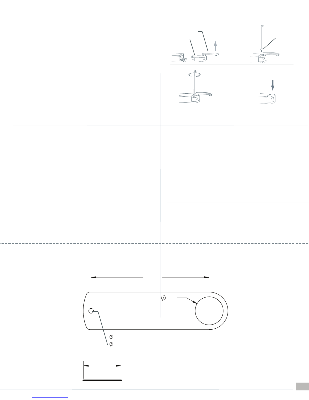
Check that the battery is properly inserted into the holder. The “+” surface of
the battery should be Inserted into the holder against the surface of the holder
marked with the “+” symbol. Insert the battery holder into the lock with the
holder cover in the fully open position and with the battery holder screw flush
to the bottom of the holder until the holder is fully seated. Next, use the hex
tool to fasten the battery holder screw into the lock body. Last, swing the
battery holder cover to the closed position, push in and fully seat the cover into
the battery holder until it is flush to the lock body.
If the battery is inserted while the knob is locked, you should hear the lock
mechanism click and the unit will lock. If the battery is inserted while the knob is
unlocked, after turning the knob to the locked position you should hear the lock
mechanism click and the unit will lock. If the unit will not lock after inserting the
battery, enter the factory code, move the knob to the unlocked position, and move
the knob to the locked position and you should hear the lock mechanism click and
the unit will lock. If the unit still does not lock, replace the battery.
ATTENTION:
Battery life may vary with battery brand and environmental conditions .
Cleaning and Care:
To clean the MicroIQ surface, apply a non-acid based cleaner to a
clean cotton cloth. Do not spray cleaner directly on the MicroIQ.
Wipe down the keypad and housing surface of excess cleaner.
Battery
1 2
Battery
Holder
Cover
LIFT
UPWARD
3 4
Hex
Tool
Battery
Cover
Screw
SWING OVER
AND SNAP THE
COVER DOWN
4
TriTeq Limited Warranty:
TriTeq offers a one year limited warranty on all products to be free
from manufacturing defects in materials and workmanship. This
limited warranty does not cover battery, lost combinations or damages
caused by improper mounting, operation or unreasonable use.
Liability Limits:
This is a limited warranty and in lieu of all other warranties
(including the implied warranties of merchantability and fitness of
use) and under no circumstances shall TriTeq Lock & Security or
Hudson Lock, LLC be liable for any incidental or consequential
damages or losses.
Mounting Template
3.150
Operating Temperature: 0 - +50 C
Storage temperature: -10 - +70 C
Operating Moisture: 20% - 80% Rh (without condensation)
Replacement Battery: 3 volt lithium CR2032
Battery Life: 5 years or more ( calculated at 20 uses per day )
.75
1.00
1/8” diameter hole for metal
3/32” diameter hole for wood
Measure before drilling.
If the length of the segment is dierent from 1.00"
the template dimensions will be scaLED accordingly
3
 Loading...