

Page 1
INSTALLATION / OPERATING MANUAL
Distributed by
High Speed Mini PTZ Camera
P/N : 388058205
PRINTED IN KOREA
Before attempting to connect or operate this product,
please read these instructions carefully and save this manual for future use
Page 2
1. PRECAUTIONS
1. 1 Important Safety Instruction ...................................................................................
3p.
1. PRECAUTIONSTABLE OF CONTENTS
1. 1 Important Safety Instruction
•
Read these instructions.
•
Pay attention on all the warnings.
2. GETTING STARTED
2. 1 Features ................................................................................................................
2. 2 Unpacking ..............................................................................................................
2. 3 Selection Flow ........................................................................................................
3. INSTALLATION
3. 1 Address / communication setting ...........................................................................
3. 2 Cable Connection ...................................................................................................
3. 3 Indoor Ceiling .......................................................................................................
3. 4 Indoor In Ceiling ....................................................................................................
3. 5 Outdoor (Ceiling Bracket) ......................................................................................
3. 6 Outdoor (Wall Bracket) ..........................................................................................
4. MAIN SETUP MENU
4. 1 Initialize .................................................................................................................
4. 2 Motion Menu ..........................................................................................................
4. 3 Dome Menu ...........................................................................................................
4. 4 Camera Menu ........................................................................................................
5. SPECIFICATION
5. 1 Camera Specification..............................................................................................
4p.
4p.
5p.
6p.
6p.
7p.
8p.
9p.
10p.
11p.
11p.
22p.
28p.
37p.
•
Follow all instructions.
•
Do not block any ventilation openings. Install in accordance with the manufacturer's instructions.
•
Do not dissemble or insert foreign objects.
•
Do not install near any heat sources such as radiation, beat registers, stoves, or other apparatus.
(Including amplifiers) that produce heat.
•
Do not aim the camera at the sun or any other strong light source.
•
Do not install the camera in intermittent lighting environments.
•
Only use attachments/accessories specified by the manufacturer.
•
Use only with the cart, stand, tripod, bracket, or table specified by the manufacturer, or sold with
the apparatus. When a cart is used, use caution when moving the cart/apparatus combination
to avoid injury from tip-over.
•
Refer all servicing to qualified service personnel. Servicing is required when the apparatus has been
damaged in any way, such as power-supply cord or plug is damaged, liquid has been spilled or
objects have fallen into the apparatus, the apparatus has been exposed to rain or moisture, does not
operate normally, or has been dropped.
•
Installation should be done only by qualified personnel and conform to all local codes.
•
Installation should be done in a place strong enough to hold it.
6. DIMENSION
6. 1 Dimension .............................................................................................................
High Speed Mini PTZ Camera
02
38p.
•
Use only installation methods and materials capable of supporting four times the maximum specified load.
•
To prevent damage from water leakage when installing a mount outdoors on a roof or wall,
apply sealant around the bolt holes between the mount and mounting surface.
•
These instructions are for use by qualified service personnel only. To reduce the risk of electric shock
do not perform any servicing other that contained in the operating instructions unless you are qualified
to do so.
•
Only use replacement parts recommended by manufacturer.
High Speed Mini PTZ Camera
03
Page 3
2. GETTING STARTED
Auto-Focus
- The camera adjusts the focus automatically while monitoring the screen continuously
in the auto mode. It built in 12x zoom lens, when used in combination with its 32x
digital zoom, the camera achieves a zooming capability of up to 384x.
ICR
- These cameras offer optimal sensitivity in both day- and night-shootingapplications.
AUTO Flip
- You can observe the moving object without reversing of the screen, by using this
AUTO FLIP function.
Wide Range Auto functions
- PRESET : Up to 255 programmable presets.
- TOUR : Up to 8 programmable Tours consisting of presets with individual dwell time.
- SCAN : Repeatedly pan & tilt operating between two positions. (Max.8)
- PATTERN : Up to 4 programmable Patterns memorizing the PTZ movement.
- AREA : Up to 16 programmable Area display sets.
- ALARM : Move the camera to programmed Presetposition with Alarm trigger.(Max.2)
- PRIVACY : Up to 8 programmable Privacy masking.
Multi protocol and communication method
- RS 422, RS485 support
- PELCO-D 5.0, PELCO-P, WTX, 2400 ~ 57600 Baudrate
WDR
- The camera delivers clear, high quality picture in backlight, by increasing exposure in
darkareas while decreasing it in bright areas a corrected image with clear details results.
Programmable zoom speed
- Zoom speed can be set and decide using of digital zoom function.
When this function is ON, the pan/tilt speed is inversely adjusted to the zoom ratio.
2. 3 Selection Flow2. 1 Features
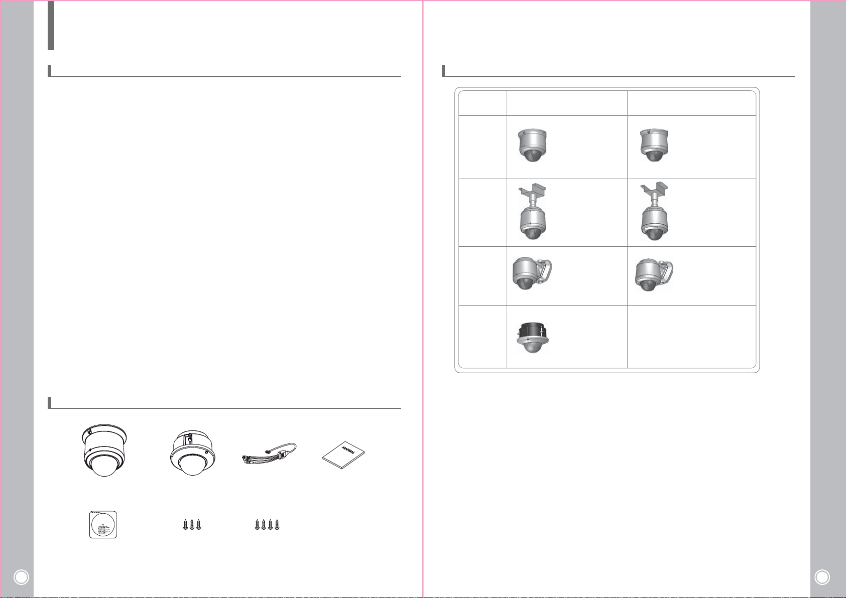
Surface
Ceiling
Wall
In-Ceiling
IndoorType
Indoor Ceiling
Indoor Ceiling_Pipe
(Pipe 200mm)
Indoor Wall
Indoor In Ceiling
Outdoor
Outdoor Ceiling
Outdoor Ceiling_Pipe
(Pipe 200mm)
Outdoor Wall
2. 2 Unpacking
(In-Ceiling Type)
High Speed Mini PTZ Camera
04
STICKER
Indoor In CeilingIndoor Ceiling / Outdoor Ceiling MAIN CABLE Manual
SCREW #8*38
(Surface Type)
SCREW #8*38
(Ceiling Type)
High Speed Mini PTZ Camera
05
Page 4
3.Installation
1286432168421
87654321
ONOFFONOFFONOFF5
OFFOFFONONOFFOFF4
ONONOFFOFFOFFOFF3
576003840019200960048002400S/W NO
ONOFF6
PALNTSCS/W NO
ONOFF7
RS485RS422S/W NO
ON
OFFOFF1
OFFONOFF2
S/W NO
PELCO-D V5.0
PELCO-P
WTX
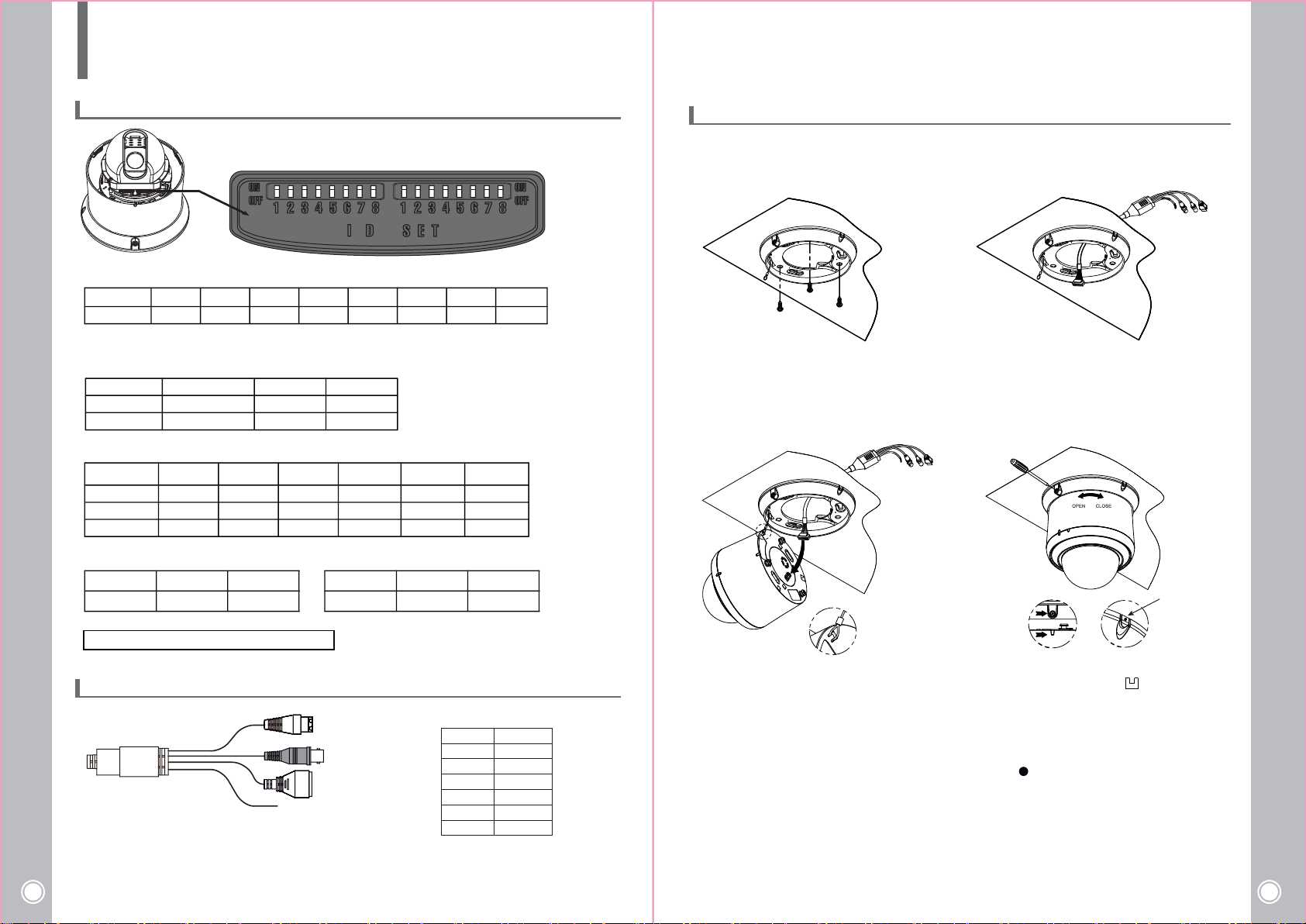
3. 1 Address / communication setting
▶ ADDRESS( ID) setting
S/W NO
HEX
▶ SETTING
PROTOCOL setting
PELCO-D V5.0
▶Baudrate setting
▶NTSC/PAL setting ▶Communication
PELCO-P
OFF
WTX
ON
OFF
3. 3 Indoor Ceiling
The following steps of installation and connection work should be done by qualified service personnel
or system installers and should conform to all local codes.
12
1
Make a Ø70 hole in the ceiling and install the bracket
by usning enclosed screws.(#8*38)
3
Pull out the main cable through the hole.
4
*No.8 SWITCH : For program input
3. 2 Cable Connection
1) Power cable connecting
- DC 12V type should be connected with + and - .correctly.
High Speed Mini PTZ Camera
06
- AC24V type can be connected with any direction.
* AC 24V 3A(OUTDOOR) * DC 12V 1.5A(INDOOR)
-
-
-
AC24V / DC12V
+
+-+
+-+-+
CVBS (YELLOW)
RX+
RXTX+
TX-
ALARM / AUX CABLE
* ALARM /AUX CABLE
BLACK
BROWN
RED
ORANGE
YELLOW
PURPLE
GRAY
GND
ALARM1
ALARM2
RY1 NO
RY2 NO
RY1 COM
RY2 COM
1. Connect the safety wire of mount bracket to the
camera base.
2. Connect the main cable.
1. Aline the mount bracket and position of the
body.
2. Attach the camera to the mount bracket by turning
CLOSE direction and tighten (up) a screw.
* If you want to pull out the cable to the side,
cut the part and pull out the cable.
High Speed Mini PTZ Camera
07
Page 5
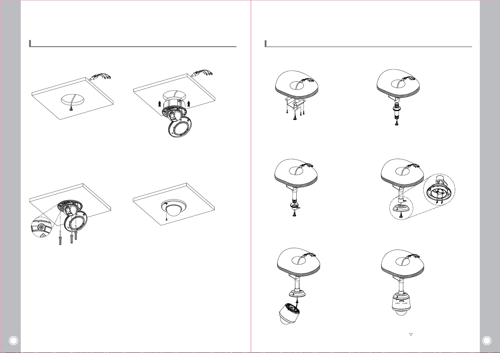
3. 4 Indoor In Ceiling
3. 5 Outdoor (Ceiling Bracket)
The mounting has to be installed onto a firm and stable location where all the parts may be completely
secured. The installation needs to be performed by a trained and experienced professional.
12
1. Make a Ø165 hole in the ceiling.
2. Pull out the main cable through the hole.
1. Connect the cable with the connector of the base.
2. Set the body into the hole.
34
The mounting has to be installed onto a firm and stable location where all the parts may be completely
secured. The installation needs to be performed by a trained and experienced professional.
12
1. Make a hole in the ceiling and pull out the main
cable through the hole.
2. Fix the plate ceiling by using #8x38 screws.
1. Pull out the main cable through the pipe ceiling.
2. Fix the pipe ceiling in the plate ceiling.
34
1. Fix the PTZ using the M4x7 bolts. 1.Assemble the dome cover on the PTZ and fix it
High Speed Mini PTZ Camera
08
by using the M3x6 screws.
2. Cover the rubber stopper after fixe the screws.
1.Fix the adapter flange in the pipe ceiling. 1. Fix the adaptor in the adapter flange by using
M4x10 screws.
56
1. Connect the cable with the connector of the base.
1. Align with the “ ” mark on the PTZ body and fix
the screw.
High Speed Mini PTZ Camera
09
Page 6
4. MAIN SETUP MENU
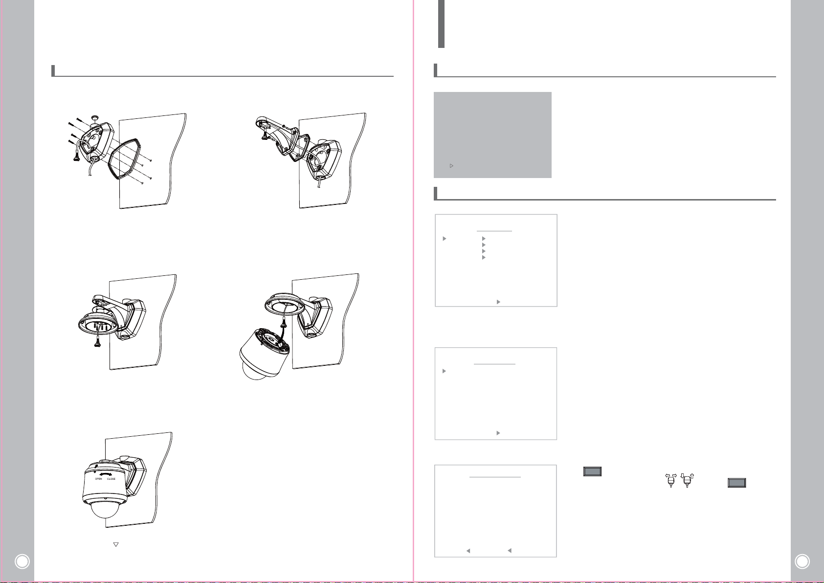
3. 6 Outdoor (Wall Bracket)
The mounting has to be installed onto a firm and stable location where all the parts may be completely
secured. The installation needs to be performed by a trained and experienced professional.
12
1. Attached the rubber on the adapter wall and fix it
on the wall by using #8x38 screws.
2. Pull out the main cable and cover the hole by using
‘bolt mount B type’.
3
1. Attach the rubber adapter on the adapter and fix it
with wall bracket by using M4x10 screws.
5
1. Attached the rubber on the bracket wall and fix it
with adapter wall by using security M5x20 screws.
2. Pull out the main cable through the bracket hole.
4
1. Connect the cable with the connector of the base.
4. 1 Initialize
INITIALIZE
ADDRESS
VERSION
VIDEO
PROTOCOL
BAUDRATE
>>PAN OFFSET . . . . . . . PASS
>>TILT OFFSET . . . . . . . PASS
>>CAMERA . . . . . . . . . . . PASS
: 001
: 1.05
: NTSC EMC EM123SN
: PELCO P
: 2400, N, 1
NORMAL SETTING WAIT...
4. 2 Motion Menu
MAIN MENU
MOTION
DOME
CAMERA
CLEAR
PTZ RESET
EXIT
< NEAR / RIGHT MOTION >
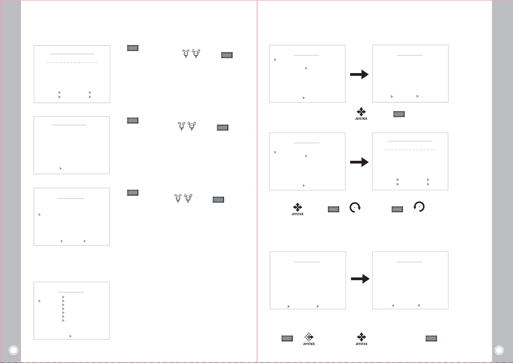
1) Set preset.
PRESET MENU
PRESET NO
LABEL
POSIRION
FOCUS
: 001 UNDEFINE
: PRESET 001
: 019.9, 005.4
: AUTO
SAVE CLR BACK EXIT
< NEAR / RIGHT PRESET NO >
When the device is powered on, you can check the address,
version, protocol and video setting values.
C : 1.06
ACH=CBA9BI
The preset function is that the camera memorizes positions
of the pan/tilt and zoom. This function is a representative
function of the speed dome which can find memorized
preset positions just by selecting the preset number.
Preset No. : Max. 255 positions can be stored and the each
position can be assigned as a defined Preset No.
Label : Each Preset can have its own label name.
Position : It displays the coordinates to position the assigned
Preset.
Focus : It enables to set the camera focus for each Preset
position.
High Speed Mini PTZ Camera
10
1. Align with the “ ” mark on the PTZ body and fix
the screw.
- Set PRESET Number
PRESET SELECT 1
P001
P002
P003
P004
P007
P008
014
020
026
032
038
044
050
009
015
021
027
033
039
045
051
013
019
025
031
037
043
049
< SEL NEAR/MOVE JOYSTICK >
010
016
022
028
034
040
046
052
P005
011
017
023
029
035
041
047
053
P006
012
018
024
030
036
042
048
054
NEAR
Press key.
Select number by using joystick and press key.
NEAR
High Speed Mini PTZ Camera
11
Page 7
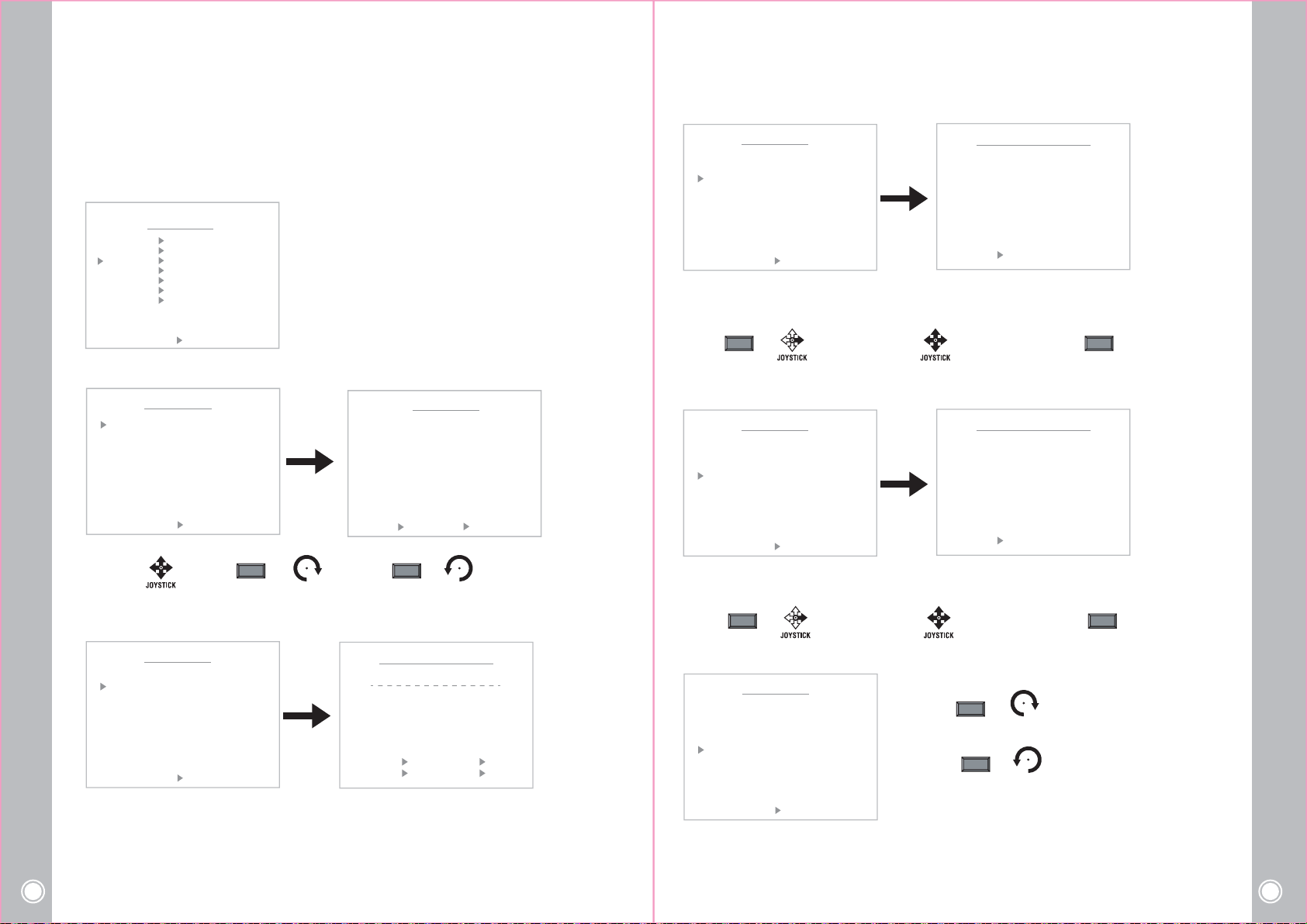
- LABEL Setting
PRESET LABEL EDIT <001>
LABEL : PRESET 001
0
1
2
3
)
L
M
X
Y
4
A
B
C
D
E
N
O
P
Q
Z
.
/
,
- TOUR NO
NEAR
Press key.
Select character by using joystick and press key.
5
6
7
8
9
F
R
+
(
G
H
I
J
K
S
T
U
V
W
-
=
<
>
@
NEAR
TOUR NO
LABEL
TOUR EDIT
TOUR MENU
: 01 DEFINE
:
T01
07
TOUR MENU
03 04 05 06
T02
08
<STORE TELE MOVE JOY >
<DEL WIDE BACK NEAR>
- POSITION Setting
LABEL : PRESET 001
POSITION : 019 .9, 005.4
< EXIT FOCUS NEAR >
- FOCUS Setting
PRESET NO
LABEL
POSIRION
FOCUS
SAVE CLR BACK EXIT
< CHANGE UP/DN SEL NEAR >
2) TOUR
The Tour function consists of several presets run by turn.
Maximum of 8 Tour functions are toured in order.
PRESET
TOUR
SCAN
PATTERN
AREA
ALARM
PRIVACY
EXIT BACK
High Speed Mini PTZ Camera
12
< NEAR / RIGHT TOUR >
PRESET POSITION
PRESET MENU
: 001 DEFINE
: PRESET 001
: 019.9, 005.4
: AUTO
MOTION MENU
NEAR
Press key.
Select number by using joystick and press key.
NEAR
Press key.
Select focus by using joystick and press key.
NEAR
NEAR
AUTO / MANUAL / ONE SHOT
SAVE CLR BACK EXIT
< NEAR / RIGHT TOUR NO >
Select the Tour number
Move : Select :
< SEL NEAR/MOVE JOYSTICK >
NEAR
- LABEL
TOUR MENU
TOUR NO
LABEL
TOUR EDIT
SAVE CLR BACK EXIT
< NEAR / RIGHT TOUR NO >
: 01 DEFINE
:
TOUR LABEL EDIT <01>
LABEL
0
1
2
3
4
5
6
7
8
)
A
B
C
D
L
M
X
<STORE TELE MOVE JOY >
<DEL WIDE BACK NEAR>
E
N
O
P
Q
Y
Z
.
/
,
9
F
G
H
I
J
R
S
T
U
V
+
-
=
<
>
Set the Tour Label
Move : Select : or or
TELE WIDE
JOYSTICK
Delete : or
JOYSTICK
It’s available to set the desired label, displayed on the executing screen of Tour.
After the label is set, push the NEAR button to exit.
- TOUR EDIT
013
019
025
031
037
043
049
P002
P008
014
020
026
032
038
044
050
TOUR MENU
P004
P003
010
009
016
015
022
021
028
027
034
033
040
039
046
045
052
051
P005
011
017
023
029
035
041
047
053
TOUR MENU
NO
PRESET
SPEED
01
P001
02
P002
03
P003
04
P004
05
P005
06
P006
07
P007
08
P008
SAVE CLR BACK EXIT
< SEL NEAR PRESET LEFT >
DWELL
63
02
63
02
63
02
63
02
63
02
63
02
63
02
63
02
P001
P007
< SEL NEAR/MOVE JOYSTICK >
Define the Preset position
a. Move to the set-up window
NEAR NEAR
or
b. Move and set the position c. Set & Back
(
K
W
@
P006
012
018
024
030
036
042
048
054
High Speed Mini PTZ Camera
13
Page 8
3) Scan
By using Scan function, the camera moves between 2 positions if there is no PTZ command
passing the assigned Dwell time. When there is no camera movement, the Scan function
camera moves from the position assigned as the start point to the position
assigned as the end point
in CW (Clockwise) direction.
MOTION MENU
PRESET
TOUR
SCAN
PATTERN
AREA
ALARM
PRIVACY
EXIT BACK
< NEAR / RIGHT SCAN >
- SCAN NO
SCAN MENU
SCAN NO
LABEL
START POS
END POS
SPEED
DWELL
FOCUS
SAVE CLR BACK EXIT
< NEAR / RIGHT SCAN >
: 01 UNDEFINE
:
: XXX.X, XXX.X
: XXX.X, --: XX
: XX
: NONE
Move : Select : or or
- Scan No. : Max. 8 Scans can be stored.
- Label : The each Tour can have its own label name.
- Start position : Assign the coordinate of the Scan star ting
position.
- End position : Assign the coordinate of the Scan ending position.
- Move Speed : It enables to set the running speed in the each
coordinate.(1~63)
- Dwell : The Scan function runs after the Dwell time without any
camera movement.
- Focus : It enables to set the camera Focus.
SCAN MENU
01 02 03 04 05 06
07 08
< SEL NEAR/MOVE JOYSTICK >
TELE WIDE
Delete : or
JOYSTICK
JOYSTICK
after
runs and the
- Start POSITION
SCAN MENU
SCAN NO
LABEL
START POS
END POS
SPEED
DWELL
FOCUS
SAVE CLR BACK EXIT
< NEAR / RIGHT START POS >
: 01 DEFINE
:
: 000.0, 000.0
: 000.0, --: 60
: 02
: AUTO
SCAN START POSITION
POSITION : 000 .0, 000 .0
< EXIT FOCUS NEAR >
Define the Start pan position
① Select Start Pos menu
NEAR NEAR
or
- END POSITION
SCAN MENU
SCAN NO
LABEL
START POS
END POS
SPEED
DWELL
FOCUS
SAVE CLR BACK EXIT
< NEAR / RIGHT END POS >
: 01 DEFINE
:
: 000.0, 000.0
: 000.0, --: 60
: 02
: AUTO
② Move and set the position ③ Go back
SCAN END POSITION
POSITION : 000 .0
< EXIT FOCUS NEAR >
Define the End pan position
① Select End Pos menu
② Move and set the position ③ Go back
- LABEL
SCAN NO
LABEL
START POS
END POS
SPEED
DWELL
FOCUS
SAVE CLR BACK EXIT
< NEAR / RIGHT LABEL SEL >
It’s available to set the desired label, displayed on the executing screen of Scan.
After the label is set, push NEAR button to go out.
High Speed Mini PTZ Camera
14
SCAN MENU
: 01 UNDEFINE
:
: XXX.X, XXX.X
: XXX.X, --: XX
: XX
: NONE
SCAN LABEL EDIT <01>
LABEL :
0
1
2
3
4
5
6
7
8
9
)
A
B
C
D
E
L
M
X
Y
<STORE TELE MOVE JOY >
<DEL WIDE BACK NEAR>
F
N
O
P
Q
R
Z
.
/
,
+
(
G
H
I
J
K
S
T
U
V
W
-
=
<
>
@
NEAR NEAR
or
- SPEED
SCAN MENU
SCAN NO
LABEL
START POS
END POS
SPEED
DWELL
FOCUS
SAVE CLR BACK EXIT
< NEAR / RIGHT MOVE SPEED >
: 01 DEFINE
:
: 000.0, 000.0
: 000.0, --: 60
: 02
: AUTO
Set the Scan speed
Increase : or
Decrease : or
TELE
JOYSTICK
WIDE
JOYSTICK
It adjusts the moving speed from 0~63 steps.
High Speed Mini PTZ Camera
15
Page 9
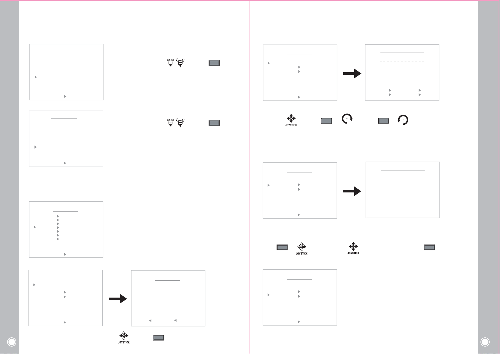
- DWELL
SCAN MENU
SCAN NO
LABEL
START POS
END POS
SPEED
DWELL
FOCUS
SAVE CLR BACK EXIT
< NEAR / RIGHT DWELL >
: 01 DEFINE
:
: 000.0, 000.0
: 000.0, --: 60
: 02
: AUTO
- FOCUS
SCAN MENU
SCAN NO
LABEL
START POS
END POS
SPEED
DWELL
FOCUS
: 01 DEFINE
:
: 000.0, 000.0
: 000.0, --: 60
: 02
: AUTO
The Scan function runs after the Dwell time without any camera
movement.
Select ON/OFF by using joystick and press key.
NEAR
It enables to set the camera Focus.
Select ON/OFF by using joystick and press key.
NEAR
- LABEL
PATTERN MENU
PATTERN NO
LABEL
RECORD
PLAY
SAVE CLR BACK EXIT
< NEAR / RIGHT LABEL SEL >
: 01 UNDEFINE
:
PATTERN LABEL EDIT <01>
LABEL :
0
1
2
3
4
5
6
7
8
9
)
A
B
C
D
E
L
M
X
Y
<STORE TELE MOVE JOY >
<DEL WIDE BACK NEAR>
F
N
O
P
Q
R
Z
.
/
,
+
(
G
H
I
J
K
S
T
U
V
W
-
=
<
>
@
Set the Pattern Label
Move : Select : or or
TELE WIDE
Delete : or
JOYSTICK
JOYSTICK
It’s available to set the desired label, displayed on the executing screen of Pattern.
After the label set, push NEAR button to go out.
SAVE CLR BACK EXIT
< NEAR / RIGHT FOCUS MODE >
4) PATTERN
The Pattern function memorizes User’s random moving path and zoom ratio.
Total recording time limit is 90secs and maximum 2 Pattern functions are toured in order.
MOTION MENU
PRESET
TOUR
SCAN
PATTERN
AREA
ALARM
PRIVACY
EXIT BACK
< NEAR / RIGHT PATTERN >
- PATTERN NO
PATTERN MENU
PATTERN NO
LABEL
RECORD
PLAY
SAVE CLR BACK EXIT
< NEAR / RIGHT PATT NO >
: 01 UNDEFINE
:
*PATTERN NO : 1~4 Patterns can be stored in Keyboard menu.
*LABEL : The each Pattern can have its own label name.
*RECORD : Movement by joystick and preset movement can be
memorized in a pattern.
*PLAY : To revive the Pattern during the recorded time.
PATTERN MENU
01 02 03 04
< SEL NEAR/MOVE JOYSTICK >
- RECORDING
PATTERN MENU
PATTERN NO
LABEL
RECORD
PLAY
SAVE CLR BACK EXIT
< NEAR / RIGHT RECORD >
: 01 DEFINE
:
<00SEC>
PATTERN RECORD
EXIT : NEAR 005 .8,000 .0
Record and Save the User’s random Pattern data
① Select the “Record” Menu
NEAR NEAR
or
- PLAY
PATTERN MENU
PATTERN NO
LABEL
RECORD
PLAY
SAVE CLR BACK EXIT
< NEAR / RIGHT PLAY >
: 01 DEFINE
:
<00SEC>
② Move and record the pattern ③ Set & Back
Play back the recorded Pattern data
03/60
High Speed Mini PTZ Camera
Select the Pattern number
16
Move : Select :
NEAR
High Speed Mini PTZ Camera
17
Page 10
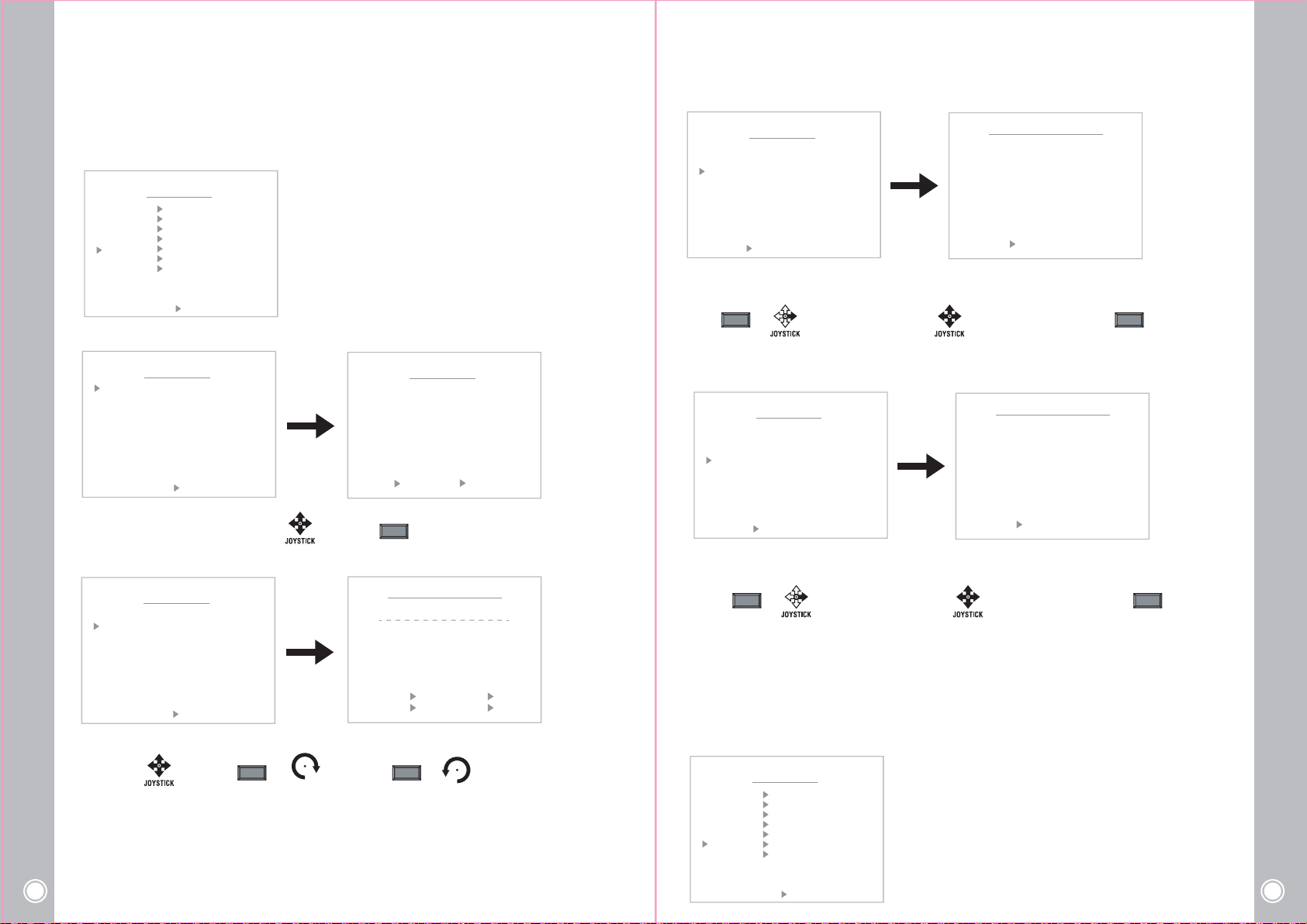
5) AREA
The Area function means that it displays the Area name between two programmed pan positions.
Maximun 16 Area functions are toured in order.
PRESET
TOUR
SCAN
PATTERN
AREA
ALARM
PRIVACY
EXIT BACK
< NEAR / RIGHT AREA >
- AREA NO
AREA NO
LABEL
START PAN POS
STOP PAN POS
SAVE CLR BACK EXIT
< NEAR / RIGHT AREA NO >
Select the Area number
- LABEL
AREA NO
LABEL
START PAN POS
STOP PAN POS
SAVE CLR BACK EXIT
< NEAR / RIGHT LABEL EDIT >
Set the Area Label
Move : Select : or or
After the label set, push NEAR button to go out.
High Speed Mini PTZ Camera
18
MOTION MENU
AREA MENU
: 01 UNDEFINE
:
: XXX.X
: XXX.X
AREA MENU
: 01 UNDEFINE
:
: XXX.X
: XXX.X
Move : Select :
TELE WIDE
JOYSTICK
Delete : or
AREA SELECT
01 02 03 04 05
06 07 08 09 10
11 12 13 14 15
16
< SEL NEAR/MOVE JOYSTICK >
NEAR
AREA LABEL EDIT <01>
LABEL :
0
1
2
3
4
5
6
7
8
9
)
A
B
C
D
E
L
M
N
X
Y
<STORE TELE MOVE JOY >
<DEL WIDE BACK NEAR>
F
O
P
Q
R
Z
.
/
,
+
JOYSTICK
(
G
H
I
J
K
S
T
U
V
W
-
=
<
>
@
- START PAN POSITION
AREA MENU
AREA NO
LABEL
START PAN POS
STOP PAN POS
SAVE CLR BACK EXIT
< MOVE NEAR / JOYSTICK>
: 01 DEFINE
:
: 000.0
: 000.0
AREA START POSITION
POSITION : 000 .0, 000 .0
< EXIT FOCUS NEAR >
Define the Start pan position
① Select the “Start Pan Pos” menu
NEAR NEAR
or
※
Camera will move to clockwise direction only when START setting.
- STOP PAN POSITION
AREA MENU
AREA NO
LABEL
START PAN POS
STOP PAN POS
SAVE CLR BACK EXIT
< MOVE NEAR / JOYSTICK>
: 01 DEFINE
:
: 000.0
: 000.0
② Move and set the position ③ Set & Back
AREA STOP POSITION
POSITION : 000 .0, 000 .0
< EXIT FOCUS NEAR >
Define the Stop pan position
① Select the “Start Pan Pos” Menu
NEAR NEAR
or
※ “Save” above setting Area data to the memory.
② Move and set the position ③ Set & Back
- "Save" above setting data to the memory.
- "CLR" means above setting Pattern data will not be saved and be cleared.
- "BACK" means it goes back to the previous menu.
- "EXIT" means it goes out of the MENU
6) ALARM
The Alarm function means that the camera moves to the programmed Preset position by the Alarm
trigger. Maximum 2 Alarm functions are toured in order.
MOTION MENU
PRESET
TOUR
SCAN
PATTERN
AREA
ALARM
PRIVACY
EXIT BACK
< NEAR / RIGHT ALARM >
*ALARM NO : 1~2 Alarms can be stored.
*LABEL : The each Alarm can have its own label name.
*PRESET NO : Assign the Preset No. to run when alarm is triggered.
High Speed Mini PTZ Camera
19
Page 11
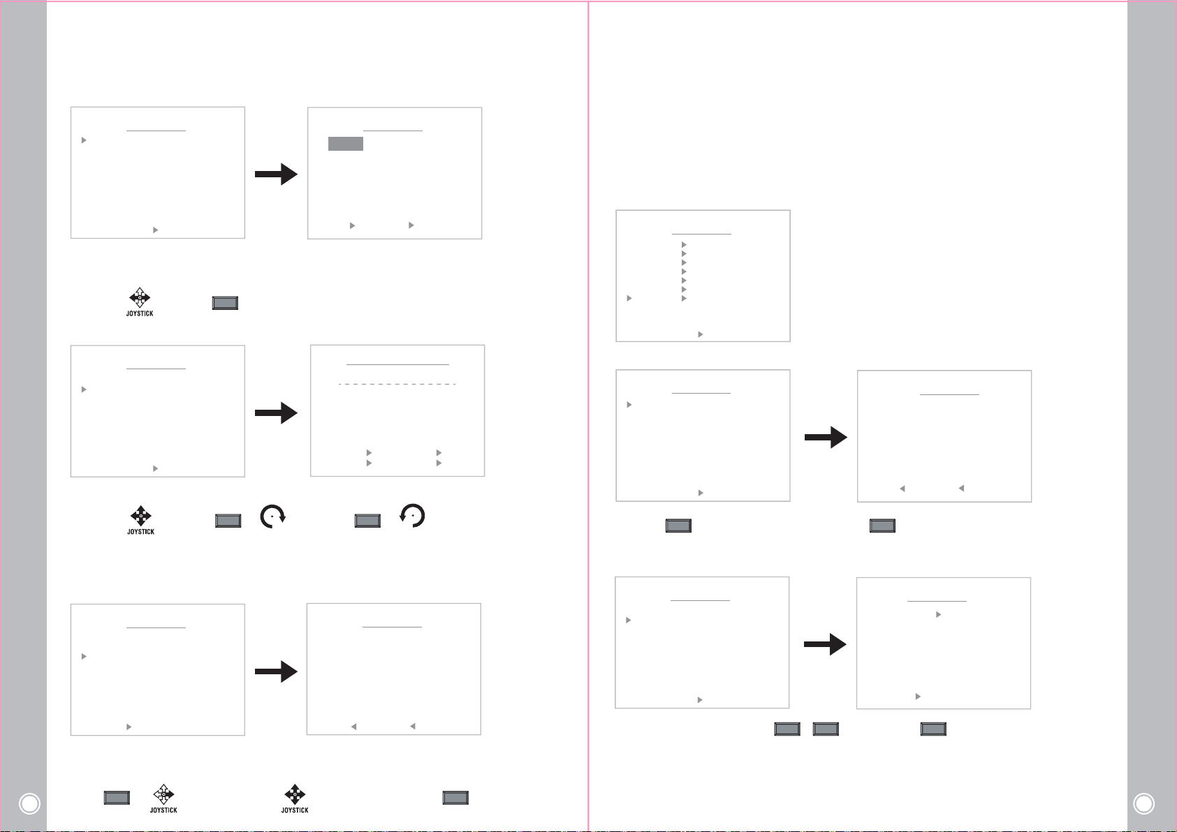
- ALARM NO
AREA MENU
ALARM NO
LABEL
PRESET NO
SAVE CLR BACK EXIT
< NEAR / RIGHT ALRAM NO >
: 01 UNDEFINE
:
: XXX.X
ALARM SELECT
01
< SEL NEAR/MOVE JOYSTICK >
02
The Alarm function means that the camera moves to the programmed Preset position by the Alarm trigger.
Maximum 2 Alarm functions are toured in order.
Move : Select :
- LABEL
AREA MENU
ALARM NO
LABEL
PRESET NO
: 01 UNDEFINE
:
: XXX.X
NEAR
ALARM LABEL EDIT <01>
LABEL :
0
1
2
3
4
)
A
L
M
X
Y
5
B
C
D
E
F
N
O
P
Q
R
Z
.
/
,
+
6
7
8
9
(
G
H
I
J
K
S
T
U
V
W
-
=
<
>
@
※
“Save” above setting Alarm data to the memory.
- "Save" above setting data to the memory.
- "CLR" means above setting Pattern data will not be saved and be cleared.
- "BACK" means it goes back to the previous menu.
- "EXIT" means it goes out of the MENU
7) PRIV ACY setting
MOTION MENU
PRESET
TOUR
SCAN
PATTEN
AREA
ALARM
PRIVACY
EXIT BACK
< NEAR / RIGHT PRIVACY >
- PRIVACY NO
PRIVACY MENU
PRIVACY NO
POSITION
: 01 UNDEFINE
: XXX .X, XXX .X
*PRIVACY NO : To protect privacy, Max. 8 Privacy can be created
on the arbitrary position to hide objects such as windows, shops
or private house. With spherical coordinates system, powerful
privacy zone masking function is possible.
*POSITION : Adjust the mask position
PRIVACY SELECT
01 02 03 04 05
06 07 08
SAVE CLR BACK EXIT
< NEAR / RIGHT LABEL EDIT >
Set the Alarm Label
Move : Select : or or
It’s available to set the desired label, displayed on the executing screen of Alarm.
After the label is set, push the NEAR button to exit.
- PRESET NO
ALARM NO
LABEL
PRESET NO
SAVE CLR BACK EXIT
< MOVE NEAR / JOYSTICK>
Define the Preset position with Alarm trigger
① Select the “Preset No”
High Speed Mini PTZ Camera
20
NEAR NEAR
ALARM MENU
: 01 DEFINE
:
: 001
or
<STORE TELE MOVE JOY >
<DEL WIDE BACK NEAR>
TELE WIDE
JOYSTICK
Delete : or
JOYSTICK
PRESET SELECT 1
P001P002P003P004P005P006
P007P008 009 010 011 012
013 014 015 016 017 018
019 020 021 022 023 024
025 026 027 028 029 030
031 032 033 034 035 036
037 038 039 040 041 042
043 044 045 046 047 048
049 050 051 052 053 054
< SEL NEAR/MOVE JOYSTICK >
② Move and set the position ③ Set & Back
SAVE CLR BACK EXIT
< NEAR / RIGHT PRIVACY NO >
* Press key to set privacy number and press key again to go out the menu.
NEAR NEAR
< SEL NEAR/MOVE JOYSTICK >
- POSITION
PRIVACY MENU
PRIVACY NO
POSITION
SAVE CLR BACK EXIT
< NEAR / RIGHT PRIVACY NO >
*Ajust masking size by using , keys and press key to go out the menu.
: 01 DEFINE
: 000 .0, 000 .0
OPEN CLOSE NEAR
PRIVACY POSITION
MASK SIZE <OPEN/CLOSE>
POSITION : 000 .0, 000 .0
< EXIT FOCUS NEAR >
High Speed Mini PTZ Camera
21
Page 12
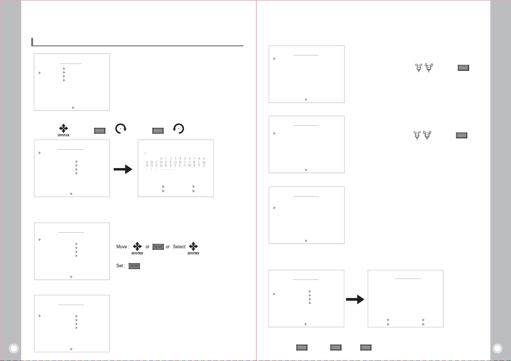
4. 3 Dome Menu
MAIN MENU
MOTION
DOME
CAMERA
CLEAR
PTZ RESET
EXIT
< NEAR / RIGHT DOME >
1) Set the Dome camera title
Move : Select : or or Delete : or
DOME MENU
TITLE :
POWER UP ACTION : ON
PARK ACTION
DISPLAY ON/OFF
DOME SUB MENU
TEMP SET MENU
FACTORY SET
SAVE CLR BACK EXIT
< NEAR / RIGHT TITLE SET >
After the label set, push NEAR button to go out.
2) POWER UP ACTION
DOME MENU
TITLE :
POWER UP ACTION : ON
PARK ACTION
DISPLAY ON/OFF
DOME SUB MENU
TEMP SET MENU
FACTORY SET
SAVE CLR BACK EXIT
< NEAR / RIGHT FUNCTION >
3) PARK ACTION
DOME MENU
TITLE :
POWER UP ACTION : ON
PARK ACTION
DISPLAY ON/OFF
DOME SUB MENU
TEMP SET MENU
FACTORY SET
High Speed Mini PTZ Camera
22
SAVE CLR BACK EXIT
< NEAR / RIGHT SUB MENU >
Pan, Tilt, Zoom motion is adjustable in the “Dome Setting” Menu.
TELE WIDE
JOYSTICK JOYSTICK
LABEL :
<STORE TELE MOVE JOY >
<DEL WIDE BACK NEAR>
TITLE SET
When this function is ON, the camera memorize the latest action
and restore it from sudden power failure.
:
This function enables to locate the camera to specific position
automatically if operator doesn’t
operate the controller for a while.
- TIME
PARK MENU
TIME
FUNCTION
NUMBER
SAVE BACK
< NEAR / RIGHT PARK TIME >
: 02MIN
: PRESET
: 01
*TIME (MIN) :
60sec. (Max. 2min./ by 10 sec.)
Select ON/OFF by using joystick and press key.
The Park time can be assigned from 10 sec to
- FUNCTION
:
PARK MENU
TIME
FUNCTION
NUMBER
SAVE BACK
< NEAR / RIGHT FUNCTION >
: 02MIN
: PRESET
: 01
Can select one of the motion functions, Preset, Tour, Pattern
and Scan.
Select ON/OFF by using joystick and press key.
- NUMBER
:
The number of selected motion function.
- PRESET : 01~255
- TOUR : 01~08
- SCAN :01 ~ 08
TIME
FUNCTION
NUMBER
PARK MENU
: 02MIN
: PRESET
: 01
- PATTERN : 01 ~ 04
SAVE BACK
< NEAR / RIGHT NUMBER >
※ When MOTION is operating, PARK ACTION is not working. (without AREA and PRIVACY )
4) DISPLAY ON/OFF
DOME MENU
TITLE :
POWER UP ACTION : ON
PARK ACTION
DISPLAY ON/OFF
DOME SUB MENU
TEMP SET MENU
FACTORY SET
SAVE CLR BACK EXIT
< NEAR / RIGHT SUB MENU >
DISPLAY ON/OFF SET
*
TITLE
< * >
ZOOM
< * >
PRESET
< * >
TOUR
< * >
SCAN
< * >
PRIVACY
< * >
PATTERN
< * >
AREA
<ON TELE MOVE JOY >
<OFF WIDE BACK NEAR>
ALARM
POSITION
ACTION
< * >
< * >
< >
You can select the OSD ON to shown on the screen or clear by selecting OFF in this function.
OSD ON : OSD OFF: Select :
NEARTELE WIDE
NEAR
NEAR
High Speed Mini PTZ Camera
23
Page 13
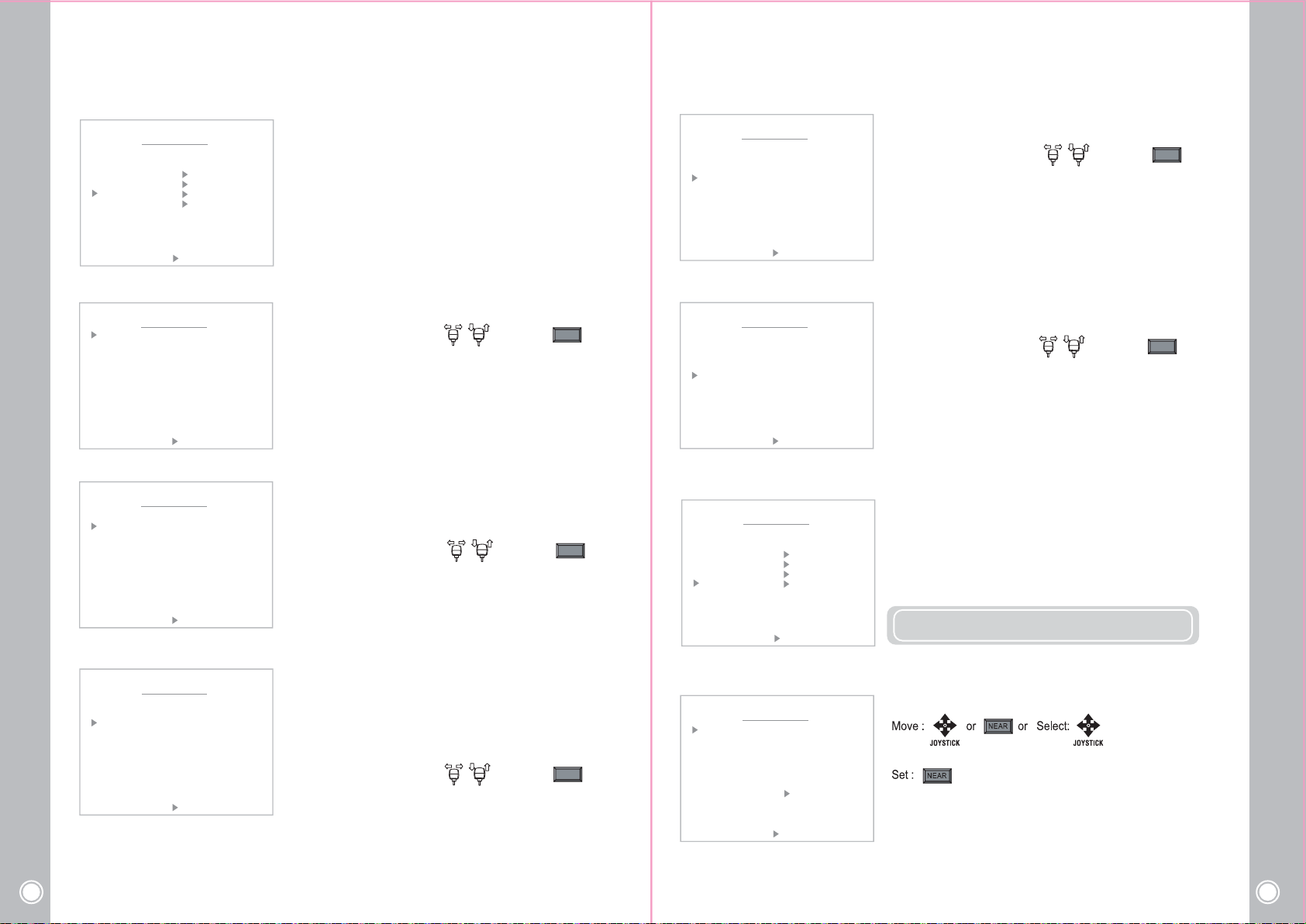
5) DOME SUB MENU
DOME MENU
TITLE :
POWER UP ACTION : ON
PARK ACTION
DISPLAY ON/OFF
DOME SUB MENU
TEMP SET MENU
FACTORY SET
- RESPONSE
DOME MENU
TILT LIMIT
SPEED BY ZOOM
AUTO FLIP
RESPONSE TXD
PRESER FREEZE
: OFF
: OFF
: OFF
: OFF
: OFF
*Send the intrinsic protocol value to the Tx line. (Only for Pelco-D 5.0)
Select ON/OFF by using joystick and press key.
NEAR
SAVE CLR BACK EXIT
< NEAR / RIGHT SUB MENU >
- TILT LIMIT
DOME MENU
TILT LIMIT
SPEED BY ZOOM
AUTO FLIP
RESPONSE TXD
PRESER FREEZE
SAVE BACK EXIT
< NEAR / RIGHT SUB MENU >
: OFF
: OFF
: OFF
: OFF
: OFF
- SPEED BY ZOOM
DOME MENU
TILT LIMIT
SPEED BY ZOOM
AUTO FLIP
RESPONSE TXD
PRESER FREEZE
SAVE BACK EXIT
< NEAR / RIGHT FUNCTION >
: OFF
: OFF
: OFF
: OFF
: OFF
- AUTO FLIP
DOME MENU
TILT LIMIT
SPEED BY ZOOM
AUTO FLIP
RESPONSE TXD
PRESER FREEZE
SAVE BACK EXIT
< NEAR / RIGHT FUNCTION >
: OFF
: OFF
: OFF
: OFF
: OFF
Set tilt stop angle. : off ~15°
Select ON/OFF by using joystick and press key.
NEAR
Pan and Tilt speed can be changed depending on zoom magnification.
ON will slow down the speed of Pan/Tilt and OFF will increase the
Pan/Tilt speed.
Select ON/OFF by using joystick and press key.
NEAR
- AUTO FLIP : In case that tilt angle arrives at the top of tilt orbit (90°),
zoom module camera keep moving to opposite tilt direction (180°) to
keep tracing targets. As soon as zoom module camera passes through
the top of tilt direction (90°), images should be reversed automatically and
appears in screen. If this function is set to OFF, tilt movement range is
0~90°
Select ON/OFF by using joystick and press key.
NEAR
SAVE BACK EXIT
< NEAR / RIGHT FUNCTION >
- PRESET FREEZE
DOME MENU
TILT LIMIT
SPEED BY ZOOM
AUTO FLIP
RESPONSE TXD
PRESER FREEZE
SAVE BACK EXIT
< NEAR / RIGHT FUNCTION >
6) TEMP SET
DOME MENU
TITLE :
POWER UP ACTION : ON
PARK ACTION
DISPLAY ON/OFF
DOME SUB MENU
TEMP SET MENU
FACTORY SET
SAVE CLR BACK EXIT
< NEAR / RIGHT SUB MENU >
- HEATER ON TEMP
DOME MENU
HEATER ON TEMP
HEATER ON TIME
HEATER OFF TEMP
FAN ON TEMP
FAN OFF TEMP
CURRENT TEMPER 50.06C
SAVE BACK EXIT
< NEAR / RIGHT ON TEMP >
: OFF
: OFF
: OFF
: OFF
: OFF
: 5 C
: 30 MIN
: 3O C
: 50 C
: 40 C
Video out for start & stop points only and during camera movement the screen
is shown paused image.
Select ON/OFF by using joystick and press key.
NEAR
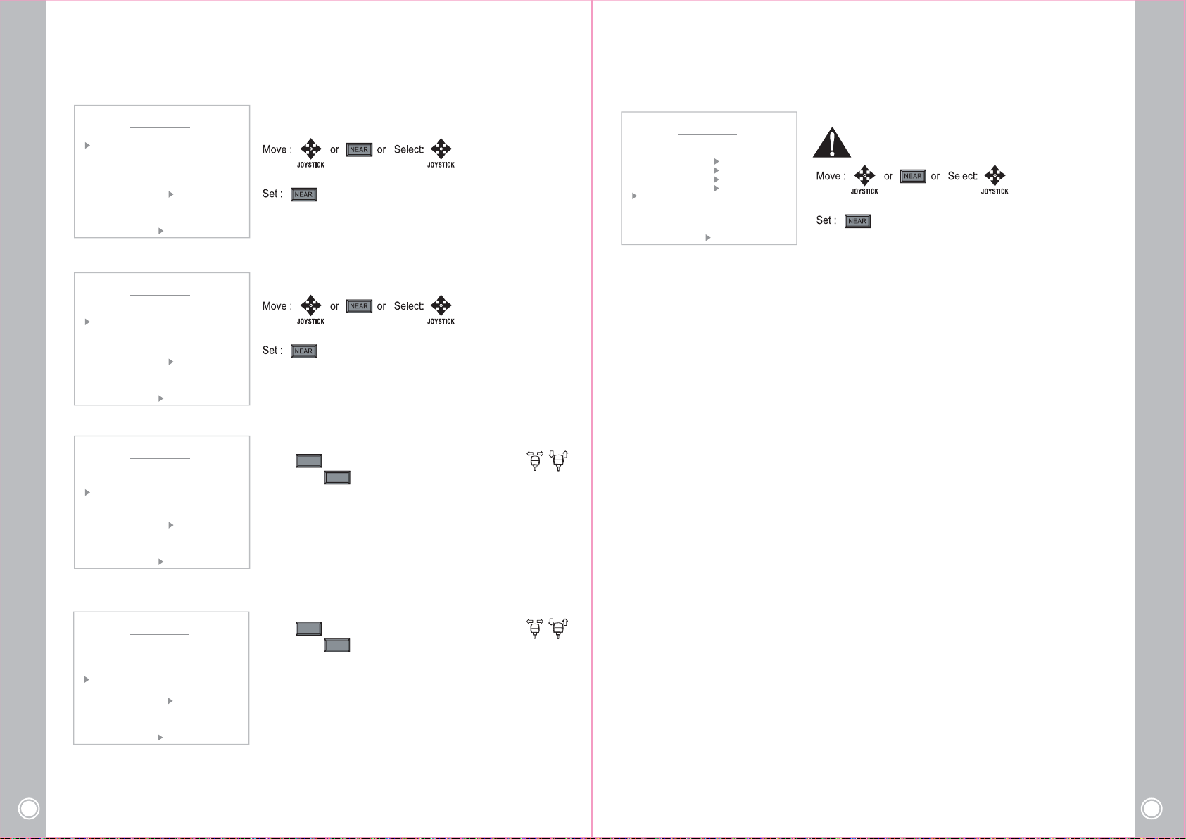
It shows you the current temperature and you can also set
the value manually. The compulsory Fan & Heater operation
is a useful function to remove humidity.
※ This function support outdoor product only.
*Set the operating temperature of the heater.(0~70℃)
High Speed Mini PTZ Camera
24
High Speed Mini PTZ Camera
25
Page 14
- HEATER ON TIME
DOME MENU
HEATER ON TEMP
HEATER ON TIME
HEATER OFF TEMP
FAN ON TEMP
FAN OFF TEMP
CURRENT TEMPER 50.06C
SAVE BACK EXIT
< NEAR / RIGHT ON TIME >
: 5 C
: 30 MIN
: 3O C
: 50 C
: 40 C
- HEATER OFF TEMP
DOME MENU
HEATER ON TEMP
HEATER ON TIME
HEATER OFF TEMP
FAN ON TEMP
FAN OFF TEMP
CURRENT TEMPER 50.06C
SAVE BACK EXIT
< NEAR / RIGHT OFF TEMP >
: 5 C
: 30 MIN
: 3O C
: 50 C
: 40 C
- FAN ON TEMP
DOME MENU
HEATER ON TEMP
HEATER ON TIME
HEATER OFF TEMP
FAN ON TEMP
FAN OFF TEMP
CURRENT TEMPER 50.06C
: 5 C
: 30 MIN
: 3O C
: 50 C
: 40 C
*Set the operating time of the heater.
- By 10min. (10~60 min.)
*Set the temperature of heater OFF. (0~70℃)
*Set the operating temperature of the Fan. (0~70℃)
NEAR
Press key and select the temperature by using
and press key again to go out the menu.
NEAR
7) FACTORY SET
DOME MENU
TITLE :
POWER UP ACTION : ON
PARK ACTION
DISPLAY ON/OFF
DOME SUB MENU
TEMP SET MENU
FACTORY SET
SAVE CLR BACK EXIT
< NEAR / RIGHT FUNCTION >
Restore all of setting value to the factory default.
All of existing setting value would be erased.
SAVE BACK EXIT
< NEAR / RIGHT FAN ON >
- FAN OFF TEMP
HEATER ON TEMP
HEATER ON TIME
HEATER OFF TEMP
FAN ON TEMP
FAN OFF TEMP
CURRENT TEMPER 50.06C
SAVE BACK EXIT
< NEAR / RIGHT FAN OFF >
High Speed Mini PTZ Camera
26
DOME MENU
: 5 C
: 30 MIN
: 3O C
: 50 C
: 40 C
* Set the temperature of Fan OFF. (0~70℃)
NEAR
Press key and select the temperature by using
and press key again to go out the menu.
NEAR
High Speed Mini PTZ Camera
27
Page 15
ઔ
ઔ
ઔ
ઔ
ઔ
4. 4 Camera Menu
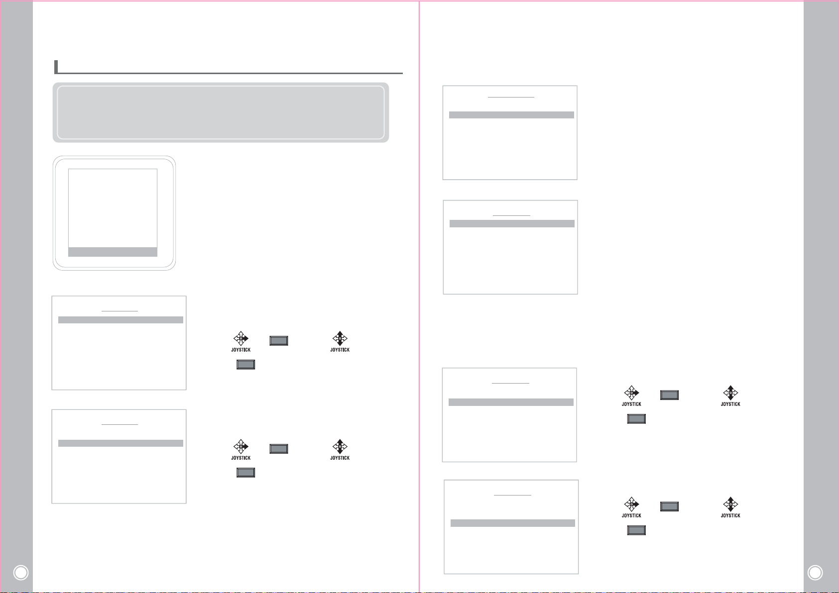
Camera menu is subject to change without prior notice to upgrade and quality increase and
we may use slip sheet for the change.
Please check the camera version and the slip sheet if the camera menu and this manual
menu is not matched.
6$9(%$&.(;,7
1($55,*+7ୄ=2206(7!
- ZOOM SPEED
ZOOM SPD : 7
D-ZOOM : ON
BACK
< NEAR / RIGHT ઔ ZOOM SPD>
- D-ZOOM
ZOOM SPD : 7
D-ZOOM : ON
BACK
< NEAR / RIGHT ઔ D-ZOOM >
D-ZOOM (Digital Zoom)
- Magnification of the Digital Zoom can be switched On and Off.
- It is recommended that the Digital Zoom should be set up before the preset operation.
High Speed Mini PTZ Camera
28
- As the digital zoom magnification increases, the image quality is lowered.
&$0(5$0(18
=22002'(
)2&8602'(
$(02'(
:%02'(
,&502'(
63(&,$/
&$05(6(7
ZOOM MENU
ZOOM MENU
2) FOCUS
In Focus menu, you can set up the focus mode among Auto, One Push or Manual.
CAMERA MENU
ZOOM MODE
FOCUS MODE
AE MODE
WB MODE
ICR MODE
SPECIAL
CAM RESET
1) ZOOM MODE
Zoom speed can be set and decided using of digital
zoom function.
SAVE BACK EXIT
< NEAR / RIGHT ઔ FOCUS SET >
- FOCUS MODE
FOCUS MODE : AUTO
FOCUS SPD : 5
NEAR LIMIT : XXXX
AF MODE : NORMAL
SENSITIVITY : NORMAL
ઔ
FOCUS MENU
AUTO: The camera adjusts the focus automatically while
monitoring the screen continuously in the auto mode.
In the auto focusing mode, zoom key operation is not
recognized as the input of the focus key.
One Push: It will be focused in about 5 seconds after zooming,
panning, and return to MANUAL mode automatically.
BACK
< NEAR / RIGHT ઔFOCUS MODE >
This is for focusing accurately after zooming.
Manual: In the manual mode, users can adjust the camera
ZOOM SPEED : Select from 1 step to 7 steps
USER (Standard speed)
Select : or Set ON :
Set OFF :
NEAR
NEAR
Decide using of digital zoom function.
D-ZOOM: ON/ OFF
Select : or Set ON :
Set OFF :
NEAR
NEAR
- FOCUS SPEED
FOCUS MENU
FOCUS MODE : MANUAL
FOCUS SPD : 3
NEAR LIMIT : 10CM
AF MODE : NORMAL
SENSITIVITY : NORMAL
BACK
< NEAR / RIGHT ઔFOCUS SPD >
- NEAR LIMIT
FOCUS MENU
FOCUS MODE : AUTO
FOCUS SPD :
NEAR LIMIT : 10CM
AF MODE : NORMAL
SENSITIVITY : NORMAL
BACK
< NEAR / RIGHT ઔNEAR LIMIT >
3
focus manually.
Infinity: infinity focus is the state where a lens forms an image
of an object an infinite distance away.
This corresponds to the point of focus for parallel rays.
Set the speed for camera focusing.
Select : or Set ON :
Set OFF :
NEAR
NEAR
Set the focus distance. (1.0 CM ~ OVERINF)
Select : or Set ON :
Set OFF :
NEAR
NEAR
High Speed Mini PTZ Camera
29
Page 16
ઔ
ઔ
ઔ
ઔ
ઔ
- AF MODE
FOCUS MENU
FOCUS MODE : AUTO
FOCUS SPD :
NEAR LIMIT : 10CM
AF MODE : NORMAL
SENSITIVITY : NORMAL
BACK
< NEAR / RIGHT ઔAF MODE >
3
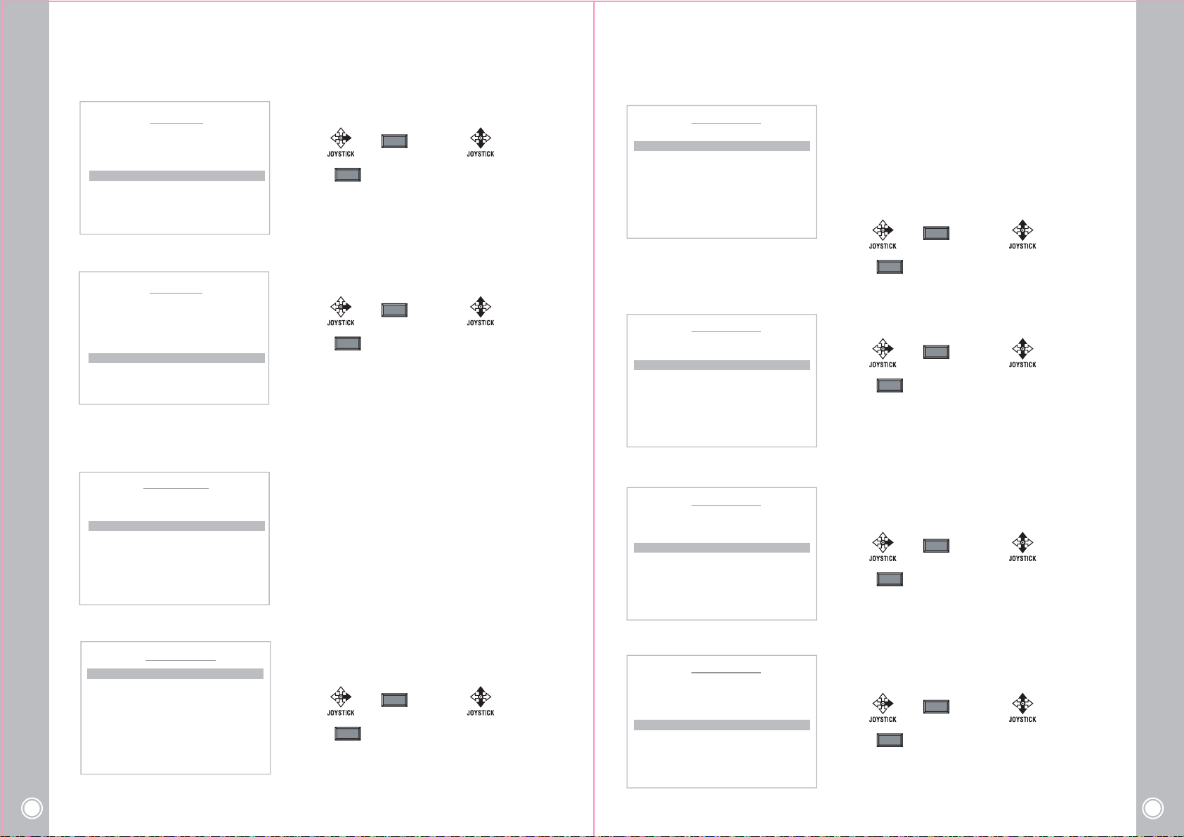
AF MODE: Set the auto focus mode
Select : or Set ON :
Set OFF :
NEAR
NEAR
- SHUTTER SPEED
AUTO EXPO.MENU
AE MODE : MANUAL
SHUTTER SPD : 1/50
SLOWSHUTTER : OFF
IRIS LEVEL : AUTO
GAIN LEVEL : 28dB
AGC MODE : ON
EXPO. MODE : ON
EXPO. LEVEL : 0dB
BACK
< NEAR / RIGHT ઔ SHUTTER SPD >
If you set SHUTTER in the AE MODE, you can control image
brightness by adjusting shutter speed.
NTSC : X512, X128, X64, X32, X16, X8, 1/15, 1/30, 1/60, 1/90, 1/100,
1/180, 1/250, 1/500, 1/1000, 1/1500, 1/2000, 1/5000, 1/10000,
1/20000, 1/50000, 1/100000
PAL : X512, X128, X64, X32, X16, X8, X4, 1/25, 1/50, 1/80, 1/120,
1/150, 1/250, 1/500, 1/1000, 1/1500, 1/2000, 1/5000, 1/10000,
1/20000, 1/50000, 1/100000
Select : or Set ON :
NEAR
- SENSITIVITY
FOCUS MODE : AUTO
FOCUS SPD :
NEAR LIMIT : 10CM
AF MODE : NORMAL
SENSITIVITY : NORMAL
BACK
< NEAR / RIGHT ઔSENSITIVITY >
3) AUTO EXPOSURE
ZOOM MODE
FOCUS MODE
AE MODE
WB MODE
ICR MODE
SPECIAL
CAM RESET
SAVE BACK EXIT
< NEAR / RIGHT ઔ AE SET >
- AE MODE
AE MODE : AUTO
SHUTTER SPD : AUTO
SLOWSHUTTER : OFF
IRIS LEVEL : AUTO
GAIN LEVEL : AUTO
AGC MODE : ON
EXPO. MODE : ON
EXPO. LEVEL : 0dB
BACK
< NEAR / RIGHT ઔ AE MODE >
High Speed Mini PTZ Camera
30
FOCUS MENU
3
CAMERA MENU
ઔ
AUTO EXPO.MENU
SENSITIVITY: Set the sensitivity of focus
Select : or Set ON :
Set OFF :
NEAR
NEAR
AE setting is a function adjusting shutter speed according
to subject’s brightness to get standard amount of exposed
light.
Select AUTO,MANUAL,SHUTTER or IRIS.
Select : or Set ON :
Set OFF :
NEAR
NEAR
- SLOW SHUTTER
AUTO EXPO.MENU
AE MODE : MANUAL
SHUTTER SPD : 1/50
SLOWSHUTTER : OFF
IRIS LEVEL : AUTO
GAIN LEVEL : 28dB
AGC MODE : ON
EXPO. MODE : ON
EXPO. LEVEL : 0dB
BACK
< NEAR / RIGHT ઔ SLOW SHT >
- IRIS LEVEL
AUTO EXPO.MENU
AE MODE : IRIS
SHUTTER SPD : AUTO
SLOWSHUTTER : OFF
IRIS LEVEL : 07
GAIN LEVEL : 28dB
AGC MODE : ON
EXPO. MODE : ON
EXPO. LEVEL : 0dB
BACK
< NEAR / RIGHT ઔ IRIS LEVEL >
- GAIN LEVEL
AUTO EXPO.MENU
AE MODE : IRIS
SHUTTER SPD : AUTO
SLOWSHUTTER : OFF
IRIS LEVEL : 07
GAIN LEVEL : 28dB
AGC MODE : ON
EXPO. MODE : ON
EXPO. LEVEL : 0dB
BACK
< NEAR / RIGHT ઔ GAIN LEVEL >
Set OFF :
NEAR
Select ON/ OFF.
Select : or Set ON :
Set OFF :
NEAR
NEAR
If you set IRIS in the AE MODE, you can set the IRIS level
from 00 to 17 .
Select : or Set ON :
Set OFF :
NEAR
NEAR
If you set MANUAL, IRIS and SHUTTER in the AE MODE, you can
set the GAIN for brighter image from 0~30dB. (Changable by 2dB)
Select : or Set ON :
Set OFF :
NEAR
NEAR
High Speed Mini PTZ Camera
31
Page 17
ઔ
ઔ
ઔ
ઔ
ઔ
ઔ
ઔ
ઔ
ઔ
ઔ
ઔ
ઔ
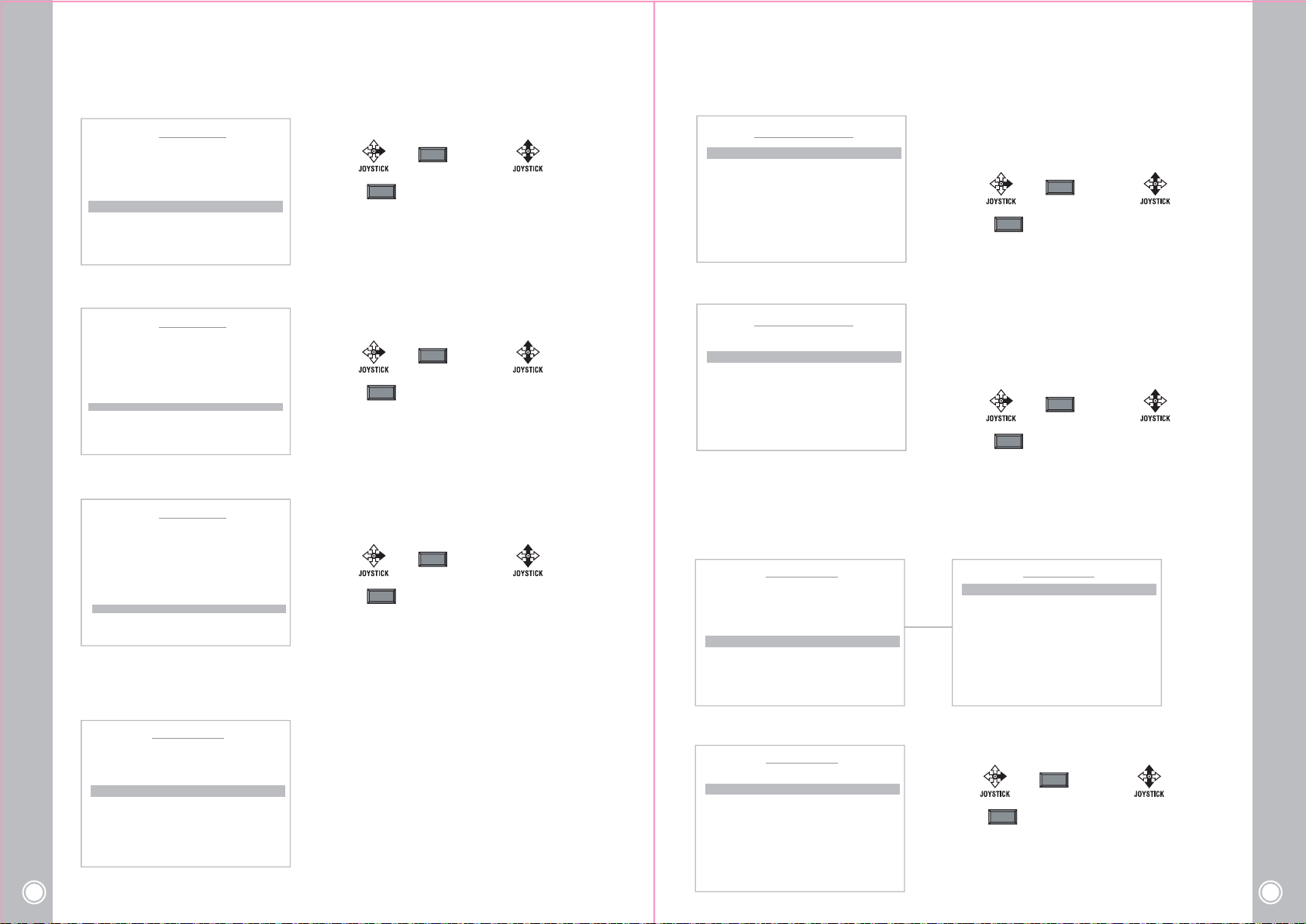
- AGC MODE
AE EXPO.MENU
AE MODE : IRIS
SHUTTER SPD : AUTO
SLOWSHUTTER : OFF
IRIS LEVEL : 07
GAIN LEVEL : 28db
AGC MODE : ON
EXPO. MODE : ON
EXPO. LEVEL : 0dB
BACK
< NEAR / RIGHT ઔ AGC MODE >
Select ON/ OFF in AGC MODE.
Select : or Set ON :
Set OFF :
NEAR
NEAR
- WB MODE
WHITE BALANCE MENU
WB MODE : ATW
RED GAIN : xxx
BLUE GAIN: xxx
BACK
< NEAR / RIGHT ઔWB MODE SEL >
WB MODE: Set the color depend on white balance.
Select AUTO, INDOOR, OUTDOOR, ONEPUSHWB,
ATW or MANUAL.
Select : or Set ON :
Set OFF :
NEAR
NEAR
- EXPO. MODE
AE MODE : AUTO
SHUTTER SPD : AUTO
SLOWSHUTTER : OFF
IRIS LEVEL : AUTO
GAIN LEVEL : AUTO
AGC MODE : ON
EXPO. MODE : ON
EXPO. LEVEL : 0dB
BACK
< NEAR / RIGHT ઔ EXPO. MODE >
- EXPO.LEVEL
AE MODE : AUTO
SHUTTER SPD : AUTO
SLOWSHUTTER : OFF
IRIS LEVEL : AUTO
GAIN LEVEL : AUTO
AGC MODE : ON
EXPO. MODE : ON
EXPO. LEVEL : 0dB
BACK
< NEAR / RIGHT ઔ EXPO. LEVEL >
4) WHITE BALANCE
Set the white balance of camera.
ZOOM MODE
FOCUS MODE
AE MODE
WB MODE
ICR MODE
SPECIAL
CAM RESET
SAVE BACK EXIT
High Speed Mini PTZ Camera
32
< NEAR / RIGHT ઔ WB SET >
AE EXPO.MENU
AE EXPO.MENU
CAMERA MENU
ઔ
Select AUTO or Manual.
Select : or Set ON :
Set OFF :
NEAR
NEAR
If you set ON in the EXPO MODE, you can control this level.
( "0" is standard (±10.5 selectable), changed bt 1.5dB)
Select : or Set ON :
Set OFF :
NEAR
NEAR
White balance setting is a function revising color temperature to
resolve the problem that screen’s colors change by the color
temperature’s difference according to time.
- RED/BLUE GAIN
WHITE BALANCE MENU
WB MODE : MANUAL
RED GAIN : 208
BLUE GAIN: 162
BACK
< NEAR / RIGHT ઔR GAIN SEL >
5) ICR MODE
Set the LED operating depend on ICR Mode.
Select DAY ,NIGHT and
DAY: IR OFF NIGHT: IR ON
CAMERA MENU
ZOOM MODE
FOCUS MODE
AE MODE
WB MODE
ICR MODE
SPECIAL
CAMERA RESET
SAVE BACK EXIT
< NEAR / RIGHT ઔICR SET >
- ICR THRESHOLD
ICR MODE : AUTO
ICR THRESHOLD :11
BACK
< NEAR / RIGHT ઔDAY LEVEL >
AUTO mode and the LED will be operated depend on this mode.
ઔ
ICR MENU
RED GAIN: Adjust red color level from 0~255.
(Standard level is 025)
BLUE GAIN: Adjust blue color level from 0~255.
(Standard level is 025)
Select : or Set ON :
Set OFF :
Set the ICR THRESHOLD from 00 to 28 .
NEAR
ICR MODE : AUTO
ICR THRESHOLD :11
BACK
< NEAR / RIGHT ઔICR MODE >
Select : or Set ON :
Set OFF :
NEAR
NEAR
ICR MENU
NEAR
High Speed Mini PTZ Camera
33
Page 18
ઔ
ઔ
ઔ
ઔ
ઔ
ઔ
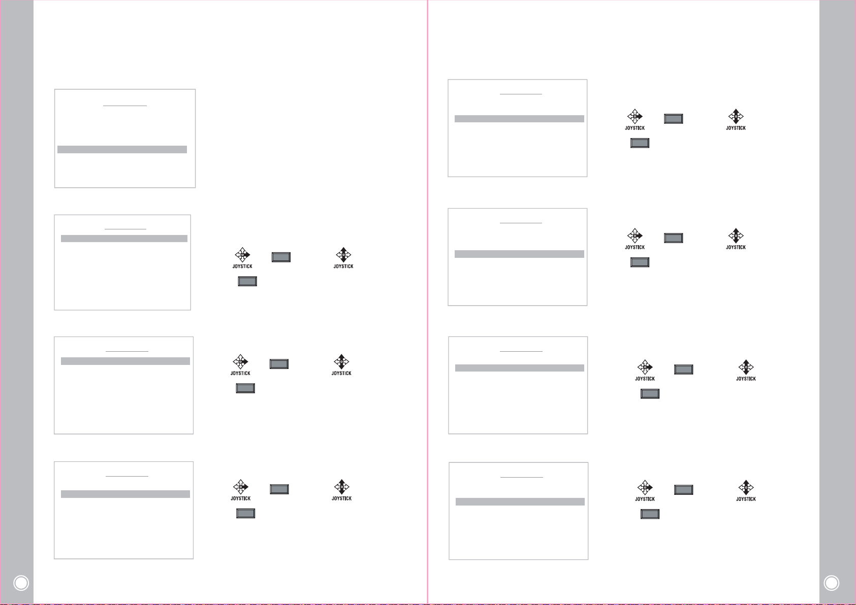
6) SPECIAL
ઔ
ઔ
In the Special menu, it’s available to set APERTUREGAIN, FLICKERLESS, BACK LIGHT
DNR LEVEL and WDR.
MOTION
DOME
CAMERA
CLEAR
SPECIAL
CAM RESET
SAVE BACK EXIT
< NEAR / RIGHT
MAIN MENU
ઔ
SPECIAL SET >
- HLC CLIP LEVEL
SPECIAL MENU
STABILIZER : OFF
HLC MODE : OFF
HLC CLIPLEV : XX
HLC LEVEL : XX
BACK
< NEAR / RIGHT ઔLEVEL>
HLC CLIP LEVEL : Select HLC function ON and set the HLC
CLIP LEVEL.(0~06)
Select : or Set ON :
Set OFF :
NEAR
NEAR
- SUB SP MODE
SPECIAL MENU
SUB SP MODE
APERTUREGAIN : 07
FLICKERLESS : OFF
BACK LIGHT : OFF
DNR LEVEL : AUTO
WDR MODE : OFF
BACK
< NEAR / RIGHT ઔSUB MENU >
ઔ
- STABILIZER
SPECIAL MENU
STABILIZER : OFF
HLC MODE : OFF
HLC CLIPLEV : XX
HLC LEVEL : XX
BACK
< NEAR / RIGHT ઔON/OFF>
- HLC MODE
SPECIAL MENU
STABILIZER : OFF
HLC MODE : OFF
HLC CLIPLEV : XX
HLC LEVEL : XX
SUB SP MODE : In the Special menu, it’s available
to set special function of the camera
Select : or Set ON :
Set OFF :
NEAR
NEAR
STABILIZER: Select ON or OFF.
Select : or Set ON :
Set OFF :
NEAR
NEAR
HLC MODE : Select ON or OFF.
Select : or Set ON :
Set OFF :
NEAR
NEAR
- HLC LEVEL
SPECIAL MENU
STABILIZER : OFF
HLC MODE : OFF
HLC CLIPLEV : XX
HLC LEVEL : XX
BACK
< NEAR / RIGHT ઔLEVEL>
- APERTUREGAIN
SPECIAL MENU
SUB SP MODE
APERTUREGAIN : 07
FLICKERLESS : OFF
BACK LIGHT : OFF
DNR LEVEL : AUTO
WDR MODE : LEV 7
BACK
< NEAR / RIGHT ઔAPERTURE >
- FLICKERLESS
SPECIAL MENU
SUB SP MODE
APERTUREGAIN : 07
FLICKERLESS : OFF
BACK LIGHT : OFF
DNR LEVEL : AUTO
WDR MODE : LEV 7
HLC LEVEL : Set the HLC LEVEL.(0~02)
Select : or Set ON :
Set OFF :
NEAR
NEAR
Set the APERTUREGAIN value.(0~15)
Select : or Set ON :
Set OFF :
NEAR
NEAR
Select ON/OFF in the FLICKERLESS function.
Select : or Set ON :
Set OFF :
NEAR
NEAR
BACK
< NEAR / RIGHT ઔ MODE>
High Speed Mini PTZ Camera
34
BACK
< NEAR / RIGHT ઔFLICKERLESS >
High Speed Mini PTZ Camera
35
Page 19
5. SPECIFICATION
ઔ
ઔ
ઔ
ઔ
ઔ
ઔ
ઔ
ઔ
ઔ
- BACK LIGHT
SUB SP MODE
APERTUREGAIN : 07
FLICKERLESS : OFF
BACK LIGHT : OFF
DNR LEVEL : AUTO
WDR MODE : LEV 7
BACK
< NEAR / RIGHT ઔBACK LIGHT >
- DNR LEVEL
SUB SP MODE
APERTUREGAIN : 07
FLICKERLESS : OFF
BACK LIGHT : OFF
DNR LEVEL : AUTO
WDR MODE : LEV 7
BACK
< NEAR / RIGHT ઔ DNR LEVEL >
- WDR MODE
SUB SP MODE
APERTUREGAIN : 07
FLICKERLESS : OFF
BACK LIGHT : OFF
DNR LEVEL : AUTO
WDR MODE : LEV 7
BACK
< NEAR / RIGHT ઔ WDR MODE >
7) CAMERA RESET
Make initialize the setting value which is set in CAMERA MENU.
ZOOM MODE
FOCUS MODE
AE MODE
WB MODE
ICR MODE
SPECIAL
CAM RESET
SAVE BACK EXIT
High Speed Mini PTZ Camera
36
< NEAR / RIGHT ઔ RESET >
SPECIAL MENU
SPECIAL MENU
SPECIAL MENU
CAMERA MENU
ઔ
<YES> NO
Select ON/OFF in the BACK LIGHT function.
Select : or Set ON :
Set OFF :
NEAR
NEAR
Set the DNR LEVEL from AUTO, OFF and 1 ~ 10.
Select : or Set ON :
Set OFF :
NEAR
NEAR
Set the WDR MODE from OFF, LEV1 ~LEV7.
Select : or Set ON :
Set OFF :
NEAR
Move : Select :
NEAR
NEAR
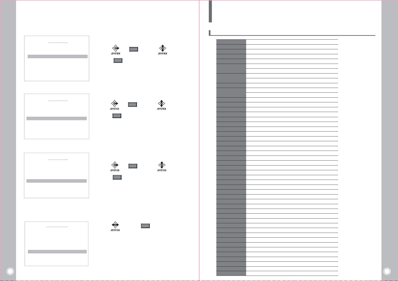
5. 1 Camera Specification
Image Sensor
Total Pixels
Scanning system
Scanning Frequency
Sync. System
Resolution
Min. illumination
Video Output
S/N Ratio
Lens type
Zoom Ratio
Focal Length
Aperture Ratio
Focus
Focus Distance
E. Zoom
Exposure
Gain Control
Shutter Speed
Digital Shutter Speed
Flickerless
Brightness
WDR / BLC
Day&Night
White Balance
Image DNR
HR
Mirror
Sharpness
Effect
Freeze
Intelligent
Privacy Mask
Motion Detection
Object Detection
Special
Sync Mode
Phase
Display
Disp Sel(Off / On)
Init Sel(Off / On)
Protocols
Communication
Power Consumption
Operating Temperature
Operating Humidity
Certification
1/4" SONY Super HAD II(Double Scan) CCD
NTSC : 1028(H) × 508(V) PAL : 1028(H) x 596(V)
NTSC : 15.734KHz(H), 59.94Hz(V) PAL : 15.625KHz(H), 50Hz(V)
Color DSS : 0.001 lux , BW DSS : 0.0004 lux
NTSC : 1/60 ~ 1/100,000 sec PAL : 1/50 ~ 1/100,000 sec
ATW / One-Push / Indoor / Outdoor / Manual / Auto
Disp Sel / Init Sel / Set Title / Set Init Msg / Language
ID / Baud Rate / Protocol / Version / Init Msg
AC 24V 3A(OUTDOOR), AC 24V 1A(INDOOR), DC 12V 1.5A(INDOOR)
Interlace
Internal
700 TV lines (COLOR)
800 TV lines (BW)
Color : 0.5 lux , BW : 0.2 lux
1.0 Vp-p (75 ohm, composite)
More than 50dB (AGC off)
12x Day & Night Zoom Lens
Optical x12, Digital x32 Zoom
f = 3.8 mm ~ 45.6 mm
F1.6 (wide) ~ F2.7 (tele)
Auto / Zoom-Trig / Manual
0.1 / 1.0 / 1.3 / 2.0 / 6.0 m
Off / Max 2x~32x
Auto / Shutter PRI / Manual
Off / On (Auo Max 30dB)
Off / Max 2x~512x
Off / On
1 ~15 steps
Off / WDR / BLC
Auto / Sens-in / Ext / Day / Night
Off / Manual / Auto
Off / 1~7 steps
Off / H / V / H+V
1 ~ 16 steps
Off / Negative / B&W
Off / On
Privacy / MD / OD
Off / 16 positions
Off / 3 positions
Off / On
Sync / Phase / Comm
INT / LL
0 ~ 255 steps
ID / Title / Zoom Ratio
PELCO-D, PELCO-P, WTX
RS-485
0ºC ~ +50ºC (Indoor )
20% ~ 75% RH
CE, FCC
High Speed Mini PTZ Camera
37
Page 20
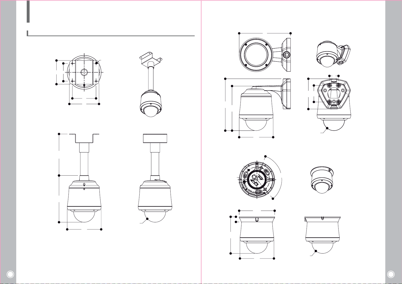
6. DIMENSION
6. 1 Dimension
120
OPTION
260
Ø8
90
83.5
120
150
262.7
225.8
Ø172
Ø128
120°
Ø4.5
153.5
Ø107.5
46
High Speed Mini PTZ Camera
38
236.7
Ø172
Ø107.5
185.7
Ø180.3
26
Ø172
R53.8
High Speed Mini PTZ Camera
39
Page 21
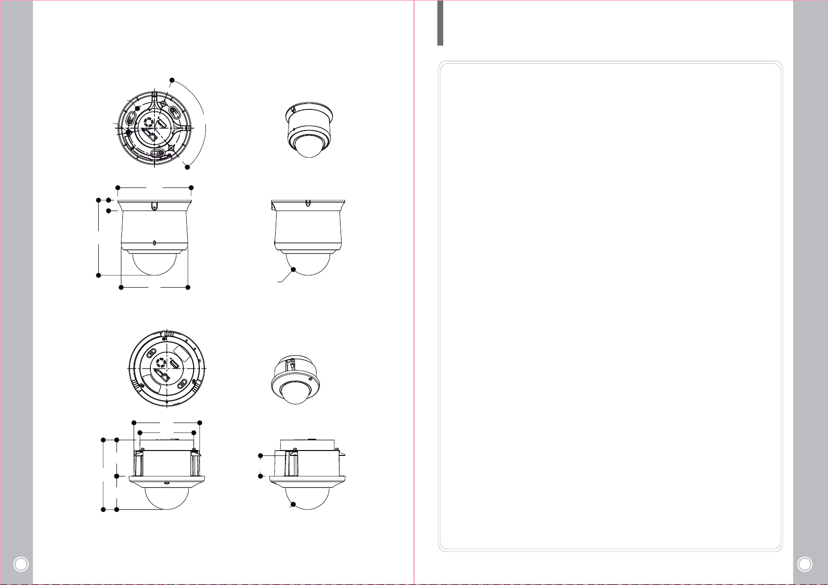
Ø4.5
184.9
MEMO
Ø128
120°
Ø180.3
26
High Speed Mini PTZ Camera
40
171.2
89.1
82.1
Ø164
R53.8
161.6
132.4
0~50
R53.8
High Speed Mini PTZ Camera
41
Page 22

High Speed Mini PTZ Camera
42
High Speed Mini PTZ Camera
43
 Loading...